Asrock A320M/ac Bruksanvisning
Läs nedan 📖 manual på svenska för Asrock A320M/ac (75 sidor) i kategorin moderkort. Denna guide var användbar för 5 personer och betygsatt med 4.5 stjärnor i genomsnitt av 2 användare
Sida 1/75


Version 1.0
Published January 2020
Copyright©2020 ASRock INC. All rights reserved.
Copyright Notice:
No part of this documentation may be reproduced, transcribed, transmitted, or
translated in any language, in any form or by any means, except duplication of
documentation by the purchaser for backup purpose, without written consent of
ASRock Inc.
Products and corporate names appearing in this documentation may or may not
be registered trademarks or copyrights of their respective companies, and are used
only for identication or explanation and to the owners’ benet, without intent to
infringe.
Disclaimer:
Specications and information contained in this documentation are furnished for
informational use only and subject to change without notice, and should not be
constructed as a commitment by ASRock. ASRock assumes no responsibility for
any errors or omissions that may appear in this documentation.
With respect to the contents of this documentation, ASRock does not provide
warranty of any kind, either expressed or implied, including but not limited to
the implied warranties or conditions of merchantability or tness for a particular
purpose.
In no event shall ASRock, its directors, ocers, employees, or agents be liable for
any indirect, special, incidental, or consequential damages (including damages for
loss of prots, loss of business, loss of data, interruption of business and the like),
even if ASRock has been advised of the possibility of such damages arising from any
defect or error in the documentation or product.
is device complies with Part 15 of the FCC Rules. Operation is subject to the following
two conditions:
(1) this device may not cause harmful interference, and
(2) this device must accept any interference received, including interference that
may cause undesired operation.
CALIFORNIA, USA ONLY
e Lithium battery adopted on this motherboard contains Perchlorate, a toxic substance
controlled in Perchlorate Best Management Practices (BMP) regulations passed by the
California Legislature. When you discard the Lithium battery in California, USA, please
follow the related regulations in advance.
“Perchlorate Material-special handling may apply, see www.dtsc.ca.gov/hazardouswaste/
perchlorate”
ASRock Website: http://www.asrock.com

AUSTRALIA ONLY
Our goods come with guarantees that cannot be excluded under the Australian Consumer
Law. You are entitled to a replacement or refund for a major failure and compensation for
any other reasonably foreseeable loss or damage caused by our goods. You are also entitled
to have the goods repaired or replaced if the goods fail to be of acceptable quality and the
failure does not amount to a major failure. If you require assistance please call ASRock Tel
: +886-2-28965588 ext.123 (Standard International call charges apply)
e terms HDMI® and HDMI High-Denition Multimedia Interface, and the
HDMI logo are trademarks or registered trademarks of HDMI Licensing LLC in the
United States and other countries.
CE Warning
is device complies with directive 2014/53/EU issued by the Commision of the European
Community.
is equipment complies with EU radiation exposure limits set forth for an uncontrolled
environment.
is equipment should be installed and operated with minimum distance 20cm between
the radiator & your body.
Operations in the 5.15-5.35GHz band are restricted to indoor usage only.
Radio transmit power per transceiver type
Function Frequency Maximum Output Power (EIRP)
WiFi
2400-2483.5 MHz 18.5 + / -1.5 dbm
5150-5250 MHz 21.5 + / -1.5 dbm
5250-5350 MHz 18.5 + / -1.5 dbm (no TPC)
21.5 + / -1.5 dbm (TPC)
5470-5725 MHz 25.5 + / -1.5 dbm (no TPC)
28.5 + / -1.5 dbm (TPC)
Bluetooth 2400-2483.5 MHz 8.5 + / -1.5 dbm

Contents
Chapter 1 Introduction 1
1.1 Package Contents 1
1.2 Specications 2
1.3 Motherboard Layout 7
1.4 I/O Panel 9
1.5 WiFi-802.11ac Module and ASRock WiFi 2.4/5 GHz
Antenna 10
Chapter 2 Installation 11
2.1 Installing the CPU 12
2.2 Installing the CPU Fan and Heatsink 14
2.3 Installing Memory Modules (DIMM) 22
2.4 Expansion Slots (PCI Express Slots) 26
2.5 Jumpers Setup 27
2.6 Onboard Headers and Connectors 28
2.7 M.2_SSD (NGFF) Module Installation Guide 32
Chapter 3 Software and Utilities Operation 36
3.1 Installing Drivers 36
3.2 ASRock Motherboard Utility (A-Tuning) 37
3.2.1 Installing ASRock Motherboard Utility (A-Tuning) 37
3.2.2 Using ASRock Motherboard Utility (A-Tuning) 37
3.3 ASRock Live Update & APP Shop 40
3.3.1 UI Overview 40
3.3.2 Apps 41

3.3.3 BIOS & Drivers 44
3.3.4 Setting 45
Chapter 4 UEFI SETUP UTILITY 46
4.1 Introduction 46
4.1.1 UEFI Menu Bar 46
4.1.2 Navigation Keys 47
4.2 Main Screen 48
4.3 OC Tweaker Screen 49
4.4 Advanced Screen 51
4.4.1 CPU Conguration 52
4.4.2 Onboard Devices Conguration 53
4.4.3 Storage Conguration 54
4.4.4 Super IO Conguration 55
4.4.5 ACPI Conguration 56
4.4.6 Trusted Computing 57
4.4.7 AMD CBS 58
4.4.8 AMD PBS 59
4.5 Tools 60
4.6 Hardware Health Event Monitoring Screen 61
4.7 Security Screen 63
4.8 Boot Screen 64
4.9 Exit Screen 66

A320M/ac
1
English
Chapter 1 Introduction
ank you for purchasing ASRock A320M/ac motherboard, a reliable motherboard
produced under ASRock’s consistently stringent quality control. It delivers excellent
performance with robust design conforming to ASRock’s commitment to quality
and endurance.
In this manual, Chapter 1 and 2 contains the introduction of the motherboard
and step-by-step installation guides. Chapter 3 contains the operation guide of the
soware and utilities. Chapter 4 contains the conguration guide of the BIOS setup.
1.1 Package Contents
• ASRock A320M/ac Motherboard (Micro ATX Form Factor)
• ASRock A320M/ac Quick Installation Guide
• ASRock A320M/ac Support CD
• 1 x I/O Panel Shield
• 2 x Serial ATA (SATA) Data Cables (Optional)
• 2 x ASRock WiFi 2.4/5 GHz Antennas (Optional)
• 1 x Screw for M.2 Socket (Optional)
Because the motherboard specications and the BIOS soware might be updated, the
content of this manual will be subject to change without notice. In case any modica-
tions of this manual occur, the updated version will be available on ASRock’s website
without further notice. If you require technical support related to this motherboard,
please visit our website for specic information about the model you are using. You
may nd the latest VGA cards and CPU support list on ASRock’s website as well.
ASRock website http://www.asrock.com.

English
2
1.2 Specications
Platform • Micro ATX Form Factor
• Solid Capacitor design
CPU • Supports AMD Socket AM4 A-Series APUs (Bristol Ridge)
and Ryzen Series CPUs (Matisse, Picasso, Summit Ridge,
Raven Ridge and Pinnacle Ridge)
• 6 Power Phase design
• Supports CPU up to 105W
Chipset • AMD Promontory A320
Memory • Dual Channel DDR4 Memory Technology
• 2 x DDR4 DIMM Slots
• AMD Ryzen series CPUs (Matisse) support DDR4
3200/2933/2667/2400/2133 ECC & non-ECC, un-buered
memory*
• AMD Ryzen series CPUs (Pinnacle Ridge) support DDR4
3200+(OC)/2933(OC)/2667/2400/2133 ECC & non-ECC, un-
buered memory*
• AMD Ryzen series CPUs (Picasso) support DDR4
2933/2667/2400/2133 non-ECC, un-buered memory*
• AMD Ryzen series CPUs (Summit Ridge) support DDR4
3200+(OC)/2933(OC)/2667/2400/2133 ECC & non-ECC, un-
buered memory*
• AMD Ryzen series CPUs (Raven Ridge) support DDR4
3200+(OC)/2933/2667/2400/2133 non-ECC, un-buered
memory*
• AMD 7th Gen A-Series APUs support DDR4 2400/2133 non-
ECC, un-buered memory*
* For Ryzen Series CPUs (Picasso and Raven Ridge), ECC is only
supported with PRO CPUs.
* Please refer to Memory Support List on ASRock’s website for
more information. (http://www.asrock.com/)
* Please refer to page 22 for DDR4 UDIMM maximum
frequency support.
• Max. capacity of system memory: 32GB
• 15μ Gold Contact in DIMM Slots

A320M/ac
3
English
Expansion
Slot
AMD Ryzen series CPUs (Matisse, Summit Ridge and
Pinnacle Ridge)
• 1 x PCI Express 3.0 x16 Slot (PCIE2: x16 mode)*
AMD 7th A-Series APUs
• 1 x PCI Express 3.0 x16 Slot (PCIE2: p9-x8 mode)*
AMD Ryzen series CPUs (Picasso, Raven Ridge)
• 1 x PCI Express 3.0 x16 Slot (PCIE2: p9-x8 mode)*
AMD Athlon series CPUs
• 1 x PCI Express 3.0 x16 Slot (PCIE2: p9-x4 mode)*
* Supports NVMe SSD as boot disks
• 1 x PCI Express 2.0 p9-x1 Slot
Graphics • Integrated AMD RadeonTM Vega Series Graphics in Ryzen
Series APU*
• Integrated AMD RadeonTM R-Series Graphics in A-series
APU*
* Actual support may vary by CPU
• DirectX 12, Pixel Shader 5.0
• Shared memory default 2GB. Max Shared memory supports
up to 16GB.
* e Max shared memory 16GB requires 32GB system memory
installed.
• Supports HDMI 1.4 with max. resolution up to 4K x 2K
(4096x2160) @ 24Hz / (3840x2160) @ 30Hz
• Supports Auto Lip Sync, Deep Color (12bpc), xvYCC and
HBR (High Bit Rate Audio) with HDMI 1.4 Port (Compliant
HDMI monitor is required)
• Supports HDCP 1.4 with HDMI 1.4 Port
• Supports Full HD 1080p Blu-ray (BD) playback with HDMI
1.4 Port
Audio • 7.1 CH HD Audio (Realtek ALC887 Audio Codec)
• Supports Surge Protection
• ELNA Audio Caps

English
4
LAN • PCIE p10-x1 Gigabit LAN 10/100/1000 Mb/s
• Realtek RTL8111H
• Supports Wake-On-LAN
• Supports Lightning/ESD Protection
• Supports Energy Ecient Ethernet 802.3az
• Supports PXE
Wireless
LAN
• Intel® 802.11ac WiFi Module
• Supports IEEE 802.11a/b/g/n/ac
• Supports Dual-Band (2.4/5 GHz)
• Supports high speed wireless connections up to 433Mbps
• Supports Bluetooth 4.2 / 3.0 + High speed class II
Rear Panel
I/O
• 2 x Antenna Ports
• 1 x PS/2 Mouse/Keyboard Port
• 1 x HDMI Port
• 2 x USB 2.0 Ports (Supports ESD Protection)
• 4 x USB 3.2 Gen1 Ports (Supports ESD Protection)
• 1 x RJ-45 LAN Port with LED (ACT/LINK LED and SPEED
LED)
• HD Audio Jacks: Line in / Front Speaker / Microphone
Storage • 4 x SATA3 6.0 Gb/s Connectors, support RAID (RAID 0,
RAID 1 and RAID 10), NCQ, AHCI and Hot Plug
• 1 x Ultra M.2 Socket, supports M Key type 2242/2260/2280
M.2 SATA3 6.0 Gb/s module and M.2 PCI Express module up
to Gen3 p10-x4 (32 Gb/s) (with Matisse, Picasso, Summit Ridge,
Raven Ridge and Pinnacle Ridge) or Gen3 x2 (16 Gb/s) (with
A-Series APU and Athlon 2xxGE series APU)*
* Supports NVMe SSD as boot disks
* Supports ASRock U.2 Kit

English
6
* For detailed product information, please visit our website: http://www.asrock.com
Please realize that there is a certain risk involved with overclocking, including adjust-
ing the setting in the BIOS, applying Untied Overclocking Technology, or using third-
party overclocking tools. Overclocking may aect your system’s stability, or even cause
damage to the components and devices of your system. It should be done at your own
risk and expense. We are not responsible for possible damage caused by overclocking.

A320M/ac
7
English
1.3 Motherboard Layout
BIOS
ROM
DDR4_A1 (64 bit, 288-pin module)
DDR4_A2 (64 bit, 288-pin module)
Super
I/O
LAN
AUDIO
CODEC
PCIE2
PCIE1
US B_3 _ 4
US B_5 _ 6
HD _A UDI O 1
1
CPU_FAN1
CHA_ FAN2
1
CO M1
3
4
2
9
5
US 2.B 0
T: USB 1
B: USB2
CMOS
Battery
1
US B3_ 5_6
1
HDL ED R ESET
PL ED PW RBT N
PAN EL1
1
RoHS
17
15
13 1214
18
SPK_ CI1
1
Top:
LINE IN
Ce nt e r:
FR ON T
Bo tt om :
MIC IN
RJ-45 LAN
ATX 12V
7
8
6
C LR C MO S1
1
SATA3 _3
SATA3 _4
AMD
Promont ory
A320
SOCKET AM4
CHA_FAN1
11
10
SATA3 _1
SATA3 _2
16
M2 _1
A320M/ac
HDM I1
Ultr M.a 2
PCIe G e n3 x4
ATX PW R1
M 22_WIFI_
US 3 . Gen1B 2
T: USB1
B: USB 2
US 3 . Gen1B 2
T: USB3
B: USB 4
PS 2
Ke yb oa rd
/Mou se

English
8
No. Description
1 ATX 12V Power Connector (ATX12V1)
2 CPU Fan Connector (CPU_FAN1)
3 2 x 288-pin DDR4 DIMM Slots (DDR4_A1, DDR4_A2)
4 ATX Power Connector (ATXPWR1)
5 USB 3.2 Gen1 Header (USB3_5_6)
6 USB 2.0 Header (USB_3_4)
7 USB 2.0 Header (USB_5_6)
8 SATA3 Connector (SATA3_3)
9 SATA3 Connector (SATA3_4)
10 SATA3 Connector (SATA3_1)
11 SATA3 Connector (SATA3_2)
12 System Panel Header (PANEL1)
13 Chassis Intrusion and Speaker Header (SPK_CI1)
14 COM Port Header (COM1)
15 Chassis Fan Connector (CHA_FAN2)
16 Clear CMOS Header (CLRCMOS1)
17 Front Panel Audio Header (HD_AUDIO1)
18 Chassis Fan Connector (CHA_FAN1)

English
10
1.5 WiFi-802.11ac Module and ASRock WiFi 2.4/5 GHz
Antenna
WiFi-802.11ac + BT Module
is motherboard comes with an exclusive WiFi 802.11 a/b/g/n/ac + BT v4.2
module (pre-installed on the rear I/O panel) that oers support for WiFi 802.11 a/b/
g/n/ac connectivity standards and Bluetooth v4.2. WiFi + BT module is an easy-to-
use wireless local area network (WLAN) adapter to support WiFi + BT. Bluetooth
v4.2 standard features Smart Ready technology that adds a whole new class of
functionality into the mobile devices. BT 4.2 also includes Low Energy Technology
and ensures extraordinary low power consumption for PCs.
* e transmission speed may vary according to the environment.

A320M/ac
11
English
is is a Micro ATX form factor motherboard. Before you install the motherboard,
study the conguration of your chassis to ensure that the motherboard ts into it.
Pre-installation Precautions
Take note of the following precautions before you install motherboard components
or change any motherboard settings.
• Make sure to unplug the power cord before installing or removing the motherboard.
Failure to do so may cause physical injuries to you and damages to motherboard
components.
• In order to avoid damage from static electricity to the motherboard’s components,
NEVER place your motherboard directly on a carpet. Also remember to use a grounded
wrist strap or touch a safety grounded object before you handle the components.
• Hold components by the edges and do not touch the ICs.
• Whenever you uninstall any components, place them on a grounded anti-static pad or
in the bag that comes with the components.
• When placing screws to secure the motherboard to the chassis, please do not over-
tighten the screws! Doing so may damage the motherboard.
Chapter 2 Installation
English
12
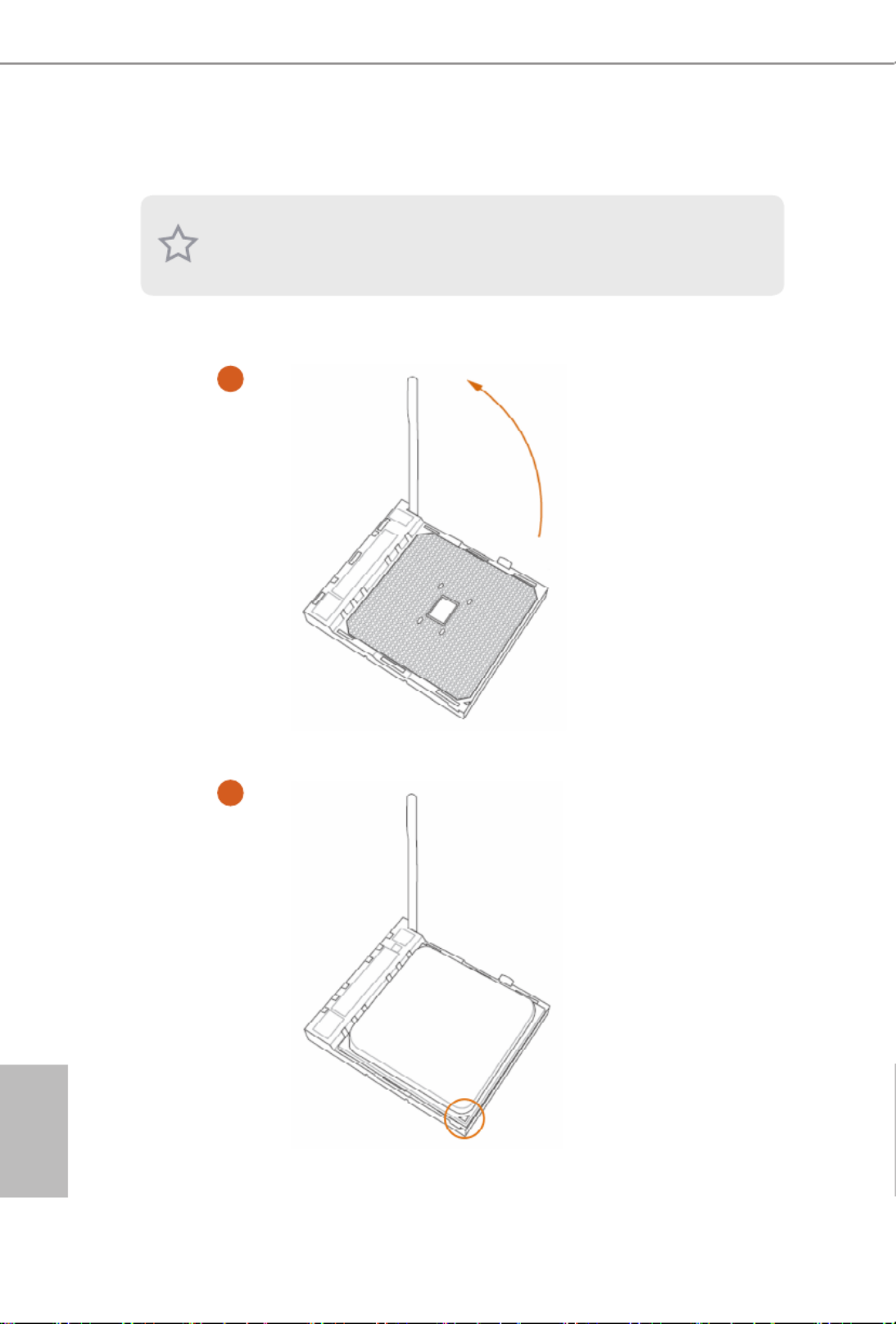
2.1 Installing the CPU
Unplug all power cables before installing the CPU.
2
1

A320M/ac
13
English
3
English
14
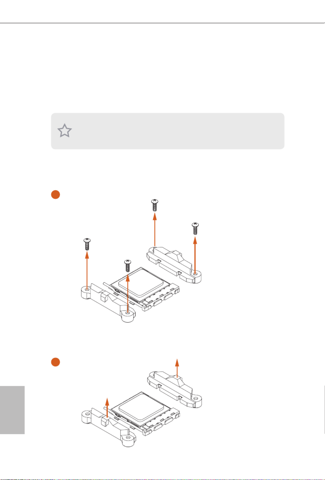
2.2 Installing the CPU Fan and Heatsink
Aer you install the CPU into this motherboard, it is necessary to install a larger
heatsink and cooling fan to dissipate heat. You also need to spray thermal grease
between the CPU and the heatsink to improve heat dissipation. Make sure that the
CPU and the heatsink are securely fastened and in good contact with each other.
Installing the CPU Box Cooler SR1
Please turn o the power or remove the power cord before changing a CPU or heatsink.
1
2

A320M/ac
15
English
3
4
C
PU
_
FAN1
4-pin FAN cable

English
16
Installing the AM4 Box Cooler SR2
1
2

A320M/ac
17
English
3

English
18
4-pin FAN cable
4
C
PU
_
FA N1

A320M/ac
19
English
Installing the AM4 Box Cooler SR3
1
2

English
20
3
4

A320M/ac
21
English
5
CPU_FAN1
Please note that this connector is the interface to the LED control board on the SR3, it requires the AMD
utility "SR3 Settings Soware" to control the LED.
*e diagram shown here are for reference only. Please refer to page 28 for the orientation of USB Header.
C
PU
_
FA
N1
6
U
S
B
4-pin FAN cable
USB 2.0 Header

English
22
2.3 Installing Memory Modules (DIMM)
is motherboard provides two 288-pin DDR4 (Double Data Rate 4) DIMM slots,
and supports Dual Channel Memory Technology.
DDR4 UDIMM Maximum Frequency Support
A-Series APUs:
Ryzen Series CPUs (Matisse):
1. For dual channel conguration, you always need to install identical (the same
brand, speed, size and chip-type) DDR4 DIMM pairs.
2. It is unable to activate Dual Channel Memory Technology with only one memory
module installed.
3. It is not allowed to install a DDR, DDR2 or DDR3 memory module into a DDR4
slot; otherwise, this motherboard and DIMM may be damaged.
UDIMM Memory Slot Frequency
(Mhz)
A1 B1
SR - 2400
- SR 2400
DR - 2400
- DR 2400
SR SR 2400
DR DR 2400
UDIMM Memory Slot Frequency
(Mhz)
A1 B1
SR - 3200
- SR 3200
DR - 3200
- DR 3200
SR SR 3200
DR DR 3200

A320M/ac
23
English
Ryzen Series CPUs (Pinnacle Ridge):
Ryzen Series CPUs (Picasso):
UDIMM Memory Slot Frequency
(Mhz)
A1 B1
SR - 2933
- SR 2933
DR - 2933
- DR 2933
SR SR 2933
DR DR 2933
UDIMM Memory Slot Frequency
(Mhz)
A1 B1
SR - 2933
- SR 2933
DR - 2667
- DR 2667
SR SR 2933
DR DR 2667

English
24
Ryzen Series CPUs (Summit Ridge):
Ryzen Series CPUs (Raven Ridge):
SR: Single rank DIMM, 1Rx4 or 1Rx8 on DIMM module label
DR: Dual rank DIMM, 2Rx4 or 2Rx8 on DIMM module label
UDIMM Memory Slot Frequency
(Mhz)
A1 B1
SR - 2667
- SR 2667
DR - 2667
- DR 2667
SR SR 2667
DR DR 2667
UDIMM Memory Slot Frequency
(Mhz)
A1 B1
SR - 2933
- SR 2933
DR - 2667
- DR 2667
SR SR 2933
DR DR 2667

A320M/ac
25
English
e DIMM only ts in one correct orientation. It will cause permanent damage to
the motherboard and the DIMM if you force the DIMM into the slot at incorrect
orientation.
1
2
3
English
26
2.4 Expansion Slots (PCI Express Slots)
ere are 2 PCI Express slots on the motherboard.
PCIe slots:
PCIE1 (PCIe 2.0 p32-x1 slot) is used for PCI Express p32-x1 lane width cards
PCIE2 (PCIe 3.0 x16 slot) is used for PCI Express x16 lane width graphics cards.
PCIe Slot Congurations
Before installing an expansion card, please make sure that the power supply is
switched o or the power cord is unplugged. Please read the documentation of the
expansion card and make necessary hardware settings for the card before you start
the installation.
CPU PCIE2
Ryzen series CPUs (Matisse) x16
Ryzen series CPUs (Pinnacle Ridge) x16
Ryzen series CPUs (Summit Ridge) x16
Ryzen series CPUs (Picasso) x8
Ryzen series CPUs (Raven Ridge) x8
Athlon 2xxGE series APU x4
7th A-Series APUs x8
For a better thermal environment, please connect a chassis fan to the motherboard’s
chassis fan connector (CHA_FAN1 or CHA_FAN2 ) when using multiple graphics cards.

A320M/ac
27
English
If you clear the CMOS, the case open may be detected. Please adjust the BIOS option
“Clear Status” to clear the record of previous chassis intrusion status.
2.5 Jumpers Setup
e illustration shows how jumpers are setup. When the jumper cap is placed on
the pins, the jumper is “Short”. If no jumper cap is placed on the pins, the jumper is
“Open”.
Clear CMOS Header
(CLRCMOS1)
(see p.7, No. 16)
Short: Clear CMOS
Open: Default
CLRCMOS1 allows you to clear the data in CMOS. e data in CMOS includes
system setup information such as system password, date, time, and system setup
parameters. To clear and reset the system parameters to default setup, please
turn o the computer and unplug the power cord, then use a jumper cap to short
the pins on CLRCMOS1 for 3 seconds. Please remember to remove the jumper
cap aer clearing the CMOS. If you need to clear the CMOS when you just nish
updating the BIOS, you must boot up the system rst, and then shut it down
before you do the clear-CMOS action.
2-pin Jumper
English
28
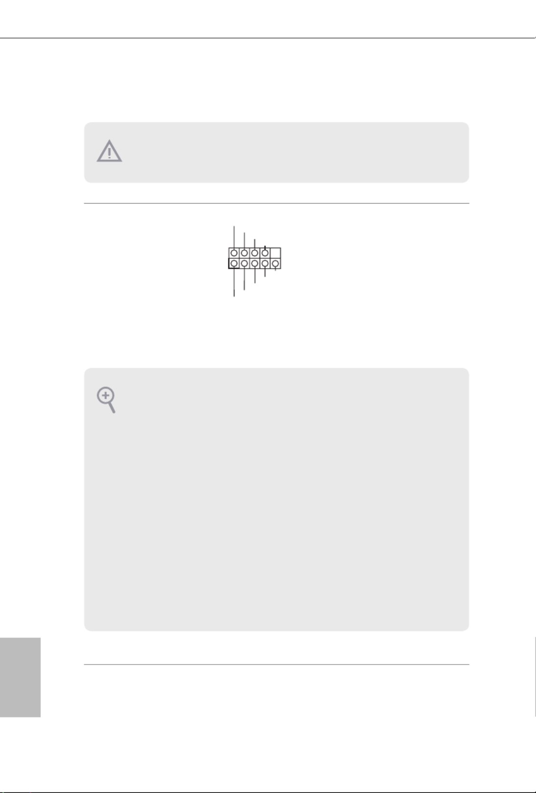
2.6 Onboard Headers and Connectors
System Panel Header
(9-pin PANEL1)
(see p.7, No. 12)
Connect the power
button, reset button and
system status indicator on
the chassis to this header
according to the pin
assignments below. Note
the positive and negative
pins before connecting
the cables.
Onboard headers and connectors are NOT jumpers. Do NOT place jumper caps over
these headers and connectors. Placing jumper caps over the headers and connectors
will cause permanent damage to the motherboard.
GND
R #ESET
PWRBTN#
PLED-
PLED+
GND
HDLED-
HDLED+
1
GND
PWRBTN (Power Button):
Connect to the power button on the chassis front panel. You may congure the way to turn
o your system using the power button.
RESET (Reset Button):
Connect to the reset button on the chassis front panel. Press the reset button to restart the
computer if the computer freezes and fails to perform a normal restart.
PLED (System Power LED):
Connect to the power status indicator on the chassis front panel. e LED is on when the
system is operating. e LED keeps blinking when the system is in S1/S3 sleep state. e
LED is o when the system is in S4 sleep state or powered o (S5).
HDLED (Hard Drive Activity LED):
Connect to the hard drive activity LED on the chassis front panel. e LED is on when the
hard drive is reading or writing data.
e front panel design may dier by chassis. A front panel module mainly consists of power
button, reset button, power LED, hard drive activity LED, speaker and etc. When connect-
ing your chassis front panel module to this header, make sure the wire assignments and the
pin assignments are matched correctly.

A320M/ac
29
English
Chassis Intrusion and
Speaker Header
(7-pin SPK_CI1)
(see p.7, No. 13)
Please connect the
chassis intrusion and the
chassis speaker to this
header.
Serial ATA3 Connectors
(SATA3_1:
see p.7, No. 10)
(SATA3_2:
see p.7, No. 11)
(SATA3_3:
see p.7, No. 8)
(SATA3_4:
see p.7, No. 9)
ese four SATA3
connectors support SATA
data cables for internal
storage devices with up to
6.0 Gb/s data transfer rate.
USB 2.0 Headers
(9-pin USB_3_4)
(see p.7, No. 6)
(9-pin USB_5_6)
(see p.7, No. 7)
ere are two headers
on this motherboard.
Each USB 2.0 header can
support two ports.
USB 3.2 Gen1 Header
(19-pin USB3_5_6)
(see p.7, No. 5)
ere is one header on
this motherboard. Each
USB 3.2 Gen1 header can
support two ports.
Front Panel Audio Header
(9-pin HD_AUDIO1)
(see p.7, No. 17)
is header is for
connecting audio devices
to the front audio panel.
SATA3_3
SATA3_4
SATA3_1
SATA3_2
DUMMY
GND GND
+B
-B
+A
-A
U RSB_PW U RSB_PW
1
1
+5V
DUMMY
SIGNAL
GND
DUMMY
SPEAKER
DUMMY
J_SENSE
OUT2_L
1
MIC_RET
PRESENCE#
GND
OUT2_R
MIC2_R
MIC2_L
OUT_RET
1
IntA_PB_D+
Dummy
IntA_PB_D-
GND
IntA_PB_SSTX+
GND
IntA_PB_SSTX-
IntA_PB_SSRX+
IntA_PB_SSRX-
VbusVbus
Vbus
IntA_PA_SSRX-
IntA_PA_SSRX+
GND
IntA_PA_SSTX-
IntA_PA_SSTX+
GND
IntA_PA_D-
IntA_PA_D+

English
30
1. High Denition Audio supports Jack Sensing, but the panel wire on the chassis must
support HDA to function correctly. Please follow the instructions in our manual and
chassis manual to install your system.
2. If you use an AC’97 audio panel, please install it to the front panel audio header by
the steps below:
A. Connect Mic_IN (MIC) to MIC2_L.
B. Connect Audio_R (RIN) to OUT2_ R and Audio_L (LIN) to OUT2_L.
C. Connect Ground (GND) to Ground (GND).
D. MIC_RET and OUT_RET are for the HD audio panel only. You don’t need to con-
nect them for the AC’97 audio panel.
E. To activate the front mic, go to the “FrontMic” Tab in the Realtek Control panel
and adjust “Recording Volume”.
Chassis Fan Connector
(4-pin CHA_FAN1)
(see p.7, No. 18)
(3-pin CHA_FAN2)
(see p.7, No. 15)
Please connect fan cables
to the fan connectors and
match the black wire to
the ground pin.
CPU Fan Connector
(4-pin CPU_FAN1)
(see p.7, No. 2)
is motherboard pro-
vides a 4-Pin CPU fan
(Quiet Fan) connector.
If you plan to connect a
3-Pin CPU fan, please
connect it to Pin 1-3.
ATX Power Connector
(24-pin ATXPWR1)
(see p.7, No. 4)
is motherboard pro-
vides a 24-pin ATX power
connector. To use a 20-pin
ATX power supply, please
plug it along Pin 1 and Pin
13.
FAN_VOLTAGE
GND
CPU_ N_SPEEFA D
FA LN_SPEED_CONTRO
1 2 3 4
12
1
24
13
FAN_VOLT AGE
GND
FAN_SPEED
FAN_SPEED_CONTROL
1
2
3
4
GND
FAN _V OLT AG E
CHA FAN SPEED

A320M/ac
31
English
ATX 12V Power
Connector
(4-pin ATX12V1)
(see p.7, No. 1)
Please connect an ATX 12V
power supply to this connector.
*e power supply plug ts into
this connector in only one orien-
tation.
Serial Port Header
(9-pin COM1)
(see p.7, No. 14)
is COM1 header
supports a serial port
module.
CC T S# 1
RR T S# 1
DD SR # 1
DD T R# 1
RRXD1
GND
TT XD1
DDCD#1
1
RR I# 1

English
32
2.7 M.2_SSD (NGFF) Module Installation Guide
The M.2, also known as the Next Generation Form Factor (NGFF), is a small size and
versatile card edge connector that aims to replace mPCIe and mSATA. The Ultra M.2
Socket (M2_1) supports SATA3 6.0 Gb/s module and M.2 PCI Express module up to Gen3
x4 (32 Gb/s) (with Matisse, Picasso, Summit Ridge, Raven Ridge and Pinnacle Ridge) or
Gen3 x2 (16 Gb/s) (with A-Series APU and Athlon 2xxGE series APU).
Installing the M.2_SSD (NGFF) Module
Step 1
Prepare a M.2_SSD (NGFF) module
and the screw.
2
1
3
ABC
Step 2
Depending on the PCB type and
length of your M.2_SSD (NGFF)
module, nd the corresponding nut
location to be used.
No. 1 2 3
Nut Location A B C
PCB Length 4.2cm 6cm 8cm
Module Type Type 2242 Type2260 Type 2280

A320M/ac
33
English
ABC
Step 3
Move the stando based on the
module type and length.
e stando is placed at the nut
location D by default. Skip Step 3
and 4 and go straight to Step 5 if you
are going to use the default nut.
Otherwise, release the stando by
hand.
ABC
Step 4
Peel o the yellow protective lm on
the nut to be used. Hand tighten the
stando into the desired nut location
on the motherboard.
Step 5
Align and gently insert the M.2
(NGFF) SSD module into the M.2
slot. Please be aware that the M.2
(NGFF) SSD module only ts in one
orientation.
ABC
ABC 20o

English
34
C
Step 6
Tighten the screw with a screwdriver
to secure the module into place.
Please do not overtighten the screw
as this might damage the module.

A320M/ac
35
English
M.2_SSD (NGFF) Module Support List
For the latest updates of M.2_SSD (NFGG) module support list, please visit our website
for details: http://www.asrock.com
Vendor Interface P/N
SanDisk SanDisk-SD6PP4M-128G( Gen2 x2)PCIe
Intel PCIe INTEL 6000P-SSDPEKKF256G7 (nvme)
Intel PCIe INTEL 6000P-SSDPEKKF512G7 (nvme)
Kingston PCIe Kingston SHPM2280P2 / 240G (Gen2 x4)
Samsung Samsung XP941-MZHPU512HCGL(Gen2x4)PCIe
ADATA SATA ADATA - AXNS381E-128GM-B
Crucial SATA Crucial-CT240M500SSD4-240GB
ezlink SATA ezlink P51B-80-120GB
Intel SATA INTEL 540S-SSDSCKKW240H6-240GB
Kingston SATA Kingston SM2280S3G2/120G - Win8.1
Kingston SATA Kingston-RBU-SNS8400S3 / 180GD
LITEON SATA LITEON LJH-256V2G-256GB (2260)
PLEXTOR SATA PLEXTOR PX-128M6G-2260-128GB
PLEXTOR SATA PLEXTOR PX-128M7VG-128GB
SanDisk SanDisk X400-SD8SN8U-128GSATA
SanDisk Sandisk Z400s-SD8SNAT-128G-1122SATA
SanDisk SanDisk-SD6SN1M-128GSATA
Transcend SATA Transcend TS256GMTS800-256GB
V-Color V-Color 120GSATA
V-Color V-Color 240GSATA
WD SATA WD GREEN WDS240G1G0B-00RC30

English
36
Chapter 3 Software and Utilities Operation
3.1 Installing Drivers
e Support CD that comes with the motherboard contains necessary drivers and
useful utilities that enhance the motherboard’s features.
Running The Support CD
To begin using the support CD, insert the CD into your CD-ROM drive. e CD
automatically displays the Main Menu if “AUTORUN” is enabled in your computer.
If the Main Menu does not appear automatically, locate and double click on the le
“ASRSETUP.EXE” in the Support CD to display the menu.
Drivers Menu
e drivers compatible to your system will be auto-detected and listed on the
support CD driver page. Please click Install All or follow the order from top to
bottom to install those required drivers. erefore, the drivers you install can work
properly.
Utilities Menu
e Utilities Menu shows the application soware that the motherboard supports.
Click on a specic item then follow the installation wizard to install it.

A320M/ac
37
English
3.2 ASRock Motherboard Utility (A-Tuning)
ASRock Motherboard Utility (A-Tuning) is ASRock’s multi purpose soware suite
with a new interface, more new features and improved utilities.
3.2.1 Installing ASRock Motherboard Utility (A-Tuning)
ASRock Motherboard Utility (A-Tuning) can be downloaded from ASRock Live
Update & APP Shop. Aer the installation, you will nd the icon “ASRock Mother-
board Utility (A-Tuning)“ on your desktop. Double-click the
“ASRock Motherboard Utility (A-Tuning)“ icon, ASRock Motherboard Utility
(A-Tuning) main menu will pop up.
3.2.2 Using ASRock Motherboard Utility (A-Tuning)
ere are ve sections in ASRock Motherboard Utility (A-Tuning) main menu:
Operation Mode, OC Tweaker, System Info, FAN-Tastic Tuning and Settings.
Operation Mode
Choose an operation mode for your computer.

English
38
OC Tweaker
Congurations for overclocking the system.
System Info
View information about the system.
*e System Browser tab may not appear for certain models.

A320M/ac
39
English
FAN-Tastic Tuning
Congure up to ve dierent fan speeds using the graph. e fans will automatically shi
to the next speed level when the assigned temperature is met.
Settings
Congure ASRock ASRock Motherboard Utility (A-Tuning). Click to select "Auto
run at Windows Startup" if you want ASRock Motherboard Utility (A-Tuning) to
be launched when you start up the Windows operating system.

English
40
3.3 ASRock Live Update & APP Shop
e ASRock Live Update & APP Shop is an online store for purchasing and
downloading soware applications for your ASRock computer. You can quickly and
easily install various apps and support utilities. With ASRock Live Update & APP
Shop, you can optimize your system and keep your motherboard up to date simply
with a few clicks.
Double-click on your desktop to access ASRock Live Update & APP Shop
utility.
*You need to be connected to the Internet to download apps from the ASRock Live Update & APP Shop.
3.3.1 UI Overview
Category Panel: e category panel contains several category tabs or buttons that
when selected the information panel below displays the relative information.
Information Panel: e information panel in the center displays data about the
currently selected category and allows users to perform job-related tasks.
Hot News: e hot news section displays the various latest news. Click on the image
to visit the website of the selected news and know more.
Information Panel
Hot News
Category Panel

A320M/ac
41
English
3.3.2 Apps
When the "Apps" tab is selected, you will see all the available apps on screen for you
to download.
Installing an App
Step 1
Find the app you want to install.
e most recommended app appears on the le side of the screen. e other various
apps are shown on the right. Please scroll up and down to see more apps listed.
You can check the price of the app and whether you have already intalled it or not.
- e red icon displays the price or "Free" if the app is free of charge.
- e green "Installed" icon means the app is installed on your computer.
Step 2
Click on the app icon to see more details about the selected app.

English
42
Step 3
If you want to install the app, click on the red icon to start downloading.
Step 4
When installation completes, you can nd the green "Installed" icon appears on the
upper right corner.
To uninstall it, simply click on the trash can icon .
*e trash icon may not appear for certain apps.

A320M/ac
43
English
Upgrading an App
You can only upgrade the apps you have already installed. When there is an
available new version for your app, you will nd the mark of "New Version"
appears below the installed app icon.
Step 1
Click on the app icon to see more details.
Step 2
Click on the yellow icon to start upgrading.
Produktspecifikationer
| Varumärke: | Asrock |
| Kategori: | moderkort |
| Modell: | A320M/ac |
Behöver du hjälp?
Om du behöver hjälp med Asrock A320M/ac ställ en fråga nedan och andra användare kommer att svara dig
moderkort Asrock Manualer

25 Mars 2025
3 Mars 2025
3 Mars 2025
3 Mars 2025
3 Mars 2025
2 Januari 2025
28 December 2024
27 Oktober 2024
20 Oktober 2024
17 Oktober 2024
moderkort Manualer
- moderkort Asus
- moderkort Sharkoon
- moderkort Gigabyte
- moderkort Supermicro
- moderkort Evga
- moderkort Intel
- moderkort MSI
- moderkort ECS
- moderkort NZXT
- moderkort Foxconn
- moderkort Advantech
- moderkort Elitegroup
- moderkort EPoX
- moderkort Biostar
Nyaste moderkort Manualer
8 April 2025
8 April 2025
3 April 2025
3 April 2025
3 April 2025
3 April 2025
2 April 2025
2 April 2025
1 April 2025
30 Mars 2025