Asus H81M-C R2.0 Bruksanvisning
Läs nedan 📖 manual på svenska för Asus H81M-C R2.0 (74 sidor) i kategorin moderkort. Denna guide var användbar för 16 personer och betygsatt med 4.5 stjärnor i genomsnitt av 2 användare
Sida 1/74

H81M-C R2.0
Motherboard

2
E9045
First Edition
March 2014
Copyright © 2014 ASUSTeK COMPUTER INC. All Rights Reserved.
No part of this manual, including the products and software described in it, may be reproduced, transmitted,
transcribed, stored in a retrieval system, or translated into any language in any form or by any means, except
documentation kept by the purchaser for backup purposes, without the express written permission of ASUSTeK
COMPUTER INC. (“ASUS”).
Product warranty or service will not be extended if: (1) the product is repaired, modified or altered, unless such
repair, modification of alteration is authorized in writing by ASUS; or (2) the serial number of the product is
defaced or missing.
ASUS PROVIDES THIS MANUAL “AS IS” WITHOUT WARRANTY OF ANY KIND, EITHER EXPRESS OR IMPLIED,
INCLUDING BUT NOT LIMITED TO THE IMPLIED WARRANTIES OR CONDITIONS OF MERCHANTABILITY OR FITNESS
FOR A PARTICULAR PURPOSE. IN NO EVENT SHALL ASUS, ITS DIRECTORS, OFFICERS, EMPLOYEES OR AGENTS BE
LIABLE FOR ANY INDIRECT, SPECIAL, INCIDENTAL, OR CONSEQUENTIAL DAMAGES (INCLUDING DAMAGES FOR
LOSS OF PROFITS, LOSS OF BUSINESS, LOSS OF USE OR DATA, INTERRUPTION OF BUSINESS AND THE LIKE), EVEN IF
ASUS HAS BEEN ADVISED OF THE POSSIBILITY OF SUCH DAMAGES ARISING FROM ANY DEFECT OR ERROR IN THIS
MANUAL OR PRODUCT.
SPECIFICATIONS AND INFORMATION CONTAINED IN THIS MANUAL ARE FURNISHED FOR INFORMATIONAL USE
ONLY, AND ARE SUBJECT TO CHANGE AT ANY TIME WITHOUT NOTICE, AND SHOULD NOT BE CONSTRUED AS A
COMMITMENT BY ASUS. ASUS ASSUMES NO RESPONSIBILITY OR LIABILITY FOR ANY ERRORS OR INACCURACIES
THAT MAY APPEAR IN THIS MANUAL, INCLUDING THE PRODUCTS AND SOFTWARE DESCRIBED IN IT.
Products and corporate names appearing in this manual may or may not be registered trademarks or copyrights
of their respective companies, and are used only for identification or explanation and to the owners’ benefit,
without intent to infringe.
Offer to Provide Source Code of Certain Software
This product contains copyrighted software that is licensed under the General Public License (“GPL”), under the
Lesser General Public License Version (“LGPL”) and/or other Free Open Source Software Licenses. Such software
in this product is distributed without any warranty to the extent permitted by the applicable law. Copies of these
licenses are included in this product.
Where the applicable license entitles you to the source code of such software and/or other additional data, you
may obtain it for a period of three years after our last shipment of the product, either
(1) for free by downloading it from http://support.asus.com/download
or
(2) for the cost of reproduction and shipment, which is dependent on the preferred carrier and the location where
you want to have it shipped to, by sending a request to:
ASUSTeK Computer Inc.
Legal Compliance Dept.
15 Li Te Rd.,
Beitou, Taipei 112
Taiwan
In your request please provide the name, model number and version, as stated in the About Box of the product
for which you wish to obtain the corresponding source code and your contact details so that we can coordinate
the terms and cost of shipment with you.
The source code will be distributed WITHOUT ANY WARRANTY and licensed under the same license as the
corresponding binary/object code.
This offer is valid to anyone in receipt of this information.
ASUSTeK is eager to duly provide complete source code as required under various Free Open Source Software
licenses. If however you encounter any problems in obtaining the full corresponding source code we would be
much obliged if you give us a notification to the email address , stating the product and describing gpl@asus.com
the problem (please DO NOT send large attachments such as source code archives, etc. to this email address).
2

3
Contents
Safety information 4 ...............................................................................................
About this guide 4 ...................................................................................................
Package contents..................................................................................................6
H81M-C R2.0 specifications summary 6 ................................................................
Chapter 1: Product introduction
1.1 Before you proceed 1-1 ..............................................................................
1.2 Motherboard overview 1-2 ........................................................................
1.3 Central Processing Unit (CPU) 1-4 .............................................................
1.4 System memory 1-7 ...................................................................................
1.5 Expansion slots 1-10 .................................................................................
1.6 Jumpers ............................................................................................. 1-12
1.7 Connectors......................................................................................... 1-13
1.8 Software support 1-21 ..............................................................................
Chapter 2: BIOS information
2.1 Managing and updating your BIOS 2-1 ....................................................
2.2 BIOS setup program 2-6 .............................................................................
2.3 My Favorites 2-10 ......................................................................................
2.4 Main menu 2-11 .........................................................................................
2.5 Ai Tweaker menu ............................................................................... 2-13
2.6 Advanced menu 2-22 ................................................................................
2.7 Monitor menu 2-30 ....................................................................................
2.8 Boot menu 2-33 .........................................................................................
2.9 Tools menu 2-38 ........................................................................................
2.10 Exit menu 2-39 ...........................................................................................
Appendices
Notices 41 ................................................................................................................
ASUS contact information 43 .................................................................................
3

Safety information
Electrical safety
• To prevent electrical shock hazard, disconnect the power cable from the electrical outlet
before relocating the system.
• When adding or removing devices to or from the system, ensure that the power cables for the
devices are unplugged before the signal cables are connected. If possible, disconnect all power
cables from the existing system before you add a device.
• Before connecting or removing signal cables from the motherboard, ensure that all power
cables are unplugged.
• Seek professional assistance before using an adapter or extension cord. These devices could
interrupt the grounding circuit.
• Ensure that your power supply is set to the correct voltage in your area. If you are not sure
about the voltage of the electrical outlet you are using, contact your local power company.
• If the power supply is broken, do not try to fix it by yourself. Contact a qualified service
technician or your retailer.
Operation safety
• Before installing the motherboard and adding components, carefully read all the user guides
that came with the package.
• Before using the product, ensure all cables are correctly connected and the power cables are
not damaged. If you detect any damage, contact your dealer immediately.
• To avoid short circuits, keep paper clips, screws, and staples away from connectors, slots,
sockets and circuitry.
• Avoid dust, humidity, and temperature extremes. Do not place the product in any area where it
may be exposed to moisture.
• Place the product on a stable surface.
• If you encounter technical problems with the product, contact a qualified service technician or
your retailer.
About this guide
This user guide contains the information you need when installing and configuring the
motherboard.
How this guide is organized
This guide contains the following parts:
• Chapter1:Productintroduction
This chapter describes the features of the motherboard and the new technology it supports.
It includes descriptions of the switches, jumpers, and connectors on the motherboard.
• Chapter2:BIOSinformation
This chapter discusses changing system settings through the BIOS Setup menus. Detailed
descriptions fo the BIOS parameters are also provided.
4

Where to find more information
Refer to the following sources for additional information and for product and software updates.
1. ASUS websites
The ASUS website provides updated information on ASUS hardware and software products.
Refer to the ASUS contact information.
2. Optional documentation
Your product package may include optional documentation, such as warranty flyers,
that may have been added by your dealer. These documents are not part of the standard
package.
Conventions used in this guide
To ensure that you perform certain tasks properly, take note of the following symbols used
throughout this guide.
DANGER/WARNING: Information to prevent injury to yourself when
completing a task.
CAUTION: Information to prevent damage to the components when
completing a task
IMPORTANT: Instructions that you MUST follow to complete a task.
NOTE: Tips and additional information to help you complete a task.
Typography
Bold text Indicates a menu or an item to select.
Italics
Used to emphasize a word or a phrase.
<Key> Keys enclosed in the less-than and greater-than sign
means that you must press the enclosed key.
Example: <Enter> means that you must press the Enter
or Return key.
<Key1> + <Key2> +
<Key3>
If you must press two or more keys simultaneously, the
key names are linked with a plus sign (+).
5

H81M-C R2.0 specifications summary
Package contents
Check your motherboard package for the following items.
Motherboard ASUS H81M-C R2.0 motherboard
Cables 2 x Serial ATA 6.0 Gb/s cables
Accessories 1 x I/O Shield
Application DVD Support DVD
Documentation User Guide
If any of the above items is damaged or missing, contact your retailer.
(continued on the next page)
CPU LGA1150 socket for 4th Generation Intel® CoreTM i7/i5/i3, Pentium®, and
Celeron® Processors
Supports Intel® 22nm CPU
Supports Intel® Turbo Boost Technology 2.0*
* The Intel® Turbo Boost Technology 2.0 support depends on the CPU types.
** Refer to www.asus.com for Intel
® CPU support list.
Chipset Intel® H81 Express Chipset
Memory 2 x DIMM, max. 16GB, DDR3 1600 / 1333 / 1066 MHz, non-ECC, un-
buffered memory*
Dual-channel memory architecture
* Refer to www.asus.com for the latest Memory QVL (Qualified Vendors List).
** When you install a total memory of 4GB capacity or more, Windows
® 32-bit operating
system may only recognize less than 3GB. We recommend a maximum of 3GB system
memory if you are using a Windows
® 32-bit operating system.
Graphics Multi-VGA output support: D-SUB, DVI-D ports
- Supports DVI-D with max.resolution of 1920 x 1200 @60Hz
- Supports D-SUB with max. resolution of 1920 x 1200 @60Hz
Maximum shared memory of 1024 MB
Expansion slots 1 x PCI Express 2.0 p6-x16 slot
2 x PCI Express 2.0 p6-x1 slots
1 x PCI slot
Storage Intel® H81 Express Chipset:
- 2 x Serial ATA 6.0 Gb/s connector
- 2 x Serial ATA 3.0 Gb/s connector
Audio Realtek® ALC887 7.1-channel Audio CODEC
- Supports jack-detection, multi-streaming, front panel jack-
restasking
* Use a chassis with HD audio module in the front panel to support a 7.1-channel audio
output.
LAN Realtek 8111G PCIe Gigabit LAN controller
6

H81M-C R2.0 specifications summary
USB Intel® H81 Express Chipset
- 2 x USB 3.0/2.0 ports at back panel
- 8 x USB2.0/1.1 ports (4 ports at midboard, 4 ports at back panel)
ASUS unique
features
ASUS EZ DIY
- ASUS CrashFree BIOS 3
- ASUS EZ Flash 2
- ASUS MyLogo 2
ASUS Exclusive Features
- ASUS ESD Guards - Enhanced ESD protection
- ASUS High-Quality 5K-Hour Solid Capacitors - 2.5x long lifespan
with excellent durability
- ASUS Stainless Steel Back I/O - 3x more durable corrosion-resistant
coating
- ASUS GPU Boost
- ASUS USB 3.0 Boost
- ASUS Network iControl
- ASUS AI Suite 3
- ASUS AI Charger
- ASUS Anti-surge
- ASUS UEFI BIOS EZ Mode featuring friendly graphics user interface
- ASUS EPU
ASUS Quiet Thernal Solution
- ASUS FAN Xpert
100% Solid Capacitors
ASUS Webstorage
Special Features 100% All High-quality Conductive Polymer Capacitors
Rear panel I/O
ports
1 x PS/2 keyboard port (purple)
1 x PS/2 mouse port (green)
1 x DVI port
1 x RGB port
1 x LPT port
1 x LAN (RJ-45) port
2 x USB 3.0/2.0 ports
4 x USB 2.0/1.1 ports
3 x Audio jacks support 8-channel audio output
7

Specifications are subject to change without notice.
H81M-C R.20 specifications summary
Internal
connectors
2 x USB 2.0/1.1 connectors support additional 4 USB 2.0 ports
2 x SATA 6.0 Gb/s connectors
2 x SATA 3.0 Gb/s connectors
1 x CLRTC jumper
1 x 4-pin CPU fan connector
1 x 4-pin Chassis fan connectors
1 x Front panel audio connector (AAFP)
1 x System panel connector
1 x Speaker connector
1 x TPM Header
1 x COM connector
1 x 24-pin ATX power connector
1 x 4-pin ATX 12V power connector
BIOS features 64 Mb Flash ROM, UEFI BIOS, PnP, DMI v2.0, WfM2.0, SM BIOS v2.7, ACPI
v2.0a, SLP3.0, EUP-ready
Manageability WOL, PXE, PME Wake up
Support DVD Drivers
ASUS utilities
EZ Update
Anti-virus software (OEM version)
Operating
System
Support
Windows® 8 / Windows® 7
Form factor uATX form factor: 9.6”x 7” (24.4cm x 17.8cm)
8

1.1 Before you proceed
Take note of the following precautions before you install motherboard components or change any
motherboard settings.
• Unplugthepowercordfromthewallsocketbeforetouchinganycomponent.
• Beforehandlingcomponents,useagroundedwriststraportouchasafely
groundedobjectorametalobject,suchasthepowersupplycase,toavoid
damaging them due to static electricity.
• HoldcomponentsbytheedgestoavoidtouchingtheICsonthem.
• Wheneveryouuninstallanycomponent,placeitonagroundedantistaticpador
in the bag that came with the component.
• Beforeyouinstallorremoveanycomponent,ensurethattheATXpower
supply is switched off or the power cord is detached from the power supply.
Failuretodosomaycauseseveredamagetothemotherboard,peripherals,or
components.
Product introduction
1
ASUS H81M-C R2.0 1-1
1.2 Motherboard overview
Beforeyouinstallthemotherboard,studythecongurationofyourchassistoensurethatthe
motherboardts.
Unplugthepowercordbeforeinstallingorremovingthemotherboard.Failuretodo
so can cause you physical injury and damage to motherboard components.
1.2.1 Placement direction
Wheninstallingthemotherboard,placeitintothechassisinthecorrectorientation.Theedgewith
external ports goes to the rear part of the chassis as indicated in the image.
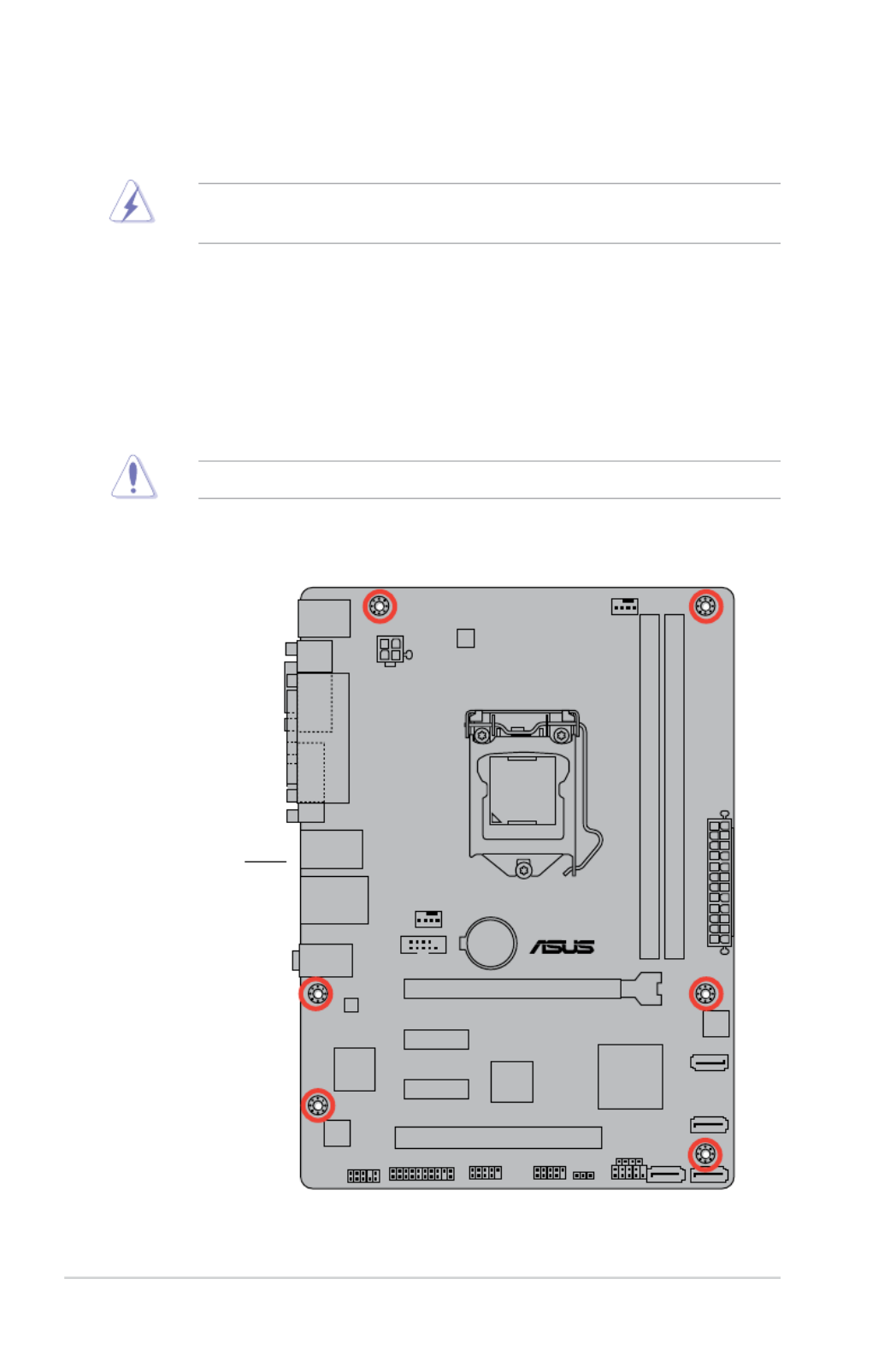
1.2.2 Screw holes
Place six screws into the holes indicated by circles to secure the motherboard to the chassis.
Donotovertightenthescrews!Doingsocandamagethemotherboard.
H81M-C R2.0
Place this side
towards the rear of
the chassis
1-2 Chapter 1: Product introduction

1.2.3 Motherboard layout
H81M-C R2.0
PCIEX16_1
PCIEX1_1
PCIEX1_2
PCI1
RTL
8111G
COM
AAFP
EATXPWR
CPU_FAN
BATTERY
Super
I/O
ALC
887-VD2
ASM
1083
KBMS
64Mb
BIOS
CLRTC
SPEAKER
17.8cm(7.0in)
DDR3 DIMM_A1 (64bit, 240-pin module)
DDR3 DIMM_B1 (64bit, 240-pin module)
SATA3G_2
SATA3G_1
SATA6G_1 SATA6G_2
AUDIO
LAN_USB34
USB3456
CHA_FAN
24.4cm(9.6in)
LGA1150
DIGI
+VRM
Intel ®
H81
ATX12V
F_PANEL
TPM USB910 USB1112
VGA
LPT
DVI
1 2 43 3
9 8 71013 12 11
1
5
6
Connectors/Jumpers/Slots/LED Page
1. ATXpowerconnectors(24-pinATXPWR,4-pinATX12V) 1-15
2. CPUandchassisfanconnectors(4-pinCPU_FAN,4-pinCHA_FAN) 1-18
3. Intel®LGA1150CPUsocket 1-4
4. DDR3DIMMslots 1-7
5. Intel®H81SerialATA3.0Gb/sconnector(7-pinSATA3G_1~2) 1-17
6. Speakerconnector(4-pinSPEAKER) 1-20
7. Intel®H81SerialATA6.0Gb/sconnector(7-pinSATA6G_1~2) 1-17
8. Systempanelconnector(10-1pinF_PANEL) 1-20
9. ClearRTCRAM(3-pinCLRTC) 1-12
10. USB2.0connectors(10-1pinUSB910,USB1112) 1-19
11. TPMheader(20-1pinTPM) 1-16
12. 1-19Serialportconnectors(10-1pinCOM)
13. Frontpanelaudioconnector(10-1pinAAFP) 1-16
ASUS H81M-C R2.0 1-3

UnplugallpowercablesbeforeinstallingtheCPU.
• Uponpurchaseofthemotherboard,ensurethatthePnPcapisonthesocket
andthesocketcontactsarenotbent.Contactyourretailerimmediatelyifthe
PnPcapismissing,orifyouseeanydamagetothePnPcap/socketcontacts/
motherboardcomponents.ASUSwillshoulderthecostofrepaironlyifthe
damageisshipment/transit-related.
• Keepthecapafterinstallingthemotherboard.ASUSwillprocessReturn
MerchandiseAuthorization(RMA)requestsonlyifthemotherboardcomeswith
thecapontheLGA1150socket.
• Theproductwarrantydoesnotcoverdamagetothesocketcontactsresulting
fromincorrectCPUinstallation/removal,ormisplacement/loss/incorrectremoval
of the PnP cap.
1.3 Central Processing Unit (CPU)
ThismotherboardcomeswithasurfacemountLGA1150socketdesignedfortheIntel
®4th/5th
generationCore™i7/Core™i5/Core™i3,Pentium® ,andCeleron® processors.
H81M- C R2.0
H81M-C R2.0 CPU socket LGA1150
1-4 Chapter 1: Product introduction

1.3.1 Installing the CPU
1
23
5
4
A
B
A
B
C
ASUS H81M-C R2.0 1-5

1.3.2 CPU heatsink and fan assembly installation
ApplytheThermalInterface
MaterialtotheCPUheatsink
andCPUbeforeyouinstallthe
heatsink and fan if necessary.
3 4
To install the CPU heatsink and fan assembly
2
B
A
A
B
1
1-6 Chapter 1: Product introduction
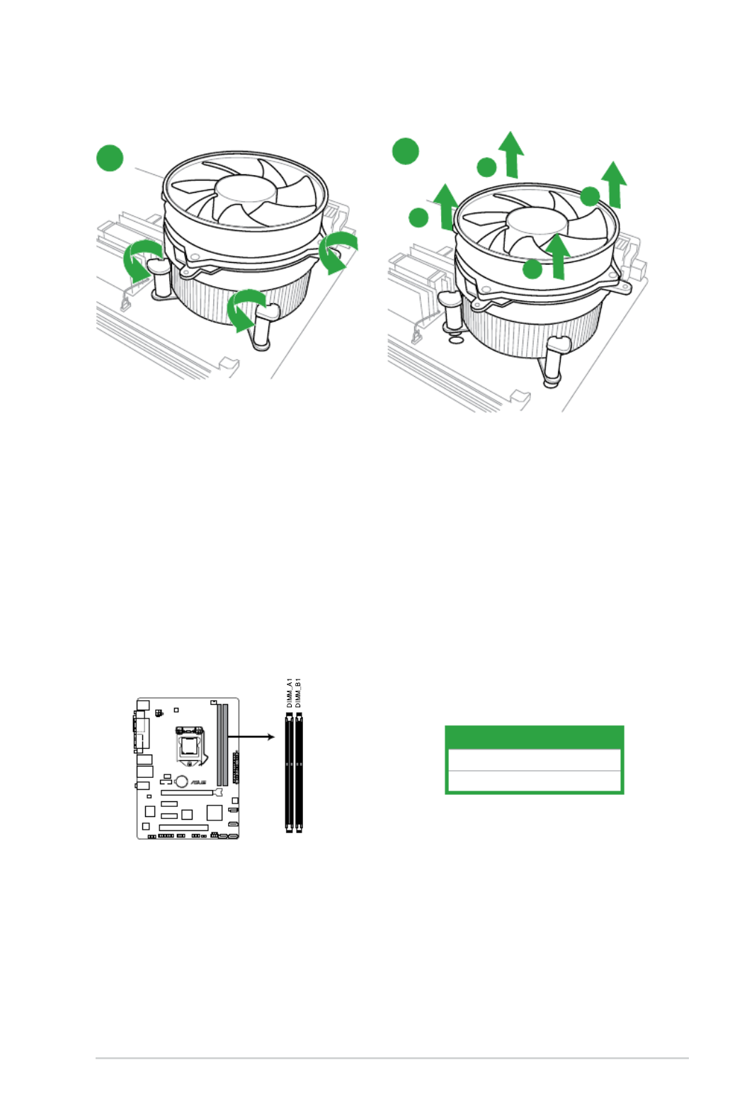
A
B
B
A
To uninstall the CPU heatsink and fan assembly
2
1
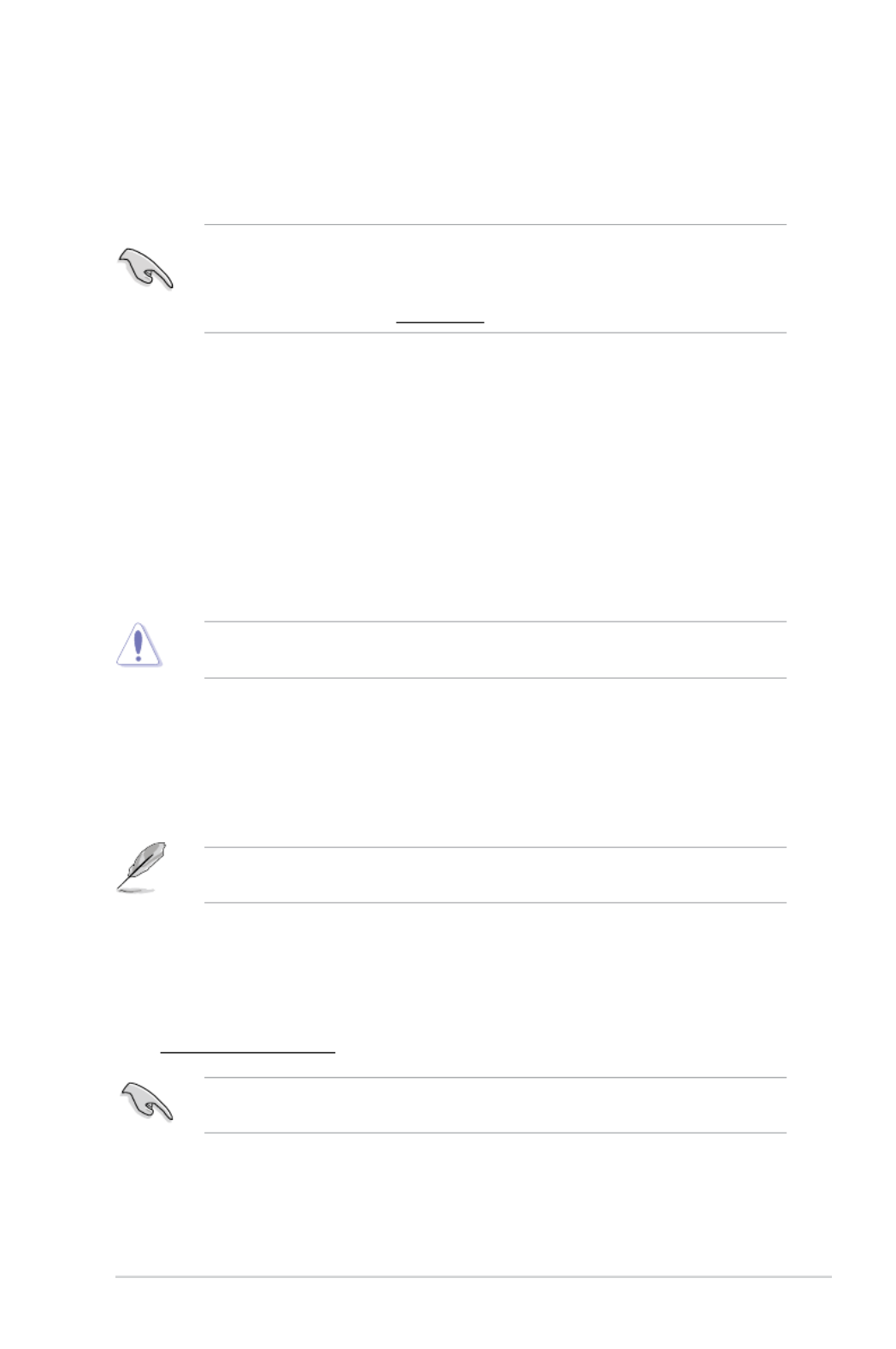
1.4 System memory
1.4.1 Overview
ThismotherboardcomeswithtwoDoubleDataRate3(DDR3)DualInlineMemoryModules(DIMM)
sockets.
ADDR3modulehasthesamephysicaldimensionsasaDDR2DIMMbutisnotcheddierentlyto
preventinstallationonaDDR2DIMMsocket.DDR3modulesaredevelopedforbetterperformance
with less power consumption.
Channel Sockets
ChannelA DIMM_A1
ChannelB DIMM_B1
H81M- C R2.0
H81M-C R2.0 240-pin DDR3 DIMM sockets
ASUS H81M-C R2.0 1-7

1.4.2 Memory configurations
Youmayinstall1GB,2GB,4GB,and8GBunbuerednon-ECCDDR3DIMMsintotheDIMMsockets.
• YoumayinstallvaryingmemorysizesinChannelAandChannelB.The
systemmapsthetotalsizeofthelower-sizedchannelforthedual-channel
conguration.Anyexcessmemoryfromthehigher-sizedchannelisthen
mapped for single-channel operation.
• AlwaysinstallDIMMswiththesameCASlatency.Foroptimalcompatibility,we
recommendthatyouinstallmemorymodulesofthesameversionordatecode
(D/C)fromthesamevendor.Checkwiththeretailertogetthecorrectmemory
modules.
• Memorymodulewithmemoryfrequencyhigherthan2133MHzandits
correspondingtimingortheloadedXMPProleisnottheJEDECmemory
standard. The stability and compatibility of these memory modules depend on
theCPU'scapabilitiesandotherinstalleddevices.
• DuetoIntel®chipsetlimitation,DDR31600MHzandhighermemorymodules
onXMPmodewillrunatthemaximumtransferrateofDDR31600MHz.
• Duetothememoryaddresslimitationon32-bitWindows®OS,whenyouinstall
4GBormorememoryonthemotherboard,theactualusablememoryfortheOS
canbeabout3GBorless.Foreectiveuseofmemory,werecommendthatyou
do any of the following:
-Useamaximumof3GBsystemmemoryifyouareusinga32-bitWindows®OS.
-Installa64-bitWindows®OSwhenyouwanttoinstall4GBormoreonthe
motherboard.
• ThismotherboarddoesnotsupportDIMMsmadeupof512Mb(64MB)chipsor
less.
• ThedefaultmemoryoperationfrequencyisdependentonitsSerialPresence
Detect(SPD),whichisthestandardwayofaccessinginformationfromamemory
module.Underthedefaultstate,somememorymodulesforoverclockingmay
operateatalowerfrequencythanthevendor-markedvalue.Tooperateatthe
vendor-markedoratahigherfrequency,refertosection2.4 Ai Tweaker menu
formanualmemoryfrequencyadjustment.
• Forsystemstability,useamoreecientmemorycoolingsystemtosupporta
fullmemoryload(2DIMMs)oroverclockingcondition.
1-8 Chapter 1: Product introduction

1.4.3 Installing a DIMM
To install a DIMM
1
2
3
To remove a DIMM
B
A
A
ASUS H81M-C R2.0 1-9

1.5 Expansion slots
Inthefuture,youmayneedtoinstallexpansioncards.Thefollowingsub-sectionsdescribetheslots
and the expansion cards that they support.
Unplugthepowercordbeforeaddingorremovingexpansioncards.Failuretodoso
may cause you physical injury and damage motherboard components.
1.5.1 Installing an expansion card
To install an expansion card:
1. Beforeinstallingtheexpansioncard,readthedocumentationthatcamewithit
and make the necessary hardware settings for the card.
2. Removethesystemunitcover(ifyourmotherboardisalreadyinstalledina
chassis).
3. Removethebracketoppositetheslotthatyouintendtouse.Keepthescrewfor
later use.
4. Alignthecardconnectorwiththeslotandpressrmlyuntilthecardiscompletely
seated on the slot.
5. Securethecardtothechassiswiththescrewyouremovedearlier.
6. Replacethesystemcover.
1.5.2 Configuring an expansion card
Afterinstallingtheexpansioncard,congureitbyadjustingthesoftwaresettings.
1. TurnonthesystemandchangethenecessaryBIOSsettings,ifany.SeeChapter2
forinformationonBIOSsetup.
2. AssignanIRQtothecard.
3. Installthesoftwaredriversfortheexpansioncard.
WhenusingPCIcardsonsharedslots,ensurethatthedriverssupport“ShareIRQ”or
thatthecardsdonotneedIRQassignments.Otherwise,conictswillarisebetween
thetwoPCIgroups,makingthesystemunstableandthecardinoperable.
1.6.3 PCI Express 2.0 p18-x1 slots
ThismotherboardsupportsPCIExpress2.0x1networkcards,SCSIcards,andothercardsthat
complywiththePCIExpressspecications.
1.6.4 PCI Express 3.0/2.0 x16 slot
ThismotherboardhasaPCIExpress3.0/2.0x16slotthatsupportsPCIExpress3.0/2.0x16graphic
cardscomplyingwiththePCIExpressspecications.
PCIe3.0speedissupportedbyIntel®3rdgenerationCore™processors.
1-10 Chapter 1: Product introduction

IRQ assignments for this motherboard
A B C D E F G H
PCIEx16 shared – – – – – – –
PCIEx1_1 – – – shared – – – –
PCIEx1_2 shared – – – – – – –
Realtek8111Fcontroller – shared – – – – – –
USB2.0controller1 – – – – – – – shared
USB2.0controller2 – – – – – – – shared
HDaudio – – – – – – shared –
SATAcontroller1 – – – shared – – – –
SATAcontroller2 – – – shared – – – –
ASUS H81M-C R2.0 1-11

To erase the RTC RAM:
1. TurnOFFthecomputerandunplugthepowercord.
2. Movethejumpercapfrompins1-2(default)topins2-3.Keepthecaponpins
2-3forabout5-10seconds,thenmovethecapbacktopins1-2.
3. PlugthepowercordandturnONthecomputer.
4. Holddownthe< >keyduringthebootprocessandenterBIOSsetuptoDel
re-enter data.
ExceptwhenclearingtheRTCRAM,neverremovethecaponCLRTCjumperdefault
position.Removingthecapwillcausesystembootfailure!
• Ifthestepsabovedonothelp,removetheonboardbatteryandmovethe
jumperagaintocleartheCMOSRTCRAMdata.AfterclearingtheCMOS,reinstall
the battery.
• YoudonotneedtocleartheRTCwhenthesystemhangsduetooverclocking.
Forsystemfailureduetooverclocking,usetheCPUParameterRecall(C.P.R.)
feature.Shutdownandrebootthesystem,thentheBIOSautomaticallyresets
parametersettingstodefaultvalues.
1.6 Jumpers
Clear RTC RAM (3-pin CLRTC)
ThisjumperallowsyoutocleartheRealTimeClock(RTC)RAMinCMOS.Youcanclearthe
CMOSmemoryofdate,time,andsystemsetupparametersbyerasingtheCMOSRTCRAM
data.TheonboardbuttoncellbatterypowerstheRAMdatainCMOS,whichincludesystem
setup information such as system passwords.
H81M- C R2.0
H81M-C R2.0 Clear RTC RAM
1-12 Chapter 1: Product introduction

1.7 Connectors
1.7.1 Rear panel connectors
1. PS/2 mouse port (green).ThisportisforaPS/2mouse.
2. Parallel port.This25-pinportconnectsaparallelprinter,ascanner,orother
devices.
3. USB 2.0 ports.These4-pinUniversalSerialBus(USB)portsareforUSB2.0/1.1
devices.
4. LAN (RJ-45) port.ThisportallowsGigabitconnectiontoaLocalAreaNetwork
(LAN)throughanetworkhub.
LAN port LED indications
5. Line In port (light blue).Thisportconnectstothetape,CD,DVDplayer,orother
audio sources.
6. Line Out port (lime).Thisportconnectstoaheadphoneoraspeaker.Inthe
4.1,5.1and7.1-channelcongurations,thefunctionofthisportbecomesFront
SpeakerOut.
7. Microphone port (pink). This port connects to a microphone.
Refertotheaudiocongurationtableforthefunctionoftheaudioportsin2.1,4.1,
5.1,or7.1-channelconguration.
LAN port
Speed
LED
Activity Link
LED
Activity/Link LED Speed LED
Status Description Status Description
O Nolink OFF 10Mbpsconnection
Orange ORANGE 100MbpsconnectionLinked
Orange(Blinking) Dataactivity GREEN 1Gbps connection
Orange(Blinking
thensteady)
Readytowakeup
fromS5mode
ASUS H81M-C R2.0 1-13

To configure a 7.1-channel audio output:
• UseachassiswithHDaudiomoduleinthefrontpaneltosupporta7.1-channel
audio output.
8. USB 3.0 ports 1 and 2.Thesetwo9-pinUniversalSerialBus(USB)portsarefor
USB3.0devices.
• DONOTconnectakeyboard/mousetoanyUSB3.0portwheninstalling
Windows® operating system.
• DuetoUSB3.0controllerlimitations,USB3.0devicescanonlybeusedundera
Windows®OSenvironmentandafterUSB3.0driverinstallation.
• USB3.0devicescanonlybeusedfordatastorage.
• WestronglyrecommendthatyouconnectUSB3.0devicestoUSB3.0portsfor
fasterandbetterperformancefromyourUSB3.0devices.
9. Video Graphics Adapter (VGA) port.This15-pinportisforaVGAmonitoror
otherVGA-compatibledevices.
10. DVI-D port. ThisportisforanyDVI-Dcompatibledevice.DVI-Dcannotbe
convertedtooutputRGBSignaltoCRTandisnotcompatiblewithDVI-I.
WhenyouuseaDVI-to-HDMIadapter,settheDVI Port Audio Enabled item to [ ]
in Advanced System Agent Configuration DVI Port Audio > > oftheBIOSSetup
programanduninstallthenreinstalltheVGAdrivertogetanaudiooutput.
11. PS/2 keyboard port (purple).ThisportisforaPS/2keyboard.
Audio 2.1, 4.1, 5.1, or 7.1-channel configuration
Port Headset
2.1-channel 4.1-channel 5.1-channel 7.1-channel
LightBlue(Rear
panel) LineIn RearSpeakerOut RearSpeakerOut RearSpeakerOut
Lime(Rearpanel) LineOut FrontSpeakerOut FrontSpeakerOut FrontSpeakerOut
Pink(Rearpanel) MicIn MicIn Bass/Center Bass/Center
Lime(Frontpanel) SideSpeakerOut- - -
1-14 Chapter 1: Product introduction

•
Forafullyconguredsystem,werecommendthatyouuseapowersupplyunit
(PSU)thatcomplieswithATX12VSpecication2.0(orlaterversion)andprovides
aminimumpowerof350W.
•
DONOTforgettoconnectthe4-pinATX+12Vpowerplug.Otherwise,the
system will not boot up.
• WerecommendthatyouuseaPSUwithhigherpoweroutputwhenconguring
asystemwithmorepower-consumingdevicesorwhenyouintendtoinstall
additionaldevices.Thesystemmaybecomeunstableormaynotbootupifthe
powerisinadequate.
•
Ifyouareuncertainabouttheminimumpowersupplyrequirementforyour
system,refertotheRecommendedPowerSupplyWattageCalculatorathttp://
support.asus.com/PowerSupplyCalculator/PSCalculator.aspx?SLanguage=en-us
for details.
1.7.2 Internal connectors
1. ATX power connectors (24-pin EATXPWR, 4-pin ATX12V)
TheseconnectorsareforATXpowersupplyplugs.Thepowersupplyplugsaredesignedtot
theseconnectorsinonlyoneorientation.Findtheproperorientationandpushdownrmly
untiltheconnectorscompletelyt.
H81M- C R2.0
H81M-C R2.0 ATX power connectors
ASUS H81M-C R2.0 1-15

2. TPM connector (20-1 pin TPM)
ThisconnectorsupportsaTrustedPlatformModule(TPM)system,whichsecurelystorekeys,
digitalcerticates,passwordsanddata.ATPMsystemalsohelpsenhancenetworksecurity,
protectdigitalidentities,andensuresplatformintegrity.
TheTPMmoduleispurchasedseparately.
3. Front panel audio connector (10-1 pin AAFP)
Thisconnectorisforachassis-mountedfrontpanelaudioI/Omodulethatsupportseither
HDAudioorlegacyAC`97audiostandard.ConnectoneendofthefrontpanelaudioI/O
module cable to this connector.
• Werecommendthatyouconnectahigh-denitionfrontpanelaudiomoduleto
thisconnectortoavailofthemotherboard’shigh-denitionaudiocapability.
• Ifyouwanttoconnectahigh-denitionfrontpanelaudiomoduletothis
connector,settheFrontPanelTypeitemintheBIOSsetupto[HD].Ifyouwant
toconnectanAC’97frontpanelaudiomoduletothisconnector,settheitem
to[AC97].Bydefault,thisconnectorissetto[HD].Seesection2.6.7 Onboard
Devices Configuration for details.
H81M-C R2.0
H81M-C R2.0 TPM Connector
H81M- C R2.0
H81M-C R2.0 Front panel audio connector
1-16 Chapter 1: Product introduction

4. Intel® H81 Serial ATA 6.0Gb/s connector (7-pin SATA6G_1~2 [yellow])
ThisconnectorconnectstoSerialATA6.0Gb/sharddiskdrivesviaSerialATA6.0Gb/ssignal
cables.
•YoumustinstallWindows.XPServicePack3orlaterversionbeforeusingSerialATA
harddiskdrives.
•Whenusinghot-plugandNCQ,settheSATA Mode SelectionitemintheBIOSto
[AHCI].Seesection2.6.3 SATA Configuration for details.
5. Intel® H81 Serial ATA 3.0Gb/s connector (7-pin SATA3G_1~2)
ThisconnectorconnectstoSerialATA3.0Gb/sharddiskdrivesviaSerialATA3.0Gb/ssignal
cables.
H81M- C R2.0
H81M-C R2.0 SATA 6.0Gb/s connectors
•YoumustinstallWindows.XPServicePack3orlaterversionbeforeusingSerialATA
harddiskdrives.
•Whenusinghot-plugandNCQ,settheSATA Mode SelectionitemintheBIOSto
[AHCI].
H81M- C R2.0
H81M-C R2.0 SATA 3.0Gb/s connectors
ASUS H81M-C R2.0 1-17

6. CPU and chassis fan connectors (4-pin CPU_FAN, 4-pin CHA_FAN)
Connectthefancablestothefanconnectorsonthemotherboard,ensuringthattheblack
wire of each cable matches the ground pin of the connector.
Donotforgettoconnectthefancablestothefanconnectors.Insucientairow
inside the system may damage the motherboard components. These are not
jumpers!Donotplacejumpercapsonthefanconnectors!TheCPU_FANconnector
supportsaCPUfanofmaximum1A(12W)fanpower.
Onlythe4-pinCPUfansupportstheASUSFanXpert2feature.
CHA_FAN
H81M- C R2.0
H81M-C R2.0 Fan connectors
1-18 Chapter 1: Product introduction

7. USB 2.0 connectors (10-1 pin USB910, USB1112)
TheseconnectorsareforUSB2.0ports.ConnecttheUSBmodulecabletoanyofthese
connectors,theninstallthemoduletoaslotopeningatthebackofthesystemchassis.These
USBconnectorscomplywithUSB2.0specicationsandsupportsupto480Mbpsconnection
speed.
Neverconnecta1394cabletotheUSBconnectors.Doingsowilldamagethe
motherboard!
TheUSB2.0moduleispurchasedseparately.
8. Serial port connector (10-1 pin COM)
Thisconnectorisforaserial(COM)port.Connecttheserialportmodulecabletothis
connector,theninstallthemoduletoaslotopeningatthebackofthesystemchassis.
H81M-C R2.0
H81M-C R2.0 USB2.0 connectors
PIN 1
USB+5V
USB_P9-
USB_P9+
GND
NC
USB+5V
USB_P10-
USB_P10+
GND
USB910 USB1112
PIN 1
USB+5V
USB_P11-
USB_P11+
GND
NC
USB+5V
USB_P12-
USB_P12+
GND
TheCOMmoduleispurchasedseparately.
H81M-C R2.0
H81M-C R2.0 Serial port connectors
PIN 1
COM
DCD
TXD
GND
RTS
RI
RXD
DTR
DSR
CTS
ASUS H81M-C R2.0 1-19

9. System panel connector (10-1 pin PANEL)
Thisconnectorsupportsseveralchassis-mountedfunctions.
• SystempowerLED(2-pinPWR_LED)
This2-pinconnectorisforthesystempowerLED.ConnectthechassispowerLEDcableto
thisconnector.ThesystempowerLEDlightsupwhenyouturnonthesystempower,and
blinks when the system is in sleep mode.
• HarddiskdriveactivityLED(2-pinHDD_LED)
This2-pinconnectorisfortheHDDActivityLED.ConnecttheHDDActivityLEDcabletothis
connector.TheHDDLEDlightsuporasheswhendataisreadfromorwrittentotheHDD.
• ATXpowerbutton/soft-obutton(2-pinPWR_BTN)
This connector is for the system power button.
• Resetbutton(2-pinRESET)
This 2-pin connector is for the chassis-mounted reset button for system reboot without
turning off the system power.
10. Speaker connector (4-pin SPEAKER)
The4-pinconnectorisforthechassis-mountedsystemwarningspeaker.Thespeakerallows
you hear system beeps and warnings.
H81M-C R2.0
PIN 1
PWR BTN
PWR_LED+
PWR_LED-
PWR
GND
HDD_LED+
HDD_LED-
Ground
HWRST#
(NC)
F_PANEL
+PWR LED
+HDD_LED RESET
H81M-C R2.0 System panel connector
H81M-C R2.0
H81M-C R2.0 System panel connector
+5V
GND
GND
Speaker Out
SPEAKER
PIN 1
1-20 Chapter 1: Product introduction

1.8 Software support
1.8.1 Installing an operating system
ThismotherboardsupportsWindows ®
XP/Windows
®
Vista/Windows
®
7/Windows
®
8Operating
Systems(OS).AlwaysinstallthelatestOSversionandcorrespondingupdatestomaximizethe
features of your hardware.
• Motherboardsettingsandhardwareoptionsvary.RefertoyourOS
documentation for detailed information.
• EnsurethatyouinstallWindows
®
XPServicePack3orlaterversions/Windows
®
VistaServicePack1orlaterversionsbeforeinstallingthedriversforbetter
compatibility and system stability.
1.8.2 Support DVD information
TheSupportDVDthatcomeswiththemotherboardpackagecontainsthedrivers,software
applications,andutilitiesthatyoucaninstalltoavailallmotherboardfeatures.
ThecontentsoftheSupportDVDaresubjecttochangeatanytimewithoutnotice.
VisittheASUSwebsiteatwww.asus.com for updates.
To run the Support DVD
PlacetheSupportDVDintotheopticaldrive.IfAutorunisenabledinyourcomputer,theDVD
automaticallydisplaystheSpecialsscreen.ClickDrivers,Utilities,MakeDisk,Manual,andContact
tabstodisplaytheirrespectivemenus.
The following screen is for reference only.
IfAutorunisNOTenabledonyourcomputer,browsethecontentsoftheSupport
DVDtolocatetheleASSETUP.EXEfromtheBINfolder.Double-clicktheASSETUP.EXE
toruntheDVD.
Click an item to install
Click an icon to
display Support DVD/
motherboard information
ASUS H81M-C R2.0 1-21

1-22 Chapter 1: Product introduction

ASUS H81M-C R2.0 2-1
2.1 Managing and updating your BIOS
Save a copy of the original motherboard BIOS le to a USB ash disk in case you need to restore
the BIOS in the future. Copy the original motherboard BIOS using the ASUS Update utility.
2.1.1 EZ Update
EZ Update is a utility that allows you to automatically update your motherboard’s softwares, drivers
and the BIOS version easily. With this utlity, you can also manually update the saved BIOS and select
a boot logo when the system goes into POST.
To launch EZ Update, click EZ Update on the AI Suite 3 main menu bar.
BIOS information
2
Click to automatically
update your
motherboard’s driver,
software and rmware
Click to nd and select
the BIOS from le
Click to select a
boot logo
Click to update
the BIOS
EZ Update requires an Internet connection either through a network or an ISP (Internet Service
Provider).

2-2 Chapter 2: BIOS information
2.1.2 ASUS EZ Flash 2
The ASUS EZ Flash 2 feature allows you to update the BIOS without using an OS-based utility.
Before you start using this utility, download the latest BIOS le from the ASUS website at www.
asus.com.
To update the BIOS using EZ Flash 2:
1. Insert the USB ash disk that contains the latest BIOS le to the USB port.
2. Enter the Advanced Mode Tool of the BIOS setup program. Go to the menu to select ASUS
EZ Flash Utility and press <Enter> to enable it.
3. Press <Tab> to switch to the Drive eld.
4. Press the Up/Down arrow keys to nd the USB ash disk that contains the latest BIOS, and
then press <Enter>.
5. Press <Tab> to switch to the Folder Info eld.
6. Press the Up/Down arrow keys to nd the BIOS le, and then press <Enter> to perform the
BIOS update process. Reboot the system when the update process is done.
• ThisfunctionsupportsUSBashdisksformattedusingFAT32/16onasinglepartitiononly.
• EnsuretoloadtheBIOSdefaultsettingstoensuresystemcompatibilityandstability.Select
the Load Optimized Defaults item under the Exit menu. .
• DONOTshutdownorresetthesystemwhileupdatingtheBIOStopreventsystemboot
failure!
ASUS H81M-C R2.0 2-3
2.1.3 ASUS CrashFree BIOS 3 utility
The ASUS CrashFree BIOS 3 is an auto recovery tool that allows you to restore the BIOS le when it
fails or gets corrupted during the updating process. You can restore a corrupted BIOS le using the
motherboard support DVD or a USB ash drive that contains the updated BIOS le.
• Beforeusingthisutility,renametheBIOSleintheremovabledeviceinto
H81M-C-R2.CAP.
• TheBIOSleinthesupportDVDmaynotbethelatestversion.DownloadthelatestBIOSle
from the ASUS website at www.asus.com.
Recovering the BIOS
To recover the BIOS:
1. Turn on the system.
2. Insert the support DVD to the optical drive or the USB ash drive that contains the BIOS le
to the USB port.
3. The utility automatically checks the devices for the BIOS le. When found, the utility reads
the BIOS le and enters ASUS EZ Flash 2 utility automatically.
4. The system requires you to enter BIOS Setup to recover BIOS settings. To ensure system
compatibility and stability, we recommend that you press <F5> to load default BIOS values.
DONOTshutdownorresetthesystemwhileupdatingtheBIOS!Doingsocancausesystemboot
failure!
2.1.4 ASUS BIOS Updater
The ASUS BIOS Updater allows you to update BIOS in a DOS environment. This utility also allows
you to copy the current BIOS le that you can use as a backup when the BIOS fails or gets corrupted
during the updating process.
The succeeding utility screens are for reference only. The actual utility screen displays may not be
same as shown.
Before updating BIOS
1. Prepare the motherboard support DVD and a USB ash drive formatted using FAT32/16 on a
single partition.
2. Download the latest BIOS le and BIOS Updater from the ASUS website at
http://support.asus.com and save them on the USB ash drive.
NTFSisnotsupportedunderDOSenvironment.DonotsavetheBIOSleandBIOSUpdatertoa
harddiskdriveorUSBashdriveinNTFSformat.
3. Turn off the computer and disconnect all SATA hard disk drives (optional).

2-4 Chapter 2: BIOS information
Booting the system to a DOS environment
1. Insert the DOS-bootable USB ash drive with the latest BIOS le and BIOS Updater to your
computer’s USB port.
2. Boot your computer. When the ASUS Logo appears, press <F8> to show the BIOS Boot
Device Select Menu.
3. Select the optical drive as the boot device. The DOS screen appears.
Updating the BIOS le
To update the BIOS le using BIOS Updater:
1. At the FreeDOS prompt, type and press <Enter>.bupdater /pc /g
2. The BIOS Updater screen appears as below.
0705
H81M-C-R2.CAP 8390656 2012-02-01 15:25:48
06/08/2013
H81M-C R2.0
ASUSTek BIOS Updater for DOS V1.30

ASUS H81M-C R2.0 2-5
3. Press <Tab> to switch between screen elds and use the <Up/Down/Home/End> keys
to select the BIOS le and press <Enter>. BIOS Updater checks the selected BIOS le and
prompts you to conrm BIOS update.
4. Select Yes and press <Enter>. When BIOS update is done, press <ESC> to exit BIOS Updater.
Restart your computer.
DONOTshutdownorresetthesystemwhileupdatingtheBIOStopreventsystembootfailure!
• ForBIOSUpdaterversion1.30orlater,theutilityautomaticallyexitstotheDOSpromptafter
updating BIOS.
• EnsuretoloadtheBIOSdefaultsettingstoensuresystemcompatibilityandstability.Select
the Load Optimized Defaults item under the Exit menu. Refer to section for 2.10 Exit menu
details.
• EnsuretoconnectallSATAharddiskdrivesafterupdatingtheBIOSleifyouhave
disconnected them.

2-6 Chapter 2: BIOS information
2.2 BIOS setup program
Use the BIOS Setup program to update the BIOS or congure its parameters. The BIOS screens
include navigation keys and brief online help to guide you in using the BIOS Setup program.
Entering BIOS Setup at startup
To enter BIOS Setup at startup:
• Press <Delete> during the Power-On Self Test (POST). If you do not press <Delete>, POST
continues with its routines.
Entering BIOS Setup after POST
To enter BIOS Setup after POST:
• Press <Ctrl>+<Alt>+<Del> simultaneously.
• Press the reset button on the system chassis.
• Press the power button to turn the system off then back on. Do this option only if you failed to
enter BIOS Setup using the rst two options.
Using the power button, reset button, or the <Ctrl>+<Alt>+<Del> keys to force reset from a
running operating system can cause damage to your data or system. We recommend you always
shut down the system properly from the operating system.
• TheBIOSsetupscreensshowninthissectionareforreferencepurposesonly,andmaynot
exactly match what you see on your screen.
• VisittheASUSwebsiteatwww.asus.com to download the latest BIOS le for this
motherboard.
• EnsurethataUSBmouseisconnectedtoyourmotherboardifyouwanttousethemouseto
control the BIOS setup program.
• IfthesystembecomesunstableafterchanginganyBIOSsetting,loadthedefaultsettingsto
ensure system compatibility and stability. Select the item under Load Optimized Defaults
the Exit menu or press hotkey F5. See section for details.2.10 Exit Menu
• IfthesystemfailstobootafterchanginganyBIOSsetting,trytocleartheCMOSandreset
the motherboard to the default value. See section for information on how to 1.6 Jumpers
erasetheRTCRAM.
BIOS menu screen
The BIOS setup program can be used under two modes: and EZ Mode Advanced Mode. You
can change modes from the ExitmenuorfromtheExit/AdvancedModebuttonintheEZMode/
AdvancedModescreen.
ASUS H81M-C R2.0 2-7
• Thebootdeviceoptionsvarydependingonthedevicesyouinstalledtothesystem.
• TheBoot Menu(F8) button is available only when the boot device is installed to the system.
Advanced Mode
TheAdvancedModeprovidesadvancedoptionsforexperiencedend-userstocongurethe
BIOS settings. The gure below shows an example of the Advanced Mode. Refer to the following
sections for the detailed congurations.
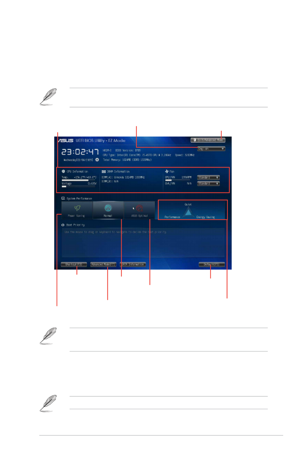
ToaccesstheEZMode,clickExit ASUS EZ Mode F7., then select or press
Displays the system
properties of the selected
mode on the right hand
side
Normal mode Loads
optimized
default
Displays the CPU/motherboard
temperature, CPU voltage output,
and CPU/chassis fan speed
Selects the display language of
the BIOS setup program
Exits the BIOS setup program without saving
the changes, saves the changes and resets the
system, or enters the Advanced Mode
ASUS Optimal
mode
Displays the
Advanced mode
menus
Selects the
Advanced mode
functions
Power saving
mode
EZ Mode
Bydefault,theEZModescreenappearswhenyouentertheBIOSsetupprogram.TheEZMode
provides you an overview of the basic system information, and allows you to select the display
language,systemperformancemodeandbootdevicepriority.ToaccesstheAdvancedMode,click
Exit/AdvancedMode,thenselectAdvancedModeorpressF7fortheadvancedBIOSsettings.
The default screen for entering the BIOS setup program can be changed. Refer to the Setup
Mode 2.8 Boot menu item in section for details.
2-8 Chapter 2: BIOS information
Navigation keys
General helpMenu bar
Submenu item
Conguration eldsMenu itemsBack button
Pop-up window
Scroll bar
Menu items
The highlighted item on the menu bar displays the specic items for that menu. For example,
selecting MainshowstheMainmenuitems.
Theotheritems(AiTweaker,Advanced,Monitor,Boot,Tool,andExit)onthemenubarhavetheir
respective menu items.
Back button
This button appears when entering a submenu. Press <Esc> or use the USB mouse to click this
button to return to the previous menu screen.
Last modied
settings Quick note
Menu bar
The menu bar on top of the screen has the following main items:
My Favorites For saving the frequently-used system settings and conguration
Main For changing the basic system conguration
Ai Tweaker For changing the overclocking settings
Advanced For changing the advanced system settings
Monitor For displaying the system temperature, power status, and changing the fan
settings
Boot For changing the system boot conguration
Tool For conguring options for special functions
Exit For selecting the exit options and loading default settings

ASUS H81M-C R2.0 2-9
Submenu items
A greater than sign (>) before each item on any menu screen means that the item has a submenu.
To display the submenu, select the item and press <Enter>.
Pop-up window
Select a menu item and press <Enter> to display a pop-up window with the conguration options
for that item.
Scroll bar
A scroll bar appears on the right side of a menu screen when there are items that do not t on the
screen. Press the Up/Down arrow keys or <Page Up> / <Page Down> keys to display the other items
on the screen.
Navigation keys
At the bottom right corner of the menu screen are the navigation keys for the BIOS setup program.
Use the navigation keys to select items in the menu and change the settings.
For the navigation key, it’s only available in English. If you delete the default shortcuts, they will
appear on your next system bootup.
General help
At the top right corner of the menu screen is a brief description of the selected item.
Conguration elds
These elds show the values for the menu items. If an item is user-congurable, you can change the
value of the eld opposite the item. You cannot select an item that is not
user-congurable.
A congurable eld is highlighted when selected. To change the value of a eld, select it and press
<Enter> to display a list of options.
Quick Note button
This button allows you to enter notes of the activities that you have done in BIOS.
• TheQuickNotefunctiondoesnotsupportthefollowingkeyboardfunctions:delete,cut,
copy and paste.
• YoucanonlyusetheEnglishletterstotypeyournotes.
Last Modied button
This button shows the items that you last modied and saved in BIOS Setup.
2-10 Chapter 2: BIOS information
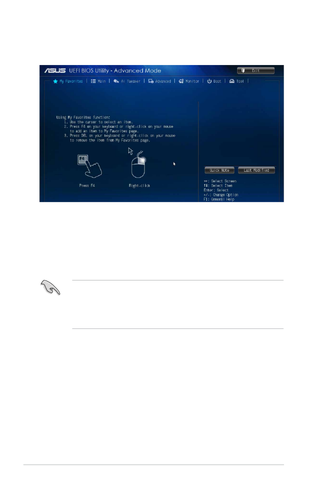
Adding items to My Favorites
Toaddfrequently-usedBIOSitemstoMyFavorites:
1. Use the arrow keys to select an item that you want to add. When using a mouse, hover the
pointer to the item.
2. Press<F4>onyourkeyboardorright-clickonyourmousetoaddtheitemtoMyFavorites
page.
YoucannotaddthefollowingitemstoMyFavorites:
• Itemswithsubmenuoptions
• User-congurableitemssuchaslanguageandbootdeviceorder
• CongurationitemssuchasMemorySPDInformation,systemtimeanddate
2.3 My Favorites
MyFavoritesisyourpersonalspacewhereyoucaneasilysaveandaccessyourfavorite
BIOS items.
ASUS H81M-C R2.0 2-11
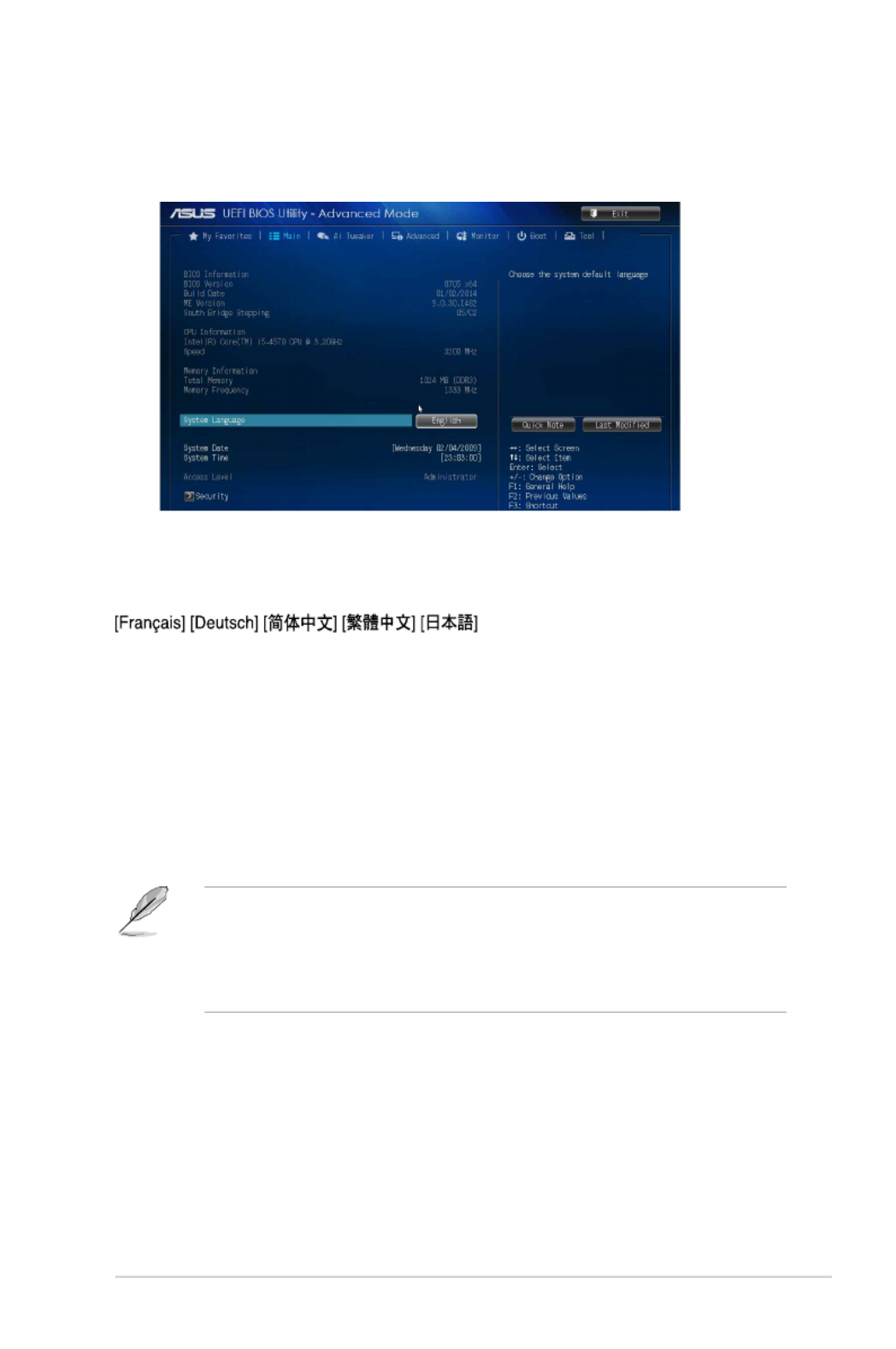
2.4 Main menu
TheMainmenuscreenappearswhenyouentertheAdvancedModeoftheBIOSSetupprogram.
TheMainmenuprovidesyouanoverviewofthebasicsysteminformation,andallowsyoutoset
the system date, time, language, and security settings.
2.4.1 System Language [English]
Allows you to choose the BIOS language version from the options. Conguration options: [English]
[Español] [Русский] [
]
2.4.2 System Date [Day xx/xx/xxxx]
Allows you to set the system date.
2.4.3 System Time [xx:xx:xx]
Allows you to set the system time.
2.4.4 Security
The Security menu items allow you to change the system security settings.
• IfyouhaveforgottenyourBIOSpassword,erasetheCMOSRealTimeClock(RTC)RAMto
clear the BIOS password. See section for information on how to erase the RTC 1.6 Jumpers
RAM.
• TheAdministrator User Password Not or items on top of the screen show the default
Installed. After you set a password, these items show .Installed

2-12 Chapter 2: BIOS information
Administrator Password
If you have set an administrator password, we recommend that you enter the administrator
password for accessing the system. Otherwise, you might be able to see or change only selected
elds in the BIOS setup program.
To set an administrator password:
1. Select the Administrator Password item and press <Enter>.
2. From the Create New Password box, key in a password, then press <Enter>.
3. Conrm the password when prompted.
To change an administrator password:
1. Select the Administrator Password item and press <Enter>.
2. From the Enter Current Password box, key in the current password, then press <Enter>.
3. From the Create New Password box, key in a new password, then press <Enter>.
4. Conrm the password when prompted.
To clear the administrator password, follow the same steps as in changing an administrator
password, but press <Enter> when prompted to create/conrm the password. After you clear the
password, the Administrator Password item on top of the screen shows .Not Installed
User Password
If you have set a user password, you must enter the user password for accessing the system.
The User Password item on top of the screen shows the default . After you set a Not Installed
password, this item shows .Installed
To set a user password:
1. Select the User Password item and press <Enter>.
2. From the Create New Password box, key in a password, then press <Enter>.
3. Conrm the password when prompted.
To change a user password:
1. Select the User Password item and press <Enter>.
2. From the Enter Current Password box, key in the current password, then press <Enter>.
3. From the Create New Password box, key in a new password, then press <Enter>.
4. Conrm the password when prompted.
To clear the user password, follow the same steps as in changing a user password, but press <Enter>
when prompted to create/conrm the password. After you clear the password, the User Password
item on top of the screen shows .Not Installed
ASUS H81M-C R2.0 2-13
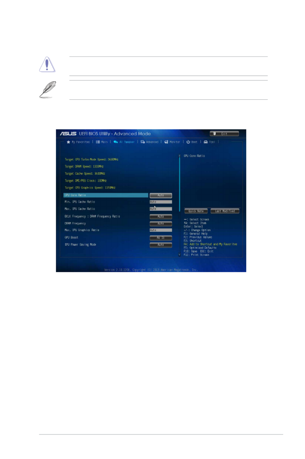
2.5 Ai Tweaker menu
The Ai Tweaker menu items allow you to congure overclocking-related items.
Be cautious when changing the settings of the Ai Tweaker menu items. Incorrect eld values can
cause the system to malfunction.
ThecongurationoptionsforthissectionvarydependingontheCPUandDIMMmodelyou
installed on the motherboard.
Scroll down to display the other items.
Target CPU Turbo-Mode Speed : xxxxMHz
DisplaysthetargetCPUTurbo-Modespeed.
Target DRAM Speed : xxxxMHz
DisplaysthetargetDRAMspeed.
Target Cache Speed : xxxxMHz
Displays the target Cache speed.
Target DMI/PEG Clock : xxxxMHz
DisplaysthetargetDMI/PEGclock.
Target CPU Graphics Speed : xxxxMHz
Displays the target iGPU speed.

2-14 Chapter 2: BIOS information
2.5.1 CPU Core Ratio [Auto]
Allows you to set the CPU core ratio automatically or manually.
[Auto] Sets all CPU Core Ratio to Intel
®
CPU default settings automatically.
[Sync All Cores] Allows you to set CPU Core Ratio settings for all cores.
[Per Core] Allows you to set CPU Core Ratio individually.
The following items appear only when you set the CPU Core Ratio to [Sync All Cores] [Per or
Core].
1-Core Ratio Limit [Auto]
Allows you to set the 1-Core Ratio Limit. Select [Auto] to apply the CPU default Turbo Ratio
setting or manually assign a 1-Core Ratio Limit value that is higher than or equal to the
2-Core Ratio Limit.
2-Core Ratio Limit [Auto]
This item becomes congurable only when you set to [Per Core] and allows CPU Core Ratio
you to set the 2-Core Ratio Limit. Select [Auto] to apply the CPU default Turbo Ratio setting
or manually assign a 2-Core Ratio Limit value that is higher than or equal to the 3-Core Ratio
Limit. 1-Core Limit must not be set to [Auto].
3-Core Ratio Limit [Auto]
This item becomes congurable only when you set to [Per Core] and allows CPU Core Ratio
you to set the 3-Core Ratio Limit. Select [Auto] to apply the CPU default Turbo Ratio setting
or manually assign a 3-Core Ratio Limit value that is higher than or equal to the 4-Core Ratio
Limit. 1-Core/2-Core Ratio Limit must not be set to [Auto].
4-Core Ratio Limit [Auto]
This item becomes congurable only when you set to [Per Core] and allows CPU Core Ratio
you to set the 4 Core Ratio Limit. Select [Auto] to apply the CPU default Turbo Ratio setting
or manually assign a 4-Core Ratio Limit value that is higher than or equal to the 3-Core Ratio
Limit. 1-Core/2-Core/3-Core Limit must not be set to [Auto].
2.5.2 Min CPU Cache Ratio [Auto]
Allows you to set the uncore ratio of the processor to its possible minimum value. Conguration
options:[Auto][1]~[30].
2.5.3 Max CPU Cache Ratio [Auto]
Allows you to set the uncore ratio of the processor to its possible maximum value. Conguration
options:[Auto][1]~[30].
2.5.4 BCLK Frequency : DRAM Frequency Ratio [Auto]
AllowsyoutosettheBCLKfrequencytoDRAMfrequencyratio.
[Auto] DRAMfrequencyissettotheoptimizedsettings.
[100:133] TheBCLKfrequencytoDRAMfrequencyratioissetto100:133.
[100:100] TheBCLKfrequencytoDRAMfrequencyratioissetto100:100.

ASUS H81M-C R2.0 2-15
2.5.5 DRAM Frequency [Auto]
Allows you to set the memory operating frequency. The conguration options vary with the BCLK/
PEG Frequency item settings.
Selecting a very high memory frequency may cause the system to become unstable! If this
happens, revert to the default setting.
2.5.6 Max. CPU Graphics Ratio [Auto]
[Auto] The iGPU frequency is set to its optimized setting depending on the system
loading.
[Manaul] Usethe<+>or<->keystoadjusttheoptimaliGPUfrequencyvalue.The
frequency may vary depending on the system loading.
2.5.7 GPU Boost [As is]
Allows you to enable the GPU Boost to accelerate the integrated GPU for extreme graphics
performance. Conguration options: [As is] [Enabled].
2.5.8 EPU Power Saving Mode [Auto]
Allows you to enable or disable the EPU power saving function. Conguration options: [Auto]
[Disabled] [Enabled]
2.5.9 DRAM Timing Control
ThesubitemsinthismenuallowyoutosettheDRAMtimingcontrolfeatures.Usethe<+>and<->
keystoadjustthevalue.Torestorethedefaultsetting,type[auto]usingthekeyboardandpressthe
<Enter> key.
Changing the values in this menu may cause the system to become unstable! If this happens,
revert to the default settings.
Primary Timings
DRAM CAS# Latency [Auto]
Congurationoptions:[Auto][1DRAMClock]–[31DRAMClock]
DRAM RAS# to CAS# Delay [Auto]
Congurationoptions:[Auto][1DRAMClock]–[31DRAMClock]
DRAM RAS# PRE Time [Auto]
Congurationoptions:[Auto][1DRAMClock]–[31DRAMClock]
DRAM RAS# ACT Time [Auto]
Congurationoptions:[Auto][1DRAMClock]–[63DRAMClock]
DRAM COMMAND Rate [Auto]
Congurationoptions:[Auto][1DRAMClock][2DRAMClock][3DRAMClock]

2-16 Chapter 2: BIOS information
Secondary Timings
DRAM RAS# to RAS# Delay [Auto]
Congurationoptions:[Auto][1DRAMClock]–[15DRAMClock]
DRAM REF Cycle Time [Auto]
Congurationoptions:[Auto][1DRAMClock]–[511DRAMClock]
DRAM Refresh Interval [Auto]
Congurationoptions:[Auto][1DRAMClock]–[65535DRAMClock]
DRAM WRITE Recovery Time [Auto]
Congurationoptions:[Auto][1DRAMClock]–[16DRAMClock]
DRAM READ to PRE Time [Auto]
Congurationoptions:[Auto][1DRAMClock]–[15DRAMClock]
DRAM FOUR ACT WIN Time [Auto]
Congurationoptions:[Auto][1DRAMClock]–[255DRAMClock]
DRAM WRITE to READ Delay [Auto]
Congurationoptions:[Auto][1DRAMClock]–[15DRAMClock]
DRAM CKE Minimum pulse width [Auto]
Congurationoptions:[Auto][1DRAMClock]–[15DRAMClock]
DRAM CAS# Write Latency [Auto]
Congurationoptions:[Auto][1DRAMClock]–[31DRAMClock]
RTL IOL control
DRAM RTL Initial Value [Auto]
Congurationoptions:[Auto][1DRAMClock]–[63DRAMClock]
DRAM RTL (CHA) [Auto]
Congurationoptions:[Auto][1DRAMClock]–[63DRAMClock]
DRAM RTL (CHB) [Auto]
Congurationoptions:[Auto][1DRAMClock]–[63DRAMClock]
DRAM IO-L (CHA) [Auto]
Conguration options: [Auto] [Delay 1 Clock] - [Delay 15 Clock]
DRAM IO-L (CHB) [Auto]
Conguration options: [Auto] [Delay 1 Clock] - [Delay 15 Clock]
Third Timings
tRDRD [Auto]
Congurationoptions:[Auto][1DRAMClock]–[7DRAMClock]
tRDRD_dr [Auto]
Congurationoptions:[Auto][1DRAMClock]–[15DRAMClock]
tRDRD_dd [Auto]
Congurationoptions:[Auto][1DRAMClock]–[15DRAMClock]
tWRRD [Auto]
Congurationoptions:[Auto][1DRAMClock]–[63DRAMClock]
tWRRD_dr [Auto]
Congurationoptions:[Auto][1DRAMClock]–[15DRAMClock]

ASUS H81M-C R2.0 2-17
tWRRD_dd [Auto]
Congurationoptions:[Auto][1DRAMClock]–[15DRAMClock]
tWRWR [Auto]
Congurationoptions:[Auto][1DRAMClock]–[7DRAMClock]
tWRWR_dr [Auto]
Congurationoptions:[Auto][1DRAMClock]–[15DRAMClock]
tWRWR_dd [Auto]
Congurationoptions:[Auto][1DRAMClock]–[15DRAMClock]
Dec_WRD [Auto]
Congurationoptions:[Auto][0][1]
tRDWR [Auto]
Congurationoptions:[Auto][1DRAMClock]–[31DRAMClock]
tRDWR_dr [Auto]
Congurationoptions:[Auto][1DRAMClock]–[31DRAMClock]
tRDWR_dd [Auto]
Congurationoptions:[Auto][1DRAMClock]–[31DRAMClock]
MISC
MRC Fast Boot [Auto]
Allowsyoutoenable,disableorautomaticallysettheMRCfastboot.
Conguration options: [Auto] [Enable] [Disable]
DRAM CLK Period [Auto]
Congurationoptions:[Auto][1]–[14]
Channel A DIMM Control [Enable Bot...]
Congurationoptions:[EnableBothDIMMS][DisableDIMM0][DisableDIMM1][DisableBoth
DIMMS]
Channel B DIMM Control [Enable Bot...]
Congurationoptions:[EnableBothDIMMS][DisableDIMM0][DisableDIMM1][DisableBoth
DIMMS]
Scrambler Setting [Optimized ...]
Congurationoptions:[Optimized(ASUS)][Default(MRC)]
2.5.10 CPU Power Management
The subitems in this menu allow you to set the CPU ratio and features.
Enhanced Intel ®
SpeedStep Technology [Enabled]
Allows you to enable or disable the Enhanced Intel ®
SpeedStep Technology (EIST).
[Disabled] Disables this function.
[Enabled] Theoperatingsystemdynamicallyadjuststheprocessorvoltageandcore
frequency which may result in decreased average consumption and decreased
average heat production.

2-18 Chapter 2: BIOS information
Turbo Mode [Enabled]
Allows you to enable your core processor’s speed to run faster than the marked frequency in a
specic condition. Conguration options: [Disabled] [Enabled]
• TurboModeisonlyavailableonselectedCPUmodelsonly.
• ThefollowingrstthreeitemsappearonlywhenyousettheTurboModeto[Enabled].
Turbo Mode Parameters
Long Duration Package Power Limit [Auto]
Allows you to limit the turbo ratio’s long duration package power.
Usethe<+>and<->keystoadjustthevalue.
Package Power Time Window [Auto]
Allows you to set the package power time window.
Usethe<+>and<->keystoadjustthevalue.
Short Duration Package Power Limit [Auto]
Allows you to limit the turbo ratio’s long duration power.
Usethe<+>and<->keystoadjustthevalue.
CPU Integrated VR Current Limit [Auto]
Allows you to limit the CPU Integrated VR current
Use<+>and<->keytoadjustthevalue.
CPU Internal Power Switching Frequency
Frequency Tuning Mode [Auto]
Allows you to set the frequency tuning mode. Conguration options: [Auto] [+]
[-]
CPU Internal Power Fault Control
Thermal Feedback [Auto]
When enabled, it allows CPU to take precautionary actions when the thermal of
the external regulator exceeds the limit.Conguration options: [Auto] [Disabled]
[Enabled]
CPU Integrated VR Fault Management [Auto]
Allows you to manage the CPU Integrated VR fault. Conguration options: [Auto]
[Disabled] [Enabled]
CPU Internal Power Configuration
CPU Integrated VR Efficiency Management [Auto]
Allows you to manage the CPU integrated VR efficiency. Conguration options:
[Auto] [High Performance] [Balanced]
Power Decay Mode [Auto]
Enable to improve power saving on the Fully Integrated Voltage Regulator as
the processor enters low current mode. Conguration options: [Auto] [Disabled]
[Enabled]
Idle Power-in Response [Auto]
Allows you to set the idle power-in response. Conguration options: [Auto] [Regular] [Fast]
Idle Power-out Response [Auto]
Allows you to set the idle power-out response. Conguration options: [Auto] [Regular] [Fast]
Power Current Slope [Auto]
Allows you to set the power current slope. Conguration options: [Auto] [Level -4] ~ [Level 4].

ASUS H81M-C R2.0 2-19
Power Current Offset [Auto]
Allowsyoutosetthepowercurrentoset.Congurationoptions:[Auto][100%][87.5%]
[75%][62.5%][50%][37.5%][25%][12.5%][0%][-12.5%][-25%][-37.5%][-50.0%][-62.5%]
[-75%][-87.5%][-100%]
Power Fast Ramp Response [Auto]
Allows you to increase to enhance the response of the voltage regulator during the load
transient.Congurations:[Auto][0.00]-[1.50].
CPU Internal Power Saving Control
Power Saving Level 1 Threshhold [Auto]
Allows you to set the power saving level 1 threshhold.
Usethe<+>and<->keystoadjustthevalue.
Power Saving Level 2 Threshhold [Auto]
Allows you to set the power saving level 2 threshhold.
Usethe<+>and<->keystoadjustthevalue.
Power Saving Level 3 Threshhold [Auto]
Allows you to set the power saving level 3 threshhold.
Usethe<+>and<->keystoadjustthevalue.
2.5.11 CPU Core Voltage [Auto]
Allows you to congure the amount of voltage fed to the cores of the processor. Increase the
amountofvoltagewhenincreasingcorefrequency.Congurationoptions:[Auto][ManualMode]
[OsetMode]
CPU Core Voltage Override [Auto]
ThisitemappearsonlywhenyousettheCPUCoreVoltageto[ManualMode]andallowsyoutoset
theCPUcorevoltageoverride.Thevaluesrangefrom0.001Vto1.920Vwitha0.001Vinterval.
Offset Mode Sign [+]
ThisitemappearsonlywhenyousettheCPUCoreVoltageto[OsetMode]andallowsyoutoset
the offset mode sign. Conguration options: [+] [-]
CPU Core Voltage Offset [Auto]
ThisitemappearsonlywhenyousettheCPUCoreVoltageto[OsetMode]andallowsyou
tosettheCPUcorevoltageoset.Thevaluesrangefrom0.001Vto0.999Vwitha0.001V
interval.
2.5.12 CPU Cache Voltage [Auto]
This item allows you to set the CPU cache voltage. Increase the cache voltage when increasing the
ringfrequency.Congurationoptions:[Auto][ManualMode][OsetMode].
CPU Cache Voltage Override [Auto]
ThisitemappearsonlywhenyousettheCPUCacheVoltageto[ManualMode]andallowsyouto
settheCPUcachevoltageoverride.Thevaluesrangefrom0.001Vto1.920Vwitha0.001Vinterval.
Offset Mode Sign [+]
ThisitemappearsonlywhenyousettheCPUCacheVoltageto[OsetMode]andallowsyoutoset
the offset mode sign. Conguration options: [+] [-]

2-20 Chapter 2: BIOS information
CPU Cache Voltage Offset [Auto]
ThisitemappearsonlywhenyousettheCPUCacheVoltageto[OsetMode]andallowsyou
tosettheCPUcachevoltageoset.Thevaluesrangefrom0.001Vto0.999Vwitha0.001V
interval.
2.5.13 CPU Graphics Voltage [Auto]
This item allows you to set the CPU graphics voltage. Increase the graphics voltage when increasing
theiGPUfrequency.Congurationoptions:[Auto][ManualMode][OsetMode][AdaptiveMode].
CPU Graphics Voltage Override [Auto]
ThisitemappearsonlywhenyousettheCPUGraphicsVoltageto[ManualMode]andallowsyou
tosettheCPUgraphicsvoltageoverride.Thevaluesrangefrom0.001Vto1.920Vwitha0.001V
interval.
Offset Mode Sign [+]
ThisitemappearsonlywhenyousettheCPUGraphicsVoltageto[OsetMode]or[AdaptiveMode]
and allows you to set the offset mode sign. Conguration options: [+] [-]
CPU Graphics Voltage Offset [Auto]
ThisitemappearsonlywhenyousettheCPUGraphicsVoltageto[OsetMode]or[Adaptive
Mode]andallowsyoutosettheCPUgraphicsvoltageoset.Thevaluesrangefrom0.001V
to0.999Vwitha0.001Vinterval.
Additional Turbo Mode CPU Graphics Voltage [Auto]
ThisitemappearsonlywhenyousettheCPUGraphicsVoltageto[AdaptiveMode]andallowsyou
tosettheadditionalturbomodeCPUgraphicsvoltage.Thevaluesrangefrom0.001Vto1.920V
witha0.001Vinterval.
Total Adaptive Mode CPU Graphics Voltage [Auto]
ThisitemappearsonlywhenyousettheCPUGraphicsVoltageto[AdaptiveMode]andallowsyou
tosetthetotaladaptivemodeCPUgraphicsvoltage.Thevaluesrangefrom0.001Vto1.920Vwith
a0.001Vinterval.
2.5.14 CPU System Agent Voltage Offset Mode Sign [+]
This item allows you to set the CPU system agent voltage offset mode sign. Conguration options:
[+] [-].
CPU System Agent Voltage Offset [Auto]
This item allows you to set the CPU system agent voltage offset. Increase the value when increasing
DRAMfrequency.Thevaluesrangefrom0.001Vto0.999Vwitha0.001Vinterval.
2.5.15 CPU Analog I/O Voltage Offset Mode Sign [+]
This item allows you to set the CPU analog I/O voltage offset mode sign. Conguration options: [+]
[-].

ASUS H81M-C R2.0 2-21
CPU Analog I/O Voltage Offset [Auto]
This item allows you to set the CPU analog I/O voltage offset. Increase the value when increasing
DRAMfrequency.Thevaluesrangefrom0.001Vto0.999Vwitha0.001Vinterval.
.5.16 CPU Digital I/O Voltage Offset Mode Sign [+]
This item allows you to set the CPU digital I/O voltage offset mode sign. Conguration options: [+]
[-].
CPU Digital I/O Voltage Offset [Auto]
This item allows you to set the CPU digital I/O voltage offset. Increase the value when increasing
DRAMfrequency.Thevaluesrangefrom0.001Vto0.999Vwitha0.001Vinterval.
2.5.17 SVID Control [Auto]
Disabling SVID Support stops the processor from commmunicating with the external voltage
regulator. Conguration options: [Auto] [Disabled] [Enabled].
• Werecommendthatyoudisablethisfunctionwhenoverclocking.
• ThefollowingitemappearsonlywhenyousetSVIDSupportto[Enabled].
2.5.18 DRAM Voltage [Auto]
AllowsyoutosettheDRAMVoltage.Thevaluesrangefrom1.500Vto1.650Vwitha0.05Vinterval.
AccordingtoIntelCPUspecications,DIMMswithvoltagerequirementover1.65Vmaydamage
theCPUpermanently.WerecommendthatyouinstalltheDIMMswiththevoltagerequirement
below 1.65V.

2-22 Chapter 2: BIOS information
2.6 Advanced menu
The Advanced menu items allow you to change the settings for the CPU and other system devices.
Be cautious when changing the settings of the Advanced menu items. Incorrect eld values can
cause the system to malfunction.
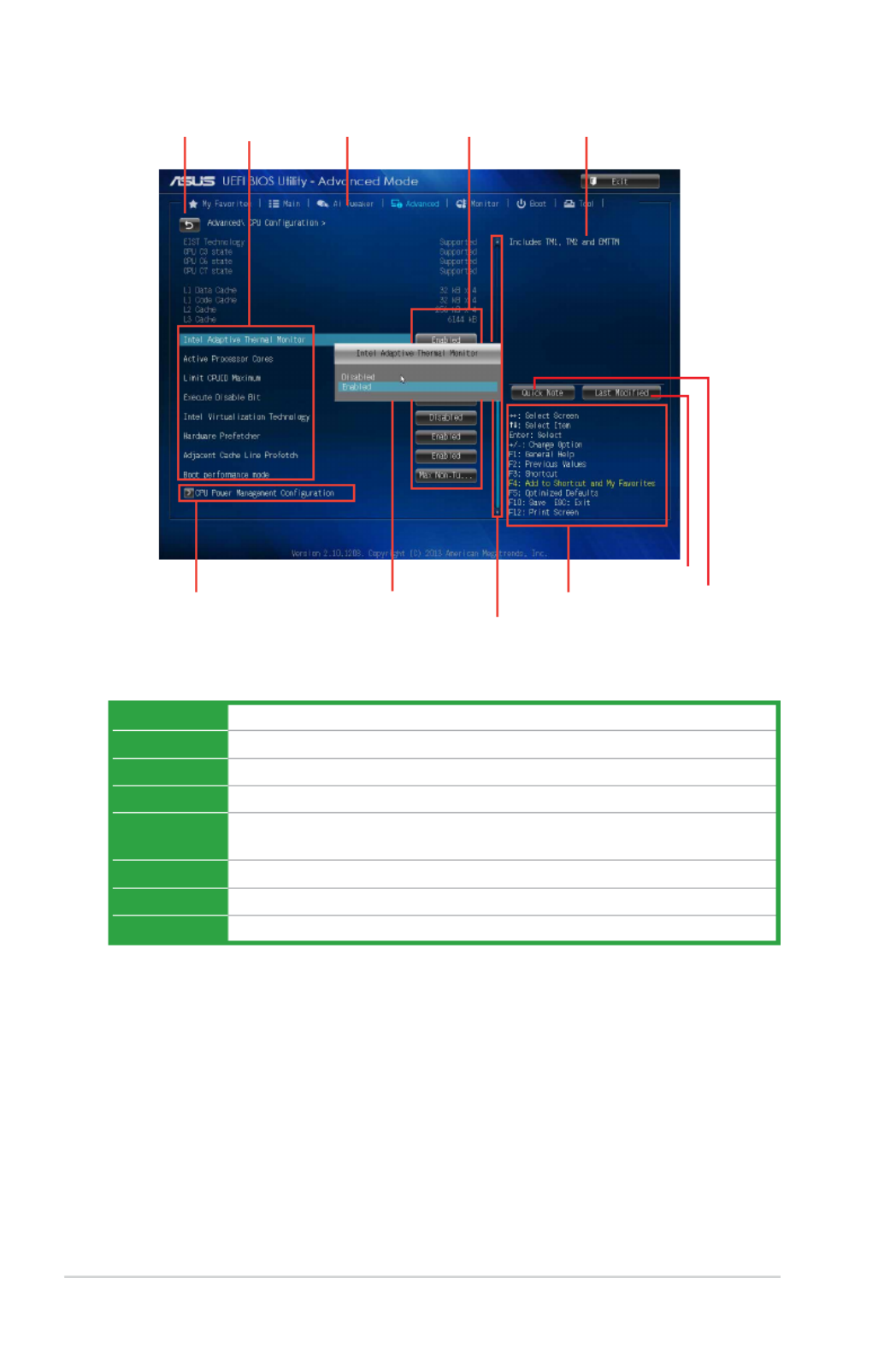
2.6.1 CPU Conguration
The items in this menu show the CPU-related information that the BIOS automatically detects.
The items shown in submenu may be different due to the CPU you installed.
Intel ®
Adaptive Thermal Monitor [Enabled]
[Enabled] Enables the overheated CPU to throttle its clock speed to cool down.
[Disabled] Disables the CPU thermal monitor function.
Active Processor Cores [All]
Allows you to choose the number of CPU cores to activate in each processor package. Conguration
options: [All] [1] [2] [3]
Limit CPUID Maximum [Disabled]
[Enabled] Allows legacy operating systems to boot even without support for CPUs with
extended CPUID functions.
[Disabled] Disables this function.
Execute Disable Bit [Enabled]
[Enabled] EnablestheNo-ExecutionPageProtectionTechnology.
[Disabled] ForcestheXDfeatureagtoalwaysreturntozero(0).

ASUS H81M-C R2.0 2-23
Intel Virtualization Technology [Disabled]
[Enabled] Allows a hardware platform to run multiple operating systems separately and
simultaneously, enabling one system to virtually function as several systems.
[Disabled] Disables this function.
Hardware Prefetcher [Enabled]
[Enabled] Allows a hardware platform to automatically analyze the requirements and
prefetch data and codes for the CPU.
[Disabled] Disables this function.
Adjacent Cache Line Prefetch [Enabled]
[Enabled] Allowsahardwareplatformtoperformadjacentcachelineprefetching.
[Disabled] Disables this function.
Boot performance mode [Max Non-Tu...]
Thisitemallowsyoutoselectthebootperformancemode.Congurationoptions:[MaxNon-Turbo
Performance][Maxbattery][TurboPerformance]
CPU Power Management Conguration
This item allows you to manage and congure the CPU’s power.
EIST [Enabled]
Allows you to enable or disable the Enhanced Intel ®
SpeedStep Technology (EIST).
[Disabled] The CPU runs at its default speed.
[Enabled] The operating system controls the CPU speed.
Turbo Mode [Enabled]
Allows you to set the processor cores to run faster than the marked frequency in a specic
condition. Conguration options: [Enabled] [Disabled]
TurboModeisonlyavailableonselectedCPUmodelsonly.
CPU C states [Auto]
[Auto] Automatic conguration.
[Enabled] Enables the CPU C states.
[Disabled] Disables the CPU C states.
The following items appear only when you set the CPU C states to .[Enabled]
Enhanced C1 state [Enabled]
[Enabled] Enables enhanced C1 state.
[Disabled] Disables enhanced C1 state.
CPU C3 Report [Enabled]
Allows you to disable or enable the CPU C3 report to OS. Conguration options: [Enabled]
[Disabled]

2-24 Chapter 2: BIOS information
CPU C6 report [Enabled]
Allows you to disable or enable the CPU C6 report to OS. Conguration options: [Enabled]
[Disabled]
C6 Latency [Short]
Allows you to choose short or long latency for C6. Conguration options: [Short] [Long]
CPU C7 report [CPU C7s]
Allows you to disable or enable the CPU C7 report to OS. Conguration options: [Disabled]
[CPU C7] [CPU C7s]
C7 Latency [Long]
Allows you to choose short or long latency for C6. Conguration options: [Short] [Long]
Package C State Support [Auto]
Allows you to disable or enable the whole C-State package support. Conguration options:
[Auto][Enabled][C0/C1][C2][C3][C6][CPUC7][CPUC7s]
2.6.2 PCH Conguration
PCI Express Conguration
DMI Link ASPM Control [Auto]
AllowsyoutocontroltheActiveStatePowerManagemenntonbothNBandSBsideofthe
DMILink.Congurationoptions:[Auto][Enabled][Disabled]
ASPM Support [Disabled]
AllowsyoutosettheASPMsupport.Congurationoptions:[Disabled][Auto][L0s][L1]
L0sL1].
PCIe Speed [Auto]
Allows you to select the PCI Express port speed. Conguration options: [Auto] [Gen1] [Gen2]
Intel ®
Rapid Start Technology
Intel ®
Rapid Start Technology [Disabled]
Allows you to enable or disable Intel ®
Rapid Start Technology. Conguration options:
[Enabled] [Disabled]
The following items appear only when you set the Intel ®
Rapid Start Technology to .[Enabled]
Entry on S3 RTC Wake [Enabled]
The system automatically wakes up and set to Rapid Start Technology S4 mode.
Conguration options: [Enabled] [Disabled]
Entry After [x]
Allowsyoutosetthewake-uptime.Thevaluesrangefrom0(immediately)to120.
Active Page Threshold Support [Enabled]
The system automatically set itself to sleep when the partition size is not enough for Rapid
Start Technology to work. Conguration options: [Enabled] [Disabled]

ASUS H81M-C R2.0 2-25
Active Memory Threshold [0]
Key in the value for the additional partition size for Rapid Start Technology to work.
Ensure that the caching partition size is larger than the total memory size.
Hybrid Hard Disk Support [Disabled]
Allows you to enable or disable hybrid hard disk support.
Conguration options: [Enabled] [Disabled]
Intel ®
Smart Connect Technology [Disabled]
ISCT Support [Disabled]
Allows you to enable or disable the ISCT support. Conguration options: [Enabled] [Disabled]
2.6.3 SATA Conguration
While entering Setup, the BIOS automatically detects the presence of SATA devices. The SATA Port
itemsshowNotPresentifnoSATAdeviceisinstalledtothecorrespondingSATAport.
SATA Mode Selection [AHCI]
Allows you to set the SATA conguration.
[Disabled] Disables the SATA function.
[IDE] Set to [IDE] when you want to use the Serial ATA hard disk drives as Parallel ATA
physical storage devices.
[AHCI] Set to [AHCI] when you want the SATA hard disk drives to use the AHCI
(Advanced Host Controller Interface). The AHCI allows the onboard storage
driver to enable advanced Serial ATA features that increases storage
performance on random workloads by allowing the drive to internally optimize
the order of commands.
Aggressive LPM Support [Auto]
This item appears only when you set the previous item to [AHCI] and allows you to enable or
disable PCH entering link power state aggressively. Conguration options: [Auto] [Disabled]
[Enabled]
IDE Legacy / Native Mode Selection [Native]
ThisitemappearsonlywhenyousettheSATAModeSelectionitemto[IDE].Congurationoptions:
[Native][Legacy]
S.M.A.R.T. Status Check [Enabled]
S.M.A.R.T.(Self-Monitoring,AnalysisandReportingTechnology)isamonitorsystem.Whenread/
write of your hard disk errors occur, this feature allows the hard disk to report warning messages
during the POST. Conguration options: [Enabled] [Disabled]
Hot Plug [Disabled]
TheseitemsappearonlywhenyousettheSATAModeSelectionitemto[AHCI]andallowyouto
enable/disable SATA Hot Plug Support. Conguration options: [Disabled] [Enabled]

2-26 Chapter 2: BIOS information
2.6.4 System Agent Conguration
VT-d [Disabled]
AllowsyoutoenableordisableVT-dfunctiononMCH.Congurationoptions:[Enabled][Disabled]
CPU Audio Device [Disabled]
Allows you to enable or disable CPU SA Audio Device. Conguration options: [Enabled] [Disabled]
Graphics Conguration
Allows you to select a primary display from iGPU, and PCIe graphical devices.
Primary Display [Auto]
Allows you to select which of the iGPU/PCIE Graphics device should be the Primary Display.
Conguration options: [Auto] [iGPU] [PCIE] [PCI]
iGPU Memory [Auto]
AllowsyoutoselecttheamountofsystemmemoryallocatedtoDVMT5.0usedbythe
iGPU.Congurationoptions:[Auto][32M][64M][96M][128M][160M][192M][224M][256M]
[288M][320M][352M][384M][416M][448M][480M][512M][1024M]
Render Standby [Auto]
Allows you to enable or disable Intel ®
Graphics Render Standby support to reduce iGPU
power use when the system is idle. Conguration options: [Auto] [Disabled] [Enabled]
iGPU Multi-Monitor [Disabled]
Set this item to [Enabled] to empower both integrated and discrete graphics for multiple-
monitoroutput.TheiGPUsharedsystemmemorysizewillbexedat64MB.
Conguration options: [Disabled] [Enabled]
DMI Conguration
AllowsyoutocontrolvariousDMIfunctions.
DMI Gen 2 [Auto]
AllowsyoutoenableordisableDMIGen2.Congurationoptions:[Auto][Enabled]
[Disabled]
NB PCIe Conguration
AllowsyoutoconguretheNBPCIExpresssettings.
PCIEX16_1 Link Speed [Auto]
Allows you to congure the PCIEX16_1 speed. Conguration options: [Auto] [Gen1] [Gen2]
DMI Link ASPM Control [Auto]
AllowsyoutoenableordisablethecontrolofActiveStatePowerManagementonSAsideof
theDMILink.Congurationoptions:[Auto][Disabled][L0s][L1][L0sL1]
PEG - ASPM [Disabled]
AllowsyoutocontrolASPMsupportforthePEGDevice.ThesettingtakesnoeectifPEGis
nottheactivedeviceatpresent.Congurationoptions:[Disabled][Auto][ASPML0s][ASPM
L1][ASPML0sL1]

ASUS H81M-C R2.0 2-27
Memory Conguration
Memory Scrambler [Enabled]
AllowsyoutoenableordisableMemoryScramblersupport.
Memory Remap [Enabled]
Allows you to enable or disable remapping the memory above 4GB.
[Enabled] Enables the function.
[Disabled] Disables this function.
2.6.5 USB Conguration
The items in this menu allow you to change the USB-related features.
The item shows the auto-detected values. If no USB device is detected, the item USB Devices
showsNone.
Legacy USB Support [Enabled]
[Disabled] The USB devices can be used only for the BIOS setup program.
[Enabled] Enables the support for USB devices on legacy operating systems (OS).
[Auto] Allows the system to detect the presence of USB devices at startup. If detected,
the USB controller legacy mode is enabled. If no USB device is detected, the
legacy USB support is disabled.
Intel xHCI Mode [Smart Auto]
[Smart Auto] Enables the operation of xHCI controller.
[Auto] Keeps the last operation of xHCI controller in OS during bootup.
[Enabled] Enables the function.
[Disabled] Disables the function.
EHCI Hand-off [Disabled]
[Enabled] Enables the support for operating systems without an EHCI hand-off feature.
[Disabled] Disables the function.
USB Single Port Control
USB3_1~2 [Enabled]
Allows you to enable or disable an individual USB port. Refer to the section 1.2.3
Motherboard layout in this user guide for the locations of the USB ports. Conguration
options: [Enabled] [Disabled].
USB_3~6, 9~12 [Enabled]
Allows you to enable or disable an individual USB port. Refer to the section 1.2.3
Motherboard layout in this user guide for the locations of the USB ports. Conguration
options: [Enabled] [Disabled].

2-28 Chapter 2: BIOS information
2.6.6 Platform Misc Conguration
TheitemsinthismenuallowyoutocongurethePlatformMisc.
PCI Express Native Power Management [Disabled]
AllowsyoutoenhancethepowersavingfeatureofPCIExpressandperformASPMoperationsinthe
operating system. Conguration options: [Disabled] [Enabled]
Native ASPM [Disabled]
The item appears only when you set the previous item to [Enabled] and allows you to enable or
disableASPM.Congurationoptions:[Enabled][Disabled]
2.6.7 Onboard Devices Conguration
HD Audio Controller [Enabled]
[Enabled] Enables the HD Audio Device.
[Disabled] Disables the HD Audio Device.
The following two items appear only when you set the HD Audio Controller item to [Enabled].
Front Panel Type [HD]
Allows you to set the front panel audio connector (AAFP) mode to legacy AC’97 or high-denition
audio depending on the audio standard that the front panel audio module supports.
[HD] Sets the front panel audio connector (AAFP) mode to high denition audio.
[AC97] Sets the front panel audio connector (AAFP) mode to legacy AC’97
Realtek LAN Controller [Enabled]
[Enabled] EnablestheRealtekLANcontroller.
[Disabled] Disables the controller.
Realtek PXE Option Rom [Disabled]
This item appears only when you set the previous item to [Enabled] and allows you to enable
ordisablethePXEOptionRomoftheRealtekLANcontroller.Congurationoptions:[Enabled]
[Disabled]
Serial Port Conguration
The sub-items in this menu allow you to set the serial port conguration.
Serial Port [Enabled]
Allowsyoutoenableordisabletheserialport(COM).Congurationoptions:[Enabled]
[Disabled]
Change Settings [IO=3F8h; IRQ=4]
This item appears only when you set the Serial Port to [Enabled] and allows you to select
theSerialPortbaseaddress.Congurationoptions:[IO=3F8h;IRQ=4][IO=2F8h;IRQ=3]
[IO=3E8h;IRQ=4][IO=2E8h;IRQ=3]
Parallel Port Conguration
The sub-items in this menu allow you to set the parallel port conguration.

ASUS H81M-C R2.0 2-29
Parallel Port [Enabled]
Allows you to enable or disable the parallel port (LPT/LPTE).
Conguration options: [Enabled] [Disabled]
The following items appear only when you set the Parallel Port Conguration item to [Enabled].
Change Settings [Auto]
Allows you to select an optimal setting for Super I/O devices. Conguration options:
[Auto][IO=378h;IRQ=5;][IO=378h;IRQ=5,6,7,9,10,11,12;][IO=278h;IRQ=5,6,7,9,10,11,12;]
[IO=3BCh;IRQ=5,6,7,9,10,11,12;]
Device Mode [STD Printe...]
AllowsyoutoselectthePrinterPortmode.Congurationoptions:[STDPrinterMode][SPP
Mode][EPP-1.9andSPPMode][EPP-1.7andSPPMode][ECPMode][ECPandEPP1.9Mode]
[ECPandEPP1.7Mode]
2.6.8 APM
Restore AC Power Loss [Power Off]
[Power On] The system goes into on state after an AC power loss.
[Power Off] The system goes into off state after an AC power loss.
[Last State] The system goes into either off or on state, whatever the system state was before
the AC power loss.
Power On By PCIE/PCI [Disabled]
[Disabled] DisablesthePCIE/PCIdevicestogenerateawake-on-LANfeatureoftheIntel
®
/
RealtekLANdevice.
[Enabled] EnablesthePCIE/PCIdevicestogenerateawake-on-LANfeatureoftheIntel
®
/
RealtekLANdevice.
Power On By Ring [Disabled]
[Disabled] Disables Ring to generate a wake event.
[Enabled] Enables Ring to generate a wake event.
Power On By RTC [Disabled]
[Disabled] Disables RTC to generate a wake event.
[Enabled] When set to [Enabled], the items RTC Alarm Date (Days) Hour/Minute/ and
Second will become user-congurable with set values.

2-30 Chapter 2: BIOS information
2.6.9 Network Stack Conguration
Network Stack [Disabled]
This item allows user to disable or enable the UEFI network stack. Conguration options: [Disabled]
[Enabled]
The following two items appear only when you set the previous item to [Enabled].
Ipv4 PXE Support [Enabled]
This item allows user to disable or enable the Ipv4 PXE Boot support. Conguration options:
[Disabled] [Enabled]
Ipv6 PXE Support [Enabled]
This item allows user to disable or enable the Ipv6 PXE Boot support. Conguration options:
[Disabled] [Enabled]
2.7 Monitor menu
TheMonitormenudisplaysthesystemtemperature/powerstatus,andallowsyoutochangethe
fan settings.
Scroll down to display the other items.

ASUS H81M-C R2.0 2-31
2.7.1 CPU Temperature [xxxºC/xxxºF]
The onboard hardware monitor automatically detects and displays the CPU temperature. Select
Ignore if you do not wish to display the detected temperature.
2.7.2 CPU / Chassis Fan Speed [xxxx RPM] or [Ignore] / [N/A]
The onboard hardware monitor automatically detects and displays the CPU / chassis fan speeds in
rotationsperminute(RPM).Ifthefanisnotconnectedtothemotherboard,theeldshowsN/A.
Select Ignore if you do not wish to display the detected speed.
2.7.3 CPU Input Voltage (VCCIN), 3.3V Voltage, 5V Voltage, 12V
Voltage
The onboard hardware monitor automatically detects the voltage output through the onboard
voltage regulators. Select Ignore if you do not want to detect this item.
2.7.4 CPU Q-Fan Control [Enabled]
[Disabled] DisablestheCPUQ-Fancontrolfeature.
[Enabled] EnablestheCPUQ-Fancontrolfeature.
CPU Fan Speed Low Limit [200 RPM]
ThisitemappearsonlywhenyouenabletheCPUQ-FanControlfeatureandallowsyoutodisableor
set the CPU fan warning speed.
Congurationoptions:[Ignore][100RPM][200RPM][300RPM][400RPM][500RPM]
CPU Fan Prole [Standard]
ThisitemappearsonlywhenyouenabletheCPUQ-FanControlfeatureandallowsyoutosetthe
appropriate performance level of the CPU fan.
[Standard] Setsto[Standard]tomaketheCPUfanautomaticallyadjustdependingonthe
CPU temperature.
[Silent] Sets to [Silent] to minimize the fan speed for quiet CPU fan operation.
[Turbo] Sets to [Turbo] to achieve maximum CPU fan speed.
[Manual] Setsto[Manual]toassigndetailedfanspeedcontrolparameters.
ThefollowingfouritemsappearonlywhenyousetCPUFanProleto[Manual].
CPU Upper Temperature [70]
Usethe<+>and<->keystoadjusttheupperlimitoftheCPUtemperature.Thevaluesrange
from20ºCto75ºC.
CPU Fan Max. Duty Cycle(%) [100]
Usethe<+>and<->keystoadjustthemaximumCPUfandutycycle.Thevaluesrangefrom
20%to100%.WhentheCPUtemperaturereachestheupperlimit,theCPUfanwilloperateat
the maximum duty cycle.

2-32 Chapter 2: BIOS information
CPU Lower Temperature [20]
Displays the lower limit of the CPU temperature.
CPU Fan Min. Duty Cycle(%) [20]
Usethe<+>and<->keystoadjusttheminimumCPUfandutycycle.Thevaluesrangefrom
20%to100%.WhentheCPUtemperatureisunderthelowerlimit,theCPUfanwilloperateat
the minimum duty cycle.
2.7.5 Chassis Q-Fan Control [Enabled]
[Disabled] DisablestheChassisQ-Fancontrolfeature.
[Enabled] EnablestheChassisQ-Fancontrolfeature.
Chassis Fan Speed Low Limit [600 RPM]
ThisitemappearsonlywhenyouenabletheChassisQ-FanControlfeatureandallowsyouto
disable or set the chassis fan warning speed.
Congurationoptions:[Ignore][200RPM][300RPM][400RPM][500RPM][600RPM]
Chassis Fan Prole [Standard]
ThisitemappearsonlywhenyouenabletheChassisQ-FanControlfeatureandallowsyoutosetthe
appropriate performance level of the chassis fan.
[Standard] Setsto[Standard]tomakethechassisfanautomaticallyadjustdependingon
the chassis temperature.
[Silent] Sets to [Silent] to minimize the fan speed for quiet chassis fan operation.
[Turbo] Sets to [Turbo] to achieve maximum chassis fan speed.
[Manual] Setsto[Manual]toassigndetailedfanspeedcontrolparameters.
ThefollowingfouritemsappearonlywhenyousetChassisFanProleto[Manual].
Chassis Upper Temperature [70]
Usethe<+>and<->keystoadjusttheupperlimitofthechassistemperature.Thevalues
rangefrom40ºCto75ºC.
Chassis Fan Max. Duty Cycle(%) [100]
Usethe<+>and<->keystoadjustthemaximumchassisfandutycycle.Thevaluesrange
from60%to100%.Whenthechassistemperaturereachestheupperlimit,thechassisfan
will operate at the maximum duty cycle.
Chassis Lower Temperature [40]
Displays the lower limit of the chassis temperature.
Chassis Fan Min. Duty Cycle(%) [60]
Usethe<+>and<->keystoadjusttheminimumchassisfandutycycle.Thevaluesrange
from60%to100%.Whenthechassistemperatureisunder40ºC,thechassisfanwilloperate
at the minimum duty cycle.
2.7.6 Anti Surge Support [Disabled]
This item allows you to enable or disable the Anti Surge function.
Conguration options: [Disabled] [Enabled]

ASUS H81M-C R2.0 2-33
2.8 Boot menu
The Boot menu items allow you to change the system boot options.
Scroll down to display the other items.
2.8.1 Fast Boot [Enabled]
[Enabled] Select to accelerate the boot speed.
[Disabled] Select to go back to normal boot.
The following ve items appear when you set Fast Boot to [Enabled].
SATA Support [All Devices]
[All Devices] All devices connected to SATA ports will be available during POST.
This process will extend the POST time.
[Hard Drive Only] Only hard drives connected to SATA ports will be detected during
POST. Any hardware change will disable fast boot.
[Boot Drive Only] Only boot drive connected to SATA ports will be detected during
POST. Any hardware change will disable fast boot.
USB Support [Partial In...]
[Disabled] All USB devices will not be available until OS boot up for a fastest
POST time.
[Full Initialization] All USB devices will be available during POST. This process will extend
the POST time.
[Partial Initialization] For a faster POST time, only the USB ports with keyboard and mouse
connections will be detected.

2-34 Chapter 2: BIOS information
PS/2 Keyboard and Mouse Support [Auto]
Select any of these settings when PS/2 keyboard and mouse are installed. These settings only apply
when Fast Boot is enabled.
[Auto] For a faster POST time, PS/2 devices will only be available when the system
boots up or rebooted when the PS/2 devices have not been reconnected or
changed. If you disconnect or change PS/2 devices before restarting the system,
PS/2 devices will not be available and BIOS setup program will not be accessible
via PS/2 devices.
[Full Initialization] For full system control, PS/2 devices will be available during POST at any
circumstances. This process will extend POST time.
[Disabled] For the fastest POST time, all PS/2 devices will not be available until your
computer enters the operating system.
Network Stack Driver Support [Disabled]
[Disabled] Select to skip the network stack driver from loading during POST.
[Enabled] Select to load the network stack driver during POST.
Next Boot after AC Power Loss [Normal Boot]
[NormalBoot] ReturnstonormalbootonthenextbootafterACpowerloss.
[Fast Boot] Accelerates the boot speed on the next boot after AC power loss.
2.8.2 Boot Logo Display [Auto]
[Auto] AdjustautomaticallyforWindows®requrement.
[FullScreen] Maximizethebootlogosize.
[Disabled] Hide the logo during POST.
POST Delay Time [3 sec]
This item appears only when you set Boot Logo Display to [Auto] or [Full Screen]. This item allows
you to select the desired additional POST waiting time to easily enter the BIOS setup. You can only
executethePOSTdelaytimeduringNormalBoot.Thevaluesrangefrom0to10seconds.
This feature will only work under normal boot.
Post Report [5 sec]
This item appears only when you set Boot Logo Display to [Disabled]. This item allows you to
selectadesiredpostreportwaitingtime.Congurationoptions:[1sec]~[10sec][UntilPressESC].
2.8.3 Bootup NumLock State [On]
[On] Setsthepower-onstateoftheNumLockto[On].
[O] Setsthepower-onstateoftheNumLockto[O].
2.8.4 Wait for ‘F1’ If Error [Enabled]
When this item is set to [Enabled], the system waits for the F1 key to be pressed when error occurs.
Conguration options: [Disabled] [Enabled]

ASUS H81M-C R2.0 2-35
2.8.5 Option ROM Messages [Force BIOS]
[ForceBIOS] Thethird-partyROMmessageswillbeforcedtodisplayduringtheboot
sequence.
[KeepCurrent] Thethird-partyROMmessageswillbedisplayedonlyifthethird-party
manufacturer had set the add-on device to do so.
2.8.6 Interrupt 19 Capture [Disabled]
[Enabled] AllowstheoptionROMstotrapInterrupt19.
[Disabled] Disables this function.
2.8.7 Setup Mode [EZ Mode]
[AdvancedMode] SetsAdvancedModeasthedefaultscreenforenteringtheBIOSsetupprogram.
[EZMode] SetsEZModeasthedefaultscreenforenteringtheBIOSsetupprogram.
2.8.8 CSM (Compatibility Support Module)
AllowsyoutoconguretheCSM(CompatibilitySupportModule)itemstofullysupportthevarious
VGA, bootable devices and add-on devices for better compatibility.
Launch CSM [Enabled]
[Auto] The system automatically detects the bootable devices and the add-on devices.
[Enabled] Forbettercompatibility,enabletheCSMtofullysupportthenon-UEFIdriver
add-on devices or the Windows ®
UEFI mode.
[Disabled] DisabletheCSMtofullysupporttheWindows
®
Security Update and Security
Boot.
ThefollowingfouritemsappearwhenyousetLaunchCSMto[Enabled].
Boot Device Control [UEFI and L...]
Allows you to select the type of devices that you want to boot up. Conguration options: [UEFI and
LegacyOPROM][LegacyOPROMonly][UEFIonly]
Boot from Network Devices [Legacy OPR...]
Allows you to select the type of network devices that you want to launch. Conguration options:
[LegacyOPROMrst][UEFIdriverrst][Ignore]

2-36 Chapter 2: BIOS information
Boot from Storage Devices [Legacy OPR...]
Allows you to select the type of storage devices that you want to launch. Conguration options:
[Both,LegacyOPROMrst][Both,UEFIrst][LegacyOPROMrst][UEFIdriverrst][Ignore]
Boot from PCI-E/PCI Expansion Devices [Legacy OPR...]
Allows you to select the type of PCIe/PCI expansion devices that you want to launch. Conguration
options:[LegacyOPROMrst][UEFIdriverrst]
2.8.9 Secure Boot
Allows you to congure the Windows ®
Secure Boot settings and manage its keys to protect the
system from unauthorized access and malwares during POST.
OS Type [Windows UE...]
Allows you to select your installed operating system.
[WindowsUEFImode] ExecutestheMicrosoft
®
Secure Boot check. Only select this option
when booting on Windows ®
UEFImodeorotherMicrosoft
®
Secure
Boot compliant OS.
[Other OS] Get the optimized function when booting on Windows ®
non-UEFI
mode, Windows ®
Vista/XP,orotherMicrosoft
®
Secure Boot non-
compliant OS. Only on Windows®
UEFImodethatMicrosoft
®
Secure
Boot can function properly.
The following item appears when OS Type is set to [Windows UEFI mode].
Key Management
ThisitemappearsonlywhenyousetOSTypeto[WindowsUEFIMode].Itallowsyouto
manage the Secure Boot keys.
Install Default Secure Boot keys
Allows you to immediately load the default Security Boot keys, Platform key (PK),
Key-exchange Key (KEK), Signature database (db), and Revoked Signatures (dbx).
When the default Secure boot keys are loaded, the PK state will change from
Unloaded mode to loaded mode.
Clear Secure Boot keys
This item appears only when you load the default Secure Boot keys. This item
allows you to clear all default Secure Boot keys.
Save Secure Boot Keys
Allows you to save the PK (Platform Keys) to a USB storage device.
PK Management
The Platform Key (PK) locks and secures the rmware from any non-permissible changes. The
system veries the PK before your system enters the OS.
Delete PK
Allows you to delete the PK from your system. Once the PK is deleted, all the
system’sSecureBootkeyswillnotbeactive.Congurationoptions:[Yes][No]
Load PK from File
Allows you to load the downloaded PK from a USB storage device.
The PK le must be formatted as a UEFI variable structure with time-based authenticated variable.

ASUS H81M-C R2.0 2-37
KEK Management
The KEK (Key-exchange Key or Key Enrollment Key) manages the Signature database (db)
and Revoked Signature database (dbx).
Key-exchangeKey(KEK)referstoMicrosoft
®
Secure Boot Key-Enrollment Key (KEK).
Delete the KEK
AllowsyoutodeletetheKEKfromyoursystem.Congurationoptions:[Yes][No]
Load KEK from File
Allows you to load the downloaded KEK from a USB storage device.
Append KEK from le
Allows you to load the additional KEK from a storage device for an additional db
and dbx loaded management.
The KEK le must be formatted as a UEFI variable structure with time-based authenticated
variable.
DB Management
The db (Authorized Signature database) lists the signers or images of UEFI applications,
operating system loaders, and UEFI drivers that you can load on the single computer.
Delete the db
Allows you to delete the db le from your system. Conguration options: [Yes]
[No]
Load db from File
Allows you to load the downloaded db from a USB storage device.
Append db from le
Allows you to load the additional db from a storage device so that more images
can be loaded securely.
The DB le must be formatted as a UEFI variable structure with time-based authenticated
variable.
DBX Management
The dbx (Revoked Signature database) lists the forbidden images of db items that are no
longer trusted and cannot be loaded.
Delete the DBX
Allows you to delete the DBX le from your system. Conguration options: [Yes]
[No]
Load DBX from File
Allows you to load the downloaded DBX from a USB storage device.
Append DBX from le
Allows you to load the additional DBX from a storage device so that more db’s
images cannot be loaded.
The DBX le must be formatted as a UEFI variable structure with time-based authenticated
variable.
Produktspecifikationer
| Varumärke: | Asus |
| Kategori: | moderkort |
| Modell: | H81M-C R2.0 |
Behöver du hjälp?
Om du behöver hjälp med Asus H81M-C R2.0 ställ en fråga nedan och andra användare kommer att svara dig
moderkort Asus Manualer

8 April 2025
8 April 2025
3 April 2025
3 April 2025
3 April 2025
3 April 2025
2 April 2025
2 April 2025
1 April 2025
27 Mars 2025
moderkort Manualer
- moderkort Sharkoon
- moderkort Gigabyte
- moderkort Asrock
- moderkort Supermicro
- moderkort Evga
- moderkort Intel
- moderkort MSI
- moderkort ECS
- moderkort NZXT
- moderkort Foxconn
- moderkort Advantech
- moderkort Elitegroup
- moderkort EPoX
- moderkort Biostar
Nyaste moderkort Manualer
30 Mars 2025
25 Mars 2025
10 Mars 2025
3 Mars 2025
3 Mars 2025
3 Mars 2025
3 Mars 2025
3 Mars 2025
3 Mars 2025