Asus P5N64 WS Professional Bruksanvisning
Läs nedan 📖 manual på svenska för Asus P5N64 WS Professional (188 sidor) i kategorin Server. Denna guide var användbar för 10 personer och betygsatt med 4.5 stjärnor i genomsnitt av 2 användare
Sida 1/188

Motherboard
P5N64 WS
Professional

ii
E3685
First Edition
March 2008
Copyright © 2008 ASUSTeK COMPUTER INC. All Rights Reserved.
No part of this manual, including the products and software described in it, may be reproduced,
transmitted, transcribed, stored in a retrieval system, or translated into any language in any form or by any
means, except documentation kept by the purchaser for backup purposes, without the express written
permission of ASUSTeK COMPUTER INC. (“ASUS”).
Product warranty or service will not be extended if: (1) the product is repaired, modied or altered, unless
such repair, modication of alteration is authorized in writing by ASUS; or (2) the serial number of the
product is defaced or missing.
ASUS PROVIDES THIS MANUAL “AS IS” WITHOUT WARRANTY OF ANY KIND, EITHER EXPRESS
OR IMPLIED, INCLUDING BUT NOT LIMITED TO THE IMPLIED WARRANTIES OR CONDITIONS OF
MERCHANTABILITY OR FITNESS FOR A PARTICULAR PURPOSE. IN NO EVENT SHALL ASUS, ITS
DIRECTORS, OFFICERS, EMPLOYEES OR AGENTS BE LIABLE FOR ANY INDIRECT, SPECIAL,
INCIDENTAL, OR CONSEQUENTIAL DAMAGES (INCLUDING DAMAGES FOR LOSS OF PROFITS,
LOSS OF BUSINESS, LOSS OF USE OR DATA, INTERRUPTION OF BUSINESS AND THE LIKE),
EVEN IF ASUS HAS BEEN ADVISED OF THE POSSIBILITY OF SUCH DAMAGES ARISING FROM ANY
DEFECT OR ERROR IN THIS MANUAL OR PRODUCT.
SPECIFICATIONS AND INFORMATION CONTAINED IN THIS MANUAL ARE FURNISHED FOR
INFORMATIONAL USE ONLY, AND ARE SUBJECT TO CHANGE AT ANY TIME WITHOUT NOTICE,
AND SHOULD NOT BE CONSTRUED AS A COMMITMENT BY ASUS. ASUS ASSUMES NO
RESPONSIBILITY OR LIABILITY FOR ANY ERRORS OR INACCURACIES THAT MAY APPEAR IN THIS
MANUAL, INCLUDING THE PRODUCTS AND SOFTWARE DESCRIBED IN IT.
Products and corporate names appearing in this manual may or may not be registered trademarks or
copyrights of their respective companies, and are used only for identication or explanation and to the
owners’ benet, without intent to infringe.

iii
Contents
Contents ...................................................................................................... iii
Notices ....................................................................................................... viii
Safety information ...................................................................................... ix
About this guide .......................................................................................... x
P5N64 WS Professional specications .................................................. xii
Chapter 1: Product introduction
1.1 Welcome! ...................................................................................... 1-1
1.2 Package contents ......................................................................... 1-1
1.3 Special features ............................................................................ 1-2
1.3.1 Product highlights ........................................................... 1-2
1.3.2 ASUS special features ................................................... 1-5
1.3.3 ASUS Intelligent Overclocking features .......................... 1-8
Chapter 2: Hardware information
2.1 Before you proceed ..................................................................... 2-1
2.2 Motherboard overview ................................................................. 2-2
2.2.1 Placement direction ........................................................ 2-2
2.2.2 Screw holes .................................................................... 2-2
2.2.3 Motherboard layout ......................................................... 2-3
2.2.4 Layout contents ............................................................... 2-4
2.3 Central Processing Unit (CPU) ................................................... 2-6
2.3.1 Installing the CPU ........................................................... 2-7
2.3.2 Installing the CPU heatsink and fan ................................ 2-9
2.3.3 Uninstalling the CPU heatsink and fan ..........................2-11
2.4 System memory ......................................................................... 2-13
2.4.1 Overview ....................................................................... 2-13
2.4.2 Memory congurations .................................................. 2-14
2.4.3 Installing a DIMM .......................................................... 2-15
2.4.4 Removing a DIMM ........................................................ 2-15
2.5 Expansion slots .......................................................................... 2-16
2.5.1 Installing an expansion card ......................................... 2-16
2.5.2 Conguring an expansion card ..................................... 2-16
2.5.3 Interrupt assignments ................................................... 2-17
2.5.4 PCI slots ........................................................................ 2-18
2.5.5 PCI Express p3-x1 slot ....................................................... 2-18

iv
Contents
2.5.6 PCI Express 2.0 x16 slots (blue) ................................... 2-18
2.5.7 Universal PCI Express x16 slots (black and white) ....... 2-18
2.6 Jumper ........................................................................................ 2-20
2.7 Connectors ................................................................................. 2-21
2.7.1 Rear panel connectors .................................................. 2-21
2.7.2 Internal connectors ....................................................... 2-24
2.8 G.P. Diagnosis card installation ................................................ 2-35
2.8.1 G.P. Diagnosis card layout ............................................ 2-35
2.8.2 Installing G.P. Diagnosis card ....................................... 2-35
2.8.3 G.P. Diagnosis card check codes.................................. 2-36
Chapter 3: Powering up
3.1 Starting up for the rst time ........................................................ 3-1
3.2 Turning off the computer ............................................................. 3-2
3.2.1 Using the OS shut down function .................................... 3-2
3.2.2 Using the dual function power switch .............................. 3-2
Chapter 4: BIOS setup
4.1 Managing and updating your BIOS ............................................ 4-1
4.1.1 ASUS Update utility ........................................................ 4-1
4.1.2 Creating a bootable oppy disk ....................................... 4-4
4.1.3 ASUS EZ Flash 2 utility ................................................... 4-5
4.1.4 AFUDOS utility ................................................................ 4-6
4.1.5 ASUS CrashFree BIOS 3 utility ...................................... 4-8
4.2 BIOS setup program .................................................................... 4-9
4.2.1 BIOS menu screen ........................................................ 4-10
4.2.2 Menu bar ....................................................................... 4-10
4.2.3 Navigation keys ............................................................. 4-10
4.2.4 Menu items ....................................................................4-11
4.2.5 Sub-menu items .............................................................4-11
4.2.6 Conguration elds ........................................................4-11
4.2.7 Pop-up window ..............................................................4-11
4.2.8 Scroll bar ........................................................................4-11
4.2.9 General help ..................................................................4-11
4.3 Main menu .................................................................................. 4-12
4.3.1 System Time ................................................................. 4-12

v
Contents
4.3.2 System Date ................................................................. 4-12
4.3.3 Legacy Diskette A ......................................................... 4-12
4.3.4 Language ...................................................................... 4-12
4.3.5 Primary IDE Master/Slave ............................................. 4-13
4.3.6 SATA 1~6 ...................................................................... 4-14
4.3.7 IDE Conguration .......................................................... 4-15
4.3.8 System Information ....................................................... 4-16
4.4 Ai Tweaker menu ........................................................................ 4-17
4.5 Advanced menu ......................................................................... 4-21
4.5.1 USB Conguration ........................................................ 4-21
4.5.2 CPU Conguration ........................................................ 4-22
4.5.3 Chipset .......................................................................... 4-23
4.5.4 Onboard Devices Conguration .................................... 4-24
4.5.5 PCI PnP ........................................................................ 4-25
4.6 Power menu ................................................................................ 4-26
4.6.1 Suspend Mode .............................................................. 4-26
4.6.2 Repost Video on S3 Resume ........................................ 4-26
4.6.3 ACPI 2.0 Support .......................................................... 4-26
4.6.4 ACPI APIC Support ....................................................... 4-26
4.6.5 APM Conguration ........................................................ 4-27
4.6.6 Hardware Monitor ......................................................... 4-28
4.7 Boot menu .................................................................................. 4-30
4.7.1 Boot Device Priority ...................................................... 4-30
4.7.2 Boot Settings Conguration .......................................... 4-31
4.7.3 Security ......................................................................... 4-32
4.8 Tools menu ................................................................................. 4-34
4.8.1 ASUS EZ Flash 2 .......................................................... 4-34
4.8.2 Express Gate ................................................................ 4-35
4.8.3 ASUS O.C. Prole ......................................................... 4-35
4.8.4 Ai Net 2 ......................................................................... 4-37
4.9 Exit menu .................................................................................... 4-38
Chapter 5: Software support
5.1 Installing an operating system ................................................... 5-1
5.2 Support DVD information ............................................................ 5-1
5.2.1 Running the support DVD ............................................... 5-1

vi
Contents
5.2.2 Drivers menu ................................................................... 5-2
5.2.3 Utilities menu .................................................................. 5-3
5.2.4 Make Disk menu ............................................................. 5-5
5.2.5 Manual menu .................................................................. 5-6
5.2.6 ASUS Contact information .............................................. 5-6
5.2.7 Other information ............................................................ 5-7
5.3 Software information ................................................................... 5-9
5.3.1 ASUS MyLogo2™ ........................................................... 5-9
5.3.2 ASUS PC Probe II ..........................................................5-11
5.3.3 ASUS AI Suite ............................................................... 5-17
5.3.4 ASUS EPU Utility -- AI Gear 3+ ..................................... 5-19
5.3.5 ASUS AI Nap ................................................................ 5-21
5.3.6 ASUS Q-Fan 2 .............................................................. 5-22
5.3.7 ASUS AI Booster ........................................................... 5-23
5.3.8 AI Audio 2 (SoundMAX® High Denition Audio utility) ... 5-24
5.3.9 ASUS Express Gate ..................................................... 5-33
5.4 RAID congurations .................................................................. 5-40
5.4.1 RAID denitions ............................................................ 5-40
5.4.2 NVIDIA® RAID congurations........................................ 5-41
5.4.3 Marvell® eSATA RAID congurations ............................ 5-48
5.4.4 Marvell® SAS RAID congurations ................................ 5-54
5.5 Creating a RAID driver disk ....................................................... 5-63
5.5.1 Creating a RAID driver disk without entering the OS .... 5-63
5.5.2 Creating a SATA RAID driver disk in Windows® ............ 5-63
Chapter 6: NVIDIA ® SLI™ technology support
6.1 Overview ....................................................................................... 6-1
Requirements ................................................................................. 6-1
6.2 Graphics card setup .................................................................... 6-2
6.2.1 Installing three SLI-ready graphics cards ........................ 6-2
6.2.2 Installing two SLI-ready graphics cards .......................... 6-5
6.2.3 Installing the device drivers ............................................. 6-6
6.2.4 Enabling the NVIDIA® SLI™ technology in Windows® .... 6-6
Appendix: CPU features
A.1 Intel ® EM64T ..................................................................................A-1

vii
Contents
Using the Intel® EM64T feature ......................................................A-1
A.2 Enhanced Intel SpeedStep® Technology (EIST) ........................A-1
A.2.1 System requirements ......................................................A-1
A.2.2 Using the EIST ................................................................A-2
A.3 Intel® Hyper-Threading Technology ...........................................A-3
Using the Hyper-Threading Technology ........................................A-3

viii
Notices
Federal Communications Commission Statement
This device complies with Part 15 of the FCC Rules. Operation is subject to the
following two conditions:
•
This device may not cause harmful interference, and
•
This device must accept any interference received including interference that
may cause undesired operation.
This equipment has been tested and found to comply with the limits for a
Class B digital device, pursuant to Part 15 of the FCC Rules. These limits are
designed to provide reasonable protection against harmful interference in a
residential installation. This equipment generates, uses and can radiate radio
frequency energy and, if not installed and used in accordance with manufacturer’s
instructions, may cause harmful interference to radio communications. However,
there is no guarantee that interference will not occur in a particular installation. If
this equipment does cause harmful interference to radio or television reception,
which can be determined by turning the equipment off and on, the user is
encouraged to try to correct the interference by one or more of the following
measures:
•
Reorient or relocate the receiving antenna.
•
Increase the separation between the equipment and receiver.
•
Connect the equipment to an outlet on a circuit different from that to which the
receiver is connected.
•
Consult the dealer or an experienced radio/TV technician for help.
Canadian Department of Communications Statement
This digital apparatus does not exceed the Class B limits for radio noise emissions
from digital apparatus set out in the Radio Interference Regulations of the
Canadian Department of Communications.
This class B digital apparatus complies with Canadian ICES-003.
The use of shielded cables for connection of the monitor to the graphics card is
required to assure compliance with FCC regulations. Changes or modications
to this unit not expressly approved by the party responsible for compliance
could void the user’s authority to operate this equipment.

ix
Safety information
Electrical safety
•
To prevent electrical shock hazard, disconnect the power cable from the
electrical outlet before relocating the system.
•
When adding or removing devices to or from the system, ensure that the
power cables for the devices are unplugged before the signal cables are
connected. If possible, disconnect all power cables from the existing system
before you add a device.
•
Before connecting or removing signal cables from the motherboard, ensure
that all power cables are unplugged.
•
Seek professional assistance before using an adpater or extension cord.
These devices could interrupt the grounding circuit.
•
Make sure that your power supply is set to the correct voltage in your area.
If you are not sure about the voltage of the electrical outlet you are using,
contact your local power company.
•
If the power supply is broken, do not try to x it by yourself. Contact a
qualied service technician or your retailer.
Operation safety
•
Before installing the motherboard and adding devices on it, carefully read all
the manuals that came with the package.
•
Before using the product, make sure all cables are correctly connected and the
power cables are not damaged. If you detect any damage, contact your dealer
immediately.
•
To avoid short circuits, keep paper clips, screws, and staples away from
connectors, slots, sockets and circuitry.
•
Avoid dust, humidity, and temperature extremes. Do not place the product in
any area where it may become wet.
•
Place the product on a stable surface.
•
If you encounter technical problems with the product, contact a qualied
service technician or your retailer.
This symbol of the crossed out wheeled bin indicates that the product (electrical,
electronic equipment and mercury-containing button cell battery) should not
be placed in municipal waste. Check local regulations for disposal of electronic
products.

x
About this guide
This user guide contains the information you need when installing and conguring
the motherboard.
How this guide is organized
This guide contains the following parts:
• Chapter 1: Product introduction
This chapter describes the features of the motherboard and the new
technology it supports.
• Chapter 2: Hardware information
This chapter lists the hardware setup procedures that you have to perform
when installing system components. It includes description of the jumpers
and connectors on the motherboard.
• Chapter 3: Powering up
This chapter describes the power up sequence, the vocal POST messages,
and ways of shutting down the system.
• Chapter 4: BIOS setup
This chapter tells how to change system settings through the BIOS Setup
menus. Detailed descriptions of the BIOS parameters are also provided.
• Chapter 5: Software support
This chapter describes the contents of the support DVD that comes with the
motherboard package.
• Chapter 6: NVIDIA SLI™ technology support
This chapter tells how to set up NVIDIA ® SLI™ graphics cards to avail of
NVIDIA’s Multi-Video Processing technology.
• Appendix: CPU features
The Appendix describes the CPU features and technologies that the
motherboard supports.
Where to nd more information
Refer to the following sources for additional information and for product and
software updates.
1. ASUS websites
The ASUS website provides updated information on ASUS hardware and
software products. Refer to the ASUS contact information.
2. Optional documentation
Your product package may include optional documentation, such as warranty
yers, that may have been added by your dealer. These documents are not
part of the standard package.

xi
Conventions used in this guide
To make sure that you perform certain tasks properly, take note of the following
symbols used throughout this manual.
Typography
Bold text Indicates a menu or an item to select.
Italics
Used to emphasize a word or a phrase.
<Key> Keys enclosed in the less-than and greater-than sign
means that you must press the enclosed key.
Example: <Enter> means that you must press the
Enter or Return key.
<Key1>+<Key2>+<Key3> If you must press two or more keys simultaneously, the
key names are connected with a plus sign (+).
Example: <Ctrl>+<Alt>+<D>
Command Means that you must type the command exactly as
shown.
Example: At the DOS prompt, type the command line:
afudos /iP5N64WP.ROM
DANGER/WARNING: Information to prevent injury to yourself
when trying to complete a task.
Information to prevent damage to the components CAUTION:
when trying to complete a task.
: Tips and additional information to help you complete a NOTE
task.
IMPORTANT: Instructions that you MUST follow to complete a
task.

xii
P5N64 WS Professional specications
(continued on the next page)
CPU LGA775 socket for Intel ® Core™ 2 / Pentium ® D /
Pentium ® 4 / Celeron ® processor
Supports Intel ® 45nm, Core™ 2 Extreme / Core™ 2 Quad /
Core™ 2 Duo processor
Intel® EM64T / EIST / Hyper-Threading Technology
* Refer to www.asus.com for Intel ® CPU support list
Chipset NVIDIA ® nForce ® 790i Ultra SLI™
System bus 1600 / 1333 / 1066 / 800 MHz
Memory Dual-channel memory architecture
- 4 x 240-pin DIMM sockets support non-ECC
unbuffered DDR3 2000 (O.C.) / 1800 (O.C.) /
1600 (O.C.) / 1333 / 1066 / 800 MHz memory modules
- Supports up to 8 GB system memory
Expansion slots 2 x PCI Express™ 2.0 p12-x16 slots (blue @ x16, 16 link)
2 x Universal PCI Express™ p12-x16 slots (black @ p12-x16 link,
white @ p12-x8 link)
1 x PCI Express™ p12-x1 slot
2 x PCI 2.2 slots
Scalable Link Interface
(SLI™)
Supports NVIDIA ® 3-Way SLI graphics cards (Triple at p12-x16
mode)
Storage NVIDIA ® nForce ® 790i Ultra SLI™
- 6 x Serial ATA 3.0 Gb/s ports
- NVIDIA® MediaShield™ RAID supports RAID 0, 1, 10,™ RAID supports RAID 0, 1, 10, RAID supports RAID 0, 1, 10,RAID 0, 1, 10,
5 and JBOD conguration across SATA drives
- 1 x UltraDMA 133/100 for up to 2 PATA devices
Marvell ® 88SE6121 controller
- 2 x External SATA 3.0 Gb/s ports with RAID 0, 1, 102 x External SATA 3.0 Gb/s ports with RAID 0, 1, 10External SATA 3.0 Gb/s ports with RAID 0, 1, 10
and 5 conguration
Marvell ® 88SE6320 controller
- 2 x SAS ports with RAID 0, 1, and 10 conguration2 x SAS ports with RAID 0, 1, and 10 congurationports with RAID 0, 1, and 10 conguration
LAN 2 x Marvell® 88E1116 Dual Gigabit LAN controllers
- Supports teaming function
Wireless LAN ASUS WiFi-AP @n
- 300 Mbps* IEEE 802.11n (Draft) and backwards
compatible with IEEE 802.11b/g
- Software Access Point mode
* The maximum wireless signal rate is IEEE 802.11n
Draft specications. Actual throughput will vary
depending on the wireless environment and other
parameters.
High Denition audio ADI
® 1988B 8-channel High-Denition Audio CODEC
- Supports Jack-Sensing, Multi-Streaming, and Jack-Supports Jack-Sensing, Multi-Streaming, and Jack-
Retasking Technology
- Coaxial / Optical S/PDIF out ports at back I/O
- ASUS AI Audio 2
- ASUS Noise Filter

xiii
P5N64 WS Professional specications
IEEE 1394 VIA VT6308S 1394a controller supports 2 x IEEE
1394a ports (one at midboard; one at back panel)
USB 8 x USB 2.0 ports (2 ports at mid-board, 6 ports at back
panel)
AI Lifestyle Unique
Features
ASUS Power Saving solution:
- ASUS HE95
- ASUS 3rd Generation 8-Phase Power Design
- ASUS EPU (Energy Processing Unit) with
AI Gear 3 + utility
- ASUS AI Nap
ASUS Workstation Features:
- G.P. Diagnosis card
- Onboard SAS interface
- ASUS SASsaby cards support
ASUS Quiet Thermal Solution:
- ASUS Fanless Design: Pure Copper Heat-pipe
solution
- ASUS Q-Fan 2
- ASUS Stack Cool 2
ASUS EZ DIY:
- ASUS Q-Connector
- ASUS O.C. Prole
- ASUS CrashFree BIOS 3
- ASUS EZ Flash 2
Other Features ASUS MyLogo 2
Multi-language BIOS
ASUS Exclusive
Overclocking Features
Intelligent overclocking tools:
- ASUS AI Booster utility
Precision Tweaker 2:
- vCore: Adjustable CPU voltage at 0.00625V
increment
- vDIMM: 40-step DRAM voltage control
- vChipset (N.B.): 25-step DRAM voltage control
- vFSB Termination: 15-step DRAM voltage control
- vCPU PLL: 64-step Chipset voltage control
SFS (Stepless Frequency Selection)
- FSB tuning from 200MHz up to 800MHz at 1MHz
increment
- Memory tuning from 800MHz up to 3200MHz
- PCI Express frequency tuning from 100MHz up to
150MHz at 1MHz increment
Overclocking Protection:
- ASUS C.P.R. (CPU Parameter Recall)
(continued on the next page)

xiv
P5N64 WS Professional specications
Internal connectors 1 x USB connector supports two additional USB ports
1 x Floppy disk drive connector
1 x IDE connector
6 x Serial ATA connectors
2 x SAS ports
1 x CPU fan connector with PWM control
3 x Chassis fan connectors (CHA_FAN1/2 with Q-fan 2
control)
1 x Power fan connector
1 x IEEE1394a connector
1 x COM connector
1 x TPM connector
1 x Chassis intrusion connector
1 x Front panel audio connector
1 x CD audio in connector
1 x 24-pin ATX power connector
1 x 8-pin ATX +12 V power connector
1 x 20-pin panel connector
Rear panel connectors 1 x PS/2 keyboard port
2 x External Serial ATA port
1 x Coaxial S/PDIF Out port
1 x Optical S/PDIF Out port
1 x IEEE1394a
2 x LAN (RJ-45) ports
6 x USB 2.0/1.1 ports
8-channel audio ports
BIOS features 8 Mb Flash ROM, AMI BIOS, PnP, DMI 2.0, WfM2.0,
SMBIOS 2.3, ACPI 2.0a, ASUS EZ Flash 2, ASUS
CrashFree BIOS 3
Manageability WOL by PME, WOR by PME, PXE, AI NET 2, Chassis
Intrusion, BIOS ash utility under DOS
Support DVD contents Drivers
ASUS PC Probe II
ASUS AI Suite
Anti-virus software
Adobe Acrobat Reader ver 7.0
Microsoft Direct X ver 9.0C
Form factor ATX form factor: 12 in x 9.6 in (30.5 cm x 24.5 cm)
*Specications are subject to change without notice.

1
Chapter 1: Product
introduction
This chapter describes the motherboard
features and the new technologies
it supports.

ASUS P5N64 WS Professional
Chapter summary
1
1.1 Welcome! ...................................................................................... 1-1
1.2 Package contents ......................................................................... 1-1
1.3 Special features ............................................................................ 1-2

ASUS P5N64 WS Professional 1-1
1.1 Welcome!
Thank you for buying an ASUS ® P5N64 WS Professional motherboard!
The motherboard delivers a host of new features and latest technologies, making it
another standout in the long line of ASUS quality motherboards!
Before you start installing the motherboard, and hardware devices on it, check the
items in your package with the list below.
If any of the above items is damaged or missing, contact your retailer.
1.2 Package contents
Check your motherboard package for the following items.
Motherboard ASUS P5N64 WS Professional
I/O modules 1 x 2-port USB + 1-port IEEE 1394a module2-port USB + 1-port IEEE 1394a module1-port IEEE 1394a module
1 x COM port module
Cables Serial ATA signal cable for 6 devices
Serial ATA power cable for 2 devices
2 x SAS + PWR cable
1 x Ultra DMA 133/100 cable
1 x Floppy disk drive cable
Accessories I/O shield
ASUS SLI bridge
3-Way SLI bridge
1 x ASUS Q-Connector Kit (USB, 1394, system
panel; Retail version only)
G.P. Diagnosis card (Retail version only)
2 x WiFi-AP @n omni-directional antennae
Application DVD ASUS motherboard support DVD
Documentation User guide
ASUS WiFi-AP @n manual

1-2 Chapter 1: Product Introduction
1.3 Special features
1.3.1 Product highlights
Green ASUS
This motherboard and its packaging comply with the European Union’s Restriction
on the use of Hazardous Substances (RoHS). This is in line with the ASUS vision
of creating environment-friendly and recyclable products/packaging to safeguard
consumers’ health while minimizing the impact on the environment.
Intel ®
Core™2 Extreme / Core™ 2 Quad /
Core™2 Duo Processor Support
This motherboard supports the latest Intel ® Core™ 2 Extreme / Core™ 2 Quad /
Core™ 2 Duo processors in the LGA775 package. It is excellent for multi-tasking,
multi-media and enthusiastic gamers with 1600 / 1333 / 1066 / 800 MHz FSB. The
Intel® Core™ 2 series processor is one of the most powerful CPUs in the world.
This motherboard also supports Intel ® CPUs in the new 45nm manufacturing
process.
NVIDIA
® nForce ® 790i Ultra SLI chipset
The NVIDIA® nForce 790i Ultra SLI chipset supports the NVIDIA ® Scalable Link
Interface (SLI™) technology that allows three graphics processing units (GPUs)
in a single system. It’s designed for enthusiast, extreme overclocking capability,
ultimate gaming performance with SLI technology support. It’s denitely one of
the fastest platform in the world. The NVIDIA ® nForce 790i Ultra SLI chipset also
supports six (6) Serial ATA 3 Gb/s devices, three PCI Express™ x16 slots with
NVIDIA
® SLI™ support at full x16, x16, x16 mode, and up to 8 USB 2.0 ports.
NVIDIA
® Scalable Link Interface (SLI™)
NVIDIA SLI™ (Scalable Link Interface) takes advantage of the increased
bandwidth of the PCI Express bus architecture and features intelligent hardware
and software that allows two GPUs to efciently work together to deliver earth-
shattering, scalable performance.
NVIDIA
® 3-Way SLI™ (Scalable Link Interface)
NVIDIA 3-Way SLI™ (Scalable Link Interface) takes advantage of the increased
bandwidth of the PCI Express 2.0 bus architecture and features intelligent
hardware and software that allows three GPUs to efciently work together to
deliver earth-shattering, scalable performance. For some applications nearly triple
performance! See Chapter 6 for details.

ASUS P5N64 WS Professional 1-3
ASUS Express Gate
With only 5 seconds boot-up time, the ASUS Express Gate allows you to instantly
surf the Internet without entering Windows or the Hard Disk. You can now enjoy
Skype, IM, YouTube, webmail and internet le downloads and sharing whenever
and wherever you want! See page 5-33 for details.See page 5-33 for details.
WiFi-AP @n
With spec 300 Mbps transfer rates, WiFi-AP @n supports the latest WiFi
specications, 802.11n (draft), for better signal coverage, stronger signals and
faster data transmissions in comparison to previous 802.11b/g standards. With two
antennas, you will not suffer from signal loss like before. You can also enjoy the
choice to set the device in AP-Mode or Client Mode. Refer to the bundled ASUS
WiFi-AP @n manual for more details.
PCIe 2.0
This motherboard supports the latest PCIe 2.0 device for twice the current speed
and bandwidth. This enhances system performance while still providing backward
compatibility to PCIe 1.0 devices. See page page 2-18 for details.
Dual-channel DDR3 memory support
The motherboard supports DDR3 memory that features data transfer rates of
1333/1066/800 MHz to meet the higher bandwidth requirements of the latest
3D graphics, multimedia, and Internet applications. The dual-channel DDR3
architecture doubles the bandwidth of your system memory to boost system
performance. See page 2-13 for details.
Serial ATA 3.0 Gb/s technology and SATA-On-The-Go
This motherboard supports the next-generation hard drives based on the Serial
ATA (SATA) 3Gb/s storage specication, delivering enhanced scalability and
doubling the bus bandwidth for high-speed data retrieval and saves. The external
SATA port located at the back I/O provides smart setup and hot-plug functions.
Easily backup photos, videos and other entertainment contents to external devices.
See page 2-22 and 2-26 for details.

1-4 Chapter 1: Product Introduction
Triple RAID solution
The NVIDIA® nForce 790i Ultra SLI chipset incorporates six Serial ATA connectors
with high performance RAID 0, 1, 10 and 5 functions, the Marvell ® 88SE6121
controller provides two external Serial ATA connectors for RAID 0, 1, 10 and
5 functions, and the Marvell ® 88SE6320 controller provides two internal SAS
connectors for RAID 0 and 1 functions, making this motherboard an ideal solution
to enhance hard disk performance and data back up protection without the cost of
add-on cards. See page 2-22, 2-26 and 2-27 for details
IEEE 1394a support
The IEEE 1394a interface provides high speed digital interface for audio/video
appliances such as digital television, digital video camcorders, storage peripherals
& other PC portable devices. See page 2-21 and 2-28 for details.
S/PDIF digital sound ready
This motherboard provides convenient connectivity to external home theater audio
systems via coaxial and optical S/PDIF-out (SONY-PHILIPS Digital Interface)
jacks. It allows to transfer digital audio without converting to analog format and
keeps the best signal quality. See page 2-21 and 2-23 for details.
Dual Gigabit LAN solution
The integrated dual Gigabit LAN design allows a PC to serve as a network
gateway for managing trafc between two separate networks. This capability
ensures rapid transfer of data from WAN to LAN without any added arbitration or
latency. See page 2-21 for details.
High Denition Audio
Enjoy high-end sound quality on your PC! The onboard 8-channel HD audio (High
Denition Audio, previously codenamed Azalia) CODEC enables high-quality
192KHz/24-bit audio output, jack-sensing feature, retasking functions and multi-
streaming technology that simultaneously sends different audio streams to different
destinations. You can now talk to your partners on the headphone while playing
multi-channel network games. See page 2-21 to 2-22 for details.

ASUS P5N64 WS Professional 1-5
1.3.2 ASUS special features
ASUS Power Saving Solution
ASUS Power Saving solution intelligently and automatically provides balanced
computing power and energy consumption.
HE 95
With the whole new high power efciency design – HE 95, this motherboard
is able to achieve 95%+ power efciency in light loading mode and 90%+ in
full/heavy loading mode. No software or driver required, the hardware-based
HE 95 automatically saves power for users.
3rd Generation 8-Phase Power Design
Longer Life & Higher Efciency!
With power efciency so important to operating temperatures, ASUS’ 3rd
generation 8-phase VRm design leads the industry with its 95% power
efciency. High quality power components such as low RDS (on) MOSFETs
for minimum switching loss & lower temperatures, Ferrite core chokes with
lower hysteresis loss, and high quality Japanese-made conductive polymer
capacitors all add up to ensure longer component life and lower power loss
- creating more energy efciency.
ASUS EPU
The ASUS EPU utilizes innovative technology to digitally monitor and
tune the CPU power supply with improved VR responses in heavy or light
loadings. It automatically provides power for higher performance or improve
efciency by 7% when the PC is running low intensity applications. Working
together with AI Gear 3 +, this can help you attain the best possible power
efciency and energy savings up to 58.6% to help save the environment. See
page 5-19 for details.
AI Nap
With AI Nap, the system can continue running at minimum power and noise
when you are temporarily away. To wake the system and return to the OS
environment, simply click the mouse or press a key. See page 5-21 for
details.

1-6 Chapter 1: Product Introduction
ASUS Workstation Features
ASUS Workstation features provide complete support to system maintenance and
storage technology.
Onboard SAS interface
P5N64 WS Professional provides users with two onboard SAS (Serial
Attached SCSI) ports with RAID 0 and RAID 1 support, providing more
exibility for storage expansion and upgrade needs. See page 2-27 for
details.
G.P. Diagnosis card
Bundled with P5N64 WS Professional motherboard (retail version), the G.P.
Diagnosis card assists users in system checking by effortlessly and quickly
providing precise system checks right after they switch on their PCs. See
page 2-35 for details.
ASUS SASsaby cards support
This motherboard is fully compatible with ASUS SASsaby cards (optional).
Faster, safer and more stable, SAS will provide users with a better choice for
storage expansion and upgrade needs. See page 2-19 for details.
ASUS Quiet Thermal Solution
ASUS Quiet Thermal solution makes system more stable and enhances the
overclocking capability.
Q-Fan 2
ASUS Q-Fan 2 technology intelligently adjusts both CPU fan and chassis
fan speeds according to system loading to ensure quiet, cool and efcient
operation. See page 4-29 and 5-22 for details.
ASUS Stack Cool 2
Stack Cool 2 is a fan-less and zero-noise cooling solution offered exclusively
by ASUS. It effectively transfers heat generated by the critical components
to the other side of the specially designed PCB (printed circuit board) for
effective heat dissipation.

ASUS P5N64 WS Professional 1-7
Fanless Design - Heat-pipe
The Heat Pipe design effectively directs the heat generated by the chipsets to
the heatsink near the back IO ports, where it can be carried away by existing
airow from CPU fan or bundled optional fan. The purpose of the innovative
heat pipe design on this motherboard is that the groundbreaking fanless
design does not have lifetime problems as a chipset fan does. Furthermore, it
provides options for users to install side-ow fan or passive cooler. The Heat
Pipe design is the most reliable fanless thermal solution to date.
DO NOT uninstall the heat-pipe by yourself. Doing so may bend the tubing and
affect the heat dissipation performance.
ASUS Crystal Sound
This feature can enhance speech-centric applications like Skype, online game,
video conference and recording.
AI Audio 2
AI Audio 2 creates a virtual center channel that expands the overall sound
eld without introducing a picket fencing effect. Preserving the dialogue or
solo performances with downmixing from multichannels will allow you to
experience true-to-life high quality audio. See page 5-24 to 5-32 for details.
Noise Filter
This feature detects repetitive and stationary noises (non-voice signals) like
computer fans, air conditioners, and other background noises then eliminates
it in the incoming audio stream while recording. See page 5-27 and 5-32 for
details.
ASUS EZ DIY
ASUS EZ DIY feature collection provides you easy ways to install computer
components, update the BIOS or back up your favorite settings.
ASUS Q-Connector
ASUS Q-Connector allows you to easily connect or disconnect the chassis
front panel cables to the motherboard. This unique module eliminates the
trouble of connecting the system panel cables one at a time and avoiding
wrong cable connections. See page 2-34 for details.

1-8 Chapter 1: Product Introduction
ASUS O.C. Prole
The motherboard features the ASUS O.C. Prole that allows users to
conveniently store or load multiple BIOS settings. The BIOS settings can be
stored in the CMOS or a separate le, giving users freedom to share and
distribute their favorite settings. See page 4-35 for details.
ASUS CrashFree BIOS 3
The ASUS CrashFree BIOS 3 allows users to restore corrupted BIOS data
from a USB ash disk containing the BIOS le. See page 4-8 for details.
ASUS EZ Flash 2
EZ Flash 2 is a user-friendly BIOS update utility. Simply press the predened
hotkey to launch the utility and update the BIOS without entering the OS.
Update your BIOS easily without preparing a bootable diskette or using an
OS-based ash utility. See page 4-5 and 4-34 for details.
ASUS MyLogo2™
This feature allows you to convert your favorite photo into a 256-color boot
logo for a more colorful and vivid image on your screen. See page 4-31 for
details.
1.3.3 ASUS Intelligent Overclocking features
Precision Tweaker 2
Allows the user to adjust the North Bridge Voltage, FSB Termination Voltage, and
the DRAM Voltage in 0.02v steps to netune voltages to achieve the most precise
setting for the ultimate customized overclocking conguration. See page 4-19 to
4-20 for details.
C.P.R. (CPU Parameter Recall)
The C.P.R. feature of the motherboard BIOS allows automatic re-setting to the
BIOS default settings in case the system hangs due to overclocking. When the
system hangs due to overclocking, C.P.R. eliminates the need to open the system
chassis and clear the RTC data. Simply shut down and reboot the system, and the
BIOS automatically restores the CPU default setting for each parameter.
Due to the chipset behavior, AC power off is required before using C.P.R.
function.

2
Chapter 2: Hardware
information
This chapter lists the hardware setup
procedures that you have to perform
when installing system components. It
includes description of the jumpers and
connectors on the motherboard.

ASUS P5N64 WS Professional
Chapter summary
2
2.1 Before you proceed ..................................................................... 2-1
2.2 Motherboard overview ................................................................. 2-2
2.3 Central Processing Unit (CPU) ................................................... 2-6
2.4 System memory ......................................................................... 2-13
2.5 Expansion slots .......................................................................... 2-16
2.6 Jumper ........................................................................................ 2-20
2.7 Connectors ................................................................................. 2-21
2.8 G.P. Diagnosis card installation ................................................ 2-35

ASUS P5N64 WS Professional 2-1
2.1 Before you proceed
Take note of the following precautions before you install motherboard components
or change any motherboard settings.
• Unplug the power cord from the wall socket before touching any
component.
• Use a grounded wrist strap or touch a safely grounded object or a metal
object, such as the power supply case, before handling components to
avoid damaging them due to static electricity.
• Hold components by the edges to avoid touching the ICs on them.
• Whenever you uninstall any component, place it on a grounded antistatic
pad or in the bag that came with the component.
• Before you install or remove any component, ensure that the ATX power
supply is switched off or the power cord is detached from the power
supply. Failure to do so may cause severe damage to the motherboard,
peripherals, and/or components.
Onboard LED
The motherboard comes with a standby power LED that lights up to indicate that
the system is ON, in sleep mode, or in soft-off mode. This is a reminder that you
should shut down the system and unplug the power cable before removing or
plugging in any motherboard component. The illustration below shows the location
of the onboard LED.
P5N64 WS PRO
P5N64 WS Professional Onboard LED
SB_PWR
ON
Standy Power Powered Off
OFF

2-2 Chapter 2: Hardware information
P5N64 WS PRO
2.2 Motherboard overview
Before you install the motherboard, study the conguration of your chassis to
ensure that the motherboard ts into it.
2.2.1 Placement direction
When installing the motherboard, make sure that you place it into the chassis in
the correct orientation. The edge with external ports goes to the rear part of the
chassis as indicated in the image below.
2.2.2 Screw holes
Place nine (9) screws into the holes indicated by circles to secure the motherboard
to the chassis.
Place this side towards
the rear of the chassis
Do not overtighten the screws! Doing so can damage the motherboard.
Make sure to unplug the power cord before installing or removing the
motherboard. Failure to do so can cause you physical injury and damage
motherboard components.

ASUS P5N64 WS Professional 2-3
2.2.3 Motherboard layout
Refer to for more information about rear panel connectors and 2.7 Connectors
internal connectors.
P5N64 WS PRO
DDR3 DIMM_A1 (64bit, 240-pin module)
DDR3 DIMM_A2 (64bit, 240-pin module)
DDR3 DIMM_B1 (64bit, 240-pin module)
DDR3 DIMM_B2 (64bit, 240-pin module)
PCIEX16_1
PCIEX16_2
PCIEX16_3
PCIEX16_4
FLOPPY
PRI_IDE
AD1988B
88SE6320
88E1116
88E1116
EPU
VIA
VT6308S
CHASSIS
PWR_FAN
CHA_FAN3
SB_PWR
BIOS Marvell
88SE6320
PANELTPM
CHA_FAN1
WFG
CHA_FAN2
USB910
USB78_EXPRESS_GATE
COM1IE1394_2
CD
AAFP
SATA5
SATA6
SATA3
SATA4
SATA1
SATA2
SAS1
SAS2
PCI2
PCI1
PCIEX1_1
EATX12V
LGA775
EATXPWR
CPU_FAN
NVIDIA
®
nForce ® 790i(Ultra) SLI™
NVIDIA
®
nForce ®
790i(Ultra) SLI™
Lithium Cell
CMOS Power
Super
I/O
KB_USB56
SPDIF_O12
F_ESATA12
LAN1_USB12
LAN2_USB34
AUDIO
CLRTC

2-4 Chapter 2: Hardware information
2.2.4 Layout contents
Slots Page
1. DDR3 DIMM slots 2-13
2. PCI slots 2-18
3. PCI Express p30-x1 slot 2-18
4. PCI Express 2.0 x16 slots (blue) 2-18
5. Universal PCI Express x16 slots (black and white) 2-18
Jumper Page
Clear RTC RAM (3-pin CLRTC) 2-20
Rear panel connectors Page
1. PS/2 keyboard port (purple) 2-21
2. Coaxial S/PDIF Out port 2-21
3. LAN 1 (RJ-45) port 2-21
4. IEEE 1394a port 2-21
5. LAN 2 (RJ-45) port 2-21
6. Center/Subwoofer port (orange) 2-21
7. Rear Speaker Out port (black) 2-21
8. Line In port (light blue) 2-21
9. Line Out port (lime) 2-21
10. Wireless LAN ports 2-22
11. Wireless LAN Activity LED 2-22
12. Microphone port (pink) 2-22
13. Side Speaker Out port (gray) 2-22
14. USB 2.0 ports 1 and 2 2-22
15. External SATA ports 2-22
16. USB 2.0 ports 3 and 4 2-23
17. Optical S/PDIF Out port 2-23
18. USB 2.0 ports 5 and 6 2-23

ASUS P5N64 WS Professional 2-5
Internal connectors Page
1. Floppy disk drive connector (34-1 pin FLOPPY) 2-24
2. IDE connector (40-1 pin PRI_IDE) 2-25
3. nForce ® 790i Ultra SLI™ Serial ATA connectors [red]
(7-pin SATA1-6)
2-26
4 Marvell® 88SE6320 SAS RAID connectors [yellow]
(7-pin SAS1-2)
2-27
5. USB connector (10-1 pin USB910) 2-28
6. IEEE 1394a port connector (10-1 pin IE1394_1) 2-28
7. Optical audio drive connector (4-pin CD) 2-29
8. Serial port connector (10-1 pin COM1) 2-29
9. CPU, chassis, and power fan connectors (4-pin CPU_FAN,
3-pin CHA_FAN1-3, 3-pin PWR_FAN)
2-30
10. Chassis intrusion connector (4-1 pin CHASSIS) 2-30
11. Front panel audio connector (10-1 pin AAFP) 2-31
12. TPM connector (20-1 pin TPM) [Optional] 2-31
13. ATX power connectors (24-pin EATXPWR, 8-pin EATX12V) 2-32
14. System panel connector (20-8 pin PANEL) 2-33
15. ASUS Q-connector (system panel) 2-34

2-6 Chapter 2: Hardware information
2.3 Central Processing Unit (CPU)
The motherboard comes with a surface mount LGA775 socket designed for the
Intel® Core™ 2 Extreme / Core™ 2 Quad / Core™ 2 Duo / Core™ 2 / Pentium ® D /
Pentium ® 4 / Celeron ® processors.
• Make sure that all power cables are unplugged before installing the CPU.
• Connect the chassis fan cable to the CHA_FAN1 connector to ensure
system stability.
• Upon purchase of the motherboard, make sure that the PnP cap is on
the socket and the socket contacts are not bent. Contact your retailer
immediately if the PnP cap is missing, or if you see any damage to the PnP
cap/socket contacts/motherboard components. ASUS will shoulder the cost
of repair only if the damage is shipment/transit-related.
• Keep the cap after installing the motherboard. ASUS will process Return
Merchandise Authorization (RMA) requests only if the motherboard comes
with the cap on the LGA775 socket.
• The product warranty does not cover damage to the socket contacts
resulting from incorrect CPU installation/removal, or misplacement/loss/
incorrect removal of the PnP cap.

ASUS P5N64 WS Professional 2-7
3. Lift the load lever in the direction of
the arrow to a 135º angle.
2. Press the load lever with your thumb (A), then move it to the left (B) until it is
released from the retention tab.
Retention tab
Load lever
This side of the socket box
should face you.
PnP cap
A
B
2.3.1 Installing the CPU
To install a CPU:
1. Locate the CPU socket on the motherboard.
P5N64 WS PRO
P5N64 WS Professional CPU socket 775
Before installing the CPU, make sure that the socket box is facing towards you
and the load lever is on your left.
To prevent damage to the socket pins, do not remove the PnP cap unless you
are installing a CPU.

2-8 Chapter 2: Hardware information
5. Position the CPU over the
socket, making sure that
the gold triangle is on the
bottom-left corner of the
socket then t the socket
alignment key into the
CPU notch.
Alignment key
Gold triangle mark
6. Close the load plate (A), then
push the load lever (B) until it
snaps into the retention tab.
7. If installing a dual-core CPU,
connect the chassis fan cable
to the CHA_FAN2 connector to
ensure system stability.
A
B
The motherboard supports Intel ® LGA775 processors with the Intel ® Enhanced
Memory 64 Technology (EM64T), Enhanced Intel SpeedStep ® Technology
(EIST), and Hyper-Threading Technology. Refer to the Appendix for more
information on these CPU features.
4. Lift the load plate with your thumb
and forenger to a 100º angle (A),
then push the PnP cap from the load
plate window to remove (B).
Load plate
A
B
The CPU ts in only one correct orientation. DO NOT force the CPU into the
socket to prevent bending the connectors on the socket and damaging the CPU!
CPU notch

ASUS P5N64 WS Professional 2-9
2.3.2 Installing the CPU heatsink and fan
The Intel ® LGA775 processor requires a specially designed heatsink and fan
assembly to ensure optimum thermal condition and performance.thermal condition and performance.condition and performance.
To install the CPU heatsink and fan:
1. Place the heatsink on top of the
installed CPU, making sure that
the four fasteners match the holes
on the motherboard.
• When you buy a boxed Intel ® processor, the package includes the CPU fan
and heatsink assembly. If you buy a CPU separately, make sure that you
use only Intel ®-certied multi-directional heatsink and fan.
• Your Intel ® LGA775 heatsink and fan assembly comes in a push-pin design
and requires no tool to install.
• If you purchased a separate CPU heatsink and fan assembly, make sure
that you have properly applied Thermal Interface Material to the CPU
heatsink or CPU before you install the heatsink and fan assembly.
Make sure that you have installed the motherboard to the chassis before you
install the CPU fan and heatsink assembly.
Make sure to orient each fastener with the narrow end of the groove pointing
outward. (The photo shows the groove shaded for emphasis.)
Orient the heatsink and fan
assembly such that the CPU fan
cable is closest to the CPU fan
connector.
Fastener
Motherboard hole
Narrow end
of the groove

2-10 Chapter 2: Hardware information
3. Connect the CPU fan cable to the connector on the motherboard labeled
CPU_FAN.
2. Push down two fasteners at a time in
a diagonal sequence to secure the
heatsink and fan assembly in place.
B
A
A
AB
B
Do not forget to connect the CPU fan connector! Hardware monitoring errors
can occur if you fail to plug this connector.
A
B
P5N64 WS PRO
CPU_FAN
CPU_FAN
CPU FAN PWM
CPU FAN IN
CPU FAN PWR
GND
P5N64 WS Professional CPU fan connector

ASUS P5N64 WS Professional 2-11
To uninstall the CPU heatsink and fan:
1. Disconnect the CPU fan cable from
the connector on the motherboard.
2. Rotate each fastener
counterclockwise.
3. Pull up two fasteners at a time in
a diagonal sequence to disengage
the heatsink and fan assembly
from the motherboard.
B
B
AA
A
AB
B
4. Carefully remove the heatsink
and fan assembly from the
motherboard.
2.3.3 Uninstalling the CPU heatsink and fan

2-12 Chapter 2: Hardware information
5. Rotate each fastener clockwise to
ensure correct orientation when
reinstalling.
Narrow end of the groove
The narrow end of the
groove should point outward
after resetting. (The photo
shows the groove shaded for
emphasis.)
Refer to the documentation in the boxed or stand-alone CPU fan package for
detailed information on CPU fan installation.

ASUS P5N64 WS Professional 2-13
Channel Sockets
Channel A DIMM_A1 and DIMM_A2
Channel B DIMM_B1 and DIMM_B2
2.4 System memory
2.4.1 Overview
The motherboard comes with four Double Data Rate 3 (DDR3) Dual Inline Memory
Modules (DIMM) sockets. DDR3 modules are developed for better performance
with less power consumption.
The gure illustrates the location of the DDR3 DIMM sockets:
P5N64 WS PRO
DIMM_A1
DIMM_A2
DIMM_B1
DIMM_B2
P5N64 WS Professional 240-pin DDR3 DIMM sockets

2-14 Chapter 2: Hardware information
• You may install varying memory sizes in Channel A and Channel B. The
system maps the total size of the lower-sized channel for the dual-channel
conguration. Any excess memory from the higher-sized channel is then
mapped for single-channel operation.
• Always install DIMMs with the same CAS latency. For optimum
compatibility, it is recommended that you obtain memory modules from the
same vendor.
• If you install four 1GB memory modules, the system may only recognize
less than 3GB of total memory because of address space allocation for
other critical functions. This limitation appears on Windows ® Vista 32-bit /
Windows ® XP 32-bit operation systems since it does not support Physical
Address Extension (PAE) mode.
• If you install Windows ® Vista 32-bit / Windows ® XP 32-bit operation system,
a total memory of less than 3GB is recommended.
• This motherboard does not support memory modules made up of 128 Mb
chips or double sided p40-x16 memory modules.
Due to OS limitation, this motherboard can only support up to 8 GB on the
operating systems listed below. You may install a maximum of 2 GB DIMMs on
each slot.
64-bit
Windows ® XP Professional x64 Edition
Windows ® Vista x64 Edition
2.4.2 Memory congurations
You may install 512 MB, 1 GB, and 2 GB unbuffered DDR3 DIMMs into the DIMM
sockets.
Recommended Memory Congurations
Mode Sockets
DIMM_A1 DIMM_A2 DIMM_B1 DIMM_B2
Single-Channel Populated — — —
— — Populated —
Dual-channel (1) Populated — Populated —
Dual-channel (2) Populated Populated Populated Populated
ASUS P5N64 WS Professional 2-15
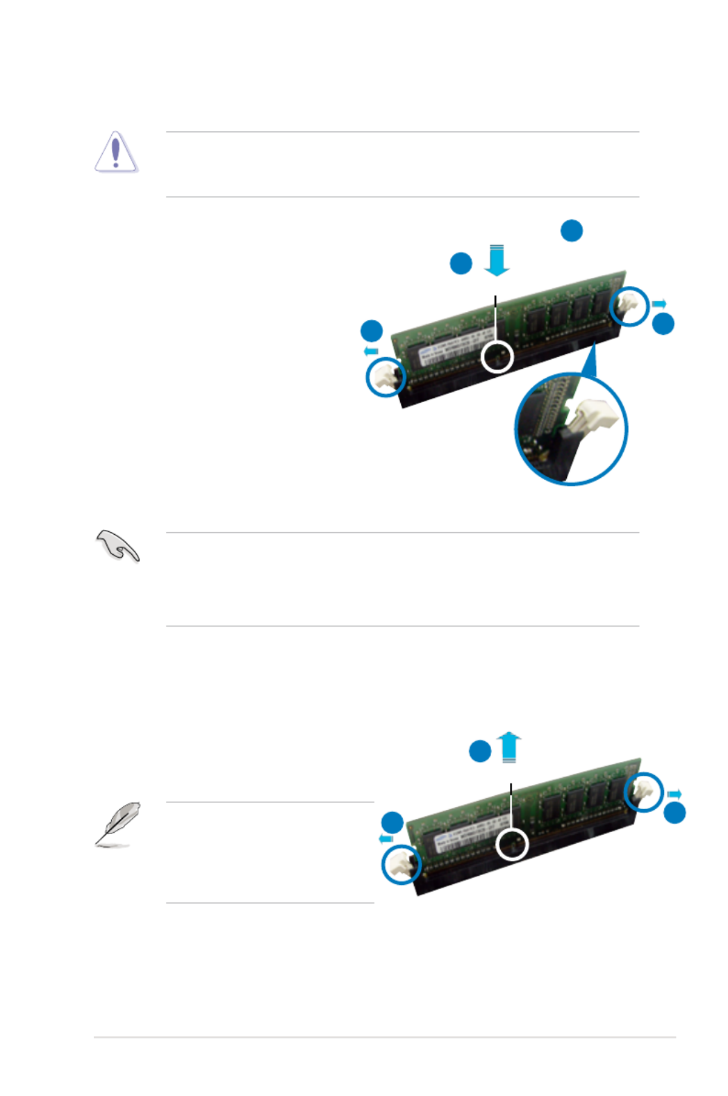
2.4.3 Installing a DIMM
To install a DIMM:
1. Unlock a DIMM socket by
pressing the retaining clips
outward.
2. Align a DIMM on the socket
such that the notch on the DIMM
matches the break on the socket.
3. Firmly insert the DIMM into the
socket until the retaining clips
snap back in place and the DIMM
is properly seated.
2.4.4 Removing a DIMM
To remove a DIMM:
1. Simultaneously press the retaining
clips outward to unlock the DIMM.
2. Remove the DIMM from the socket.
• A DDR3 DIMM is keyed with a notch so that it ts in only one direction. DO
NOT force a DIMM into a socket to avoid damaging the DIMM.
• The DDR3 DIMM sockets do not support DDR and DDR2 DIMMs. DO NOT
install DDR or DDR2 DIMMs to the DDR3 DIMM sockets.
Unplug the power supply before adding or removing DIMMs or other
system components. Failure to do so can cause severe damage to both the
motherboard and the components.
Support the DIMM lightly with
your ngers when pressing the
retaining clips. The DIMM might
get damaged when it ips out with
extra force.
Unlocked retaining clip
DDR3 DIMM notch
1
2
3
1
2
DDR3 DIMM notch
11

2-16 Chapter 2: Hardware information
2.5 Expansion slots
In the future, you may need to install expansion cards. The following sub-sections
describe the slots and the expansion cards that they support.
2.5.1 Installing an expansion card
To install an expansion card:
1. Before installing the expansion card, read the documentation that came with
it and make the necessary hardware settings for the card.
2. Remove the system unit cover (if your motherboard is already installed in a
chassis).
3. Remove the bracket opposite the slot that you intend to use. Keep the screw
for later use.
4. Align the card connector with the slot and press rmly until the card is
completely seated on the slot.
5. Secure the card to the chassis with the screw you removed earlier.
6. Replace the system cover.
2.5.2 Conguring an expansion card
After installing the expansion card, congure it by adjusting the software settings.
1. Turn on the system and change the necessary BIOS settings, if any. See
Chapter 4 for information on BIOS setup.
2. Assign an IRQ to the card. Refer to the tables on the next page.
3. Install the software drivers for the expansion card.
Make sure to unplug the power cord before adding or removing expansion
cards. Failure to do so may cause you physical injury and damage motherboard
components.
When using PCI cards on shared slots, ensure that the drivers support “Share
IRQ” or that the cards do not need IRQ assignments. Otherwise, conicts will
arise between the two PCI groups, making the system unstable and the card
inoperable. Refer to the table on the next page for details.

ASUS P5N64 WS Professional 2-17
2.5.3 Interrupt assignments
IRQ assignments for this motherboard
A B C D E F G H
PCI 1 shared – – – – – – –
PCI 2 shared– – – – – – –
1394 shared– – – – – – –
LAN 1 shared– – – – – – –
LAN 2 shared– – – – – – –
Marvell 6121 shared– – – – – – –
Marvell 6320 shared – – – – – – –
PCIe x16 1 shared – – – – – – –
PCIe x16 2 shared – – – – – –
PCIe x16 3 shared– – – – – – –
PCIe x16 4 shared– – – – – – –
PCIe x1 shared– – – – – – –
Azalia – – – – – – –shared
USB controller 1 shared– – – – – – –
USB controller 2 shared– – – – – – –
SATA controller 0 shared – – – – – – –
SATA controller 1 shared – – – – – – –
SATA controller 2 shared – – – – – – –
IRQ Priority Standard function
0 1 System timer
1 2 Keyboard controller
2 – Re-direct to IRQ#9
3 11 IRQ holder for PCI steering*
4 12 Communications port (COM1)*
5 13 IRQ holder for PCI steering*
6 14 Floppy disk controller
7 15 IRQ holder for PCI steering*
8 3 System CMOS/Real Time Clock
9 4 IRQ holder for PCI steering*
10 5 IRQ holder for PCI steering*
11 6 IRQ holder for PCI steering*
12 7 PS/2 compatible mouse port*
13 8 Numeric data processor
14 9 IRQ holder for PCI steering*
15 10 IRQ holder for PCI steering*
* These IRQs are usually available for PCI devices.
2-18 Chapter 2: Hardware information
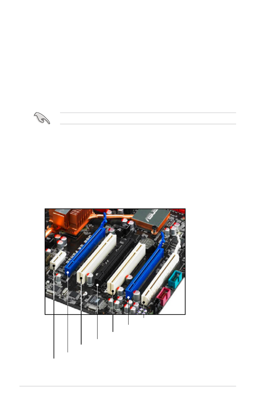
2.5.4 PCI slots
The PCI slots support cards such as a LAN card, SCSI card, USB card, and other
cards that comply with PCI specications. Refer to the gure below for the location
of the slots.
2.5.5 PCI Express p44-x1 slot
This motherboard supports PCI Express p44-x1 network cards, SCSI cards and other
cards that comply with the PCI Express specications. Refer to the gure below for
the location of the slot.
Install a PCIe p44-x1 device to a PCIe p44-x1 slot prior to a PCIe x16 slot.
2.5.6 PCI Express 2.0 x16 slots (blue)
This motherboard has two PCI Express 2.0 x16 slots that support PCI Express 2.0
x16 graphics cards complying with the PCI Express specications. Refer to the
gure below for the location of the slots.
2.5.7 Universal PCI Express x16 slots (black and white)
This motherboard also has two Universal PCI Express x16 slots with a maximum
speed of x16 (black) and p44-x8 (white) link. Refer to the gure below for the location
of the slots.
PCI Express x1_1 slot
PCIe 2.0 x16_1 slot (blue @ x16 link)
PCI_2 slot
Universal PCIe x16_2 slot (black @ x16 link)
PCI_1 slot
PCIe 2.0 x16_3 slot (blue @ x16 link)
Universal PCIe x16_4 slot (white @ p44-x8 link)

ASUS P5N64 WS Professional 2-19
• In single VGA card mode, use any of the PCIe 2.0 slots (blue) for a PCI
Express x16 graphics card to get better performance.
• In SLI™ mode, use the PCIe 2.0 slots (blue) for PCI Express x16 graphics
cards to get better performance.
• Use the two PCIe 2.0 slots (blue) and the black Universal PCIe x16 slot for
3-Way SLI™ mode.
• We recommend that you provide sufcient power when running SLI™
mode. See page 2-32 for details.
• Connect a chassis fan to the motherboard connector labeled
CHA_FAN1/2/3 when using multiple graphics cards for better thermal
environment. See page 2-30 for details.
• This motherboard supports the ASUS SASsaby cards (optional) for SAS
hard disk drive expansion. For SASsaby M, install the card to any of the
PCIe x16 slots (blue, black or white). For SASsaby 1064E, install the card
to the white Universal PCIe x16 slot only.

2-20 Chapter 2: Hardware information
• You do not need to clear the RTC when the system hangs due to
overclocking. For system failure due to overclocking, use the C.P.R. (CPU
Parameter Recall) feature. Shut down and reboot the system so the BIOS
can automatically reset parameter settings to default values.
• Due to the chipset limitation, AC power off is required prior using C.P.R.
function. You must turn off and on the power supply or unplug and plug the
power cord before reboot the system.
P5N64 WS PRO
P5N64 WS Professional Clear RTC RAM
1 2 2 3
Normal
(Default)
Clear RTC
CLRTC
2.6 Jumper
Clear RTC RAM (3-pin CLRTC)
This jumper allows you to clear the Real Time Clock (RTC) RAM in CMOS. You
can clear the CMOS memory of date, time, and system setup parameters by
erasing the CMOS RTC RAM data. The onboard button cell battery powers the
RAM data in CMOS, which include system setup information such as system
passwords.
To erase the RTC RAM:
1. Turn OFF the computer and unplug the power cord.
2. Move the jumper cap from pins 1-2 (default) to pins 2-3. Keep the cap on
pins 2-3 for about 5~10 seconds, then move the cap back to pins 1-2.
3. Plug the power cord and turn ON the computer.
4. Hold down the <Del> key during the boot process and enter BIOS setup
to re-enter data.
Except when clearing the RTC RAM, never remove the cap on CLRTC jumper
default position. Removing the cap will cause system boot failure!
If the steps above do not help, remove the onboard battery and move the
jumper again to clear the CMOS RTC RAM data. After the CMOS clearance,
reinstall the battery.
ASUS P5N64 WS Professional 2-21
2.7 Connectors
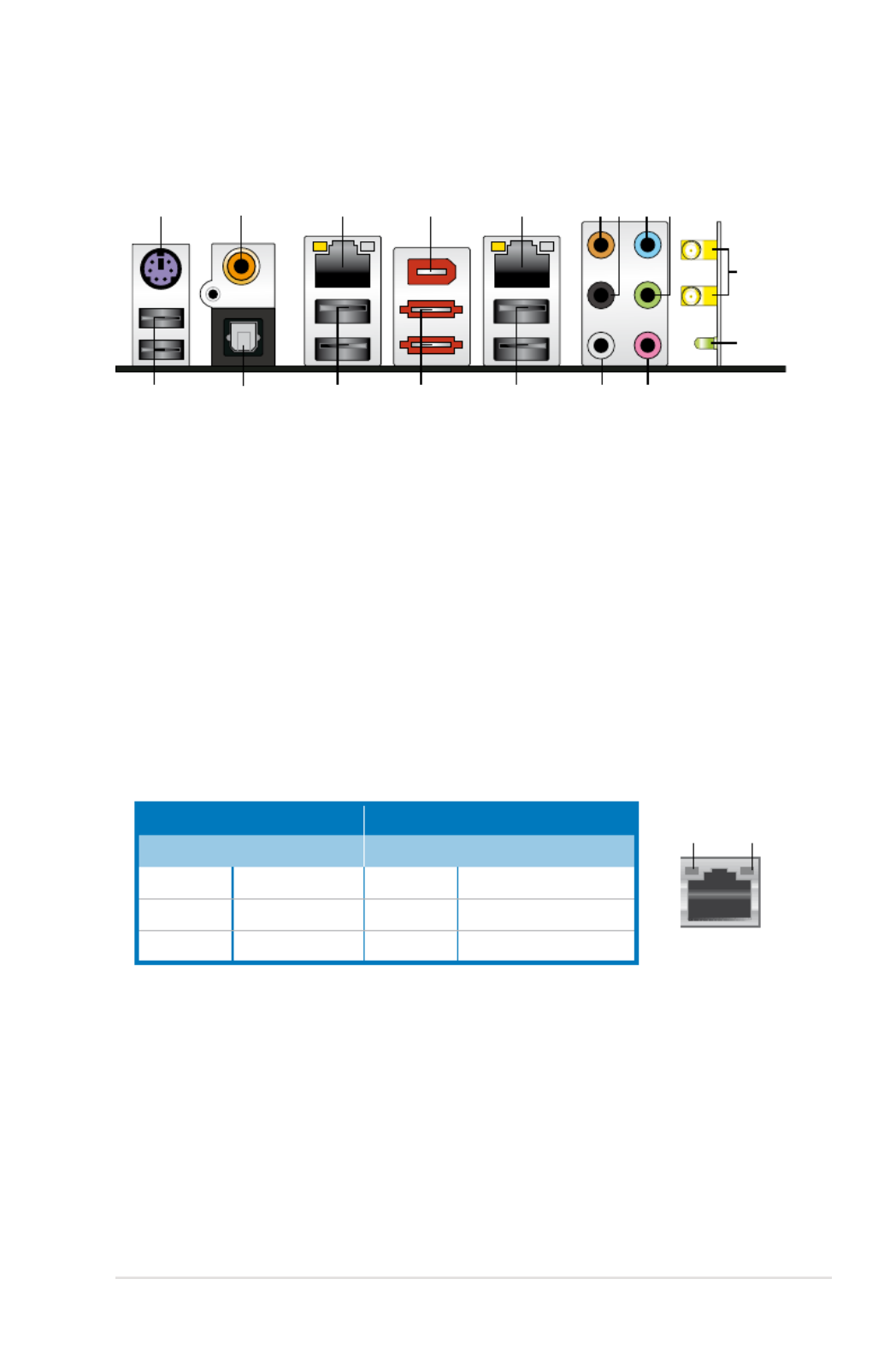
2.7.1 Rear panel connectors
1. PS/2 keyboard port (purple)PS/2 keyboard port (purple). This port is for a PS/2 keyboard.
2. Coaxial S/PDIF Out port. This port connects an external audio output device
via a coaxial S/PDIF cable.
3. LAN1 (RJ-45) port. Supported by Marvell ® Gigabit LAN controller, this port
allows Gigabit connection to a Local Area Network (LAN) through a network
hub. Refer to the table below for the LAN port LED indications.
4. IEEE1394a port. This 6-pin IEEE 1394a port provides high-speedThis 6-pin IEEE 1394a port provides high-speed
connectivity for audio/video devices, storage peripherals, PCs, or portable
devices..
5. LAN2 (RJ-45) port. Supported by Marvell ® Gigabit LAN controller, this port
allows Gigabit connection to a Local Area Network (LAN) through a network
hub. Refer to the table below for the LAN port LED indications.
6. Center/Subwoofer port (orange). This port connects the center/subwoofer
speakers.
7. Rear Speaker Out port (black). This port connects the rear speakers in a
4-channel, 6-channel, or 8-channel audio conguration.
8. Line In port (light blue). This port connects the tape, CD, DVD player, or
other audio sources.
9. Line Out port (lime). This port connects a headphone or a speaker. In
4-channel, 6-channel, and 8-channel conguration, the function of this port
becomes Front Speaker Out.
LAN port LED indications
SPEED
LED
ACT/LINK
LED
LAN port
21 54 6
15 1213
8 97
17 14
3
1618
10
11
Activity/Link LED Speed LED
Status Description Status Description
OFF No link OFF 10 Mbps connection
ORANGE Linked ORANGE 100 Mbps connection
BLINKING Data activity GREEN 1 Gbps connection

2-22 Chapter 2: Hardware information
10. Wireless LAN ports. These ports are on the onboard wireless LAN module
that allow you to set up a wireless network and exchange information
with other wireless devices without tagling cables and wires. Connect the
moveable omni-directional antennas to these ports.
11. Wireless LAN Activity LED. The wireless module comes with an activity
LED.
12. Microphone port (pink). This port connects a microphone.
13. Side Speaker Out port (gray). This port connects the side speakers in an
8-channel audio conguration.
14. USB 2.0 ports 1 and 2. These two 4-pin Universal Serial Bus (USB) ports
are available for connecting USB 2.0 devices.
15. External SATA ports. These ports connect to external Serial ATA hard disk
drives. To congure a RAID 0, 1, 5 or 10 set, install two external Serial ATA
hard disk drives or the port-multiplier device to these ports.
Refer to the audio conguration table below for the function of the audio ports in
2, 4, 6, or 8-channel conguration.
Audio 2, 4, 6, or 8-channel conguration
Port Headset
2-channel 4-channel 6-channel 8-channel
Light Blue Line In Line In Line In Line In
Lime Line Out Front Speaker Out Front Speaker Out Front Speaker Out
Pink Mic In Mic In Mic In Mic In
Orange Center/Subwoofer Center/Subwoofer– –
Black Rear Speaker Out Rear Speaker Ou Rear Speaker Out–
Gray Side Speaker Out– – –
• Before creating a RAID set using external Serial ATA hard disks, make
sure that you have connected the external Serial ATA signal cables and
installed external Serial ATA hard disk drives; otherwise, you cannot enter
the Marvell RAID utility during POST.
• If you intend to create a RAID set using the external SATA ports, set
the Marvell 6121/eSATA item in the BIOS to [RAID Mode]. See section
4.5.4 OnBoard Device Conguration and 5.4.3 Marvell ® eSATA RAID
congurations for details.
• DO NOT insert different connectors to these ports.
• DO NOT unplug the external Serial ATA drives when a RAID set is
congured.

ASUS P5N64 WS Professional 2-23
16. USB 2.0 ports 3 and 4 . These two 4-pin Universal Serial Bus (USB) ports
are available for connecting USB 2.0 devices.
17. Optical S/PDIF Out port. This port connects an external audio output device
via an optical S/PDIF cable.
18. USB 2.0 ports 5 and 6. These two 4-pin Universal Serial Bus (USB) ports
are available for connecting USB 2.0 devices.

2-24 Chapter 2: Hardware information
2.7.2 Internal connectors
1. Floppy disk drive connector (34-1 pin FLOPPY)
This connector is for the provided oppy disk drive (FDD) signal cable. Insert
one end of the cable to this connector, then connect the other end to the
signal connector at the back of the oppy disk drive.
Pin 5 on the connector is removed to prevent incorrect cable connection when
using a FDD cable with a covered Pin 5.
P5N64 WS PRO
FLOPPY
NOTE:Orient the red markings
on the floppy ribbon cable to PIN 1.
PIN1
P5N64 WS Professional Floppy disk drive connector

ASUS P5N64 WS Professional 2-25
• Pin 20 on the IDE connector is removed to match the covered hole on the
Ultra DMA cable connector. This prevents incorrect insertion when you
connect the IDE cable.
• Use the 80-conductor IDE cable for Ultra DMA 133/100 IDE devices.
If any device jumper is set as “Cable-Select,” make sure all other device
jumpers have the same setting.
2. IDE connector (40-1 pin PRI_IDE)
The onboard IDE connector is for the Ultra DMA 133/100 signal cable. There
are three connectors on each Ultra DMA 133/100 signal cable: blue, black,
and gray. Connect the blue connector to the motherboard’s IDE connector,
then select one of the following modes to congure your device.
Drive jumper setting Mode of
device(s) Cable connector
Single device Cable-Select or Master - Black
Two devices
Cable-Select Master Black
Slave Gray
Master Master Black or gray
Slave Slave
P5N64 WS PRO
PRI_IDE
NOTE:Orient the red markings
on the IDE ribbon cable to PIN 1.
PIN1
P5N64 WS Professional IDE connector

2-26 Chapter 2: Hardware information
3. nForce ® 790i Ultra SLI™ Serial ATA connectors [red] (7-pin SATA1-6)
These connectors are for the Serial ATA signal cables for Serial ATA hard disk
drives and optical disk drives.
• Refer to the table below for the recommended SATA hard disk drive
connections.
• These connectors are set to Standard IDE mode by default. In Standard
IDE mode, you can connect Serial ATA boot/data hard drives to these
connectors. If you intend to create a Serial ATA RAID set using these
connectors, set the nVIDIA RAID Function item in the BIOS to [Enabled].
See section for details.4.3.7 IDE Conguration
• Before creating a RAID set, refer to 5.4.2 NVIDIA ® RAID congurations or
the manual bundled in the motherboard support DVD.
P5N64 WS PRO
GND
RSATA_TXP1
RSATA_TXN1
GND
RSATA_RXP1
RSATA_RXN1
GND
SATA1 GND
RSATA_TXP2
RSATA_TXN2
GND
RSATA_RXP2
RSATA_RXN2
GND
SATA2
GND
RSATA_TXP3
RSATA_TXN3
GND
RSATA_RXP3
RSATA_RXN3
GND
SATA3 GND
RSATA_TXP4
RSATA_TXN4
GND
RSATA_RXP4
RSATA_RXN4
GND
SATA4
GND
RSATA_TXP5
RSATA_TXN5
GND
RSATA_RXP5
RSATA_RXN5
GND
SATA5 GND
RSATA_TXP6
RSATA_TXN6
GND
RSATA_RXP6
RSATA_RXN6
GND
SATA6
P5N64 WS Professional SATA connectors
Connect the right-angle side
of SATA signal cable to SATA
device. Or you may connect the
right-angle side of SATA cable to
the onboard SATA port to avoid
mechanical conict with huge
graphics cards.
right angle side
Serial ATA hard disk drive connection
Connector Color Setting Use
SATA 1/2 Red Master Boot disk
SATA 3/4 Red Master Boot disk
SATA 5/6 Red Master Boot disk

ASUS P5N64 WS Professional 2-27
4. Marvell® 88SE6320 SAS RAID connectors [yellow] (7-pin SAS1-2)
These connectors are for SAS (Serial Attached SCSI) signal cables that
support SAS hard disk drives. To congure RAID 0 or RAID 1, install two SAS
hard disk drives to these two connectors.
Before creating a RAID set using SAS hard disk drives, make sure that you
have connected the SAS signal cables and installed SAS hard disk drives;
otherwise, you cannot enter the Marvell RAID utility and SAS BIOS setup during
POST.
P5N64 WS PRO
GND
RSATA_TXP1
RSATA_TXN1
GND
RSATA_RXP1
RSATA_RXN1
GND
SAS1
GND
RSATA_TXP2
RSATA_TXN2
GND
RSATA_RXP2
RSATA_RXN2
GND
SAS2
P5N64 WS Professional SAS connectors
• Please install the Marvell® Controller driver before using the yellow SAS
RAID connectors (SAS1-2). Refer to for details.5.2.4 Make Disk menu
• Before creating a RAID set, refer to 5.4.4 Marvell
® SAS RAID
congurations or the manual bundled in the motherboard support DVD.
2-28 Chapter 2: Hardware information
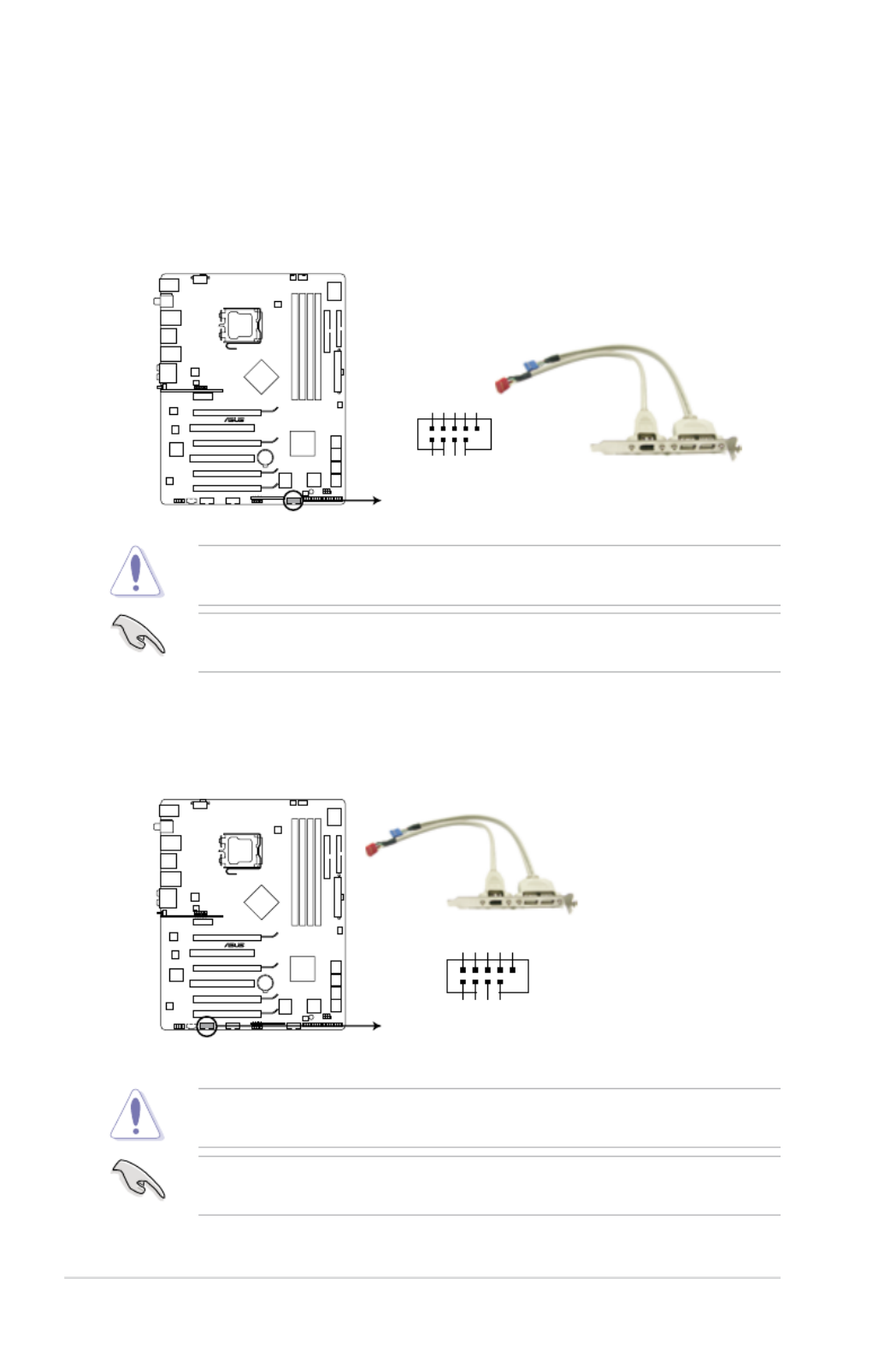
5. USB connector (10-1 pin USB 910)
This connector is for USB 2.0 ports. Connect the USB module cable to
this connector, then install the module to a slot opening at the back of the
system chassis. This USB connector complies with USB 2.0 specication that
supports up to 480 Mbps connection speed.
You can connect the USB cable to ASUS Q-Connector (USB, blue) rst, and
then install the Q-Connector (USB) to the USB connector onboard.
Never connect a 1394 cable to the USB connector. Doing so will damage the
motherboard!
P5N64 WS PRO
PIN 1
USB+5V
USB_P10-
USB_P10+
GND
NC
USB+5V
USB_P9-
USB_P9+
GND
USB910
P5N64 WS Professional USB2.0 connector
6. IEEE 1394a port connector (10-1 pin IE1394_2)
This connector is for an IEEE 1394a port. Connect the IEEE 1394a module
cable to this connector, then install the module to a slot opening at the back
of the system chassis.
Never connect a USB cable to the IEEE 1394a connector. Doing so will damage
the motherboard!
You can connect the 1394 cable to ASUS Q-Connector (1394, red) rst, and
then install the Q-Connector (1394) to the 1394 connector onboard.
P5N64 WS PRO
PIN 1
TPA2-
GND
TPB2-
+12V
GND
TPA2+
GND
TPB2+
+12V
IE1394_2
P5N64 WS Professional IEEE 1394 connector

ASUS P5N64 WS Professional 2-29
7. Optical drive audio connector (4-pin CD)
These connectors allow you to receive stereo audio input from sound sources
such as a CD-ROM, TV tuner, or MPEG card.
8. Serial port connector (10-1 pin COM1)
This connector is for a serial (COM) port. Connect the serial port module
cable to this connector, then install the module to a slot opening at the back
of the system chassis.
P5N64 WS PRO
P5N64 WS Professional Internal audio connector
CD
Left Audio Channel
GND
GND
Right Audio Channel
P5N64 WS PRO
PIN 1
COM1
P5N64 WS Professional Serial port2(COM1) connector
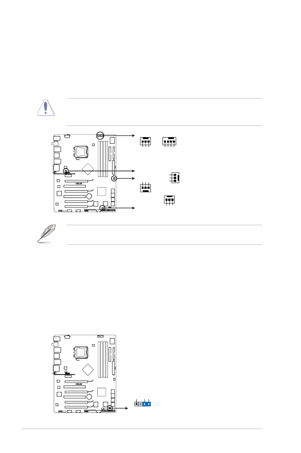
2-30 Chapter 2: Hardware information
9. CPU, chassis, and power fan connectors
(4-pin CPU_FAN, 3-pin CHA_FAN1-3, 3-pin PWR_FAN)
The fan connectors support cooling fans of 350 mA~2000 mA (24 W max.)
or a total of 1 A~7 A (84 W max.) at +12V. Connect the fan cables to the fan
connectors on the motherboard, making sure that the black wire of each
cable matches the ground pin of the connector.
Do not forget to connect the fan cables to the fan connectors. Insufcient air
ow inside the system may damage the motherboard components. These are
not jumpers! Do not place jumper caps on the fan connectors!
Only the CPU-FAN and CHA-FAN 1-2 connectors support the ASUS Q-FAN 2
feature.
P5N64 WS PRO
CPU_FAN
CHA_FAN1
CHA_FAN2
CHA_FAN3
PWR_FAN
CPU_FANPWR_FAN
Rotation
+12V
GND
Rotation
+12V
GND
Rotation
+12V
GND
CHA_FAN1 CHA_FAN2
CHA_FAN3
GND
+12V
Rotation
CPU FAN PWM
CPU FAN IN
CPU FAN PWR
GND
P5N64 WS Professional Fan connectors
10. Chassis intrusion connector (4-1 pin CHASSIS)
This connector is for a chassis-mounted intrusion detection sensor or switch.
Connect one end of the chassis intrusion sensor or switch cable to this
connector. The chassis intrusion sensor or switch sends a high-level signal to
this connector when a chassis component is removed or replaced. The signal
is then generated as a chassis intrusion event.
By default, the pin labeled “Chassis Signal” and “Ground” are shorted with
a jumper cap. Remove the jumper caps only when you intend to use the
chassis intrusion detection feature.
P5N64 WS PRO
+5VSB_MB
Chassis Signal
GND
CHASSIS
P5N64 WS Professional Chassis intrusion connector
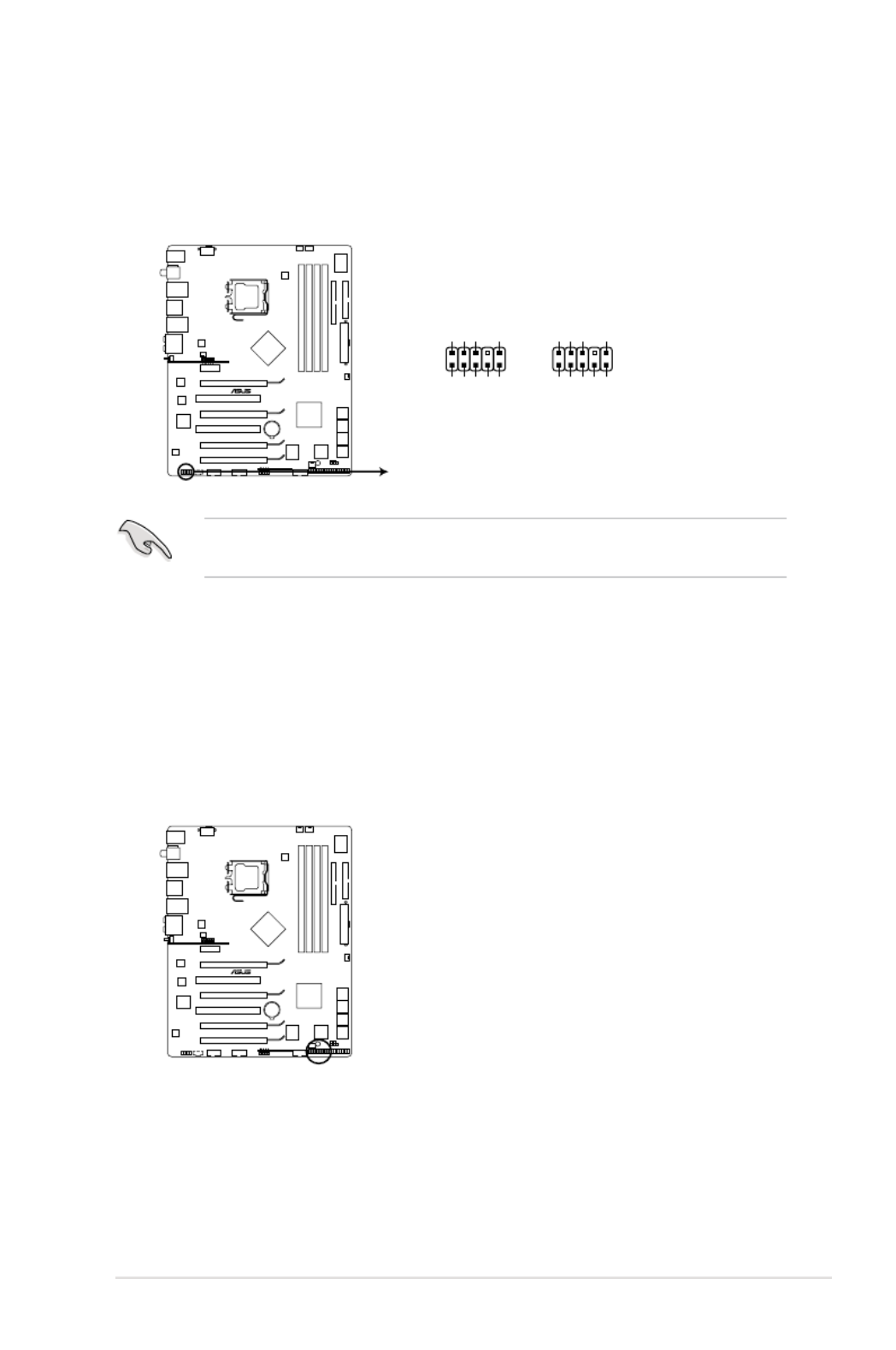
ASUS P5N64 WS Professional 2-31
11. Front panel audio connector (10-1 pin AAFP)
This connector is for a chassis-mounted front panel audio I/O module that
supports the HD Audio standard. Connect one end of the front panel audio
I/O module cable to this connector.
We recommend that you connect a high-denition front panel audio module to
this connector to avail of the motherboard’s high-denition audio capability.
P5N64 WS PRO
P5N64 WS Professional Analog front panel connector
AAFP
PIN 1
GND
PRESENCE#
SENSE1_RETUR
SENSE2_RETUR
PORT1 L
PORT1 R
PORT2 R
SENSE_SEND
PORT1 L
HD-audio-compliant
pin definition
PIN 1
AGND
NC
NC
NC
MIC2
MICPWR
Line out_R
NC
Line out_L
Legacy AC’97
compliant definition
12. TPM connector (20-1 pin TPM) [Optional]
This connector supports a Trusted Platform Module (TPM) system, which can
securely store keys, digital certicates, passwords, and data. A TPM system
also helps enhance network security, protects digital identities, and ensures
platform integrity.
P5N64 WS PRO
P5N64 WS Professional TPM connector
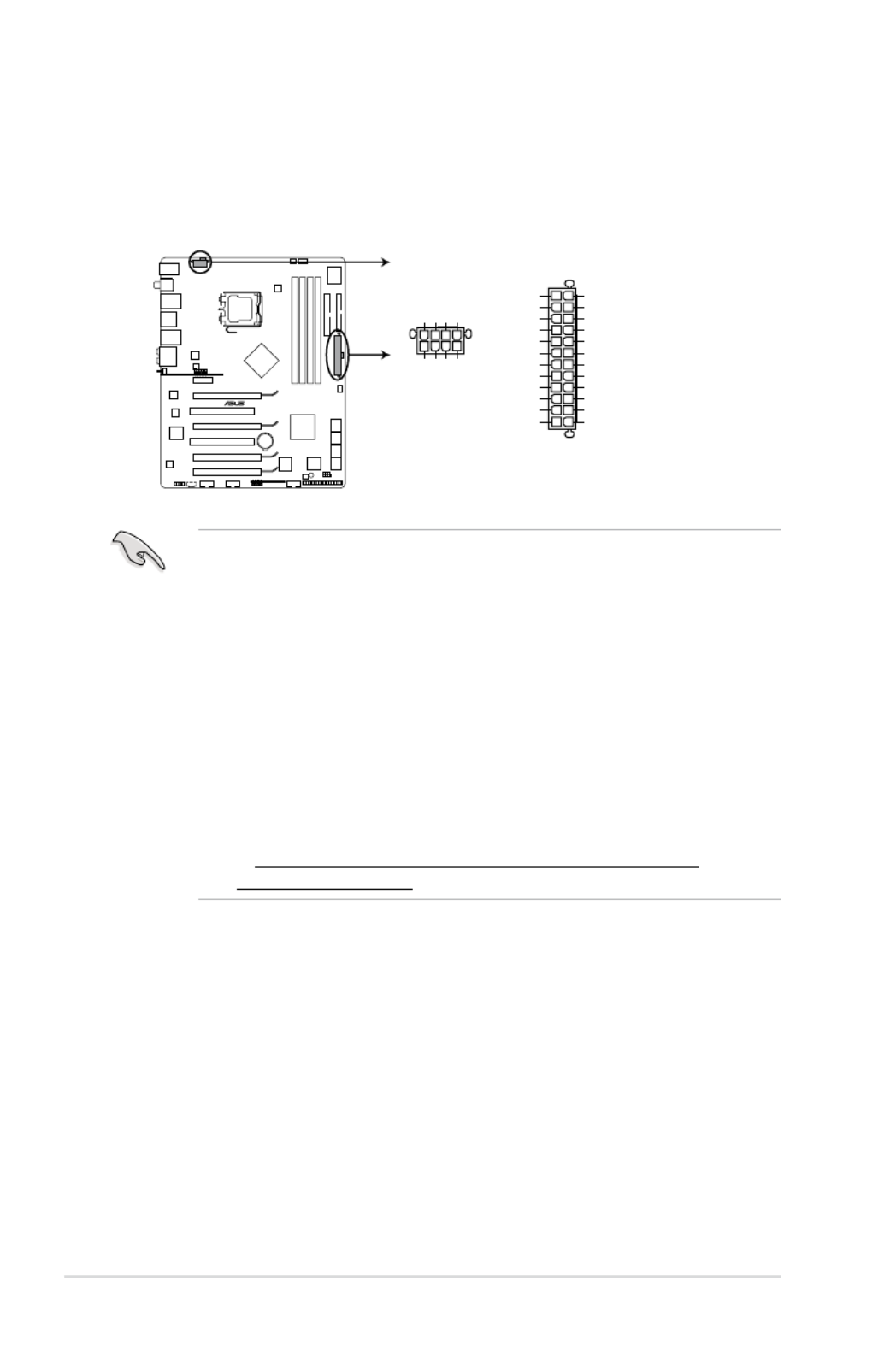
2-32 Chapter 2: Hardware information
• For a fully congured system, we recommend that you use a power supply
unit (PSU) that complies with ATX 12 V Specication 2.0 (or later version)
and provides a minimum power of 400 W.
• Do not forget to connect the 8-pin EATX12V power plug; otherwise, the
system will not boot.
• Use of a PSU with a higher power output is recommended when
conguring a system with more power-consuming devices. The system
may become unstable or may not boot up if the power is inadequate.
• If you want to use two high-end PCI Express x16 cards, use a PSU with
500W to 600W power or above to ensure the system stability.
• If you are uncertain about the minimum power supply requirement for your
system, refer to the Recommended Power Supply Wattage Calculator
at http://support.asus.com/PowerSupplyCalculator/PSCalculator.
aspx?SLanguage=en-us for details.
13. ATX power connectors (24-pin EATXPWR, 8-pin EATX12V)
These connectors are for ATX power supply plugs. The power supply plugs
are designed to t these connectors in only one orientation. Find the proper
orientation and push down rmly until the connectors completely t.
P5N64 WS PRO
EATXPWR
PIN 1
GND
+5 Volts
+5 Volts
+5 Volts
-5 Volts
GND
GND
GND
PSON#
GND
-12 Volts
+3 Volts
+3 Volts
+12 Volts
+12 Volts
+5V Standby
Power OK
GND
+5 Volts
GND
+5 Volts
GND
+3 Volts
+3 Volts
EATX12V
PIN 1
+12V DC
+12V DC
+12V DC
+12V DC
GND
GND
GND
GND
P5N64 WS Professional ATX power connectors

ASUS P5N64 WS Professional 2-33
• System power LED (2-pin PLED)
This 2-pin connector is for the system power LED. Connect the chassis
power LED cable to this connector. The system power LED lights up when
you turn on the system power, and blinks when the system is in sleep mode.
• Hard disk drive activity LED (2-pin IDE_LED)
This 2-pin connector is for the HDD Activity LED. Connect the HDD Activity
LED cable to this connector. The IDE LED lights up or ashes when data is
read from or written to the HDD.
• System warning speaker (4-pin SPEAKER)
This 4-pin connector is for the chassis-mounted system warning speaker. The
speaker allows you to hear system beeps and warnings.
• ATX power button/soft-off button (2-pin PWRSW)
This connector is for the system power button. Pressing the power button
turns the system on or puts the system in sleep or soft-off mode depending
on the BIOS settings. Pressing the power switch for more than four seconds
while the system is ON turns the system OFF.
• Reset button (2-pin RESET)
This 2-pin connector is for the chassis-mounted reset button for system
reboot without turning off the system power.
14. System panel connector (20-8 pin PANEL)
This connector supports several chassis-mounted functions.
P5N64 WS PRO
PIN 1
* Requires an ATX power supply
PLED SPEAKER
PLED+
PLED-
+5V
Ground
Ground
Speaker
IDE_LED+
IDE_LED-
PWR
Ground
Reset
Ground
PANEL
IDE_LED PWRSW RESET
P5N64 WS Professional System panel connector

2-34 Chapter 2: Hardware information
15. Q-Connector (system panel)
You can use ASUS Q-Connector to connect / disconnect chassis front panel
cables by only a few steps. Directions below shows how to install ASUS Q-
Connector.
Step2.
Properly install the ASUS Q-Connector to the
System panel connctor.
Step1.
Connect correct front panel to ASUS Q-
Connector rst. You can refer to the marking
on Q-Connector itself to know the detail pin
denition.
Step3.
Front panel functions are enabled.

ASUS P5N64 WS Professional 2-35
2.8 G.P. Diagnosis card installation
2.8.1 G.P. Diagnosis card layout
1. Locate the TPM connector (20-1
pin TPM) on the motherboard.
2. With the LEDs of the diagnosis
card facing to the DIMM sockets,
align the card connector with the
TPM connector and press rmly
until the card sits on the connector
completely.
Make sure to turn off the power supply unit before instaling the diagnosis card to
avoid electrical shock hazard.
2.8.2 Installing G.P. Diagnosis card
LED 0 and 1
Card connector
Power Switch. Press
to turn ON or OFF the
computer.
Reset Button.
Press to restart the
computer.
P5N64 WS PRO
P5N64 WS Professional TPM connector

2-36 Chapter 2: Hardware information
2.8.3 G.P. Diagnosis card check codes
D0 75Initiate chip Detect IDE
D1 78Enable IO device for bootlock Initiate option ROM
D2 85Check and wake up system Show post error
D3 Prepare system for memory
detection and sizing
87 Enter BIOS setup
A4 BIOS boot menu
D4 ACMemory test OS in PIC mode
D5 AACopy BIOS from ROM to RAM OS in APIC mode
C0 01Early CPU initiation S1
C5 Wake up AP S303
0A 04Initiate KBC8042 S4
0B 05Detect PS2 mouse S5
0C 10Detect PS2 keyboard Resume from S1
38 30USB initiation Resume from S3
52 40Display USB devices Resume from S4
2A Initiate VGA BIOS Leave BIOS and pass control to OS00
3. You may also install the G.P.
Diagnosis card via a bundled 90-
degree TPM adaptor for a more
exible application.

3
Chapter 3:
Powering up
This chapter describes the power up
sequence, the vocal POST messages,
and ways of shutting down the system.

ASUS P5N64 WS Professional
Chapter summary
3
3.1 Starting up for the rst time ........................................................ 3-1
3.2 Turning off the computer ............................................................. 3-2

ASUS P5N64 WS Professional 3-1
3.1 Starting up for the rst time
1. After making all the connections, replace the system case cover.
2. Be sure that all switches are off.
3. Connect the power cord to the power connector at the back of the system
chassis.
4. Connect the power cord to a power outlet that is equipped with a surge
protector.
5. Turn on the devices in the following order:
a. Monitor
b. External SCSI devices (starting with the last device on the chain)
c. System power
6. After applying power, the system power LED on the system front panel case
lights up. For systems with ATX power supplies, the system LED lights up
when you press the ATX power button. If your monitor complies with “green”
standards or if it has a “power standby” feature, the monitor LED may light up
or switch between orange and green after the system LED turns on.
The system then runs the power-on self tests or POST. While the tests are
running, the BIOS beeps (see BIOS beep codes table below) or additional
messages appear on the screen. If you do not see anything within 30
seconds from the time you turned on the power, the system may have failed a
power-on test. Check the jumper settings and connections or call your retailer
for assistance.
7. At power on, hold down the <Delete> key to enter the BIOS Setup. Follow the
instructions in Chapter 4.
BIOS Beep Description
One short beep VGA detected
Quick boot set to disabled
No keyboard detected
One continuous beep followed by two
short beeps then a pause (repeated)
No memory detected
One continuous beep followed by three
short beeps
No VGA detected
One continuous beep followed by four
short beeps
Hardware component failure
AMI BIOS beep codes

3-2 Chapter 3: Powering up
3.2 Turning off the computer
3.2.1 Using the OS shut down function
If you are using Windows® XP or later version:
1. Click the Start button then select Turn Off Computer.
2. Click the Turn Off button to shut down the computer.
3. The power supply should turn off after Windows
® shuts down.
If you are using Windows® Vista:
1. Click the Start button then select ShutDown.
2. The power supply should turn off after Windows
® shuts down.
3.2.2 Using the dual function power switch
While the system is ON, pressing the power switch for less than four seconds puts
the system to sleep mode or to soft-off mode, depending on the BIOS setting.
Pressing the power switch for more than four seconds lets the system enter the
soft-off mode regardless of the BIOS setting. Refer to section
4.6 Power Menu in
Chapter 4 for details.

4
Chapter 4: BIOS setup
This chapter tells how to change the
system settings through the BIOS Setup
menus. Detailed descriptions of the BIOS
parameters are also provided.

Chapter summary
4
ASUS P5N64 WS Professional
4.1 Managing and updating your BIOS ............................................ 4-1
4.2 BIOS setup program .................................................................... 4-9
4.3 Main menu .................................................................................. 4-12
4.4 Ai Tweaker menu ... .................................................................... 4-17
4.5 Advanced menu ......................................................................... 4-21
4.6 Power menu ................................................................................ 4-26
4.7 Boot menu .................................................................................. 4-30
4.8 Tools menu ................................................................................. 4-34
4.9 Exit menu .................................................................................... 4-38

ASUS P5N64 WS Professional 4-1
4.1 Managing and updating your BIOS
The following utilities allow you to manage and update the motherboard Basic
Input/Output System (BIOS) setup.
1. (Updates the BIOS in WindowsASUS Update ® environment.)
2. ASUS EZ Flash 2 (Updates the BIOS using a oppy disk or USB ash disk.)
3. ASUS AFUDOS (Updates the BIOS using a bootable oppy disk.)
4. ASUS CrashFree BIOS 3 (Updates the BIOS using a bootable oppy disk,
USB ash disk or the motherboard support DVD when the BIOS le fails or
gets corrupted.)
Refer to the corresponding sections for details on these utilities.
Save a copy of the original motherboard BIOS le to a bootable oppy disk or
USB ash disk in case you need to restore the BIOS in the future. Copy the
original motherboard BIOS using the ASUS Update or AFUDOS utilities.
Installing ASUS Update
To install ASUS Update:
1. Place the support DVD in the optical drive. The Drivers menu appears.
2. Click the Utilities tab, then click Install ASUS Update VX.XX.XX.
3. The ASUS Update utility is copied to your system.
4.1.1 ASUS Update utility
The ASUS Update is a utility that allows you to manage, save, and update the
motherboard BIOS in Windows® environment. The ASUS Update utility allows you
to:
• Save the current BIOS le
• Download the latest BIOS le from the Internet
• Update the BIOS from an updated BIOS le
• Update the BIOS directly from the Internet, and
• View the BIOS version information.
This utility is available in the support DVD that comes with the motherboard
package.
ASUS Update requires an Internet connection either through a network or an
Internet Service Provider (ISP).

4-2 Chapter 4: BIOS setup
Quit all Windows® applications before you update the BIOS using this utility.
3. Select the ASUS FTP site nearest
you to avoid network trafc, or
click . Click .Auto Select Next
Updating the BIOS through the Internet
To update the BIOS through the Internet:
1. Launch the ASUS Update utility from the Windows
® desktop by clicking Start
> Programs > ASUS > ASUSUpdate > ASUSUpdate. The ASUS Update
main window appears.
2. Select from the Update BIOS
Internet option from the drop-down
menu, then click .Next

ASUS P5N64 WS Professional 4-3
Updating the BIOS through a BIOS le
To update the BIOS through a BIOS le:
1. Launch the ASUS Update utility from the Windows
® desktop by clicking Start
> Programs > ASUS > ASUSUpdate > ASUSUpdate. The ASUS Update
main window appears.
2. Select Update BIOS from a le
option from the drop-down menu,
then click .Next
4. From the FTP site, select the BIOS
version that you wish to download.
Click .Next
5. Follow the screen instructions to
complete the update process.
The ASUS Update utility is
capable of updating itself through
the Internet. Always update the
utility to avail all its features.
3. Locate the BIOS le from the Open
window, then click .Open
4. Follow the screen instructions to
complete the update process.
P5E64WP
P5E64WP.ROM

4-4 Chapter 4: BIOS setup
4.1.2 Creating a bootable oppy disk
1. Do either one of the following to create a bootable oppy disk.
DOS environment
a. Insert a 1.44MB oppy disk into the drive.
b. At the DOS prompt, type
format
/A: S then press <Enter>.
Windows
®
XP environment
a. Insert a 1.44 MB oppy disk to the oppy disk drive.
b. Click from the WindowsStart ® desktop, then select .My Computer
c. Select the 3 1/2 Floppy Drive icon.
d. Click File from the menu, then select . A Format Format 3 1/2 Floppy
Disk window appears.
e. Select Create an MS-DOS startup disk from the format options eld,
then click .Start
Windows
®
Vista environment
a. Insert a formatted, high density 1.44 MB oppy disk to the oppy disk
drive.
b. Click from the Windows® desktop, then select .Computer
c. Right-click then click to display the Floppy Disk Drive Format Format 3
1/2 Floppy dialog box .
d. Select the check box.Create an MS-DOS startup disk
e. Click .Start
2. Copy the original or the latest motherboard BIOS le to the bootable oppy
disk.

ASUS P5N64 WS Professional 4-5
To update the BIOS using EZ Flash 2:
1. Visit the ASUS website (www.asus.com) to download the latest BIOS le for
the motherboard.
2. Save the BIOS le to a oppy disk or a USB ash disk, then restart the
system.
4.1.3 ASUS EZ Flash 2 utility
The ASUS EZ Flash 2 feature allows you to update the BIOS without having to go
through the long process of booting from a oppy disk and using a DOS-based
utility. The EZ Flash 2 utility is built in the BIOS chip so it is accessible by pressing
<Alt> + <F2> during the Power-On Self Tests (POST).
(2) Enter BIOS setup program. Go to the Tools EZ Flash 2 menu to select
and press <Enter> to enable it.
You can switch between drives by pressing <Tab> before the correct le
is found. Then press <Enter>.
3. You can launch the EZ Flash 2 by two methods.
(1) Insert the oppy disk / USB ash disk that contains the BIOS le to the
oppy disk drive or the USB port.
Press <Alt> + <F2> during POST to display the following.
• This function can support devices such as a USB ash disk or a oppy disk
with FAT 32/16 format and single partition only.
• Do not shut down or reset the system while updating the BIOS to prevent
system boot failure!
4. When the correct BIOS le is found, EZ Flash 2 performs the BIOS update
process and automatically reboots the system when done.
ASUSTek EZ Flash 2 BIOS ROM Utility V3.24
Current ROM Update ROM
A:
C:
Note
[Enter] Select or Load [B] Backup [ESC] Exit
[Tab] Switch [Up/Down/Home/End] Move
FLASH TYPE: SST 49LF080/A LPC
PATH: A:\
BOARD: P5N64-WS PRO
VER: 0136
DATE: 03/19/2008
BOARD: Unknown
VER: Unknown
DATE: Unknown

4-6 Chapter 4: BIOS setup
4.1.4 AFUDOS utility
The AFUDOS utility allows you to update the BIOS le in DOS environment using
a bootable oppy disk with the updated BIOS le. This utility also allows you to
copy the current BIOS le that you can use as backup when the BIOS fails or gets
corrupted during the updating process.
Copying the current BIOS
To copy the current BIOS le using the AFUDOS utility:
Main lename Extension name
1. Copy the AFUDOS utility (afudos.exe) from the motherboard support DVD to
the bootable oppy disk you created earlier.
2. Boot the system in DOS mode, then at the prompt type:
afudos /o[lename]
where the [lename] is any user-assigned lename not more than eight
alphanumeric characters for the main lename and three alphanumeric
characters for the extension name.
A:\>afudos /oOLDBIOS1.rom
• Make sure that the oppy disk is not write-protected and has at least
1024KB free space to save the le.
• The succeeding BIOS screens are for reference only. The actual BIOS
screen displays may not be same as shown.
The utility returns to the DOS prompt after copying the current BIOS le.
3. Press <Enter>. The utility copies the current BIOS le to the oppy disk.
A:\>afudos /oOLDBIOS1.rom
AMI Firmware Update Utility - Version 1.19(ASUS V2.07(03.11.24BB))
Copyright (C) 2002 American Megatrends, Inc. All rights reserved.
Reading ash ..... done
Write to le...... ok
A:\>
Updating the BIOS le
To update the BIOS le using the AFUDOS utility:
1. Visit the ASUS website (www.asus.com) and download the latest BIOS le for
the motherboard. Save the BIOS le to a bootable oppy disk.

ASUS P5N64 WS Professional 4-7
2. Copy the AFUDOS utility (afudos.exe) from the motherboard support DVD to
the bootable oppy disk you created earlier.
3. Boot the system in DOS mode, then at the prompt type:
afudos /i[lename]
where [lename] is the latest or the original BIOS le on the bootable oppy
disk.
A:\>afudos /iP5N64WP.ROM
Write the BIOS lename on a piece of paper. You need to type the exact BIOS
lename at the DOS prompt.
5. The utility returns to the DOS prompt after the BIOS update process is
completed. Reboot the system from the hard disk drive.
A:\>afudos /iP5N64WP.ROM
AMI Firmware Update Utility - Version 1.19(ASUS V2.07(03.11.24BB))
Copyright (C) 2002 American Megatrends, Inc. All rights reserved.
WARNING!! Do not turn off power during ash BIOS
Reading le ....... done
Reading ash ...... done
Advance Check ......
Erasing ash ...... done
Writing ash ...... done
Verifying ash .... done
Please restart your computer
A:\>
A:\>afudos /iP5N64WP.ROM
AMI Firmware Update Utility - Version 1.19(ASUS V2.07(03.11.24BB))
Copyright (C) 2002 American Megatrends, Inc. All rights reserved.
WARNING!! Do not turn off power during ash BIOS
Reading le ....... done
Reading ash ...... done
Advance Check ......
Erasing ash ...... done
Writing ash ...... 0x0008CC00 (9%)
4. The utility veries the le and starts updating the BIOS.
Do not shut down or reset the system while updating the BIOS to prevent
system boot failure!

4-8 Chapter 4: BIOS setup
4.1.5 ASUS CrashFree BIOS 3 utility
The ASUS CrashFree BIOS 3 is an auto recovery tool that allows you to restore
the BIOS le when it fails or gets corrupted during the updating process. You can
update a corrupted BIOS le using the motherboard support DVD or the USB ash
disk that contains the updated BIOS le.
Prepare the motherboard support DVD, the oppy disk or the USB ash disk
containing the updated motherboard BIOS before using this utility.
Recovering the BIOS from the support DVD
To recover the BIOS from the support DVD:
1. Turn on the system.
2. Insert the motherboard support DVD to the optical drive.
3. The utility displays the following message and automatically checks the DVD
for the BIOS le.
4. Restart the system after the utility completes the updating process.
• Only the USB ash disk with FAT 32/16 format and single partition can
support ASUS CrashFree BIOS 3. The device size should be smaller than
8GB.
• DO NOT shut down or reset the system while updating the BIOS! Doing so
can cause system boot failure!
When found, the utility reads the BIOS le and starts ashing the corrupted
BIOS le.
Recovering the BIOS from the USB ash disk
To recover the BIOS from the USB ash disk:
1. Insert the USB ash disk that contains the BIOS le to the USB port.
2. Turn on the system.
3. The utility will automatically checks the devices for the BIOS le. When
found, the utility reads the BIOS le and starts ashing the corrupted BIOS
le.
4. Restart the system after the utility completes the updating process.
Bad BIOS checksum. Starting BIOS recovery...
Checking for oppy...
Bad BIOS checksum. Starting BIOS recovery...
Checking for oppy...
Floppy found!
Reading le “P5N64WP.ROM”. Completed.
Start ashing...

ASUS P5N64 WS Professional 4-9
4.2 BIOS setup program
This motherboard supports a programmable rmware chip that you can update
using the provided utility described in section 4.1 Managing and updating your
BIOS.
Use the BIOS Setup program when you are installing a motherboard, reconguring
your system, or prompted to “Run Setup.” This section explains how to congure
your system using this utility.
Even if you are not prompted to use the Setup program, you can change the
conguration of your computer in the future. For example, you can enable the
security password feature or change the power management settings. This
requires you to recongure your system using the BIOS Setup program so that the
computer can recognize these changes and record them in the CMOS RAM.
The SPI chip on the motherboard stores the Setup utility. When you start up the
computer, the system provides you with the opportunity to run this program. Press
<Del> during the Power-On Self-Test (POST) to enter the Setup utility; otherwise,
POST continues with its test routines.
If you wish to enter Setup after POST, restart the system by pressing
<Ctrl+Alt+Delete>, or by pressing the reset button on the system chassis. You can
also restart by turning the system off and then back on. Do this last option only if
the rst two failed.
The Setup program is designed to make it as easy to use as possible. Being a
menu-driven program, it lets you scroll through the various sub-menus and make
your selections from the available options using the navigation keys.
• The default BIOS settings for this motherboard apply for most conditions
to ensure optimum performance. If the system becomes unstable after
changing any BIOS settings, load the default settings to ensure system
compatibility and stability. Select the Load Default Settings item under the
Exit Menu. See section .4.9 Exit Menu
• The BIOS setup screens shown in this section are for reference purposes
only, and may not exactly match what you see on your screen.
• Visit the ASUS website (www.asus.com) to download the latest BIOS le for
this motherboard.
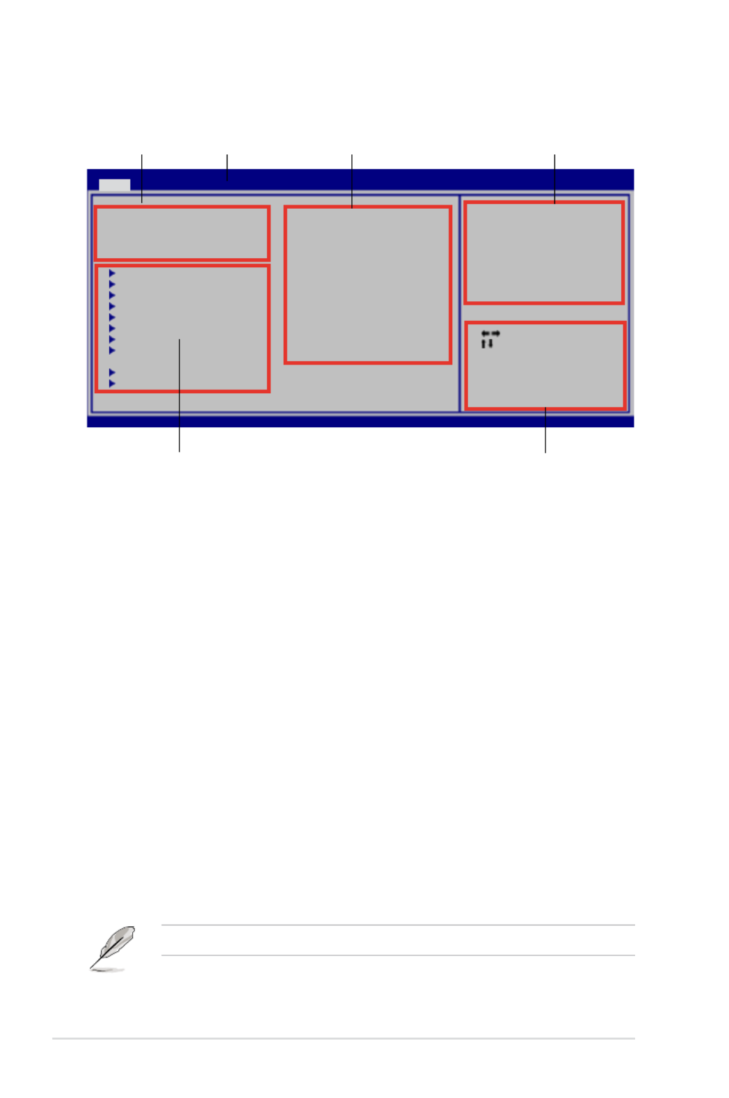
4-10 Chapter 4: BIOS setup
4.2.2 Menu bar
The menu bar on top of the screen has the following main items:
Main For changing the basic system conguration
Ai Tweaker For changing the system performance settings
Advanced For changing the advanced system settings
Power For changing the advanced power management (APM)
conguration
Boot For changing the system boot conguration
Tools For conguring special system functions
Exit For selecting the exit options and loading default settings
To select an item on the menu bar, press the right or left arrow key on the keyboard
until the desired item is highlighted.
4.2.3 Navigation keys
At the bottom right corner of a menu screen are the navigation keys for that
particular menu. Use the navigation keys to select items in the menu and change
the settings.
4.2.1 BIOS menu screen
Some of the navigation keys differ from one screen to another.
Select Screen
Select Item
+- Change Field
Tab Select Field
F1 General Help
F10 Save and Exit
ESC Exit
v02.61 (C)Copyright 1985-2008, American Megatrends, Inc.
BIOS SETUP UTILITY
Main Ai Tweaker Advanced Power Boot Tools Exit
System Time [10:55:25]
System Date [Thu 03/06/2008]
Legacy Diskette A [1.44M, 3.5 in]
Language [English]
Primary IDE Master : [Not Detected]
Primary IDE Slave : [Not Detected]
SATA 1 : [HDT722516DLA380]
SATA 2 : [Not Detected]
SATA 3 : [Not Detected]
SATA 4 : [Not Detected]
SATA 5 : [Not Detected]
SATA 6 : [Not Detected]
IDE Coniguration
System Information
Use [ENTER], [TAB]
or [SHIFT-TAB] to
select a eld.
Use [+] or [-] to
congure system Time.
Navigation keys
General help
Menu bar
Sub-menu items
Conguration eldsMenu items
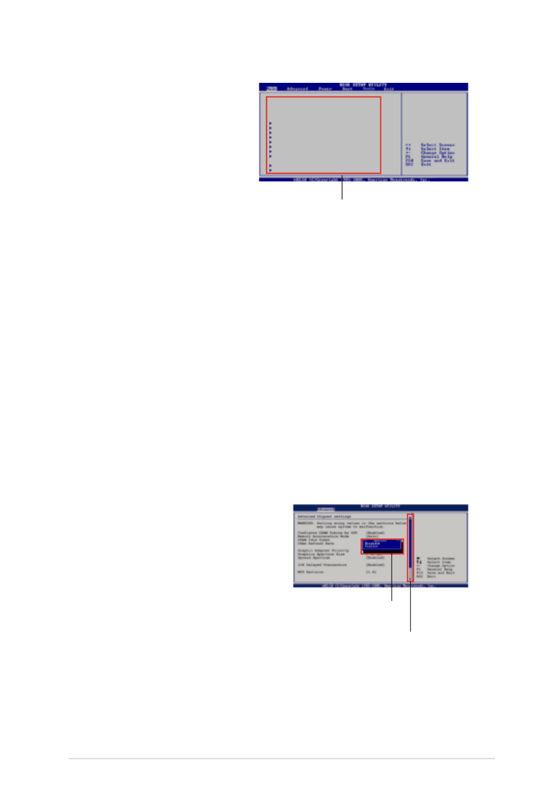
ASUS P5N64 WS Professional 4-11
4.2.4 Menu items
The highlighted item on the menu
bar displays the specic items for
that menu. For example, selecting
Main shows the Main menu items.
The other items (Advanced, Power,
Boot, and Exit) on the menu bar
have their respective menu items.
4.2.5 Sub-menu items
A solid triangle before each item on any menu screen means that the iteam has a
sub-menu. To display the sub-menu, select the item and press <Enter>.
4.2.6 Conguration elds
These elds show the values for the menu items. If an item is user- congurable,
you can change the value of the eld opposite the item. You cannot select an item
that is not user-congurable.
A congurable eld is enclosed in brackets, and is highlighted when selected. To
change the value of a eld, select it then press <Enter> to display a list of options.
Refer to .4.2.7 Pop-up window
4.2.7 Pop-up window
Select a menu item then press <Enter> to display a pop-up window with the
conguration options for that item.
4.2.8 Scroll bar
A scroll bar appears on the right side of a
menu screen when there are items that do
not t on the screen. Press the
Up/Down arrow keys or <Page Up> /<Page
Down> keys to display the other items on
the screen.
4.2.9 General help
At the top right corner of the menu screen
is a brief description of the selected item. Scroll bar
Pop-up window
Main menu items
System Time [06:22:54]
System Date [Wed 03/06/2008]
Floppy Diskette A [1.44M, 3.5 in.]
Language [English]
Primary IDE Master : [Not Detected]
Primary IDE Slave : [Not Detected]
SATA1 : [Not Detected]
SATA2 : [Not Detected]
SATA3 : [Not Detected]
SATA4 : [Not Detected]
SATA5 : [Not Detected]
SATA6 : [Not Detected]
IDE Conguration
System Information
Use [ENTER], [TAB],
or [SHIFT-TAB] to
select a eld.
Use [+] or [-] to
congure system.

4-12 Chapter 4: BIOS setup
4.3 Main menu
When you enter the BIOS Setup program, the Main menu screen appears, giving
you an overview of the basic system information.
4.3.1 System Time [xx:xx:xx]
Allows you to set the system time.
4.3.2 System Date [Day xx/xx/xxxx]
Allows you to set the system date.
4.3.3 Legacy Diskette A [1.44M, 3.5 in.]
Sets the type of oppy drive installed.
Conguration options: [Disabled] [720K, 3.5 in.] [1.44M, 3.5 in.]
4.3.4 Language [English]
Allows you to choose the BIOS language version from the options.
Conguration options: [Chinese BIG5] [Chinese (GB)] [Japanese] [Français]
[German] [English]
Refer to section for information on the menu screen 4.2.1 BIOS menu screen
items and how to navigate through them.
Select Screen
Select Item
+- Change Field
Tab Select Field
F1 General Help
F10 Save and Exit
ESC Exit
v02.61 (C)Copyright 1985-2008, American Megatrends, Inc.
BIOS SETUP UTILITY
Main Ai Tweaker Advanced Power Boot Tools Exit
Use [ENTER], [TAB] or
[SHIFT-TAB] to select
a eld.
Use [+] or [-] to
congure system Time.
System Time [10:55:25]
System Date [Wed 03/06/2008]
Legacy Diskette A [1.44M, 3.5 in]
Language [English]
Primary IDE Master : [Not Detected]
Primary IDE Slave : [Not Detected]
SATA 1 : [HDT722516DLA380]
SATA 2 : [Not Detected]
SATA 3 : [Not Detected]
SATA 4 : [Not Detected]
SATA 5 : [Not Detected]
SATA 6 : [Not Detected]
IDE Conguration
System Information

ASUS P5N64 WS Professional 4-13
4.3.5 Primary IDE Master/Slave
While entering Setup, the BIOS automatically detects the presence of IDE devices.
There is a separate sub-menu for each IDE device. Select a device item then
press <Enter> to display the IDE device information.
The BIOS automatically detects the values opposite the dimmed items (Device,
Vendor, Size, LBA Mode, Block Mode, PIO Mode, Async DMA, Ultra DMA, and
SMART monitoring). These values are not user-congurable. These items show
N/A if no IDE device is installed in the system.
Type [Auto]
Selects the type of IDE drive. Setting to [Auto] allows automatic selection of the
appropriate IDE device type. Select [CDROM] if you are specically conguring a
CD-ROM drive. Select [ARMD] (ATAPI Removable Media Device) if your device is
either a ZIP, LS-120, or MO drive.
Conguration options: [Not Installed] [Auto] [CDROM] [ARMD]
LBA/Large Mode [Auto]
Enables or disables the LBA mode. Setting to [Auto] enables the LBA mode if the
device supports this mode, and if the device was not previously formatted with LBA
mode disabled.
Conguration options: [Disabled] [Auto]
Block (Multi-Sector Transfer) [Auto]
Enables or disables data multi-sectors transfers. When set to [Auto], the data
transfer from and to the device occurs multiple sectors at a time if the device
supports multi-sector transfer feature. When set to [Disabled], the data transfer
from and to the device occurs one sector at a time.
Conguration options: [Disabled] [Auto]
PIO Mode [Auto]
Allows you to select the data transfer mode.
Conguration options: [Auto] [0] [1] [2] [3] [4]
BIOS SETUP UTILITY
Main
Primary IDE Master
Device : Not Detected
Type [Auto]
LBA/Large Mode [Auto]
Block(Multi-sector Transfer) M [Auto]
PIO Mode [Auto]
DMA Mode [Auto]
SMART Monitoring [Auto]
32Bit Data Transfer [Enabled]
Select the type of
device connected to
the system.
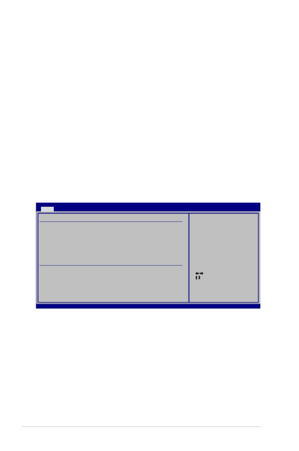
4-14 Chapter 4: BIOS setup
4.3.6 SATA 1~6
While entering Setup, the BIOS automatically detects the presence of SATA
devices. There is a separate sub-menu for each SATA device. Select a device item
then press <Enter> to display the IDE device information.
The BIOS automatically detects the values opposite the dimmed items (Device,
Vendor, Size, LBA Mode, Block Mode, PIO Mode, Async DMA, Ultra DMA, and
SMART monitoring). These values are not user-congurable. These items show
N/A if no SATA device is installed in the system.
LBA/Large Mode [Auto]
Enables or disables the LBA mode. Setting to [Auto] enables the LBA mode if the
device supports this mode, and if the device was not previously formatted with LBA
mode disabled.
Conguration options: [Disabled] [Auto]
Select Screen
Select Item
+- Change Option
F1 General Help
F10 Save and Exit
ESC Exit
v02.61 (C)Copyright 1985-2008, American Megatrends, Inc.
BIOS SETUP UTILITY
Main
Third IDE Master
Device : Hard Disk
Vendor : HDT722516DLA380
Size : 164.7GB
LBA Mode : Supported
Block Mode : 16Sectors
PIO Mode : 4
Async DMA : MultiWord DMA-2
Ultra DMA : Ultra DMA-6
SMART Monitoring: Supported
LBA/Large Mode [Auto]
Block(Multi-sector Transfer) M [Auto]
PIO Mode [Auto]
DMA Mode [Auto]
SMART Monitoring [Auto]
32Bit Data Transfer [Enabled]
Select the type of
device connected to
the system.
DMA Mode [Auto]
Selects the DMA mode.
Conguration options: [Auto] [SWDMA0] [SWDMA1] [SWDMA2] [MWDMA0]
[MWDMA1] [MWDMA2] [UDMA0] [UDMA1] [UDMA2] [UDMA3] [UDMA4] [UDMA5]
SMART Monitoring [Auto]
Allows you to enable or disable the HDD Self-Monitoring Analysis and Reporting
Technology (SMART) feature.
Conguration options: [Auto] [Disabled] [Enabled]
32Bit Data Transfer [Enabled]
Enables or disables 32-bit data transfer.
Conguration options: [Disabled] [Enabled]

ASUS P5N64 WS Professional 4-15
Block (Multi-Sector Transfer) [Auto]
Enables or disables data multi-sectors transfers. When set to [Auto], the data
transfer from and to the device occurs multiple sectors at a time if the device
supports multi-sector transfer feature. When set to [Disabled], the data transfer
from and to the device occurs one sector at a time.
Conguration options: [Disabled] [Auto]
PIO Mode [Auto]
Allows you to select the data transfer mode.
Conguration options: [Auto] [0] [1] [2] [3] [4]
DMA Mode [Auto]
Selects the DMA mode.
Conguration options: [Auto] [SWDMA0] [SWDMA1] [SWDMA2] [MWDMA0]
[MWDMA1] [MWDMA2] [UDMA0] [UDMA1] [UDMA2] [UDMA3] [UDMA4] [UDMA5]
SMART Monitoring [Auto]
Allows you to enable or disable the HDD Self-Monitoring Analysis and Reporting
Technology (SMART) feature.
Conguration options: [Auto] [Disabled] [Enabled]
32Bit Data Transfer [Enabled]
Enables or disables 32-bit data transfer.
Conguration options: [Disabled] [Enabled]
4.3.7 IDE Conguration
The items in this menu allow you to set or change the congurations for the IDE
devices installed in the system. Select an item then press <Enter> if you want to
congure the item.
IDE Conguration
nVidia RAID Function [Disabled]
Options
Disabled
Enabled
nVidia RAID Function [Disabled]
Allows you to enable or disable the NVIDIA RAID function.
Conguration options: [Disabled] [Enabled]

4-16 Chapter 4: BIOS setup
SATA1/2/3/4/5/6 [Disabled]
This item appears only when you set the item to [Enabled] nVidia RAID Function
and allows you to assign the SATA ports used for creating RAID sets.
Conguration options: [Disabled] [Enabled]
4.3.8 System Information
This menu gives you an overview of the general system specications. The BIOS
automatically detects the items in this menu.
AMIBIOS
Displays the auto-detected BIOS information.
Processor
Displays the auto-detected CPU specication.
System Memory
Displays the auto-detected system memory.
Select Screen
Select Item
F1 General Help
F10 Save and Exit
ESC Exit
v02.61 (C)Copyright 1985-2008, American Megatrends, Inc.
BIOS SETUP UTILITY
Main
AMIBIOS
Version : 0136
Build Date : 03/19/08
Processor
Type : Intel(R) Core(TM)2 Duo CPU @ 3.00GHz
Speed : 3000 MHz
Count : 2
System Memory
Available : 1024 MB

ASUS P5N64 WS Professional 4-17
4.4 Ai Tweaker menu
The Ai Tweaker menu items allow you to congure overclocking-related items.
Take caution when changing the settings of the Ai Tweaker menu items.
Incorrect eld values can cause the system to malfunction.
Current FSB/Memory Speed
Target Memory Speed
These items shows the current front side bus (FSB) and memory speed detected
by the BIOS and may vary depending on your settings of the System Clock Mode
item.
System Clock Mode [Auto]
Selects the system clock mode. Set this item to [Auto] to allow auto-adjustment
of FSB and memory clock. Set this item to [Linked] to allow FSB and memory to
overclock proportionally. Set this item to [Unlinked] to manually enter FSB and
memory clock.
Conguration options: [Auto] [Linked] [Unlinked]
FSB - Memory Ratio [Auto]
This sub-item appears only when you set the item to System Clock Mode
[Linked] and allows you to set the ratio between FSB and memory.
Conguration options: [Auto] [1:1] [5:4] [3:2] [Sync Mode]
Select Screen
Select Item
+- Change Option
F1 General Help
F10 Save and Exit
ESC Exit
v02.61 (C)Copyright 1985-2008, American Megatrends, Inc.
BIOS SETUP UTILITY
Main Advanced Power Boot Tools Exit Ai Tweaker
[Auto] Set FSB & Memor
clock automatically.
[Linked] Allows Memory
and FSB to overclock
proportionally.
[Manual] Enter FSB and
Memory clock manually.
Congure System Performance Settings
Current FSB Speed 1333 MHz
Current Memory Speed 800 MHz
Target Memory Speed 800 Mhz
System Clock Mode [Auto]
PCIE Frequency (MHz) [100]
Current CAS-RCD-RP-RAS-CMD 6-6-6-15-1T
Current RRd-RC-WR-WTR-REF 4-21-7-13-7.6uS
Memory Timings [Auto]
CPU Spread Spectrum [Auto]
NB PCIE Spread Spectrum [Auto]
SB PCIE Spread Spectrum [Auto]
CPU Voltage [Auto]
FSB Termination Voltage [Auto]
DRAM Voltage [Auto]
NB Voltage [Auto]
Scroll down to display the following items:
v02.61 (C)Copyright 1985-2008, American Megatrends, Inc.
SB Voltage [Auto]
SB 1.5VSB Voltage [Auto]
CPU GTL Voltage Reference [Auto]
The default values of the following items vary depending on the CPU and
memory modules you install on the motherboard.
4-18 Chapter 4: BIOS setup
FSB/CPU External Frequency Synchronization
Front Side Bus FSB 1600 FSB 1333 FSB 1066 FSB 800
CPU External Frequency 400 MHz 333 MHz 266 MHz 200 MHz
FSB Clock (Mhz) [1333]
This sub-item appears only when you set the item to System Clock Mode
[Linked] or [Unlinked] and allows you to manually enter the desired FSB clock
in MHz. Use the <+> and <-> keys to adjust the value. You can also type the
desired value using the numeric keypad. The values range from 400 to 2500.
Refer to the table below for the correct FSB and CPU external frequency
settings.
Memory Clock (Mhz) [800]
This sub-item appears only when you set the item to System Clock Mode
[Unlinked] and allows you to manually enter the desired memory clock in
MHz. Use the <+> and <-> keys to adjust the value. You can also type the
desired value using the numeric keypad. The values range from 400 to 3000.
PCIE Frequency (MHz) [100]
Allows you to set the PCI Express frequency. The values range from 100 to 200.
Current CAS-RCD-RP-RAS-CMD 6-6-6-15-1T
Current RRD-RC-WR-WTR-REF 4-21-7-13-7.6uS
These items shows the current memory timings detected by the BIOS and may
vary depending on your settings of the item.Memory Timings
Memory Timings [Auto]
Allows automatic or manual adjustments of the memory timings.
Conguration options: [Auto] [Manual]
The following sub-items appear only when you set the item Memory Timings
to [Manual].
tCL (CAS Latency) [Auto]
Conguration options: [Auto] [5] [6] - [17] [18]
tRCD [Auto]
Conguration options: [Auto] [1] [2] - [14] [15]
tRP [Auto]
Conguration options: [Auto] [1] [2] - [14] [15]
tRAS [Auto]
Conguration options: [Auto] [1] [2] - [62] [63]

ASUS P5N64 WS Professional 4-19
Command Per Clock (CMD) [Auto]
Conguration options: [Auto] [1T] [2T]
tRRD [Auto]
Conguration options: [Auto] [1] [2] - [14] [15]
tRC [Auto]
Conguration options: [Auto] [1] [2] - [62] [63]
tWR [Auto]
Conguration options: [Auto] [1] [2] - [14] [15]
tWTR [Auto]
Conguration options: [Auto] [1] [2] - [30] [31]
tREF [Auto]
Conguration options: [Auto] [7.8uS] [3.9uS]
tFAW [Auto]
Conguration options: [Auto] [1] [2] - [62] [63]
CPU Spread Spectrum [Auto]
Set to [Disabled] to enhance CPU overclocking ability or [Auto] for EMI control.
Conguration options: [Disabled] [Auto]
NB/SB PCIE Spread Spectrum [Auto]
Set to [Disabled] to enhance PCIE overclocking ability or [Auto] for EMI control.
Conguration options: [Auto] [Disabled]
The following ve items are adjusted by typing the desired values using the
numeric keypad and press the <Enter> key. You can also use the <+> and <->
keys to adjust the value. To restore the default setting, type [auto] using the
keyboard and press the <Enter> key.
CPU Voltage [Auto]
Allows you to set the CPU VCore voltage. The values range from 0.85000V to
1.80000V with a 0.00625V interval.
Refer to the CPU documentation before setting the CPU Voltage. Setting a
high voltage may damage the CPU permanently, and setting a low voltage may
make the system unstable.
FSB Termination Voltage [Auto]
Allows you to set the front side bus termination voltage. The values range from
1.20V to 2.46V with a 0.02V interval.
The minimum and standard value becomes [1.10V] when you install a 45nm
CPU.

4-20 Chapter 4: BIOS setup
DRAM Voltage [Auto]
Allows you to set the DRAM voltage. The values range from 1.50V to 3.10V with a
0.02V interval.
NB Voltage [Auto]
Allows you to set the North Bridge voltage. The values range from 1.30V to 2.00V
with a 0.02V interval.
• Setting the FSB Termination Voltage DRAM Voltage NB Voltage, and
items to a high level may damage the chipset, memory module and CPU
permanently. Proceed with caution.
• Some values of the FSB Termination Voltage DRAM Voltage NB , and
Voltage items are labeled in different color, indicating the risk levels of high
voltage settings. Refer to the table below for details.
• The system may need better cooling system to work stably under high
voltage settings.
Blue Yellow Purple Red
FSB Termination
Voltage 1.20V~1.38V 1.40V~2.46V N/A N/A
DRAM Voltage 1.50V~1.68V 1.70V~1.90V 1.92V~2.10V 2.12V~3.10V
NB Voltage 1.30V~1.46V 1.48V~1.60V 1.62V~1.78V 1.80V~2.00V*
SB Voltage [Auto]
Allows you to set the South Bridge voltage. The values range from 1.50V to 1.84V
with a 0.15V interval.
SB 1.5VSB Voltage
Allows you to set the SB 1.5VSB Voltage.
Conguration options: [Auto] [1.50V] [1.60V] [1.70V] [1.80V]
CPU GTL Voltage Reference [Auto]
Allows you to set the CPU GTL voltage reference. Different ratio might enhance
CPU overclocking ability.
Conguration options: [Auto] [0.67x] [0.65x] [0.63x] [0.62x]

ASUS P5N64 WS Professional 4-21
4.5 Advanced menu
The Advanced menu items allow you to change the settings for the CPU and other
system devices.
Take caution when changing the settings of the Advanced menu items. Incorrect
eld values can cause the system to malfunction.
v02.61 (C)Copyright 1985-2008, American Megatrends, Inc.
BIOS SETUP UTILITY
Main Ai Tweaker Power Boot Tools ExitAdvanced
USB Conguration
CPU Conguration
Chipset
Onboard Devices Conguration
PCIPnP
Select Screen
Select Item
+- Change Field
Tab Select Field
F1 General Help
F10 Save and Exit
ESC Exit
Congure the USB
support.
The item shows auto-detected values. If no USB device USB Devices Enabled
is detected, the item shows .None
BIOS SETUP UTILITY
Advanced
USB Conguration
Module Version - 2.24.3-13.4
USB Devices Enabled:
1 Mouse
Legacy USB Support [Enabled]
USB 2.0 Controller Mode [HiSpeed]
BIOS EHCI Hand-off [Enabled]
Enables support for
legacy USB. AUTO
option disables
legacy support if
no USB device are
connected.
4.5.1 USB Conguration
The items in this menu allows you to change the USB-related features. Select an
item then press <Enter> to display the conguration options.
Legacy USB Support [Enabled]
Allows you to enable or disable support for legacy USB devices. Setting to [Auto]
allows the system to detect the presence of USB devices at startup. If detected,
the USB controller legacy mode is enabled. If no USB device is detected, the
legacy USB support is disabled.
Conguration options: [Disabled] [Enabled] [Auto]

4-22 Chapter 4: BIOS setup
USB 2.0 Controller Mode [HiSpeed]
Allows you to set the USB 2.0 controller mode to HiSpeed (480 Mbps) or
FullSpeed (12 Mbps). This item appears only when you set the Legacy USB
Support item to [Enabled] or [Auto].
Conguration options: [FullSpeed ] [HiSpeed ]
BIOS EHCI Hand-off [Enabled]
Allows you to enable support for operating systems without an EHCI hand-off
feature.
Conguration options: [Disabled] [Enabled]
4.5.2 CPU Conguration
The items in this menu show the CPU-related information that the BIOS
automatically detects.
Select Screen
Select Item
F1 General Help
F10 Save and Exit
ESC Exit
v02.61 (C)Copyright 1985-2008, American Megatrends, Inc.
Congure advanced CPU settings
Manufacturer:Intel
Brand String:Intel(R) Core(TM)2 Duo CPU @ 3.00GHz
Frequency :3.00GHz
FSB Speed :1333MHz
Cache L1 :64 KB
Cache L2 :4096 KB
CPUID :6F9
Ratio Status:Unlocked (Max:09.0, Min:06.0)
Ratio Actual Value :9
CPU Ratio Setting [Auto]
C1E Support [Enabled]
CPU TM Function [Enabled]
Vanderpool Technology [Enabled]
Execute Disable Bit [Enabled]
Max CPUID Value Limit [Disabled]
Intel(R) SpeedStep(TM) Tech. [Enabled]
Sets the ratio between
CPU Core Clock and the
FSB Frequency.
NOTE: If an invalid
ratio is set in CMOS
then actual and
setpoint values may
differ.
NOTE:
Please Key in ratio
numbers directly!
BIOS SETUP UTILITY
Advanced
CPU Ratio Setting [Auto]
This item allows you to set the ratio between CPU Core Clock and FSB Frequency.
The value is adjusted by typing the desired values using the numeric keypad and
press the <Enter> key. You can also use the <+> and <-> keys to adjust the value.
To restore the default setting, type [auto] using the keyboard and press the <Enter>
key. If an invalid ratio is set in CMOS, then actual and setpoint values may differ.
C1E Support [Enabled]
Allows you to enable or disable Enhanced Halt State support.
Conguration options: [Disabled] [Enabled]
CPU TM function [Enabled]
This function enables the overheated CPU to throttle the clock speed to cool down.
Conguration options: [Disabled] [Enabled]
ASUS P5N64 WS Professional 4-23
Vanderpool Technology [Enabled]
The Vanderpool Technology allows a hardware platform to run multiple operating
systems separately and simultaneously, enabling one system to virtually function
as several systems.
Conguration options: [Disabled] [Enabled]
Execute Disable Bit [Enabled]
Allows you to enable or disable the No-Execution Page Protection Technology.
Setting this item to [Disabled] forces the XD feature ag to always return to zero
(0).
Conguration options: [Disabled] [Enabled]
Max CPUID Value Limit [Disabled]
Setting this item to [Enabled] allows legacy operating systems to boot even without
support for CPUs with extended CPUID functions.
Conguration options: [Disabled] [Enabled]
The following item appears only when you set the item to CPU Ratio Setting
[Auto]
Intel(R) SpeedStep (TM) Tech. [Enabled]
When set to [Disabled], the CPU runs at its default speed. When set to [Enabled],
the CPU speed is controlled by the operating system.
Conguration options: [Enabled] [Disabled]
4.5.3 Chipset
The Chipset menu allows you to change the advanced chipset settings. Select an
item then press <Enter> to display the sub-menu.
Advanced Chipset Settings
Memory Remap Feature [Enabled]
Primary Graphics Adapter [PCI Express]
NVMM ROM Version :4.081.59
ENABLE: Allow
remapping of
overlapped PCI memory
above the total
physical memory.
DISABLE: Do not allow
remapping of memory.
BIOS SETUP UTILITY
Advanced
Memory Remap Feature [Enabled]
Allows you to enabled or disable the remapping of the overlapped PCI memory
above the total physical memory. Enable this option only when you install 64-bit
operating system.
Conguration options: [Disabled] [Enabled]

4-24 Chapter 4: BIOS setup
4.5.4 Onboard Devices Conguration
Select Screen
Select Item
+- Change Option
F1 General Help
F10 Save and Exit
ESC Exit
v02.61 (C)Copyright 1985-2008, American Megatrends, Inc.
Onboard Device Conguraiton
High Denition Audio [Enabled]
OnChip LAN1 [Auto]
OnChip LAN2 [Auto]
LAN Boot ROM [Disabled]
Marvell 6121/eSATA [Legacy Mode]
6121 Boot ROM [Enabled]
Marvell 6320/SAS [Enabled]
6320 Boot ROM [Enabled]
Onboard 1394 [Enabled]
Serial Port1 Address [3F8/IRQ4]
Enable or Disable
High Denition Audio
Controller
BIOS SETUP UTILITY
Advanced
High Denition Audio [Enabled]
Allows you to enable or disable the High Denition Audio.
Conguration options: [Enabled] [Disabled]
OnChip LAN1/2 [Auto]
Allows you to enable or disable the onboard LAN ports.
Conguration options: [Auto] [Disabled]
LAN Boot ROM [Disabled]
This item appears only when you enable one of the previous items.
Conguration options: [Disabled] [Enabled]
Marvell 6121/eSATA [Legacy Mode]
Set this item to [RAID Mode] to create a RAID set using the external SATA ports on
the back panel.
Conguration options: [Legacy Mode] [RAID Mode] [Disabled]
6121 Boot ROM [Enabled]
This item appears only when you set the previous item to [Legacy Mode] or
[RAID Mode].
Conguration options: [Disabled] [Enabled]
Marvell 6320/SAS [Enabled]
Allows you to enable or disable the onboard SAS ports labelled SAS1 and SAS2.
Conguration options: [Enabled] [Disabled]
Primary Graphics Adapter [PCI Express]
Allows you to decide which graphics controller to use as the primary boot device.
Conguration options: [PCI] [PCI Express]
ASUS P5N64 WS Professional 4-25
6320 Boot ROM [Enabled]
This item appears only when you set the previous item to [Enabled].
Conguration options: [Enabled] [Disabled]
Onboard 1394 [Enabled]
Allows you to enable or disable the onboard IEEE 1394 connectors.
Conguration options: [Enabled] [Disabled]
Serial Port1 Address [3F8/IRQ4]
Allows the BIOS to select the Serial Port1 base address.
Conguration options: [Disabled] [3F8/IRQ4] [2F8/IRQ3] [3E8/IRQ4] [2E8/IRQ3]
4.5.5 PCI PnP
The PCI PnP menu item allows you to change the advanced settings for PCI/PnP
devices.
Plug And Play O/S [No]
When set to [No], BIOS congures all the devices in the system. When set to
[Yes] and if you install a Plug and Play operating system, the operating system
congures the Plug and Play devices not required for boot.
Conguration options: [No] [Yes]
Advanced PCI/PnP Settings
WARNING: Setting wrong values in below sections
may cause system to malfunction.
Plug And Play O/S [No]
NO: lets the BIOS
congure all the
devices in the system.
YES: lets the
operating system
congure Plug and
Play (PnP) devices not
required for boot if
your system has a Plug
and Play operating
system.
BIOS SETUP UTILITY
Advanced

4-26 Chapter 4: BIOS setup
4.6 Power menu
The Power menu items allow you to change the settings for the Advanced
Power Management (APM). Select an item then press <Enter> to display the
conguration options.
4.6.1 Suspend Mode [Auto]
Allows you to select the Advanced Conguration and Power Interface (ACPI) state
to be used for system suspend.
Conguration options: [S1 (POS) Only] [S3 Only] [Auto]
4.6.2 Repost Video on S3 Resume [No]
Determines whether to invoke VGA BIOS POST on S3/STR resume.
Conguration options: [No] [Yes]
4.6.3 ACPI 2.0 Support [Disabled]
Allows you to add more tables for Advanced Conguration and Power Interface
(ACPI) 2.0 specications.
Conguration options: [Disabled] [Enabled]
4.6.4 ACPI APIC Support [Enabled]
Allows you to enable or disable the Advanced Conguration and Power Interface
(ACPI) support in the Advanced Programmable Interrupt Controller (APIC). When
set to Enabled, the ACPI APIC table pointer is included in the RSDT pointer list.
Conguration options: [Disabled] [Enabled]
Select Screen
Select Item
+- Change Option
F1 General Help
F10 Save and Exit
ESC Exit
v02.61 (C)Copyright 1985-2008, American Megatrends, Inc.
Suspend Mode [Auto]
Repost Video on S3 Resume [No]
ACPI 2.0 Support [Disabled]
ACPI APIC Support [Enabled]
APM Conguration
Hardware Monitor
Select the ACPI state
used for System
Suspend.
BIOS SETUP UTILITY
Main Ai Tweaker Advanced Boot Tools ExitPower

ASUS P5N64 WS Professional 4-27
4.6.5 APM Conguration
Restore On AC Power Loss [Power Off]
When set to Power Off, the system goes into off state after an AC power loss.
When set to Power On, the system goes on after an AC power loss. When set to
Last State, the system goes into either off or on state, whatever the system state
was before the AC power loss.
Conguration options: [Power Off] [Power On] [Last State]
Power On By PCI Devices [Disabled]
Allows you to enable or disable the PME to wake up from S5 by PCI devices.
Conguration options: [Disabled] [Enabled]
Power On By PCIE Devices [Disabled]
Allows you to enable or disable the PCIE devices to generate a wake event.
Conguration options: [Disabled] [Enabled]
Power On By LAN(PHY) [Disabled]
Allows you to enable or disable the LAN(MAC) devices to generate a wake event.
Conguration options: [Disabled] [Enabled]
Power On By External Modems [Disabled]
This allows either settings of [Enabled] or [Disabled] for powering up the computer
when the external modem receives a call while the computer is in Soft-off mode.
Conguration options: [Disabled] [Enabled]
The computer cannot receive or transmit data until the computer and
applications are fully running. Thus, connection cannot be made on the rst
try. Turning an external modem off and then back on while the computer is off
causes an initialization string that turns the system power on.
Select Screen
Select Item
+- Change Option
F1 General Help
F10 Save and Exit
ESC Exit
v02.61 (C)Copyright 1985-2008, American Megatrends, Inc.
APM Conguration
Restore on AC Power Loss [Power Off]
Power On By PCI Devices [Disabled]
Power On By PCIE Devices [Disabled]
Power On By LAN(PHY) [Disabled]
Power On By External Modems [Disabled]
Power On By PS/2 Keyboard [Disabled]
Power On By RTC Alarm [Disabled]
<Enter> to select
whether or not to
restart the system
after AC power loss.
BIOS SETUP UTILITY
Power
4-28 Chapter 4: BIOS setup
Power On By PS/2 Keyboard [Disabled]
Allows you to enable or disable the Power On by PS/2 keyboard function. This
feature requires an ATX power supply that provides at least 1A on the +5VSB lead.
Conguration options: [Disabled] [Enabled]
Power On By RTC Alarm [Disabled]
Allows you to enable or disable RTC to generate a wake event. When this item is
set to Enabled, the items RTC Alarm Date System Time and will become user-
congurable with set values.
Conguration options: [Disabled] [Enabled]
v02.61 (C)Copyright 1985-2006, American Megatrends, Inc.
Select Screen
Select Item
+- Change Field
F1 General Help
F10 Save and Exit
ESC Exit
CPU Temperature
v02.61 (C)Copyright 1985-2008, American Megatrends, Inc.
BIOS SETUP UTILITY
Power
Hardware Monitor
CPU Temperature [39ºC/102ºF]
MB Temperature [36ºC/96.5ºF]
CPU Voltage [ 1.288V]
3.3V Voltage [ 3.296V]
5V Voltage [ 5.094V]
12V Voltage [11.616V]
CPU Fan Speed [3013RPM]
Chassis Fan 1 Speed [N/A]
Chassis Fan 2 Speed [N/A]
Chassis Fan 3 Speed [N/A][N/A]
Power Fan Speed [N/A][N/A]
CPU Q-Fan Function [Disabled]
Chassis Q-Fan Function [Disabled]
4.6.6 Hardware Monitor
CPU/MB Temperature [xxxºC/xxxºF]
The onboard hardware monitor automatically detects and displays the motherboard
and CPU temperatures. Select [Ignored] if you do not wish to display the detected
temperatures.
CPU Voltage, 3.3V Voltage, 5V Voltage, 12V Voltage
The onboard hardware monitor automatically detects the voltage output through
the onboard voltage regulators. Select [Ignored] if you do not want to detect this
item.
CPU Fan / Chassis Fan 1 / Chassis Fan 2 / Chassis Fan 3 / Power Fan
Speed [xxxxRPM] or [Ignored]
The onboard hardware monitor automatically detects and displays the CPU fan,
chassis fan(s), and power fan speed in rotations per minute (RPM). If the fan is not
connected to the motherboard, the eld shows [N/A].

ASUS P5N64 WS Professional 4-29
CPU Q-Fan Function [Disabled]
Allows you to enable or disable the CPU Q-Fan function.
Conguration options: [Disabled] [Enabled]
Smart Fan Mode [Optimal]
This item appears only when you enable the CPU Q-Fan Function item and allows
you to set the appropriate performance level of the CPU Q-Fan. When set to
[Optimal], the CPU fan automatically adjusts depending on the CPU temperature.
Set this item to [Silent] to minimize fan speed for quiet CPU fan operation, or
[Performance] to achieve maximum CPU fan speed.
Conguration options: [Performance] [Optimal] [Silent]
Chassis Q-Fan Function [Disabled]
Allows you to enable or disable the chassis Q-Fan function.
Conguration options: [Disabled] [Enabled]
The Chassis Q-Fan Start Volgate Chassis Q-Fan Start Speed Temp and
items appear only when you enable the feature.Chassis Q-Fan Function
Chassis Q-Fan Start Voltage [5.0V]
Allows you to set the minimum voltage requirement to start chassis fan speed
auto-adjustment.
Conguration options: [4.0V] [4.5V] [5.0V] [5.5V] [6.0V]
Chassis Q-Fan Start Speed Temp [25°C]
Allows you to set a minimum temperature to start chassis fan speed auto-
adjustment.
Conguration optinos: [25ºC] [26ºC] - [74ºC] [75ºC]

4-30 Chapter 4: BIOS setup
4.7 Boot menu
The Boot menu items allow you to change the system boot options. Select an item
then press <Enter> to display the sub-menu.
Select Screen
Select Item
Enter Go to Sub Screen
F1 General Help
F10 Save and Exit
ESC Exit
v02.61 (C)Copyright 1985-2008, American Megatrends, Inc.
Boot Device Priority
Boot Settings Conguration
Security
Species the Boot
Device Priority
sequence.
A virtual oppy disk
drive (Floppy Drive B:
) may appear when you
set the CD-ROM drive
as the rst boot
device.
4.7.1 Boot Device Priority
1st ~ xxth Boot Device [xxx Drive]
These items specify the boot device priority sequence from the available devices.
The number of device items that appears on the screen depends on the number of
devices installed in the system.
Conguration options: [1st FLOPPY DRIVE] [Hard Drive] [ATAPI CD-ROM]
[Disabled]
Select Screen
Select Item
+- Change Option
F1 General Help
F10 Save and Exit
ESC Exit
v02.61 (C)Copyright 1985-2008, American Megatrends, Inc.
Boot Device Priority
1st Boot Device [1st FLOPPY DRIVE]
2nd Boot Device [Hard Drive]
3rd Boot Device [ATAPI CD-ROM]
Species the boot
sequence from the
availabe devices.
A device enclosed in
parenthesis has been
disabled in the
corresponding type
menu.
BIOS SETUP UTILITY
Main Ai Tweaker Advanced Power Tools ExitBoot
BIOS SETUP UTILITY
Boot
ASUS P5N64 WS Professional 4-31
4.7.2 Boot Settings Conguration
Quick Boot [Enabled]
Enabling this item allows the BIOS to skip some power on self tests (POST) while
booting to decrease the time needed to boot the system. When set to [Disabled],
BIOS performs all the POST items.
Conguration options: [Disabled] [Enabled]
Full Screen Logo [Enabled]
This allows you to enable or disable the full screen logo display feature.
Conguration options: [Disabled] [Enabled]
Set this item to [Enabled] to use the ASUS MyLogo2™ feature.
AddOn ROM Display Mode [Force BIOS]
Sets the display mode for option ROM.
Conguration options: [Force BIOS] [Keep Current]
Bootup Num-Lock [On]
Allows you to select the power-on state for the NumLock.
Conguration options: [Off] [On]
Wait for ‘F1’ If Error [Enabled]
When set to Enabled, the system waits for the F1 key to be pressed when error
occurs. Conguration options: [Disabled] [Enabled]
Hit ‘DEL’ Message Display [Enabled]
When set to Enabled, the system displays the message “Press DEL to run Setup”
during POST. Conguration options: [Disabled] [Enabled]
Interrupt 19 Capture [Disabled]
When set to [Enabled], this function allows the option ROMs to trap Interrupt 19.
Conguration options: [Disabled] [Enabled]
Select Screen
Select Item
+- Change Option
F1 General Help
F10 Save and Exit
ESC Exit
v02.61 (C)Copyright 1985-2008, American Megatrends, Inc.
Boot Settings Conguration
Quick Boot [Enabled]
Full Screen Logo [Enabled]
AddOn ROM Display Mode [Force BIOS]
Bootup Num-Lock [On]
Wait for ‘F1’ If Error [Enabled]
Hit ‘DEL’ Message Display [Enabled]
Interrupt 19 Capture [Disabled]
Allows BIOS to skip
certain tests while
booting. This will
decrease the time
needed to boot the
system.
BIOS SETUP UTILITY
Boot

4-32 Chapter 4: BIOS setup
Change Supervisor Password
Select this item to set or change the supervisor password. The Supervisor
Password item on top of the screen shows the default Not Installed. After you set a
password, this item shows Installed.
To set a Supervisor Password:
1. Select the Change Supervisor Password item and press <Enter>.
2. From the password box, type a password composed of at least six letters
and/or numbers, then press <Enter>.
3. Conrm the password when prompted.
The message “Password Installed” appears after you successfully set your
password.
To change the supervisor password, follow the same steps as in setting a user
password.
To clear the supervisor password, select the Change Supervisor Password then
press <Enter>. The message “Password Uninstalled” appears.
If you forget your BIOS password, you can clear it by erasing the CMOS Real
Time Clock (RTC) RAM. See section for information on how to 2.6 Jumper
erase the RTC RAM.
After you have set a supervisor password, the other items appear to allow you to
change other security settings.
4.7.3 Security
The Security menu items allow you to change the system security settings. Select
an item then press <Enter> to display the conguration options.
Select Screen
Select Item
Enter Change
F1 General Help
F10 Save and Exit
ESC Exit
v02.61 (C)Copyright 1985-2008, American Megatrends, Inc.
Security Settings
Supervisor Password :Not Installed
User Password :Not Installed
Change Supervisor Password
Change User Password
<Enter> to change
password.
<Enter> again to
disabled password.
BIOS SETUP UTILITY
Boot

ASUS P5N64 WS Professional 4-33
User Access Level [Full Access]
This item allows you to select the access restriction to the Setup items.
Conguration options: [No Access] [View Only] [Limited] [Full Access]
No Access prevents user access to the Setup utility.
View Only allows access but does not allow change to any eld.
Limited allows changes only to selected elds, such as Date and Time.
Full Access allows viewing and changing all the elds in the Setup utility.
Change User Password
Select this item to set or change the user password. The User Password item on
top of the screen shows the default Not Installed. After you set a password, this
item shows Installed.
To set a User Password:
1. Select the Change User Password item and press <Enter>.
2. On the password box that appears, type a password composed of at least six
letters and/or numbers, then press <Enter>.
3. Conrm the password when prompted.
The message “Password Installed” appears after you set your password
successfully.
To change the user password, follow the same steps as in setting a user password.
Clear User Password
Select this item to clear the user password.
Password Check [Setup]
When set to [Setup], BIOS checks for user password when accessing the Setup
utility. When set to [Always], BIOS checks for user password both when accessing
Setup and booting the system. Conguration options: [Setup] [Always]
Select Screen
Select Item
Enter Change
F1 General Help
F10 Save and Exit
ESC Exit
v02.61 (C)Copyright 1985-2008, American Megatrends, Inc.
<Enter> to change
password.
<Enter> again to
disabled password.
BIOS SETUP UTILITY
Boot
Security Settings
Supervisor Password :Installed
User Password :Installed
Change Supervisor Password
User Access Level [Full Access]
Change User Password
Clear User Password
Password Check [Setup]

4-34 Chapter 4: BIOS setup
4.8 Tools menu
The Tools menu items allow you to congure options for special functions. Select
an item then press <Enter> to display the sub-menu.
4.8.1 ASUS EZ Flash 2
Allows you to run ASUS EZ Flash 2. When you press <Enter>, a conrmation
message appears. Use the left/right arrow key to select between [Ok] or [Cancel],
then press <Enter> to conrm your choice. Please see section 4.1.3 ASUS EZ
Flash 2 utility for details.
ASUSTek EZ Flash 2 BIOS ROM Utility V3.24
Current ROM Update ROM
A:
C:
Note
[Enter] Select or Load [B] Backup [ESC] Exit
[Tab] Switch [Up/Down/Home/End] Move
FLASH TYPE: SST 49LF080/A LPC
PATH: A:\
BOARD: P5N64-WS PRO
VER: 0136
DATE: 03/19/2008
BOARD: Unknown
VER: Unknown
DATE: Unknown
Select Screen
Select Item
+- Change Field
Enter Go to Sub Screen
F1 General Help
F10 Save and Exit
ESC Exit
v02.61 (C)Copyright 1985-2008, American Megatrends, Inc.
ASUS EZ Flash 2
Express Gate [Enabled]
Reset User Data [10]
Enter OS Timer [10 Seconds]
ASUS O.C. Prole
AI NET 2
Press ENTER to run
the utility to select
and update BIOS.
This utility doesn't
support :
1.NTFS format
BIOS SETUP UTILITY
Main Ai Tweaker Advanced Power Boot ExitTools

ASUS P5N64 WS Professional 4-35
4.8.2 Express Gate [Enabled]
Allows you to enable or disable the ASUS Express Gate feature. The ASUS
Express Gate feature is a unique instant-on environment that provides quick
access to the Internet browser and Skype. Refer to section 5.3.11 for details.
Conguration options: [Enabled] [Disabled]
Reset User Data [No]
Allows you to clear Express Gate’s user data.
Conguration options: [No] [Reset]
When setting this item to [Reset], make sure to save the setting to the BIOS
so that the user data will be cleared the next time you enter the Express
Gate. User data includes the Express Gate’s settings as well as any personal
information stored by the web browser (bookmarks, cookies, browsing
history, etc.). This is useful in the rare case where corrupt settings prevent
the Express Gate environment from launching properly.
The rst time wizard will run again when you enter the Express Gate
environment after clearing its settings.
Enter OS Timer [10 Seconds]
Sets the amount of time the system waits at the Express Gate’s rst screen
before defaulting to starting Windows or other installed OS. Set this item to
[Prompt User] to wait indenitely at the rst screen for user action.
Conguration options: [Prompt User] [1 Second] [3 Seconds] [5 Seconds] [10
Seconds] [15 Seconds] [20 Seconds] [30 seconds]
4.8.3 ASUS O.C. Prole
This item allows you to store or load multiple BIOS settings.
Select Screen
Select Item
Enter Go to Sub Screen
F1 General Help
F10 Save and Exit
ESC Exit
v02.61 (C)Copyright 1985-2008, American Megatrends, Inc.
O.C. PROFILE Conguration
O.C. Prole 1 Status :Not Installed
O.C. Prole 2 Status :Not Installed
Save to Prole 1
Load from Prole 1
Save to Prole 2
Load from Prole 2
Start O.C. Prole
Save to Prole 1
BIOS SETUP UTILITY
Tools

4-36 Chapter 4: BIOS setup
Save to Proe 1/2
Allows you to save the current BIOS le to the BIOS Flash. Press <Enter> to save
the le.
Load from Prole 1/2
Allows you to load the previous BIOS settings saved in the BIOS Flash. Press
<Enter> to load the le.
Start O.C. Prole
Allows you to run the utility to save and load CMOS. Press <Enter> to run the
utility.
ASUSTek O.C. Prole Utility V1.24
Current CMOS Restore CMOS
A:
C:
Note
[Enter] Select or Load [B] Backup [ESC] Exit
[Tab] Switch [Up/Down/Home/End] Move
PATH: A:\
BOARD: P5N64-WS PRO
VER: 0136
DATE: 03/19/2008
BOARD: Unknown
VER: Unknown
DATE: Unknown
• This function can support devices such as a USB ash disk or a oppy disk
with FAT 32/16 format and single partition only.
• DO NOT shut down or reset the system while updating the BIOS to prevent
the system boot failure!

ASUS P5N64 WS Professional 4-37
Marvell Phy POST Check LAN cab [Disabled]
Allows you to enable or disable LAN cable check during POST. When enabled, the
menu reports the cable faults or shorts, and displays the point (length) where the
faults or shorts are detected.
Conguration options: [Disabled] [Enabled]
4.8.4 Ai Net 2
This menu displays the status of the Local Area Network (LAN) cables connected
to the LAN (RJ-45) ports.
Select Screen
Select Item
+- Change Option
F1 General Help
F10 Save and Exit
ESC Exit
v02.61 (C)Copyright 1985-2007, American Megatrends, Inc.
BIOS SETUP UTILITY
Tools
AI NET 2
Pair Status Length
1-2 N/A Marvell Phy 0
3-6 N/A
4-5 N/A
7-8 N/A
1-2 N/A Marvell Phy 1
3-6 N/A
4-5 N/A
7-8 N/A
Marvell Phy POST Check LAN cab [Disabled]
Marvell Phy Check
LAN cable during
POST.
4-38 Chapter 4: BIOS setup
4.9 Exit menu
Pressing <Esc> does not immediately exit this menu. Select one of the options
from this menu or <F10> from the legend bar to exit.
The Exit menu items allow you to load the optimal or failsafe default values for the
BIOS items, and save or discard your changes to the BIOS items.
Exit & Save Changes
Once you are nished making your selections, choose this option from the Exit
menu to ensure the values you selected are saved to the CMOS RAM. An onboard
backup battery sustains the CMOS RAM so it stays on even when the PC is turned
off. When you select this option, a conrmation window appears. Select YES to
save changes and exit.
If you attempt to exit the Setup program without saving your changes, the
program prompts you with a message asking if you want to save your changes
before exiting. Press <Enter> to save the changes while exiting.
Exit & Discard Changes
Select this option only if you do not want to save the changes that you made to
the Setup program. If you made changes to elds other than System Date, System
Time, and Password, the BIOS asks for a conrmation before exiting.
Discard Changes
This option allows you to discard the selections you made and restore the
previously saved values. After selecting this option, a conrmation appears. Select
YES to discard any changes and load the previously saved values.
Load Setup Defaults
This option allows you to load the default values for each of the parameters on the
Setup menus. When you select this option or if you press <F5>, a conrmation
window appears. Select YES to load default values. Select Exit & Save Changes
or make other changes before saving the values to the non-volatile RAM.
Select Screen
Select Item
Enter Go to Sub Screen
F1 General Help
F10 Save and Exit
ESC Exit
v02.61 (C)Copyright 1985-2008, American Megatrends, Inc.
BIOS SETUP UTILITY
Main Ai Tweaker Advanced Power Boot Tools Exit
Exit Options
Exit & Save Changes
Exit & Discard Changes
Discard Changes
Load Setup Defaults
Exit system setup
after saving the
changes.
F10 key can be used
for this operation.

5
Chapter 5: Software
support
This chapter describes the contents of
the support DVD that comes with the
motherboard package.

ASUS P5N64 WS Professional
Chapter summary
5
5.1 Installing an operating system ................................................... 5-1
5.2 Support DVD information ............................................................ 5-1
5.3 Software information ................................................................... 5-9
5.4 RAID congurations .................................................................. 5-40
5.5 Creating a RAID driver disk ....................................................... 5-63

ASUS P5N64 WS Professional 5-1
If Autorun is NOT enabled in your computer, browse the contents of the support
DVD to locate the le ASSETUP.EXE from the BIN folder. Double-click the
ASSETUP.EXE to run the DVD.
5.1 Installing an operating system
This motherboard supports Windows ® XP/64-bit XP/Vista/64-bit Vista operating
systems (OS). Always install the latest OS version and corresponding updates to
maximize the features of your hardware.
5.2 Support DVD information
The support DVD that came with the motherboard package contains the drivers,
software applications, and utilities that you can install to avail all motherboard
features.
5.2.1 Running the support DVD
Place the support DVD to the optical drive. The DVD automatically displays the
Drivers menu if Autorun is enabled in your computer.
• Motherboard settings and hardware options vary. Use the setup
procedures presented in this chapter for reference only. Refer to your OS
documentation for detailed information.
• Make sure that you install Windows ® XP Service Pack 2 or later versions
before installing the drivers for better compatibility and system stability.
The contents of the support DVD are subject to change at any time without
notice. Visit the ASUS website(www.asus.com) for updates.
Click an item to install
Click an icon to
display support
DVD/motherboard
information

5-2 Chapter 5: Software support
5.2.2 Drivers menu
The drivers menu shows the available device drivers if the system detects installed
devices. Install the necessary drivers to activate the devices.
ASUS InstAll - Installation Wizard for Drivers
Installs all of the drivers through the Installation Wizard.
NVIDIA Chipset Driver Program
Installs the NVIDIA ® chipset driver program.
SoundMAX ADI Audio Driver
Installs the ADI 1988B audio driver and application.
Marvell 61xx SATA RAID Controller Driver
Installs the Marvell 61xx SATA RAID controller driver and the Marvell Tray RAID
Utility.
Marvell 64xx/63xx SAS Controller Driver
Installs the Marvell 64xx/63xx SAS controller driver.
ASUS WiFi-AP @n
Installs the ASUS WiFi-AP @n driver.

ASUS P5N64 WS Professional 5-3
5.2.3 Utilities menu
The Utilities menu shows the applications and other software that the motherboard
supports.
ASUS InstAll - Installation Wizard for Utilities
Installs all of the utilities through the Installation Wizard.
ASUS Update
Allows you to download the latest version of the BIOS from the ASUS website.
Before using the ASUS Update, make sure that you have an Internet connection
so you can connect to the ASUS website.
Click to display the
next page
Click to return to the
previous page

5-4 Chapter 5: Software support
ASUS PC Probe II
This smart utility monitors the fan speed, CPU temperature, and system voltages,
and alerts you of any detected problems. This utility helps you keep your computer
in healthy operating condition.
ASUS AI Suite
Installs the ASUS AI Suite.
ASUS Express Gate Updater
Installs the ASUS Express Gate™ update application.
Adobe Reader V7.0
Installs the Adobe ® Reader that allows you to open, view, and print documents in
Portable Document Format (PDF).
Anti-Virus Utility
The anti-virus application detects and protects your computer from viruses that
destroys data.
Anti-Virus Utility Download
Allows you to update your anti-virus utility version from the Internet.
InterVideo WinDVD 8 TrialDVD 8 Trial
Installs the InterVideo DVD WinDVD 8 trial version.
Ulead PhotoImpact 12 SE
Installs the PhotoImpact image editing software.
CyberLink PowerBackup
Installs CyberLink PowerBackup to back up and restore your data easily.
Corel Snapre Plus SE
Installs Corel Snapre Plus SE.
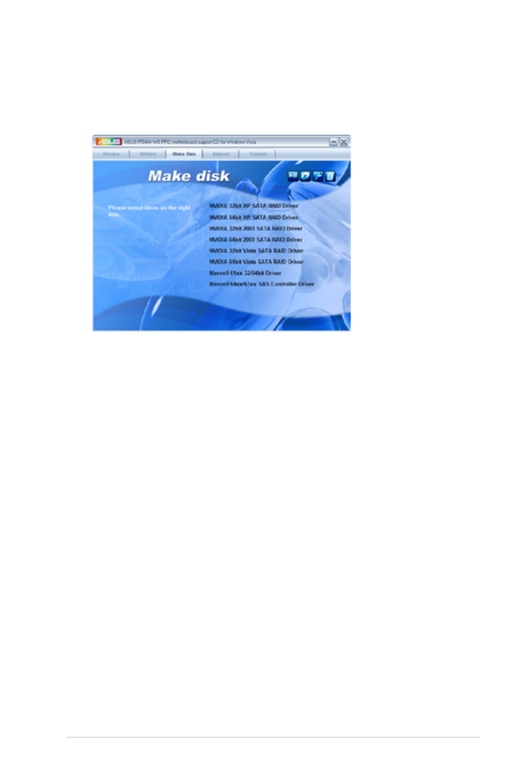
ASUS P5N64 WS Professional 5-5
5.2.4 Make Disk menu
The Make Disk menu contains items to create NVIDIA ® nForcenForce ® 790i Ultra SLI™
SATA RAID driver disk / Marvell ® 61xx eSATA driver disk / Marvell ® 63xx SAS
controller driver disk.
NVIDIA 32/64bit XP SATA RAID Driver
Allows you to create an NVIDIA ® nForce ® 790i Ultra SLI™ SATA RAID driver disk™ SATA RAID driver disk SATA RAID driver disk
for a 32/64-bit Windows ® XP OS.
NVIDIA 32/64bit 2003 SATA RAID Driver
Allows you to create an NVIDIA ® nForce ® 790i Ultra SLI™ SATA RAID driver disk™ SATA RAID driver disk SATA RAID driver disk
for a 32/64-bit Windows ® Server 2003 OS.
NVIDIA 32/64bit Vista SATA RAID Driver
Allows you to create an NVIDIA ® nForce ® 790i Ultra SLI™ SATA RAID driver disk™ SATA RAID driver disk SATA RAID driver disk
for a 32/64-bit Windows ® Vista OS.
Marvell 61xx 32/64bit Driver
Allows you to create a Marvell ® 61xx eSATA RAID driver disk for a 32/64-bit
system.
Marvell 64xx/63xx SAS Controller Driver
Allows you to create a Marvell ® 63xx SAS controller driver disk for a 32/64-bit
system.

5-6 Chapter 5: Software support
5.2.5 Manual menu
The Manual menu contains a list of supplementary user manuals. Click an item to
open the folder of the user manual.
Most user manual les are in Portable Document Format (PDF). Install the
Adobe ® Acrobat ® Reader from the Utilities tab before opening a user manual
le.
5.2.6 ASUS Contact information
Click the Contact tab to display the ASUS contact information. You can also nd
this information on the inside front cover of this user guide.

ASUS P5N64 WS Professional 5-7
5.2.7 Other information
The icons on the top right corner of the screen give additional information on the
motherboard and the contents of the support DVD. Click an icon to display the
specied information.
Motherboard Info
Displays the general specications of the motherboard.
Browse this DVD
Displays the support DVD contents in graphical format.
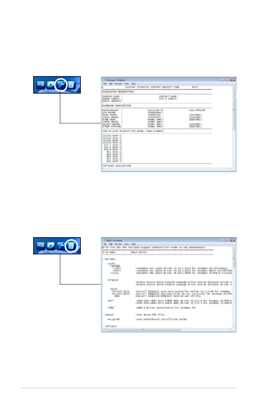
5-8 Chapter 5: Software support
Technical support Form
Displays the ASUS Technical Support Request Form that you have to ll out when
requesting technical support.
File list
Displays the contents of the support DVD and a brief description of each in text
format.

ASUS P5N64 WS ProfessionalP5N64 WS Professional 5-9
5.3 Software information
Most of the applications in the Support DVD have wizards that will conveniently
guide you through the installation. View the online help or readme le that came
with the software application for more information.
5.3.1 ASUS MyLogo2™
The ASUS MyLogo2™ utility lets you customize the boot logo. The boot logo is the
image that appears on screen during the Power-On Self-Tests (POST). The ASUS
MyLogo2™ is automatically installed when you install the ASUS Update utility from
the Support DVD. See section for details.5.2.3 Utilities menu
To launch the ASUS MyLogo2™:
1. Launch the ASUS Update utility. Refer to section 4.1.1 ASUS Update utility
for details.
2. Select from the drop down menu, then click .Options Next
3. Check the option to replace system boot logo before Launch MyLogo
ashing BIOS, then click Next.
4. Select . Update BIOS Next from a le from the drop down menu, then click
5. When prompted, locate the new
BIOS le, then click Next. The ASUS
MyLogo window appears.
6. From the left window pane, select the
folder that contains the image you
intend to use as your boot logo.
• Before using the ASUS MyLogo2™, use the AFUDOS utility to make a copy
of your original BIOS le, or obtain the latest BIOS version from the ASUS
website. See section 4.1.4 AFUDOS utility.
• Make sure that the BIOS item Full Screen Logo is set to [Enabled] if
you wish to use ASUS MyLogo2. See section 4.7.2 Boot Settings
Conguration.
• You can create your own boot logo image in GIF or BMP le formats.
• The le size should be smaller than 150 K.
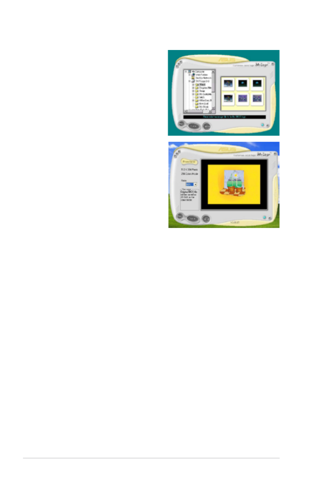
5-10 Chapter 5: Software support
9. When the screen returns to the ASUS Update utility, ash the original BIOS to
load the new boot logo.
10. After ashing the BIOS, restart the computer to display the new boot logo
during POST.
8. Adjust the boot image to your desired
size by selecting a value on the Ratio
box.
7. When the logo images appear on the
right window pane, select an image to
enlarge by clicking on it.

ASUS P5N64 WS ProfessionalP5N64 WS Professional 5-11
5.3.2 ASUS PC Probe II
PC Probe II is a utility that monitors the computer’s vital components, and detects
and alerts you of any problem with these components. PC Probe II senses fan
rotations, CPU temperature, and system voltages, among others. Because PC
Probe II is software-based, you can start monitoring your computer the moment
you turn it on. With this utility, you are assured that your computer is always at a
healthy operating condition.
Installing PC Probe II
To install PC Probe II on your computer:
1. Place the Support DVD to the optical drive. The Drivers installation tab
appears if your computer has an enabled Autorun feature.
If Autorun is not enabled in your computer, browse the contents of the Support
DVD to locate the setup.exe le from the ASUS PC Probe II folder. Double-click
the setup.exe le to start installation.
2. Click the Utilities tab, then click ASUS PC Probe II.
3. Follow the screen instructions to complete installation.
Launching PC Probe II
You can launch the PC Probe II right after installation or anytime from the
Windows ® desktop.
To launch the PC Probe II from the Windows ® desktop, click Start > All Programs
> ASUS > PC Probe II > PC Probe II v1.xx.xx. The PC Probe II main window
appears.
After launching the application, the PC Probe II icon appears in the Windows®
taskbar. Click this icon to close or restore the application.
Using PC Probe II
Main window
The PC Probe II main window allows you to view the current status of your
system and change the utility
conguration. By default, the main
window displays the Preference
section. You can close or restore
the Preference section by clicking
on the triangle on the main
window right handle.
Click to close the
Preference panel
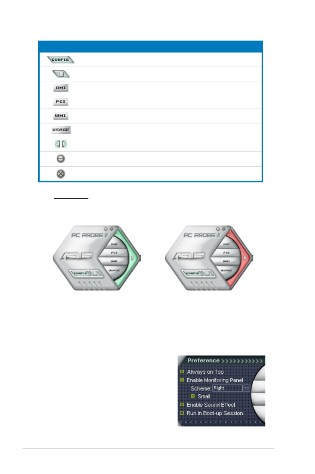
5-12 Chapter 5: Software support
Sensor alert
When a system sensor detects a problem, the main window right handle
turns red, as the illustrations below show.
When displayed, the monitor panel for that sensor also turns red. Refer to the
Monitor panels section for details.
Preference
You can customize the application
using the Preference section in the
main window. Click the box before each
preference to activate or deactivate.
Button Function
Opens the Conguration window
Opens the Report window
Opens the Desktop Management Interface window
Opens the Peripheral Component Interconnect window
Opens the Windows Management Instrumentation window
Opens the hard disk drive, memory, CPU usage window
Shows/Hides the Preference section
Minimizes the application
Closes the application

ASUS P5N64 WS ProfessionalP5N64 WS Professional 5-13
Changing the monitor panels position
To change the position of the monitor panels in the desktop,
click the arrow down button of the Scheme options, then select
another position from the list box. Click OK when nished.
Moving the monitor panels
All monitor panels move together using a magnetic effect. If
you want to detach a monitor panel from
the group, click the horseshoe magnet
icon. You can now move or reposition the
panel independently.
Hardware monitor panels
The hardware monitor panels display the current value of a system sensor such as
fan rotation, CPU temperature, and voltages.
The hardware monitor panels come in two display modes: hexagonal (large) and
rectangular (small). When you check the Enable Monitoring Panel option from the
Preference section, the monitor panels appear on your computer’s desktop.
Large display
Small display
Click to
increase
value
Click to
decrease
value
Adjusting the sensor threshold value
You can adjust the sensor threshold
value in the monitor panel by
clicking the or buttons. You can
also adjust the threshold values
using the Cong window.
You cannot adjust the sensor
threshold values in a small
monitoring panel.
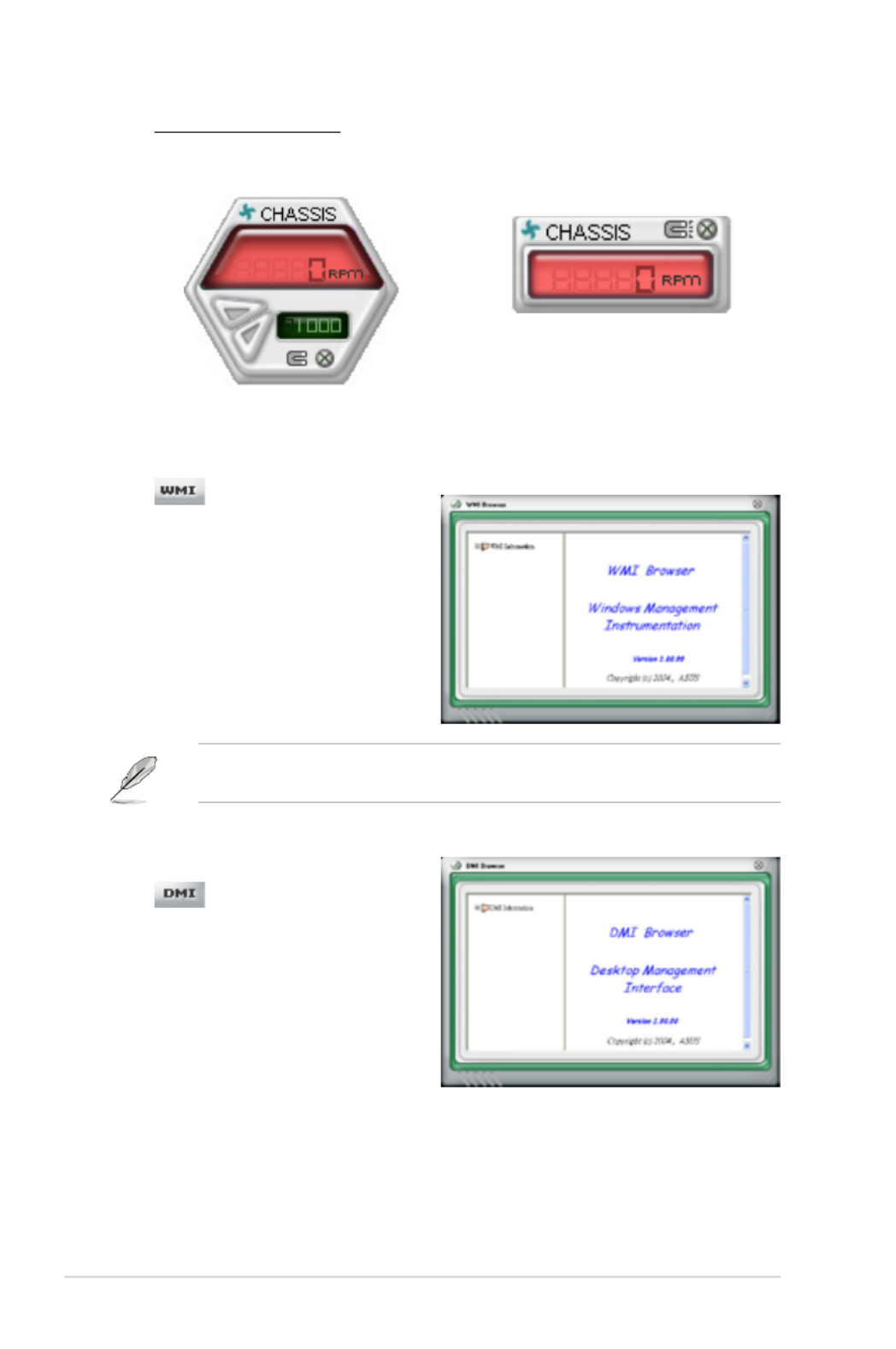
5-14 Chapter 5: Software support
Monitoring sensor alert
The monitor panel turns red when a component value exceeds or is lower
than the threshold value. Refer to the illustrations below.
Large display
Small display
WMI browser
Click to display the
WMI (Windows Management
Instrumentation) browser. This
browser displays various Windows®
management information. Click an
item from the left panel to display on
the right panel. Click the plus sign (+)
before WMI Information to display the
available information.
You can enlarge or reduce the browser size by dragging the bottom right corner
of the browser.
DMI browser
Click to display the DMI
(Desktop Management Interface)
browser. This browser displays various
desktop and system information.
Click the plus sign (+) before DMI
Information to display the available
information.

ASUS P5N64 WS ProfessionalP5N64 WS Professional 5-15
PCI browser
Click to display the PCI
(Peripheral Component Interconnect)
browser. This browser provides
information on the PCI devices installed
on your system. Click the plus sign
(+) before the PCI Information item to
display available information.
Usage
The Usage browser displays real-time information on the CPU, hard disk drive
space, and memory usage. Click to display the Usage browser.
CPU usage
The CPU tab displays real-
time CPU usage in line graph
representation. If the CPU has
an enabled Hyper-Threading,
two separate line graphs display
the operation of the two logical
processors.
Hard disk drive space usage
The Hard Disk tab displays the
used and available hard disk
drive space. The left panel of the
tab lists all logical drives. Click
a hard disk drive to display the
information on the right panel.
The pie chart at the bottom of
the window represents the used
(blue) and the available HDD

5-16 Chapter 5: Software support
Memory usage
The Memory tab shows both
used and available physical
memory. The pie chart at the
bottom of the window represents
the used (blue) and the available
physical memory.
Conguring PC Probe II
Click to view and adjust the sensor threshold values.
The Cong window has two tabs: Sensor/Threshold and Preference. The Sensor/
Threshold tab enables you to activate the sensors or to adjust the sensor threshold
values. The Preference tab allows you to customize sensor alerts, or change the
temperature scale.
Loads the default
threshold values for
each sensor
Applies your
changes
Cancels or
ignores your
changes
Loads your saved
conguration
Saves your
conguration

ASUS P5N64 WS ProfessionalP5N64 WS Professional 5-17
5.3.3 ASUS AI Suite
ASUS AI Suite allows you to launch AI Gear 3 +, AI Booster, AI Nap, and Q-Fan 2
utilities easily.
Install the ASUS EPU + AI Gear 3 Driver before the ASUS AI Suite utility.
Otherwise, ASUS AI Suite will not function properly.
Installing AI Suite
To install AI Suite on your computer:
1. Place the support DVD to the optical drive. The Drivers installation tab
appears if your computer has an enabled Autorun feature.
2. Click the Utilities tab, then click .AI Suite
3. Follow the screen instructions to complete installation.
Launching AI Suite
You can launch the AI Suite right after installation or anytime from the Windows ®
desktop.
To launch the AI Suite from the Windows ® desktop, click > >Start All Programs
ASUS AI Suite AI Suite v1.xx.xx> > . The AI Suite main window appears.
After launching the application, the AI Suite icon appears in the Windows ® taskbar.
Click this icon to close or restore the application.
Using AI Suite
Click the AI Gear 3 +, AI Nap, AI Booster, or Q-Fan 2 icon to launch the utility, or
click the Normal icon to restore the system to normal state.
Press to launch AI Gear 3 +
Press to launch AI Nap
Press to launch Q-Fan 2
Press to launch AI Booster
Press to restore to normal

5-18 Chapter 5: Software support
Other feature buttons
Click on right corner of the main window to open the monitor window.
Click on right corner of the expanded window to switch the temperature from
degrees Centigrade to degrees Fahrenheit.
Displays the CPU/
system temperature,
CPU/memory/PCIE
voltage, and CPU/
chassis fan speed
Displays the FSB/CPU
frequency
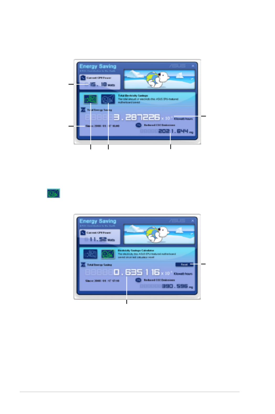
5-20 Chapter 5: Software support
Energy Saving Status
Displays the
current CPU
power
Displays the
time/date the
calculator
starts counting
Displays the
amount of
electricity saved
since the system
started up
Displays the amount
of CO2 that has been
reduced
Click to open the window. You may reset the Electricity Savings Calculator
time for the calculator to start counting.
Click to reset
the time the
calculator starts
Displays the electricity saved since
the time was reset
Click to switch to the
“Electricity Savings
Calculator” window
Click to switch to
the “Total Electricity
Savings” window

ASUS P5N64 WS ProfessionalP5N64 WS Professional 5-21
5.3.5 ASUS AI Nap
This feature allows you to minimize the power consumption of your computer
whenever you are away. Enable this feature for minimum power consumption and
a quieter system operation.
After installing AI Suite from the bundled Support DVD, you can launch the utility
by double-clicking the AI Suite icon on the Windows OS taskbar and click the AI
Nap button on the AI Suite main window.
Click Yes on the conrmation screen.
To exit AI Nap mode, press the system power or mouse button then click Yes on
the conrmation screen.
To switch the power button functions from AI Nap to shutting down, just right
click the icon on the OS taskbar, select and click AI Suite AI Nap Use power
button. Unclick the the item to switch the function back.
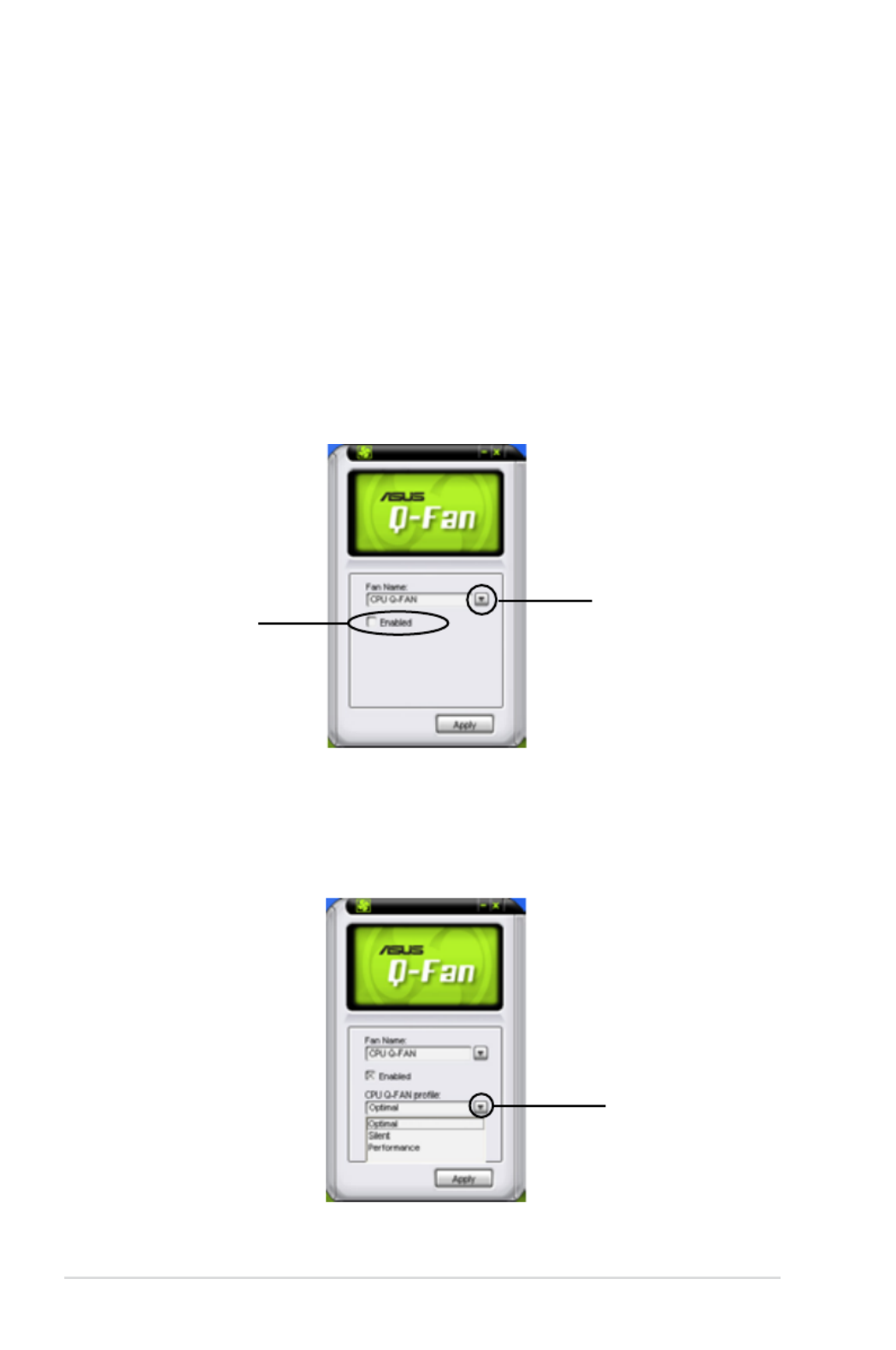
5-22 Chapter 5: Software support
5.3.6 ASUS Q-Fan 2
This ASUS Q-Fan 2 Control feature allows you to set the appropriate performance
level of the CPU Q-Fan 2 or the Chassis Q-Fan 2 for more efcient system
operation. After enabling the Q-Fan 2 function, the fans can be set to automatically
adjust depending on the temperature, to decrease fan speed, or to achieve the
maximum fan speed.
After installing AI Suite from the bundled Support DVD, you can launch the utility
by double-clicking the AI Suite icon on the Windows ® OS taskbar and click the Q-
Fan 2 button on the AI Suite main window.
Click the drop-down menu button and display the fan names. Select or CPU Q-Fan
CHASSIS Q-Fan Enabled . Click the box to activate this function.
drop-down list
button
Enable Q-Fan 2
box
Prole list appears after clicking the box. Click the drop-down list Enabled
button and select a prole. Optimal mode makes the fans adjust speed with
the temperature; mode minimizes fan speed for quiet fan operation; Silent
Performance mode boosts the fan to achieve maximal fan speed for the best
cooling effect.
click to display the drop-
down list and select a
Q-Fan 2 mode
Click at the bottom to save the setup.Apply
Produktspecifikationer
| Varumärke: | Asus |
| Kategori: | Server |
| Modell: | P5N64 WS Professional |
Behöver du hjälp?
Om du behöver hjälp med Asus P5N64 WS Professional ställ en fråga nedan och andra användare kommer att svara dig
Server Asus Manualer

2 April 2025
9 December 2024
7 Oktober 2024
3 Oktober 2024
21 September 2024
19 September 2024
16 September 2024
16 September 2024
8 September 2024
5 September 2024
Server Manualer
- Server Sony
- Server HP
- Server Medion
- Server Toshiba
- Server Abus
- Server Acer
- Server Allnet
- Server Apc
- Server Acti
- Server Hikvision
- Server SilverStone
- Server Megasat
- Server Maxdata
- Server Lenovo
- Server Black Box
- Server Tripp Lite
- Server Axis
- Server Gigabyte
- Server Nec
- Server Technics
- Server Cisco
- Server AVerMedia
- Server Matrox
- Server Flir
- Server Fujitsu
- Server Digitus
- Server Kathrein
- Server Asrock
- Server Linksys
- Server Buffalo
- Server Supermicro
- Server GeoVision
- Server Netgear
- Server LevelOne
- Server QNAP
- Server LaCie
- Server Dell
- Server Valcom
- Server Asustor
- Server Planet
- Server ZyXEL
- Server Western Digital
- Server Intel
- Server Fantec
- Server MSI
- Server D-Link
- Server Freecom
- Server Eaton
- Server Seagate
- Server Iomega
- Server Synology
- Server Elac
- Server Trendnet
- Server Blackmagic Design
- Server ATen
- Server Veritas
- Server Digi
- Server Revox
- Server Conceptronic
- Server Gefen
- Server Luxman
- Server Quantum
- Server Areca
- Server SEH
- Server Ibm
- Server Provision ISR
- Server Sonnet
- Server Monacor
- Server TAIDEN
- Server Moxa
- Server Smart-AVI
- Server StarTech.com
- Server SIIG
- Server Advantech
- Server Extron
- Server KanexPro
- Server Avocent
- Server Intellinet
- Server Teradek
- Server Vimar
- Server Silex
- Server Kramer
- Server Hanwha
- Server In Win
- Server Lindy
- Server Ernitec
- Server Sun
- Server Atlona
- Server MvixUSA
- Server Dual Bay
- Server Raidsonic
- Server EMC
- Server AMX
- Server Rocstor
- Server Infortrend
- Server Opengear
- Server G-Technology
- Server EXSYS
- Server Raritan
- Server Chenbro Micom
- Server Middle Atlantic
- Server Mr. Signal
- Server Atlantis Land
- Server C2G
- Server Lantronix
- Server Promise Technology
- Server HGST
- Server IStarUSA
- Server NETSCOUT
- Server Mobotix
- Server Origin Storage
Nyaste Server Manualer
9 April 2025
3 April 2025
2 April 2025
1 April 2025
29 Mars 2025
29 Mars 2025
29 Mars 2025
10 Mars 2025
10 Mars 2025
10 Mars 2025