Asus Striker II Extreme Bruksanvisning
Läs nedan 📖 manual på svenska för Asus Striker II Extreme (196 sidor) i kategorin moderkort. Denna guide var användbar för 16 personer och betygsatt med 4.5 stjärnor i genomsnitt av 2 användare
Sida 1/196

Motherboard
Striker II
Extreme /
Striker II
NSE

ii
E3604
Second Edition V2
January 2008
Copyright © 2008 ASUSTeK COMPUTER INC. All Rights Reserved.
No part of this manual, including the products and software described in it, may be reproduced,
transmitted, transcribed, stored in a retrieval system, or translated into any language in any form or by any
means, except documentation kept by the purchaser for backup purposes, without the express written
permission of ASUSTeK COMPUTER INC. (“ASUS”).
Product warranty or service will not be extended if: (1) the product is repaired, modied or altered, unless
such repair, modication of alteration is authorized in writing by ASUS; or (2) the serial number of the
product is defaced or missing.
ASUS PROVIDES THIS MANUAL “AS IS” WITHOUT WARRANTY OF ANY KIND, EITHER EXPRESS
OR IMPLIED, INCLUDING BUT NOT LIMITED TO THE IMPLIED WARRANTIES OR CONDITIONS OF
MERCHANTABILITY OR FITNESS FOR A PARTICULAR PURPOSE. IN NO EVENT SHALL ASUS, ITS
DIRECTORS, OFFICERS, EMPLOYEES OR AGENTS BE LIABLE FOR ANY INDIRECT, SPECIAL,
INCIDENTAL, OR CONSEQUENTIAL DAMAGES (INCLUDING DAMAGES FOR LOSS OF PROFITS,
LOSS OF BUSINESS, LOSS OF USE OR DATA, INTERRUPTION OF BUSINESS AND THE LIKE),
EVEN IF ASUS HAS BEEN ADVISED OF THE POSSIBILITY OF SUCH DAMAGES ARISING FROM ANY
DEFECT OR ERROR IN THIS MANUAL OR PRODUCT.
SPECIFICATIONS AND INFORMATION CONTAINED IN THIS MANUAL ARE FURNISHED FOR
INFORMATIONAL USE ONLY, AND ARE SUBJECT TO CHANGE AT ANY TIME WITHOUT NOTICE,
AND SHOULD NOT BE CONSTRUED AS A COMMITMENT BY ASUS. ASUS ASSUMES NO
RESPONSIBILITY OR LIABILITY FOR ANY ERRORS OR INACCURACIES THAT MAY APPEAR IN THIS
MANUAL, INCLUDING THE PRODUCTS AND SOFTWARE DESCRIBED IN IT.
Products and corporate names appearing in this manual may or may not be registered trademarks or
copyrights of their respective companies, and are used only for identication or explanation and to the
owners’ benet, without intent to infringe.

iii
Contents
Contents ...................................................................................................... iii
Notices ....................................................................................................... viii
Safety information ...................................................................................... ix
About this guide .......................................................................................... x
Stricker II Extreme / Stricker II NSE ............... xiispecications summary
Chapter 1: Product introduction
1.1 Welcome! ...................................................................................... 1-1
1.2 Package contents ......................................................................... 1-1
1.3 Special features ............................................................................ 1-2
1.3.1 Product highlights ........................................................... 1-2
1.3.2 ROG Intelligent Performance & Overclocking features ... 1-4
1.3.3 ROG unique features ...................................................... 1-6
Chapter 2: Hardware information
2.1 Before you proceed ..................................................................... 2-1
2.2 Motherboard overview ................................................................. 2-5
2.2.1 Placement direction ........................................................ 2-5
2.2.2 Screw holes .................................................................... 2-5
2.2.3 Motherboard layout ......................................................... 2-6
2.2.4 Audio card layout ............................................................ 2-6
2.2.5 Layout contents ............................................................... 2-7
2.3 Central Processing Unit (CPU) ................................................... 2-9
2.3.1 Installing the CPU ......................................................... 2-10
2.3.2 Installing the CPU heatsink and fan .............................. 2-12
2.3.3 Uninstalling the CPU heatsink and fan ......................... 2-14
2.3.4 Installing the optional fans ............................................ 2-16
2.4 System memory ......................................................................... 2-18
2.4.1 Overview ....................................................................... 2-18
2.4.2 Memory congurations .................................................. 2-19
2.4.3 Installing a DIMM .......................................................... 2-21
2.4.4 Removing a DIMM ........................................................ 2-21
2.5 Expansion slots .......................................................................... 2-22
2.5.1 Installing an expansion card ......................................... 2-22
2.5.2 Conguring an expansion card ..................................... 2-22
2.5.3 Interrupt assignments ................................................... 2-23

iv
Contents
2.5.4 PCI slots ........................................................................ 2-24
2.5.5 PCI Express p4-x1 slots ..................................................... 2-24
2.5.6 PCI Express x16 slots ................................................... 2-24
2.6 Slide switch ................................................................................ 2-26
2.7 Audio card, EL I/O shield, and LCD Poster installation .......... 2-27
2.7.1 Audio card Installation ................................................... 2-27
2.7.2 EL I/O shield and LCD Poster Installation ..................... 2-28
2.8 Connectors ................................................................................. 2-29
2.8.1 Rear panel connectors .................................................. 2-29
2.8.2 Internal connectors ....................................................... 2-32
2.8.3 Onboard switches ......................................................... 2-43
2.8.4 Installing Fusion Block System accessory .................... 2-44
2.8.5 Installing the DIY Pedestal ............................................ 2-46
Chapter 3: Powering up
3.1 Starting up for the rst time ........................................................ 3-1
3.2 Turning off the computer ............................................................. 3-2
3.2.1 Using the OS shut down function .................................... 3-2
3.2.2 Using the dual function power switch .............................. 3-2
Chapter 4: BIOS setup
4.1 Managing and updating your BIOS ............................................ 4-1
4.1.1 ASUS Update utility ........................................................ 4-1
4.1.2 ASUS EZ Flash 2 utility ................................................... 4-4
4.1.3 Updating the BIOS .......................................................... 4-5
4.1.4 Saving the current BIOS le ............................................ 4-7
4.1.5 ASUS CrashFree BIOS 2 utility ...................................... 4-8
4.2 BIOS setup program .................................................................... 4-9
4.2.1 BIOS menu screen ........................................................ 4-10
4.2.2 Menu bar ....................................................................... 4-10
4.2.3 Legend bar .....................................................................4-11
4.2.4 Menu items ....................................................................4-11
4.2.5 Sub-menu items .............................................................4-11
4.2.6 Conguration elds ........................................................4-11
4.2.7 Pop-up window ............................................................. 4-12
4.2.8 General help ................................................................. 4-12

v
Contents
4.3 Extreme Tweaker menu ............................................................. 4-13
4.3.1 Conguring System Performance Settings ................... 4-13
4.4 Main menu .................................................................................. 4-20
4.4.1 System Time ................................................................. 4-20
4.4.2 System Date ................................................................. 4-20
4.4.3 Language ...................................................................... 4-20
4.4.4 Legacy Diskette A ......................................................... 4-20
4.4.5 Primary IDE Master/Slave ............................................. 4-21
4.4.6 SATA 1–6 .........................................................................................4-23
4.4.7 HDD SMART Monitoring ............................................... 4-24
4.4.8 Installed Memory ........................................................... 4-24
4.4.9 Usable Memory ............................................................. 4-24
4.4.10 System Information ....................................................... 4-24
4.5 Advanced menu ......................................................................... 4-25
4.5.1 AI NET2 ........................................................................ 4-25
4.5.2 PCIPnP ......................................................................... 4-26
4.5.3 Onboard Device Conguration ...................................... 4-26
4.5.4 USB Conguration ........................................................ 4-27
4.5.5 IDE Function Setup ....................................................... 4-28
4.5.6 Serial-ATA Conguration ............................................... 4-28
4.5.7 LCD Poster and Onboard LED Control ......................... 4-29
4.6 Power menu ................................................................................ 4-31
4.6.1 ACPI Suspend Type ...................................................... 4-31
4.6.2 ACPI APIC Support ....................................................... 4-31
4.6.3 APM Conguration ........................................................ 4-32
4.6.4 Hardware Monitor ......................................................... 4-33
4.7 Boot menu .................................................................................. 4-37
4.7.1 Boot Device Priority ...................................................... 4-37
4.7.2 Removable Drives ......................................................... 4-38
4.7.3 Hard Disk Drives ........................................................... 4-38
4.7.4 CDROM Drives ............................................................. 4-38
4.7.5 Boot Settings Conguration ......................................... 4-39
4.7.6 Security ......................................................................... 4-40
4.8 Tools menu ................................................................................. 4-42
4.8.1 ASUS O.C. Prole ......................................................... 4-42

vi
Contents
4.8.3 ASUS EZ Flash 2 .......................................................... 4-44
4.9 Exit menu .................................................................................... 4-45
Chapter 5: Software support
5.1 Installing an operating system ................................................... 5-1
5.2 Support DVD information ............................................................ 5-1
5.2.1 Running the support DVD ............................................... 5-1
5.2.2 Drivers menu ................................................................... 5-2
5.2.3 Utilities menu .................................................................. 5-3
5.2.4 Make Disk menu ............................................................. 5-5
5.2.5 Manuals menu ................................................................ 5-6
5.2.6 Video menu ..................................................................... 5-6
5.2.7 ASUS Contact information .............................................. 5-7
5.2.8 Other information ............................................................ 5-7
5.3 Software information ................................................................... 5-9
5.3.1 ASUS MyLogo3™ ........................................................... 5-9
5.3.2 AI NET 2.........................................................................5-11
5.3.3 AI Audio 2 (SoundMAX ® High Denition Audio utility) ... 5-12
5.3.4 ASUS PC Probe II ......................................................... 5-21
5.3.5 ASUS AI Suite ............................................................... 5-27
5.3.6 ASUS EPU Utility—AI Gear 3 + ...................................... 5-29
5.3.7 ASUS AI Nap ................................................................ 5-31
5.3.8 ASUS Q-Fan Plus ......................................................... 5-32
5.3.9 ASUS AI Booster ........................................................... 5-33
5.3.10 CPU Level Up ............................................................... 5-34
5.4 RAID congurations .................................................................. 5-35
5.4.1 RAID denitions ............................................................ 5-35
5.4.2 NVIDIA® RAID congurations........................................ 5-36
5.4.4 JMicron ® RAID Conguration ........................................ 5-43
5.5 Creating a RAID driver disk ....................................................... 5-51
5.5.1 Creating a RAID driver disk without entering the OS .... 5-51
5.5.2 Creating a RAID/SATA driver disk in Windows ® ............ 5-51
Chapter 6: NVIDIA ® SLI™ technology support
6.1 Overview ....................................................................................... 6-1
Requirements ................................................................................. 6-1

vii
Contents
6.2 Graphics card setup .................................................................... 6-2
6.2.1 Installing three SLI-ready graphics cards ........................ 6-2
6.2.2 Installing two SLI-ready graphics cards .......................... 6-5
6.2.3 Installing the device drivers ............................................. 6-6
6.2.4 Enabling the NVIDIA® SLI™ technology in Windows® .... 6-6
Appendix: CPU features
A.1 Intel ® EM64T ..................................................................................A-1
A.2 Enhanced Intel SpeedStep ® Technology (EIST) ........................A-1
A.2.1 System requirements ......................................................A-1
A.2.2 Using the EIST ................................................................A-2
A.3 Intel ® Hyper-Threading Technology ...........................................A-3
Using the Hyper-Threading Technology ........................................A-3
A.4 Debug code table .........................................................................A-4
viii
Notices
Federal Communications Commission Statement
This device complies with Part 15 of the FCC Rules. Operation is subject to the
following two conditions:
•
This device may not cause harmful interference, and
•
This device must accept any interference received including interference that
may cause undesired operation.
This equipment has been tested and found to comply with the limits for a
Class B digital device, pursuant to Part 15 of the FCC Rules. These limits are
designed to provide reasonable protection against harmful interference in a
residential installation. This equipment generates, uses and can radiate radio
frequency energy and, if not installed and used in accordance with manufacturer’s
instructions, may cause harmful interference to radio communications. However,
there is no guarantee that interference will not occur in a particular installation. If
this equipment does cause harmful interference to radio or television reception,
which can be determined by turning the equipment off and on, the user is
encouraged to try to correct the interference by one or more of the following
measures:
•
Reorient or relocate the receiving antenna.
•
Increase the separation between the equipment and receiver.
•
Connect the equipment to an outlet on a circuit different from that to which the
receiver is connected.
•
Consult the dealer or an experienced radio/TV technician for help.
Canadian Department of Communications Statement
This digital apparatus does not exceed the Class B limits for radio noise emissions
from digital apparatus set out in the Radio Interference Regulations of the
Canadian Department of Communications.
This class B digital apparatus complies with Canadian ICES-003.
The use of shielded cables for connection of the monitor to the graphics card is
required to assure compliance with FCC regulations. Changes or modications
to this unit not expressly approved by the party responsible for compliance
could void the user’s authority to operate this equipment.

ix
Safety information
Electrical safety
•
To prevent electrical shock hazard, disconnect the power cable from the
electrical outlet before relocating the system.
•
When adding or removing devices to or from the system, ensure that the
power cables for the devices are unplugged before the signal cables are
connected. If possible, disconnect all power cables from the existing system
before you add a device.
•
Before connecting or removing signal cables from the motherboard, ensure
that all power cables are unplugged.
•
Seek professional assistance before using an adpater or extension cord.
These devices could interrupt the grounding circuit.
•
Make sure that your power supply is set to the correct voltage in your area.
If you are not sure about the voltage of the electrical outlet you are using,
contact your local power company.
•
If the power supply is broken, do not try to x it by yourself. Contact a
qualied service technician or your retailer.
Operation safety
•
Before installing the motherboard and adding devices on it, carefully read all
the manuals that came with the package.
•
Before using the product, make sure all cables are correctly connected and the
power cables are not damaged. If you detect any damage, contact your dealer
immediately.
•
To avoid short circuits, keep paper clips, screws, and staples away from
connectors, slots, sockets and circuitry.
•
Avoid dust, humidity, and temperature extremes. Do not place the product in
any area where it may become wet.
•
Place the product on a stable surface.
•
If you encounter technical problems with the product, contact a qualied
service technician or your retailer.
This symbol of the crossed out wheeled bin indicates that the product (electrical
and electronic equipment, and mercury-containing button cell battery) should
not be placed in municipal waste. Check local regulations for disposal of
electronic products.

x
About this guide
This user guide contains the information you need when installing and conguring
the motherboard.
How this guide is organized
This guide contains the following parts:
• Chapter 1: Product introduction
This chapter describes the features of the motherboard and the new
technology it supports.
• Chapter 2: Hardware information
This chapter lists the hardware setup procedures that you have to perform
when installing system components. It includes description of the switches,
jumpers, and connectors on the motherboard.
• Chapter 3: Powering up
This chapter describes the power up sequence and ways of shutting down
the system.
• Chapter 4: BIOS setup
This chapter tells how to change system settings through the BIOS Setup
menus. Detailed descriptions of the BIOS parameters are also provided.
• Chapter 5: Software support
This chapter describes the contents of the support DVD that comes with the
motherboard package.
• Chapter 6: NVIDIA® SLI™ technology support
This chapter shows how to install SLI-ready PCI Express graphics cards.
• Appendix: CPU features
The Appendix describes the CPU features and technologies that the
motherboard supports as well as the debug code table for the LCD Poster.
Where to nd more information
Refer to the following sources for additional information and for product and
software updates.
1. ASUS websites
The ASUS website provides updated information on ASUS hardware and
software products. Refer to the ASUS contact information.
2. Optional documentation
Your product package may include optional documentation, such as warranty
yers, that may have been added by your dealer. These documents are not
part of the standard package.

xi
Conventions used in this guide
To make sure that you perform certain tasks properly, take note of the following
symbols used throughout this manual.
Typography
Bold text Indicates a menu or an item to select.
Italics
Used to emphasize a word or a phrase.
<Key> Keys enclosed in the less-than and greater-than sign
means that you must press the enclosed key.
Example: <Enter> means that you must press the
Enter or Return key.
<Key1+Key2+Key3> If you must press two or more keys simultaneously, the
key names are linked with a plus sign (+).
Example: <Ctrl+Alt+D>
Command Means that you must type the command exactly as
shown, then supply the required item or value enclosed
in brackets.
Example: At the DOS prompt, type the command line:
format A:/S
DANGER/WARNING: Information to prevent injury to yourself
when trying to complete a task.
Information to prevent damage to the components CAUTION:
when trying to complete a task.
: Tips and additional information to help you complete a NOTE
task.
IMPORTANT: Instructions that you MUST follow to complete a
task.

xii
Stricker II Extreme / Stricker II NSEStricker II NSE
specications summary
CPU LGA775 socket for Intel
® Core™2 Quad /
Core™2 Extreme / Core™2 Duo / Pentium
® Extreme /
Pentium® D / Pentium® 4 processors
Supports Intel® next-generation 45nm multi-core CPUs
Compatible with Intel® 06/05B/05A processors06/05B/05A processors05B/05A processors
* Refer to www.asus.com for Intel CPU support list
Chipset Striker II Extreme: NVIDIA® nForce® 790i Ultra SLI™
Striker II NSE: NVIDIA® nForce
® 790i SLI™
System Bus
Memory Dual-channel memory architecture supports NVIDIA
®
SLI™-ready memory technologySLI™-ready memory technology
- 4 x 240-pin DIMM sockets support unbuffered
non-ECC DDR3 2000 (O.C.)/1800(O.C.)/non-ECC DDR3 2000 (O.C.)/1800(O.C.)/(O.C.)//
(Striker II Extreme)Striker II Extreme))
- 4 x 240-pin DIMM sockets support unbuffered
memory modules (Striker II NSE)
- Supports up to 8 GB system memory
*Refer to www.asus.com or this user manual for the
Expansion Slots 2 x PCIe 2.0 p12-x16 slots (support NVIDIANVIDIA
® SLI™
2 x PCIe p12-x1 slots (PCIEX1_1 (black) is compatible with
the audio slot.)the audio slot.)
2 x PCI 2.2 slots
Scalable Link Interface
(SLI™)
Supports NVIDIA® 3-way SLI graphics cards (triple at p12-x16
mode)mode)
Storage Southbridge supports:
- 1 x UltraDMA 133/100/66/33
- 6 x SATA 3.0 Gb/s6 x SATA 3.0 Gb/s
- NVIDIANVIDIA® MediaShield™ RAID supports RAID 0, 1,
drivesdrives
JMicron® JMB363 SATA controller
- 2 x External SATA 3.0 Gb/s port (SATA On-the-Go)
LAN Dual Gigabit LAN, both featuring AI NET 2
Supports Teaming Technology
High Denition Audio SupremeFX II Audio Card
- Noise Filter
Coaxial / Optical S/PDIF Out ports at back I/O
(continued on the next page)
xiii
IEEE 1394 2 x IEEE 1394a ports (one at midboard; one at back
panel)
USB 10 x USB 2.0 ports (4 ports at midboard, 6 ports at back
panel)
ROG Exclusive
Overclocking features
Extreme Tweaker
2-Phase DDR3
Loadline Calibration
Intelligent overclocking tools:
- CPU Level Up
- ASUS EPU (Energy Processing Unit)
- AI Gear 3
- AI Overclocking (intelligent CPU frequency tuner)
- AI Booster Utility
- O.C. Prole
Overclocking protection:
- COP EX (Component Overheat Protection -EX)
- Voltiminder LED
- Frequency LED
- ASUS C.P.R. (CPU Parameter Recall)
ROG Special Features Fusion Block System
LCD Poster
EL I/O
Onboard Switches: Power / Reset / Clr CMOS (at rear
panel)
ASUS Q-Connector
ASUS Q-Fan Plus
ASUS EZ Flash 2
ASUS CrashFree BIOS 2
ROG BIOS Wallpaper
ASUS MyLogo 3™
Back Panel I/O Ports 1 x PS/2 Keyboard (purple)
1 x S/PDIF Out (Coaxial + Optical)
2 x External SATA ports
1 x IEEE1394a port
2 x LAN (RJ45) ports
6 x USB 2.0/1.1 ports
1 x Clr CMOS switch
(continued on the next page)
Stricker II Extreme / Stricker II NSE
specications summary

xiv
Internal I/O Connectors 2 x USB connectors support additional 4 USB ports
1 x Floppy disk drive connector
1 x IDE connector for two devices
6 x SATA connectors
8 x Fan connectors (1 x CPU / 1 x Power / 3 x Chassis /
3 x Optional)
3 x Thermal sensor connectors
1 x IEEE1394a connector
1 x S/PDIF Out connector
1 x Chassis Intrusion connector
24-pin ATX Power connector
8-pin ATX 12V Power connector
1 x En/Dis-able Clr CMOS switch
1 x LCD Poster connector
1 x EL I/O shield connector
1 x System panel connector
1 x ROG connector
BIOS Features 8 Mb Flash ROM, AWARD BIOS, PnP, DMI2.0, WfM2.0,
SM BIOS 2.4, ACPI 2.0a Multi-Language BIOSSM BIOS 2.4, ACPI 2.0a Multi-Language BIOS
Manageability WOL by PME, WOR by PME, Chassis Intrusion, PXE
Accessories Fusion Block System Accessory
DIY Pedestal
LCD Poster
ASUS Optional Fan
SupremeFX II Audio Card
3-Way SLI bridge / ASUS SLI bridge
3 in 1 ASUS Q-connector kit
UltraDMA 133/100/66 cable
Floppy disk drive cable
Serial ATA cables
Serial ATA power cables
2-port USB2.0 + IEEE 1394a module
EL I/O shield
Thermal sensor cables
Cable ties
User's manual
Software The hottest DX10 game: Company of Heroes—Opposing
Fronts
Support DVD:
Drivers
ASUS PC Probe II
ASUS Update
ASUS AI Suite
Futuremark® 3DMark® 06 Advanced Edition
Kaspersky® Anti-virus software
Form Factor ATX Form Factor, 12”x 9.6” (30.5 cm x 24.5 cm)
*Specications are subject to change without notice.
Stricker II Extreme / Stricker II NSE
specications summary

1
Chapter 1: Product
introduction
This chapter describes the motherboard
features and the new technologies
it supports.

ROG Striker II Extreme / Striker II NSE
Chapter summary
1
1.1 Welcome! ...................................................................................... 1-1
1.2 Package contents ......................................................................... 1-1
1.3 Special features ............................................................................ 1-2

ROG Striker II Extreme / Striker II NSE 1-1
1.1 Welcome!
Thank you for buying an ASUS® Striker II Extreme / Striker II NSE motherboard!
The motherboard delivers a host of new features and latest technologies, making it
another standout in the long line of ASUS quality motherboards!
Before you start installing the motherboard, and hardware devices on it, check the
items in your package with the list below.
If any of the above items is damaged or missing, contact your retailer.
1.2 Package contents
Check your motherboard package for the following items.
Motherboard ROG Striker II Extreme / Striker II NSE
I/O module USB 2.0 + IEEE 1394a module
Cables Ultra DMA 133/100/66 cable
Floppy disk drive cable
Serial ATA cables
Serial ATA power cables
Thermal sensor cablesThermal sensor cables
Accessories Fusion Block System AccessoryFusion Block System Accessory
EL I/O shield
3-Way SLI bridge
ASUS SLI bridge
ASUS Optional Fan
LCD Poster
SupremeFX II Audio Card
3-in-1 ASUS Q-Connector Kit
Cable ties
DIY Pedestal
Application DVD/CD ROG motherboard support DVD
The hottest game: Company of Heroes—Opposing
Fronts
Documentation User guide
1-2 Chapter 1: Product Introduction
1.3 Special features
1.3.1 Product highlights
Republic of Gamers
The Republic of Gamers consists only the best of the best. We offer the best
hardware engineering, the fastest performance, the most innovating ideas, and we
welcome the best gamers to join in. In the Republic of Gamers, mercy rules are
only for the weak, and bragging rights means everything. We believe in making
statements and we excel in competitions. If your character matches our trait, then
join the elite club, make your presence felt, in the Republic of Gamers.
Intel® Core™2 Quad / Core™2 Duo / Core™2 Extreme
CPU support
This motherboard supports the latest Intel
® Quad-core/Core™2 processor in the
LGA775 package and Intel’s next-generation 45nm multi-core processors. With
the new Intel® Core™ microarchitecture technology and 1600/1333/1066/800 MHz
FSB, the Intel®
Core™2 is one of the most powerful and energy efcient CPUs in
the world. See page 2-9 for details.
NVIDIA® nForce® 790i Ultra SLI / 790i SLI chipset
The NVIDIA®
nForce 790i Ultra SLI / 790i SLI chipset supports the NVIDIA®
Scalable Link Interface (SLI™) technology that allows three graphics processing
units (GPUs) in a single system. It’s designed for enthusiast, extreme overclocking
capability, ultimate gaming performance with SI technology support. It’s denitely
one of the fastest platform in the world. The NVIDIA
® nForce 790i Ultra SLI / 790i
SLI chipset also supports six (6) Serial ATA 3 Gb/s devices, three PCI Express™
x16 slots with NVIDIA® SLI™ support at full x16, x16, x16 mode, and up to 10 USB
2.0 ports.
NVIDIA® Scalable Link Interface (SLI™)
NVIDIA SLI™ (Scalable Link Interface) takes advantage of the increased
bandwidth of the PCI Express bus architecture and features intelligent hardware
and software that allows two GPUs to efciently work together to deliver earth-
shattering, scalable performance.
NVIDIA® 3-Way SLI™ (Scalable Link Interface)
NVIDIA 3-Way SLI™ (Scalable Link Interface) takes advantage of the increased
bandwidth of the PCI Express 2.0 bus architecture and features intelligent
hardware and software that allows three GPUs to efciently work together to
deliver earth-shattering, scalable performance. For some applications nearly triple
performance! See Chapter 6 for details.

ROG Striker II Extreme / Striker II NSE 1-3
Dual-channel DDR3 1333 memory support
The motherboard supports DDR3 memory that features data transfer rates of
1333/1066/800 MHz to meet the higher bandwidth requirements of the latest
3D graphics, multimedia, and Internet applications. The dual-channel DDR3
architecture doubles the bandwidth of your system memory to boost system
performance. See page 2-18 for details.
PCIe 2.0
This motherboard supports the latest PCIe 2.0 device for twice the current speed
and bandwidth. This enhances system performance while still providing backward
compatibility to PCIe 1.0 devices. See page 2-24 for details.
Serial ATA 3.0 Gb/s technology and SATA-On-The-Go
This motherboard supports the next-generation hard drives based on the Serial
ATA (SATA) 3Gb/s storage specication, delivering enhanced scalability and
doubling the bus bandwidth for high-speed data retrieval and saves. The external
SATA port located at the back I/O provides smart setup and hot-plug functions.
Easily backup photos, videos and other entertainment contents to external devices.
See pages 2-30 and 2-33 for details.
Dual Gigabit LAN
The integrated dual Gigabit LAN design allows a PC to serve as a network
gateway for managing trafc between two separate networks. This capability
ensures rapid transfer of data from WAN to LAN without any added arbitration or
latency. See page 2-29 for details.
IEEE 1394a support
The IEEE 1394a interface provides high speed digital interface for audio/video
appliances such as digital television, digital video camcorders, storage peripherals
& other PC portable devices. See pages 2-31 and 2-35 for details.
High Denition Audio
Enjoy high-end sound quality on your PC! The onboard 8-channel HD audio (High
Denition Audio, previously codenamed Azalia) CODEC enables high-quality
192KHz/24-bit audio output, jack-sensing feature, retasking functions, and multi-
streaming technology that simultaneously sends different audio streams to different
destinations. You can now talk to your partners on the headphones while playing
multi-channel network games. See pages 2-30 for details.

1-4 Chapter 1: Product Introduction
Green ASUS
This motherboard and its packaging comply with the European Union’s Restriction
on the use of Hazardous Substances (RoHS). This is in line with the ASUS vision
of creating environment-friendly and recyclable products/packaging to safeguard
consumers’ health while minimizing the impact on the environment.
1.3.2 ROG Intelligent Performance & Overclocking features
Fusion Block System
The Fusion Block System is a more efcient thermal solution compared to
competing followers with complicated looks. It is a hybrid thermal design that
combines the ROG’s renowned heatpipe design with the additional ability to
connect to a water cooling system. By taking the entire integrated solution into
design considerations, the user can enjoy exceptional thermal improvement to
Northbridge, Southbridge, Crosslinx, and even VRM with a single connection. The
Fusion Block System is the most versatile, efcient, and advanced thermal system
there is on a motherboard.
CPU Level Up
Ever wish that you could have a more expansive CPU? Upgrade your CPU at no
additional cost with ROG’s CPU Level Up! Simply choose a processor you want to
OC to, and the motherboard will do the rest for you. See the new CPU speed and
enjoy the performance instantly! Overclocking is never as easy as this. See pages
4-13 and 5-34 for details.
2-Phase DDR3
With the embedded 2-Phase DDR3, this motherboard allows users to reach higher
memory frequencies and enjoy better performance. Compared with only one phase
solutions, this motherboard ensures longer power component life spans and higher
overclockability due to cooler temperatures and better efciency.
Extreme Tweaker
Extreme Tweaker is the one stop shop to ne-tune your system to optimal
performance. No matter if you are looking for frequency adjustment, over-voltage
options, or memory timing settings, they are all here! See page 4-13 for details.
ROG Striker II Extreme / Striker II NSE 1-5
Loadline Calibration
The Loadline calibration ensures stable and optimal CPU voltage when heavy
loading.
Voltiminder LED
In the persuit of extreme performance, overvoltage adjustment is critical but risky.
Acting as the “red zone” of a tachometer, the �oltiminder ED displays the voltage
status for CPU, NB, SB, and Memory in a intuitive color-coded fashion. The
Voltiminder LED allows quick voltage monitoring for overclockers. See pages 2-1
and 2-2 for details.
Frequency LED
Worried that no one knows when you have overclocked your system to the max?
Let the motherboard do the talking! The onboard Frequency LED highlights when
your system is under extreme overclocking or normal states—allowing you to show
off your O.C. skills. See page 2-3 for details.See page 2-3 for details.
Component Overheat Protection -EX (COP EX)
The COP EX allows overclockers to increase chipset voltages without the worries
of overheating. It can also be used to monitor and save an overheating GPU.
The COP EX allows more freedom and less constraint for maximum performance
achievement.
AI Booster
The ASUS AI Booster allows you to overclock the CPU speed in Windows
®
environment without the hassle of booting the BIOS. See page 5-33 for details.
ASUS O.C. Prole
The motherboard features the ASUS O.C. Prole that allows users to conveniently
store or load multiple BIOS settings. The BIOS settings can be stored in the
CMOS or a separate le, giving users freedom to share and distribute their favorite
settings. See page 4-42 for details.
C.P.R. (CPU Parameter Recall)
When the system hangs due to overclocking failure, there is no need to open the
system chassis to clear CMOS data. Simply reboot the system, and the BIOS
automatically restores the CPU default settings for each parameter.
Due to the chipset behavior, AC power off is required before using C.P.R.
function.

1-6 Chapter 1: Product Introduction
1.3.3 ROG unique features
Supreme FX II features
Supreme FX II delivers an excellent high denition audio experience to the gamers
of ROG. The SupremeFX II features unique audio innovations for gamers to spot
enemies in 3D environment during game play. SupremeFX II also provides a
special tool to emphasize human voices in games to help make dialogues clearer.
Noise Filter
This feature detects repetitive and stationary noises (non-voice signals) like
computer fans, air conditioners, and other background noises then eliminates
it in the incoming audio stream while recording.
ASUS EPU
The ASUS EPU utilizes innovative technology to digitally monitor and tune the
CPU power supply with improved VR responses in heavy or light loadings. It
automatically provides power for higher performance or improve efciency by 7%
when the PC is running low intensity applications. Working together with AI Gear 3,
this can help you attain the best possible power efciency and energy savings up
to 20% to help save the environment. See page 5-29 for details.
External LCD Poster
The new LCD Poster now posts critical POST information in an ever friendly
and exible external display. When system malfunction occurs, the CD Poster
automatically detects device failure and translates the errors on the LCD during
POST. Unlike other competing 2 digit displays, users do not need to read
“gibberish” to nd out what is wrong. See page 2-28 for details.
Onboard Switches
With an easy press during overclocking, this exclusive onboard switch allows
gamers to effortlessly ne-tune the performance without having to short the pins or
moving jumpers. See page 2-43 for details.

ROG Striker II Extreme / Striker II NSE 1-7
1.3.4 ASUS special features
Fanless Design–Stack Cool 2
ASUS Stack Cool 2 is a fan-less and zero-noise cooling solution that lowers the
temperature of critical heat generating components. The motherboard uses a
special design on the printed circuit board (PCB) to dissipate heat these critical
components generate.
AI Gear 3+
With a manual or automatic mode, AI Gear 3
+ allows users to choose from
four proles to adjust CPU frequency and vCore voltage—“Turbo Mode,” “High
Performance Mode,” “Medium Power Saving Mode,” and “Max Power Saving
Mode.” As a digital solution, AI Gear 3+ is very precise and can automatically detect
current CPU loading, dynamically overclocking the CPU speed in real time and
lowering the voltage for power saving during light loading. With this power saving
mode, users can make real-time changes in the operating system and can save up
to 62% CPU power in light loading.
AI Nap
With AI Nap, the system can continue running at minimum power and noise when
you are temporarily away. To wake the system and return to the OS environment,
simply click the mouse or press a key. See page 5-31 for details.
ASUS Q-Fan Plus technology
The ASUS Q-Fan Plus technology smartly adjusts the CPU, chassis, and optional
fan speeds according to the system loading to ensure quiet, cool, and efcient
operation. See pages 4-35 and 5-32 for details.
Optional Fan
The optional fan is specically designed to provide sufcient airow over the CPU
power modules and chipset area when water-cooling or passive-cooling is utilized,
ensuring effective heat dissipation for the entire system. See pages 2-16 and 2-17
for details.
ASUS MyLogo 3
ASUS MyLogo 3 is a new feature present in the motherboard that allows you to
personalize and add style to your system with customizable and animated boot
logos. See page 4-40 for details.

1-8 Chapter 1: Product Introduction
ASUS Multi-language BIOS
The multi-language BIOS allows you to select the language of your choice from the
available options. The localized BIOS menus allow easier and faster conguration.
See page 4-20 for details.
ASUS EZ DIY
ASUS EZ DIY feature collection provides you easy ways to install computer
components, update the BIOS or back up your favorite settings.
ASUS Q-Connector
The ASUS Q-Connector allows you to connect or disconnect chassis front
panel cables in one easy step with one complete module. This unique
adapter eliminates the trouble of plugging in one cable at a time, making
connection quick and accurate. See pages 2-42 for details.
ASUS EZ Flash 2
EZ Flash 2 is a user-friendly BIOS update utility. Simply launch this tool and
update BIOS using a USB ash disk without entering the OS. You can update
your BIOS in a few clicks without preparing an additional oppy diskette or
using an OS-based ash utility. See pages 4-4 and 4-44 for details.
ASUS CrashFree BIOS 2
The ASUS CrashFree BIOS 2 allows users to restore corrupted BIOS data
using the motherbaord support D�D that contains the BIOS le. See page
4-8 for details.

2
Chapter 2: Hardware
information
This chapter lists the hardware setup
procedures that you have to perform
when installing system components. It
includes description of the jumpers and
connectors on the motherboard.

ROG Striker II Extreme / Striker II NSE
Chapter summary
2
2.1 Before you proceed ..................................................................... 2-1
2.2 Motherboard overview ................................................................. 2-5
2.3 Central Processing Unit (CPU) ................................................... 2-9
2.4 System memory ......................................................................... 2-18
2.5 Expansion slots .......................................................................... 2-22
2.6 Slide switch ................................................................................ 2-26
2.7 Aduio card, EL I/O shield, and LCD Poster Installation .......... 2-27
2.8 Connectors ................................................................................. 2-29

ROG Striker II Extreme / Striker II NSE 2-1
2.1 Before you proceed
Take note of the following precautions before you install motherboard components
or change any motherboard settings.
• Unplug the power cord from the wall socket before touching any
component.
• Use a grounded wrist strap or touch a safely grounded object or a metal
object, such as the power supply case, before handling components to
avoid damaging them due to static electricity.
• Hold components by the edges to avoid touching the ICs on them.
• Whenever you uninstall any component, place it on a grounded antistatic
pad or in the bag that came with the component.
• Before you install or remove any component, ensurethat the ATX power
supply is switched off or the power cord is detached from the power
supply. Failure to do so may cause severe damage to the motherboard,
peripherals, and/or components.
Onboard LEDs
The motherboard comes with LEDs that indicate the voltage conditions of CPU,
memory, northbridge, southbridge, and FSB frequency. You may adjust the
voltages in BIOS. There are also an LED for hard disk drive activity and an onboard
switch for power status. For more information about voltage adjustment, refer to
4.4 Extreme Tweaker menu.
1. CPU LED
The CPU ED has two voltage displays: CPU �oltage and CPU P �oltage;
you can select the voltage to display in BIOS. Refer to the illustration below
for the location of the CPU ED and the table below for ED denition.
Normal (green) High (yellow) Crazy (red)
CPU Voltage 1.10000~1.50000 1.50625~1.69375 1.70000~
CPU PLL Voltage 1.50000~1.60000 1.62000~1.80000 1.82000~
ST RIKER II EXTREME
CPU_CRAZY
CPU_HIGH
CPU_NORMAL
STRIKER II EXTREME/
STRIKER II NSE CPU LED

2-2 Chapter 2: Hardware information
2. Memory LED
Refer to the illustration below for the location of the memory LED and the
table below for ED denition.
3. Northbridge/Southbridge LEDs
The northbridge LED displays either the NB Core Voltage or the CPU VTT
�oltage; you can select the voltage to display in BIOS. The southbridge ED
shows the SB Core Voltage. Refer to the illustration below for the location of
the northbridge/southbridge EDs and the table below for ED denition.
Normal (green) High (yellow) Crazy (red)
Memory Voltage 1.50~1.90 1.92~2.30 2.32~
Normal (green) High (yellow) Crazy (red)
NB Core Voltage 1.30~1.69 1.71~1.93 1.95~
CPU VTT Voltage 1.20~1.40 1.42~1.60 1.62~
SB Core Voltage 1.50~1.60 1.65~1.75 1.80~
ST RIKER II EXTREME
DDR_CRAZY
DDR_HIGH
DDR_NORMAL
STRIKER II EXTREME/
STRIKER II NSE DDR LED
ST RIKER II EXTREME
SB_CRAZY
SB_HIGH
SB_NORMAL
NB_CRAZY
NB_HIGH
NB_NORMAL
STRIKER II EXTREME/
STRIKER II NSE North/South Bridge LED
ROG Striker II Extreme / Striker II NSE 2-3
CPU FSB
200MHz
200-299
(Default)
300-399
(Overclocking)
400-499
(Overclocking)
500-599
(Overclocking)
600~
(Overclocking)
1
(Default)
2 3 4 5
(Fast)
CPU FSB
266MHz
266-299
(Default)
300-399
(Overclocking)
400-499
(Overclocking)
500-599
(Overclocking)
600~
(Overclocking)
1
(Default)
2 3 4 5
(Fast)
CPU FSB
333MHz
333-399
(Default)
400-499
(Overclocking)
500-549
(Overclocking)
550-599
(Overclocking)
600~
(Overclocking)
1
(Default)
2 3 4 5
(Fast)
4. FSB frenquency LED
There are ve EDs that light up to indicate the level of FSB frequency. One
lit yellow ED suggests that the frequency is low (default), while ve lit yellow
LEDs shows that the frequency is high (fast). Refer to the illustration below
for the location of the FSB frenquency LEDs and the table below for LED
denition.
STRIKER II EXTREME
FREQUENCY
STRIKER II EXTREME/
STRIKER II NSE Frequency LED
CPU FSB
400MHz
400-450
(Default)
451-499
(Overclocking)
500-549
(Overclocking)
550-599
(Overclocking)
600~
(Overclocking)
1
(Default)
2 3 4 5
(Fast)

2-4 Chapter 2: Hardware information
5. Hard Disk LED
The hard disk LED is designed to indicate the hard disk activity. It blinks when
data is being written into or read from the hard disk drive. The LED does not
light up when there is no hard disk drive connected to the motherboard or
when the hard disk drive does not function.
6. Power LED
The motherboard comes with a power-on switch that lights up to indicate
that the system is ON, in sleep mode, or in soft-off mode. This is a reminder
that you should shut down the system and unplug the power cable before
removing or plugging in any motherboard component. The illustration below
shows the location of the onboard power-on switch.
ST RIKER II EXTREME
HD_LED
STRIKER II EXTREME/
STRIKER II NSE Hard Disk LED
ST RIKER II EXTREME
STRIKER II EXTREME/
STRIKER II NSE Power on switch

ROG Striker II Extreme / Striker II NSE 2-5
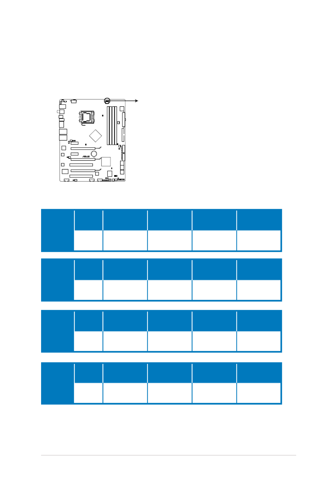
STRIKER II EXTREME
2.2 Motherboard overview
Before you install the motherboard, study the conguration of your chassis to
ensure that the motherboard ts into it.
Make sure to unplug the power cord before installing or removing the
motherboard. Failure to do so can cause you physical injury and damage
motherboard components.
DO NOT overtighten the screws! Doing so can damage the motherboard.
2.2.1 Placement direction
When installing the motherboard, make sure that you place it into the chassis in the
correct orientation. The edge with external ports goes to the rear part of the chassis
as indicated in the image below.
2.2.2 Screw holes
Place nine (9) screws into the holes indicated by circles to secure the motherboard
to the chassis.
Place this side towards
the rear of the chassis

2-6 Chapter 2: Hardware information
2.2.3 Motherboard layout
Refer to 2.8 Connectors for more information about rear panel connectors and
internal connectors.
2.2.4 Audio card layout
S FX IIUPREME
Listen with Absolute HD
24.5cm (9.6in)
30.5cm (12.0in)
STRIKER II EXTREME
DDR3 DIMM_A1 (64bit, 240-pin module)
DDR3 DIMM_A2 (64bit, 240-pin module)
DDR3 DIMM_B1 (64bit, 240-pin module)
DDR3 DIMM_B2 (64bit, 240-pin module)
PCIEX16_1
PCIEX16_3
PCIEX16_2
FLOPPY
VIA
VT6308P
88E1116
88E1116
JMB363
ADH
SPDIF_OUT
NB_CRAZY
NB_HIGH
NB_NORMAL
CPU_CRAZY
CPU_HIGH
CPU_NORMAL
SB_CRAZY
SB_HIGH
SB_NORMAL
DDR_CRAZY
DDR_HIGH
DDR_NORMAL
CHASSIS
CHA_FAN1
EL_CON
LCD_CON
PWR_FAN
OPT_FAN3
OPT_TEMP3
OPT_FAN2
OPT_TEMP2
OPT_TEMP1
OPT_FAN1
CHA_FAN3 HD_LED
PANEL
CHA_FAN2
ROG
IE1394_2 USB78 USB910
CLRTC_SW
PRI_IDE
RESET
SATA1
SATA2
SATA3
SATA4
SATA5
SATA6
PCI1
PCI2
PCIEX1_1
PCIEX1_2
EATX12V
LGA775
EATXPWR
CPU_FAN
FREQUENCY
KB_USB56
SPDIF_O12
E1394
CLR_CMOS
LAN1_USB12
LAN2_USB34
ESATA12
NVIDIA
®
nForce ® 790i(Ultra) SLI™
NVIDIA®
nForce ® 570 SLI™
Super
I/O
Lithium Cell
CMOS Power
BIOS

ROG Striker II Extreme / Striker II NSE 2-7
2.2.5 Layout contents
Slots Page
1. DDR3 DIMM slots 2-18
2. PCI slots 2-24
3. PCI Express x 1 slots 2-24
4. PCI Express x 16 slots 2-24
Slide switch Page
1. Clear RTC RAM (3-pin CLRTC_SW) 2-26
Rear panel connectors Page
1. PS/2 keyboard port (purple) 2-29
2. Coaxial S/PDIF Out port 2-29
3. LAN 2 (RJ-45) port 2-29
4. LAN 1 (RJ-45) port 2-29
5.* Line In port (light blue) 2-30
6.* Line Out port (lime) 2-30
7.* Microphone port (pink) 2-30
8.* Center/Subwoofer port (orange) 2-30
9.* Rear Speaker Out port (black) 2-30
10.* Side Speaker Out port (gray) 2-30
11. USB 2.0 ports 1, 2, 3 and 4 2-30
12. External SATA port 1/2 2-30
13. IEEE 1394a port 2-31
14. Clear CMOS switch 2-31
15. Optical S/PDIF Out port 2-31
16. USB 2.0 ports 5 and 6 2-31
*These audio ports are on the Supreme FX II audio card.

2-8 Chapter 2: Hardware information
Internal connectors Page
1. IDE connector (40-1 pin PRI_IDE) 2-32
2. Serial ATA connectors (7-pin SATA1–6) 2-33
3. Floppy disk drive connector (34-1 pin FLOPPY) 2-34
4. USB connectors (10-1 pin USB78, USB910) 2-34
5. IEEE 1394a port connector (10-1 pin IE1394_2) 2-35
6. Thermal sensor cable connectors (2-pin OPT_TEMP1/2/3) 2-35
7. CPU, chassis, and optional fan connectors
(4-pin CPU_FAN, 3-pin CHA_FAN1–3, 3-pin PWR_FAN,
3-pin OPT_FAN1–3)
2-36
8. Chassis intrusion connector (4-1 pin CHASSIS) 2-37
9. Digital audio connector (4-1 pin SPDIF_OUT, for ASUS HDMI
VGA card) 2-37
10. ATX power connectors (24-pin EATXPWR, 8-pin EATX12V) 2-38
11. ROG connector (2-pin ROG) 2-40
12. System panel connector (20-8 pin PANEL) 2-41
Onboard switches Page
1. Power-on switch 2-43
2. Reset switch 2-43

ROG Striker II Extreme / Striker II NSE 2-9
2.3 Central Processing Unit (CPU)
The motherboard comes with a surface mount LGA775 socket designed for the
Intel® Core™2 Quad / Core™2 Extreme / Core™2 Duo / Pentium
® D / Pentium® 4 /
Pentium® Extreme processors.
•
Upon purchase of the motherboard, make sure that the PnP cap is on
the socket and the socket contacts are not bent. Contact your retailer
immediately if the PnP cap is missing, or if you see any damage to the PnP
cap/socket contacts/motherboard components. ASUS will shoulder the cost
of repair only if the damage is shipment/transit-related.
•
Keep the cap after installing the motherboard. ASUS will process Return
Merchandise Authorization (RMA) requests only if the motherboard comes
with the cap on the LGA775 socket.
• The product warranty does not cover damage to the socket contacts
resulting from incorrect CPU installation/removal, or misplacement/loss/
incorrect removal of the PnP cap.
• Make sure that all power cables are unplugged before installing the CPU.
• If installing a dual-core CPU, connect the chassis fan cable to the
CHA_FAN1 connector to ensure system stability.
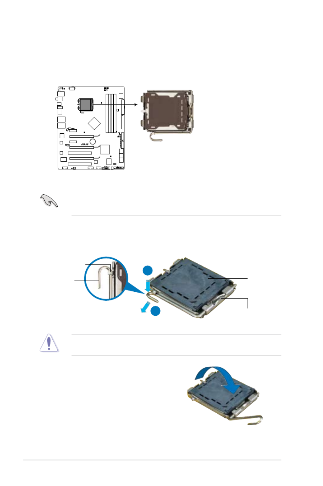
2-10 Chapter 2: Hardware information
3. Lift the load lever in the direction of
the arrow to a 135º angle.
2. Press the load lever with your thumb (A), then move it to the left (B) until it is
released from the retention tab.
Retention tab
Load lever
This side of the socket box
should face you.
PnP cap
A
B
To prevent damage to the socket pins, do not remove the PnP cap unless you
are installing a CPU.
2.3.1 Installing the CPU
To install a CPU:
1. Locate the CPU socket on the motherboard.
Before installing the CPU, make sure that the cam box is facing towards you
and the load lever is on your left.
STRIKER II EXTREME
STRIKER II EXTREME/
STRIKER II NSE CPU socket 775
ROG Striker II Extreme / Striker II NSE 2-11
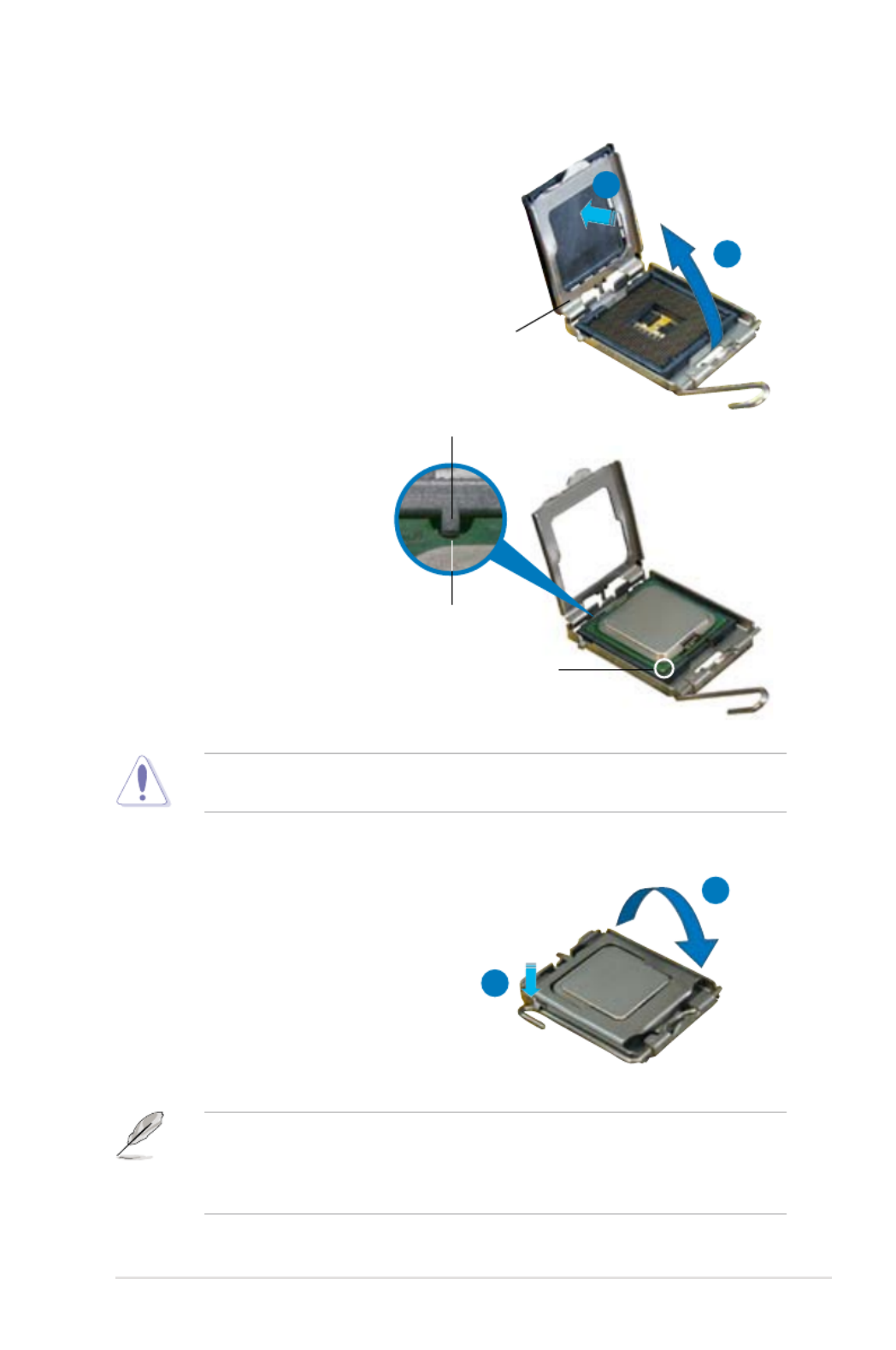
5. Position the CPU over the
socket, making sure that
the gold triangle is on the
bottom-left corner of the
socket then t the socket
alignment key into the
CPU notch.
Alignment key
Gold triangle mark
6. Close the load plate (A), then
push the load lever (B) until it
snaps into the retention tab.
7. If installing a dual-core CPU,
connect the chassis fan cable
to the CHA_FAN1 connector to
ensure system stability.
A
B
The CPU ts in only one correct orientation. DO NOT force the CPU into the
socket to prevent bending the connectors on the socket and damaging the CPU!
The motherboard supports Intel ® LGA775 processors with the Intel ® Enhanced
Memory 64 Technology (EM64T), Enhanced Intel SpeedStep ® Technology
(EIST), and Hyper-Threading Technology. Refer to the Appendix for more
information on these CPU features.
4. Lift the load plate with your thumb
and forenger to a 100º angle (A),
then push the PnP cap from the load
plate window to remove (B).
Load plate
A
B
CPU notch

ROG Striker II Extreme / Striker II NSE 2-13
3. Connect the CPU fan cable to the connector on the motherboard labeled
CPU_FAN.
2. Push down two fasteners at a time
in a diagonal sequence to secure
the heatsink and fan assembly in
place.
B
A
A
A B
B
DO NOT forget to connect the CPU fan connector! Hardware monitoring errors
can occur if you fail to plug this connector.
A
B
STRIKER II EXTREME
CPU_FAN
GND
CPU FAN PWR
CPU FAN IN
CPU FAN PWM
STRIKER II EXTREME/
STRIKER II NSE CPU fan connecto r

2-14 Chapter 2: Hardware information
2.3.3 Uninstalling the CPU heatsink and fan
3. Pull up two fasteners at a time in
a diagonal sequence to disengage
the heatsink and fan assembly from
the motherboard.
B
B
AA
A
A B
B
4. Carefully remove the heatsink
and fan assembly from the
motherboard.
To uninstall the CPU heatsink and fan:
1. Disconnect the CPU fan cable from
the connector on the motherboard.
2. Rotate each fastener
counterclockwise.

ROG Striker II Extreme / Striker II NSE 2-15
5. Rotate each fastener clockwise to
ensure correct orientation when
reinstalling.
Narrow end of the groove
Refer to the documentation in the boxed or stand-alone CPU fan package for
detailed information on CPU fan installation.
The narrow end of the
groove should point outward
after resetting. (The photo
shows the groove shaded for
emphasis.)

2-16 Chapter 2: Hardware information
1. Position the fan above the pipe
and heatsink assembly.
2. Fit the fan to the grooved edge of
the heatsink.
3. Carefully push down the fan until
it snugly ts the heatsink, then
connect the fan cable.
4. The photo shows the fan installed
on the motherboard.
Optional fan on one side ns
• Plug the optional fan cable in the CHA_FAN1/2 connector on the
motherboard.
• Make sure the optional fan is installed correctly to prevent damage to the
fan and motherboard components.
2.3.4 Installing the optional fans
Install TWO optional fans when you are using a water cooler to obtain betterto obtain better
heat dissipation. Installing the optional fans with an active CPU cooler will. Installing the optional fans with an active CPU cooler will
interfere with the airow and destabilize the system.

ROG Striker II Extreme / Striker II NSE 2-17
5. Follow Step 1 to 4 to install the other optional fan.
6. The photo shows that two fans are
installed to the motherboard.
Plug the optional fan cable in the PWR_FAN connector on the motherboard.

2-18 Chapter 2: Hardware information
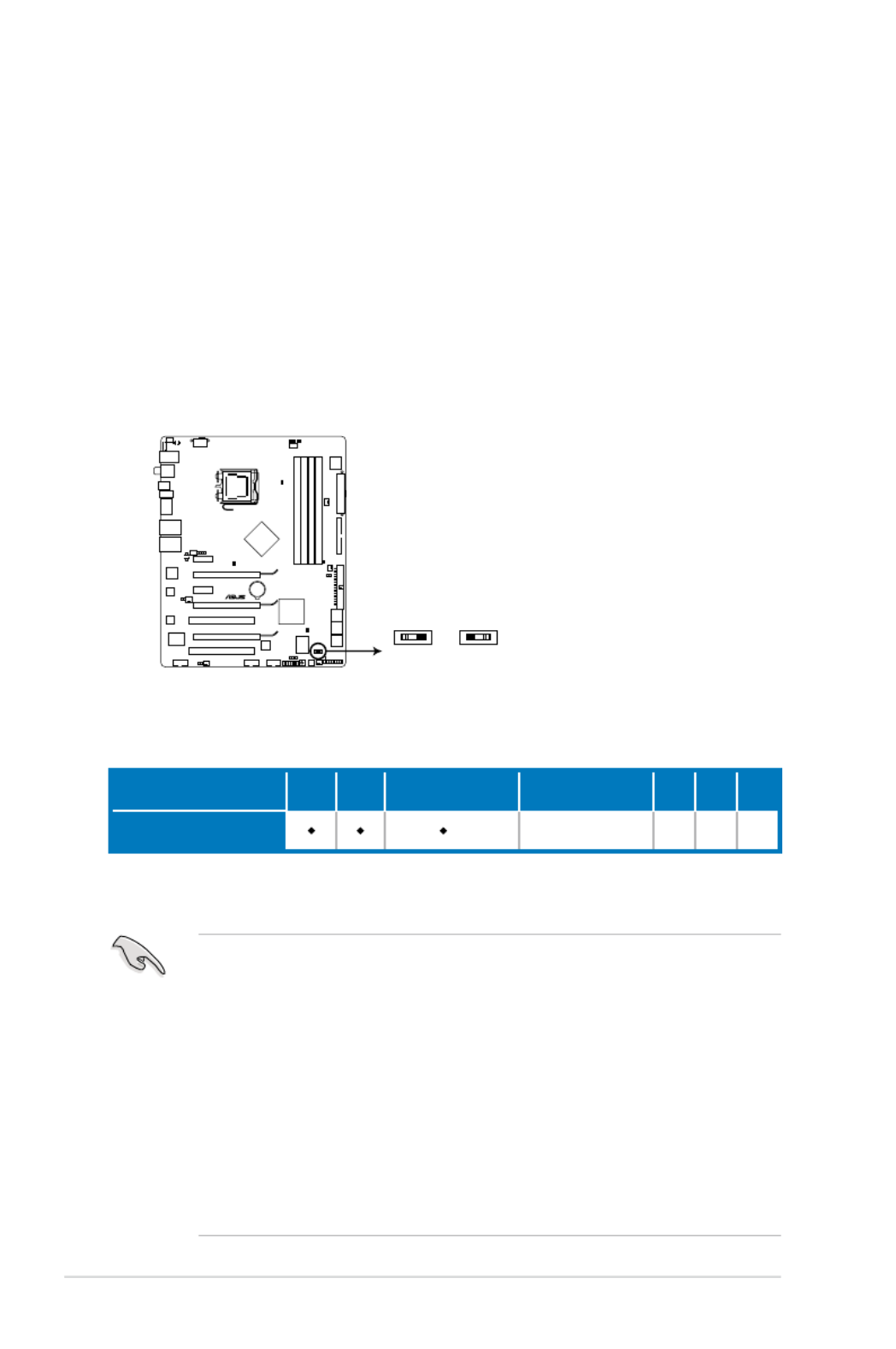
Channel Sockets
Channel A DIMM_A1 and DIMM_A2
Channel B DIMM_B1 and DIMM_B2
2.4 System memory
2.4.1 Overview
The motherboard comes with four Double Data Rate 3 (DDR3) Dual Inline Memory
Modules (DIMM) sockets.
A DDR3 module has the same physical dimensions as a DDR3 DIMM but is
notched differently. DDR3 modules are developed for better performance with less
power consumption.
The gure illustrates the location of the DDR3 DIMM sockets:
The motherboard supports up to 1333MHz and provides more ratio setting
items. Refer to the table below for details.
STRIKER II EXTREME
DIMM_A1
DIMM_A2
DIMM_B1
DIMM_B2
STRIKER II EXTREME/
STRIKER II NSE 240-pin DDR3 DIMM sockets
FSB 1600 1333 1066
DDR3 1600 1333 1066 1333 1066 888 800 1066 852 800 710

ROG Striker II Extreme / Striker II NSE 2-19
2.4.2 Memory congurations
You may install 512 MB, 1 GB, and 2 GB unbuffered non-ECC DDR3 DIMMs into
the DIMM sockets.
Recommended Memory Congurations
• You may install varying memory sizes in Channel A and Channel B. The
system maps the total size of the lower-sized channel for the dual-channel
conguration. Any excess memory from the higher-sized channel is then
mapped for single-channel operation.
• Always install DIMMs with the same CAS latency. For optimum compatibility,
it is recommended that you obtain memory modules from the same vendor.
• If you install four 1 GB memory modules, the system may only recognize less
than 3GB because the address space is reserved for other critical functions.
This limitation appears on Windows ® XP/Vista 32-bit operation system which
does not support Physical Address Extension (PAE).
• If you install Windows ® XP/Vista 32-bit operation system, a total memory of
less than 3GB is recommended.
• Due to chipset resource allocation, the system may detect less than 8 GB
system memory when you installed four 2 GB DDR3 memory modules.
Notes on memory limitations
• Due to chipset limitation, this motherboard can only support up to 8 GB on
the operating systems listed below. You may install a maximum of 2 GB
DIMMs on each slot.
Mode
Sockets
DIMM_A1 DIMM_A2 DIMM_B1 DIMM_B2
Single-Channel
Populated – – –
– – Populated –
Dual-channel (1) Populated – Populated –
Dual-channel (2) Populated Populated Populated Populated
64-bit
Windows ® XP Professional x64 Edition
Windows ® Vista x64 Edition
2-20 Chapter 2: Hardware information
Striker II Extreme / Striker II NSE Motherboard Qualied
Vendors Lists (QVL)
DDR3-1333MHz capability
SS - Single-sided / DS - Double-sided
DIMM support:
• A*: Supports one module inserted in any slot as Single-channel memory
conguration.
• B*: Supports one pair of modules inserted into either the blue slots or the
white slots as one pair of Dual-channel memory conguration.
• C*: Supports four modules inserted into both the blue and white slots as
two pairs of Dual-channel memory conguration.
�isit the ASUS website for the latest DDR3-2000/1800/1600/1333/1066/800MHz
QVL.
Size Vendor Chip No.
SS/
DS Part No.
DIMM support
A* B* C*
512MB ELPIDA J5308BASE-DG-E SS EBJ51UD8BAFA-DG-E •
1024MB ELPIDA J5308BASE-DG-E DS EBJ11UD8BAFA-DG-E
1024MB ELPIDA J5308BASE-DJ-E DS EBJ11UD8BAFA-DJ-E
1024MB SAMSUNG K4B1G0846C-ZCF8 SS M378B2873CZ0-CG9 • •
1024MB SAMSUNG K4B1G0846C-ZCH9 SS M378B2873CZ0-CH9 • •
512MB Kingston IDSH51-03A1F1C-13G SS KVR1333D3N8/512 •
1024MB Kingston Heat-Sink Package DS KHX11000D3LL/1G
1024MB Kingston IDSH51-03A1F1C-13G DS KVR1333D3N8/1G • • •
1024MB CORSAIR Heat-Sink Package DS CM3X1024-1333C9DHX • • •
2048MB MICRON Z9HWR DS MT16JTF25664AY-1G4BYES • •
512MB OCZ Heat-Sink Package SS OCZ3P13331GK
1024MB OCZ Heat-Sink Package DS OCZ3P13332GK
1024MB OCZ Heat-Sink Package SS OCZ3RPX1333EB2GK
1024MB PNY IDSH51-03A1F1C-10F DS 89000632-H-PH0
ROG Striker II Extreme / Striker II NSE 2-21
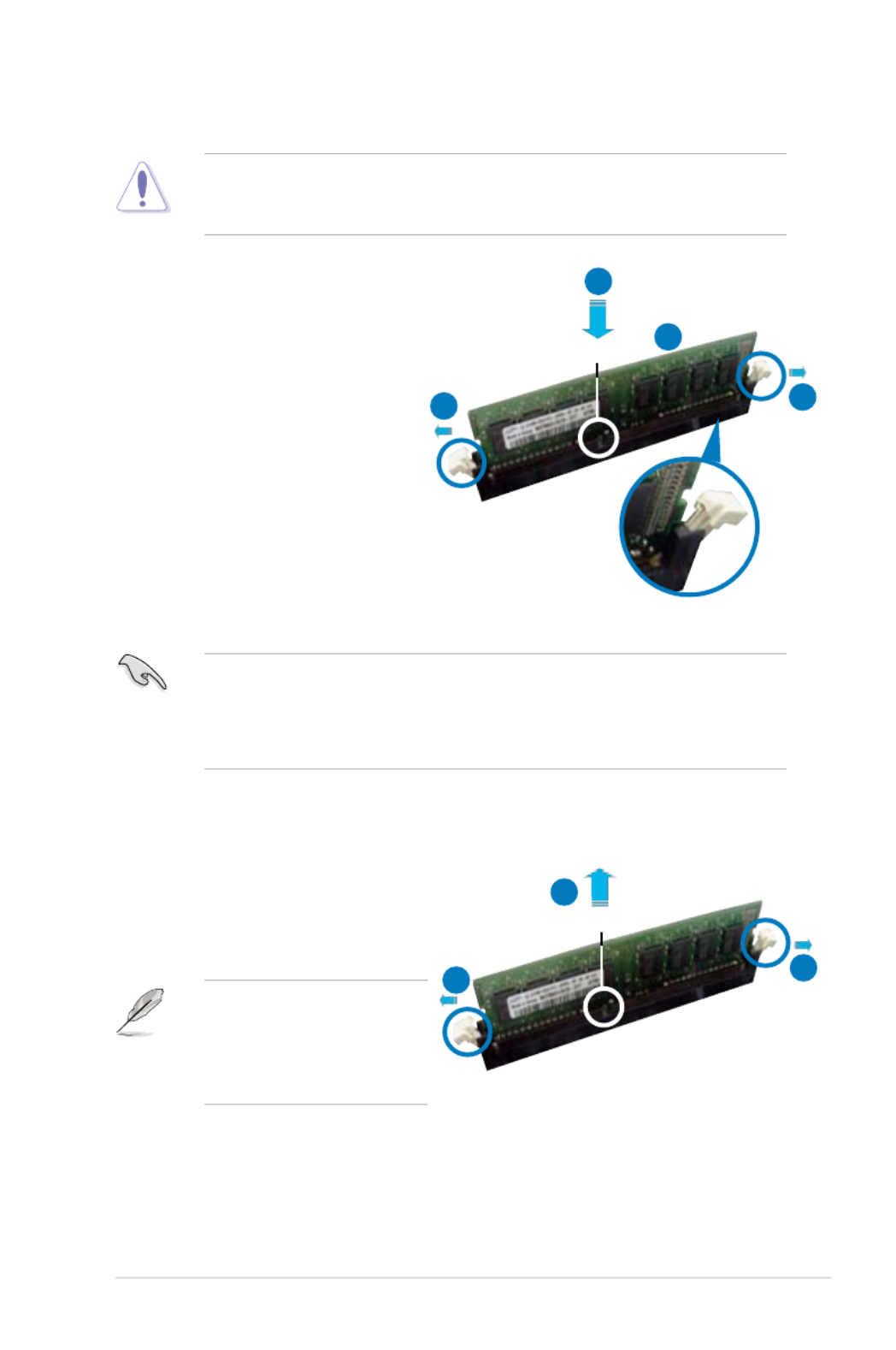
2.4.3 Installing a DIMM
Unplug the power supply before adding or removing DIMMs or other
system components. Failure to do so can cause severe damage to both the
motherboard and the components.
To install a DIMM:
1. Unlock a DIMM socket by
pressing the retaining clips
outward.
2. Align a DIMM on the socket
such that the notch on the
DIMM matches the break on the
socket.
3. Firmly insert the DIMM into the
socket until the retaining clips
snap back in place and the
DIMM is properly seated.
2.4.4 Removing a DIMM
To remove a DIMM:
1. Simultaneously press the retaining
clips outward to unlock the DIMM.
2. Remove the DIMM from the socket.
Support the DIMM lightly with
your ngers when pressing
the retaining clips. The DIMM
might get damaged when it
ips out with extra force.
• A DDR3 DIMM is keyed with a notch so that it ts in only one direction. Do
not force a DIMM into a socket to avoid damaging the DIMM.
• The DDR3 DIMM sockets do not support DDR or DDR2 DIMMs. Do not
install DDR or DDR2 DIMMs to the DDR3 DIMM sockets.
Unlocked retaining clip
DDR3 DIMM notch
1
2
3
1
2
DDR3 DIMM notch
11

2-22 Chapter 2: Hardware information
2.5 Expansion slots
In the future, you may need to install expansion cards. The following sub-sections
describe the slots and the expansion cards that they support.
2.5.1 Installing an expansion card
To install an expansion card:
1. Before installing the expansion card, read the documentation that came with
it and make the necessary hardware settings for the card.
2. Remove the system unit cover (if your motherboard is already installed in a
chassis).
3. Remove the bracket opposite the slot that you intend to use. Keep the screw
for later use.
4. Align the card connector with the slot and press rmly until the card is
completely seated on the slot.
5. Secure the card to the chassis with the screw you removed earlier.
6. Replace the system cover.
2.5.2 Conguring an expansion card
After installing the expansion card, congure it by adjusting the software settings.
1. Turn on the system and change the necessary BIOS settings, if any. See
Chapter 4 for information on BIOS setup.
2. Assign an IRQ to the card. Refer to the tables on the next page.
3. Install the software drivers for the expansion card.
Make sure to unplug the power cord before adding or removing expansion
cards. Failure to do so may cause you physical injury and damage motherboard
components.
When using PCI cards on shared slots, ensure that the drivers support “Share
IR�” or that the cards do not need IR� assignments. Otherwise, conicts will
arise between the two PCI groups, making the system unstable and the card
inoperable. Refer to the table on the next page for details.

ROG Striker II Extreme / Striker II NSE 2-23
2.5.3 Interrupt assignments
IRQ assignments for this motherboard
A B C D E F G H
PCI slot 1 shared – – – – – – –
LAN (1116) shared – – – – – – –
SATA (363) shared – – – – – – –
LAN (1116) – shared – – – – – –
PCIe x16_1 shared – – – – – – –
PCIe x16_2 shared – – – – – – –
PCIe x16_3 shared – – – – – – –
PCIe x1_1 – shared – – – – – –
PCIe x1_2 shared – – – – – – –
USB controller 1 – – – – – – shared
USB controller 2 – – – shared – – – –
USB controller 3 – – shared – – – – –
USB controller 4 shared – – – – – – –
USB controller 5 – – – – – shared – –
USB controller 6 – – shared – – – – –
USB 2.0 controller 1 – – – – – – – shared
USB 2.0 controller 2 – – shared – – – – –
SATA controller 1 – – – – – – shared –
SATA controller 2 – – – – – – shared –
IRQ Standard function
0 System timer
1 Keyboard controller
6 Floppy disk controller
8 System CMOS/Real Time Clock
9 IRQ holder for PCI steering
10 NVIDIA nForce PCI system management
11 IRQ holder for PCI steering
12 PS/2 compatible mouse port
13 Numeric data processor
14 Primary IDE channel
19 VIA OHCI compliant IEEE 1394 host controller
20 NVIDIA network bus enumerator
20 NVIDIA nForce Serial ATA controller
21 NVIDIA network bus enumerator
21 Standard Enhanced PCI to USB host controller
22 Microsoft UAA bus driver for High Denition audio
22 nForce Serial ATA controller
23 nForce Serial ATA controller
23 Standard OpenHCD USB host controller

2-24 Chapter 2: Hardware information
2.5.4 PCI slots
The PCI slots support cards such as a LAN card, SCSI card, USB card, and other
cards that comply with PCI specications. Refer to the gure below for the location
of the slots.
2.5.5 PCI Express p50-x1 slots
This motherboard supports PCI Express p50-x1 network cards, SCSI cards and other
cards that comply with the PCI Express specications. Refer to the gure below for
the location of the slots.
• Install the audio card prior to other compatible cards to the black PCIe p50-x1
slot.
• Install a PCIe p50-x1 device to a PCIe p50-x1 slot prior to a PCIe x16 slot.
2.5.6 PCI Express x16 slots
This motherboard supports three SLI™-ready Express x16 graphics cards that
comply with the PCI Express specications. With three graphics cards installed,
the motherboard enables tri-display. Two (blue slots) of the three PCI Express x16
slots support PCIe 2.0 devices.
PCI Express x 1 slot PCI slot
PCI Express x 16 slot
PCI slot
PCI Express x16 slot
Audio/PCI Express p50-x1 slot
PCI Express x 16 slot

ROG Striker II Extreme / Striker II NSE 2-25
• We recommend that you install a VGA card to the primary (blue) PCI
Express x16 slots, and install any other PCI Express device to the universal
(white) PCI Express x16 slot.
• Currently, only NVIDIA ® SLI™-Ready GeForce ® 8800 Ultra and GeForce ®
8800 GTX graphics cards support 3-Way SLI™ mode.
• Connect a rear chassis fan to the motherboard connector labeled
CHA_FAN2 or OPT_FAN1/2/3 when using multiple graphics cards for better
thermal environment. See page 2-35 for details.
• In single VGA card mode, use any of the PCIe 2.0 slots (blue) for a PCI
Express x16 graphics card to get better performance.
• In SLI™ mode, use the PCIe 2.0 slots (blue slots) for PCI Express x16
graphics cards to get better performance.
• We recommend that you provide sufcient power when running N�IDIA ®
SLI™ mode. See page 2-37 for details.
2-26 Chapter 2: Hardware information
2.6 Slide switch
1. Clear RTC RAM (3-pin CLRTC_SW)
This onboard slide switch allows you to enable the clr CMOS switch on the
back I/O. You can clear the CMOS memory and system setup parameters
by erasing the CMOS RTC RAM data. The clr CMOS switch on the back
I/O helps you easily to clear the system setup information such as system
passwords.
To erase the RTC RAM:
1. Press down the clr CMOS switch on the back I/O.
2. Hold down the <Del> key during the boot process and enter BIOS setup
to re-enter data.
clr CMOS switch behavior
System power state G3* S5* S0 (DOS mode) S0 (OS mode) S1 S3 S4
Clearing CMOS **
*G3: Power off without +5VSB power (AC power loss); S5: Power off with +5VSB power
**The system shuts down immediately.
• The clr CMOS switch will not function if the CLRTC_SW switch is moved
to the Disable position, but the shutdwon function in S0 mode (DOS mode)
still works.
• Make sure to re-enter your previous BIOS settings after you clear the
CMOS.
• You do not need to clear the RTC when the system hangs due to CPU
overclocking. With the C.P.R. (CPU Parameter Recall) feature, shut down
and reboot the system so the BIOS can automatically reset CPU parameter
settings to default values. If the system hangs due to overclocking of
memory timing or chipset voltage and the power button fails to function,
pressing down the clr CMOS switch will shut down the system and clear
CMOS simultaneously.
STRIKER II EXTREME
Enable
(Default)
Disable
CLRTC_SW
STRIKER II EXTREME/
STRIKER II NSE Clear RTC RAM slide switch
ROG Striker II Extreme / Striker II NSE 2-33
2. Serial ATA connectors (7-pin SATA1–6)
These connectors are for the Serial ATA signal cables for Serial ATA hard disk
drives.
If you installed Serial ATA hard disk drives, you can create a RAID 0, RAID 1,
® MediaShield™
RAID controller.
• In Standard IDE mode, you can connect Serial ATA boot/data hard disk
drives to these connectors. If you intend to create a Serial ATA RAID set
using these connectors, enable the [RAID Enabled] item in the BIOS. See
section 4.5.6 Serial-ATA Conguration for details.
• For RAID 5, use at least three hard disk drives. For RAID 0+1, use at least
four hard disk drives. Use two to four Serial ATA hard disk drives for each
RAID 0 or RAID 1 set.
• Before creating a RAID set, refer to 5.4.2 NVIDIA ® RAID congurations or
the manual bundled in the motherboard support DVD.
Connect the right-angle side
of SATA signal cable to SATA
device. Or you may connect the
right-angle side of SATA cable to
the onboard SATA port to avoid
graphics cards.
right angle side
You must install the Windows ® XP Service Pack 1 before using Serial ATA hard
disk drives. The Serial ATA RAID feature (RAID 0/RAID 1/RAID 5/RAID 10) is
available only if you are using Windows ® XP or later version.
STRIKER II EXTREME
GND
RSATA_TXP1
RSATA_TXN1
GND
RSATA_RXP1
RSATA_RXN1
GND
SATA1
GND
RSATA_TXP2
RSATA_TXN2
GND
RSATA_RXP2
RSATA_RXN2
GND
SATA2
GND
RSATA_TXP3
RSATA_TXN3
GND
RSATA_RXP3
RSATA_RXN3
GND
SATA3
GND
RSATA_TXP4
RSATA_TXN4
GND
RSATA_RXP4
RSATA_RXN4
GND
SATA4
GND
RSATA_TXP5
RSATA_TXN5
GND
RSATA_RXP5
RSATA_RXN5
GND
SATA5
GND
RSATA_TXP6
RSATA_TXN6
GND
RSATA_RXP6
RSATA_RXN6
GND
SATA6
STRIKER II EXTREME/
STRIKER II NSE SATA connector

2-34 Chapter 2: Hardware information
4. USB connectors (10-1 pin USB 78; USB 910)
These connectors are for USB 2.0 ports. Connect the USB module cable
to any of these connectors, then install the module to a slot opening at the
back of the system chassis. These USB connectors comply with USB 2.0
specication that supports up to 480 Mbps connection speed.
Never connect a 1394 cable to the USB connectors. Doing so will damage the
motherboard!
You can connect the USB cable to ASUS �-Connector (USB, blue) rst, and
then install the Q-Connector (USB) to the USB connector onboard.
3. Floppy disk drive connector (34-1 pin FLOPPY)
This connector is for the provided oppy disk drive (FDD) signal cable. Insert
one end of the cable to this connector, then connect the other end to the
signal connector at the back of the oppy disk drive.
Pin 5 on the connector is removed to prevent incorrect cable connection when
using a FDD cable with a covered Pin 5.
STRIKER II EXTREME
FLOPPY
NOTE:Orient the red markings
on the floppy ribbon cable to PIN 1.
PIN1
STRIKER II EXTREME/
STRIKER II NSE Floppy disk drive connector
STRIKER II EXTREME
PIN 1
USB+5V
USB_P8-
USB_P8+
GND
NC
USB+5V
USB_P7-
USB_P7+
GND
USB78
PIN 1
USB+5V
USB_P10-
USB_P10+
GND
NC
USB+5V
USB_P9-
USB_P9+
GND
USB910
STRIKER II EXTREME/
STRIKER II NSE USB2.0 connectors
ROG Striker II Extreme / Striker II NSE 2-35
5. IEEE 1394a port connector (10-1 pin IE1394_2)
This connector is for a IEEE 1394a port. Connect the IEEE 1394a module
cable to this connector, then install the module to a slot opening at the back
of the system chassis.
Never connect a USB cable to the IEEE 1394a connector. Doing so will damage
the motherboard!
You can connect the 1394 cable to ASUS �-Connector (1394, red) rst, and
then install the Q-Connector (1394) to the 1394 connector onboard.
6. Thermal sensor cable connectors (2-pin OPT_TEMP1/2/3)
These connectors are for temperature monitoring. Connect the thermal
sensor cables to these connectors and place the other ends to the devices
which you want to monitor temperature. The optional fan1/2/3 can work with
the temperature sensors for a better cooling effect.
Enable in BIOS if you connect thermal OPT1/2/3 Cable Overheat Protection
sensor cables to these connectors. Refer to page 4-35 for details.
STRIKER II EXTREME
PIN 1
TPA2-
GND
TPB2-
+12V
GND
TPA2+
GND
TPB2+
+12V
IE1394_2
STRIKER II EXTREME/
STRIKER II NSE IEEE 1394 connector
STRIKER II EXTREME
Temperature
Ground
OPT_TEMP3
Temperature
Ground
OPT_TEMP2
Temperature
Ground
OPT_TEMP1
STRIKER II EXTREME/
STRIKER II NSE Thermal sensor cable connectors

2-38 Chapter 2: Hardware information
•
For a fully congured system, we recommend that you use a power supply
unit (PSU) that complies with ATX 12 � Specication 2.0 (or later version)
and provides a minimum power of 400 W.
• Do not forget to connect the 4-pin/8pin EATX12� power plug; otherwise,
the system will not boot.
• Use of a PSU with a higher power output is recommended when
conguring a system with more power-consuming devices. The system
may become unstable or may not boot up if the power is inadequate.
• If you are uncertain about the minimum power supply requirement for your
system, refer to the Recommended Power Supply Wattage Calculator
at http://support.asus.com/PowerSupplyCalculator/PSCalculator.
aspx?SLanguage=en-us for details.
• If you want to use two high-end PCI Express p64-x16 cards, use a PSU with
500W to 600W power or above to ensure the system stability.
• If you want to use 3-Way SI™ conguration, visit the N�IDIA website
(www.nvidia.com) for the qualied PSU vendor list.
10. ATX power connectors (24-pin EATXPWR, 8-pin EATX12V)
These connectors are for ATX power supply plugs. The power supply plugs
are designed to t these connectors in only one orientation. Find the proper
orientation and push down rmly until the connectors completely t.
• Make sure to remove the cap on the EATX12V connector before connecting
an 8-pin EPS +12V power plug.
• Use only an 8-pin EPS +12V power plug for the EATX12V connector.
STRIKER II EXTREME
EATXPWR
PIN 1
GND
+5 Volts
+5 Volts
+5 Volts
-5 Volts
GND
GND
GND
PSON#
GND
-12 Volts
+3 Volts
+3 Volts
+12 Volts
+12 Volts
+5V Standby
Power OK
GND
+5 Volts
GND
+5 Volts
GND
+3 Volts
+3 Volts
EATX12V
PIN 1
+12V DC
+12V DC
+12V DC
+12V DC
GND
GND
GND
GND
STRIKER II EXTREME/
STRIKER II NSE ATX power connectors

2-42 Chapter 2: Hardware information
ASUS Q-Connector (system panel)
You can use the ASUS Q-Connector to connect/disconnect chassis front panel
cables in a few steps. Refer to the instructions below to install the ASUS Q-
Connector.
1. Connect the front panel cables to the
ASUS Q-Connector.
Refer to the labels on the Q-Connector
to know the detailed pin denitions, then
match them to the respective front panel
cable labels.
2. Install the ASUS Q-Connector to the
system panel connector, making sure
the orientation matches the labels on the
motherboard.
3. The front panel functions are now enabled.
The gure shows the �-Connector properly
installed on the motherboard.

2-46 Chapter 2: Hardware information
2.8.5 Installing the DIY Pedestal
1. Take out the DIY Pedestal from
the motherboard package.
2. Arrange and stick the DIY Pedestal to the back of your motherboard.
3. Place the motherboard with the
DIY Pedestal as desired to get
more efcient heat dissipation.
• The tape on the rubber studs is for one-time use. Replace the tape if the
adhesive surface does not work.
• You can use the DIY Pedestal in ways that suit your needs.

3
Chapter 3: Powering up
This chapter describes the power up
sequence, the vocal POST messages,
and ways of shutting down the system.
Produktspecifikationer
| Varumärke: | Asus |
| Kategori: | moderkort |
| Modell: | Striker II Extreme |
| Färg på produkten: | Grijs |
| Inbyggd display: | Ja |
| Vikt: | 600 g |
| Bredd: | 145 mm |
| Djup: | 120 mm |
| Höjd: | 35 mm |
| Användarmanual: | Ja |
| Blåtand: | Ja |
| Processorfrekvens: | 742 MHz |
| Processormodel: | BCM73625 |
| Bluetooth-version: | 4.0 |
| Inkluderar operativsystem: | Linux |
| Ethernet LAN: | Ja |
| Videolägen som stöds: | 480i, 480p, 576i, 576p, 720p, 1080i, 1080p |
| Videokomprimeringsformat: | H.265, HEVC |
| Medföljande kablar: | IR |
| Integrerad minneskortläsare: | Nee |
| Inbyggd hårddisk: | Nee |
| Inkluderar AC-adapter: | Ja |
| Antal USB 2.0-portar: | 2 |
| Antal HDMI-portar: | 2 |
| Antal Ethernet LAN (RJ-45)-portar: | 1 |
| Strömförbrukning (i standby): | 0.5 W |
| Anslutning för nätadapter: | Ja |
| HD typ: | Full HD |
| Internminne: | 512 MB |
| Internminnestyp: | DDR3 |
| Plug and play: | Ja |
| Typ av tuner: | Digitaal |
| Digitalt signalformat: | DVB-C, DVB-S2, DVB-T2 |
| Tidsförskjutning: | Ja |
| Typ processor: | Ja |
| Text-TV: | Ja |
| Elektronisk TV-guide: | Ja |
| On Screen Display (OSD): | Ja |
| Antal RF-portar: | 1 |
| Ethernet LAN, dataöverföringshastigheter: | 10, 100 Mbit/s |
| RS-232: | Ja |
| Att dra tillbaka: | Ja |
| Antal tuners: | 2 tuner(s) |
| Processorfabrikant: | Broadcom |
| SmartCard-kortplats: | Ja |
| Ljudutgångskanaler: | - kanalen |
| Flashminne: | 512 MB |
| Interaktiv TV: | Nee |
| S/PDIF-utgång: | Ja |
| Programmerbara timers: | Ja |
| Fjärrkontroll ingår: | Ja |
| Signalkälla: | Ethernet (RJ-45), Satellite, Terrestrial, WLAN |
| Personal Video Recorder (PVR) ingår: | Nee |
| Webbsurfning online: | Ja |
| Wifi: | Ja |
| Batterier-ingår: | Ja |
| Type beeldscherm: | LED |
| Digital Satellite Equipment Control (DiSEqC): | 1.0, 1.1, 1.2, 1.3 |
| Antal fack för smartkort: | 1 |
| Förmåga att titta och spela in: | Ja |
Behöver du hjälp?
Om du behöver hjälp med Asus Striker II Extreme ställ en fråga nedan och andra användare kommer att svara dig
moderkort Asus Manualer

3 April 2025
3 April 2025
3 April 2025
3 April 2025
2 April 2025
2 April 2025
1 April 2025
27 Mars 2025
27 Mars 2025
12 Februari 2025
moderkort Manualer
- moderkort Sharkoon
- moderkort Gigabyte
- moderkort Asrock
- moderkort Supermicro
- moderkort Evga
- moderkort Intel
- moderkort MSI
- moderkort ECS
- moderkort NZXT
- moderkort Foxconn
- moderkort Advantech
- moderkort Elitegroup
- moderkort EPoX
- moderkort Biostar
Nyaste moderkort Manualer
30 Mars 2025
25 Mars 2025
10 Mars 2025
3 Mars 2025
3 Mars 2025
3 Mars 2025
3 Mars 2025
3 Mars 2025
3 Mars 2025