Asus Z97-PRO Bruksanvisning
Läs nedan 📖 manual på svenska för Asus Z97-PRO (180 sidor) i kategorin moderkort. Denna guide var användbar för 26 personer och betygsatt med 4.5 stjärnor i genomsnitt av 2 användare
Sida 1/180

Motherboard
Z97-PRO
Series
Copyright© 2014 ASUSTeK COMPUTER INC. All Rights Reserved.
Offer to Provide Source Code of Certain Software
gpl@asus.com

Contents
Safety information vi ......................................................................................................
About this guide vii ........................................................................................................
Z97-PRO specifications summary ix ............................................................................
Package contents xv ......................................................................................................
Installation tools and components xvi .........................................................................
Chapter 1: Product Introduction
1.1 Special features.......................................................................................... 1-1
1.2 Motherboard overview 1-3 ...............................................................................
Chapter 2: Basic installation
2.1 Building your PC system 2-1 ...........................................................................
2.2 BIOS update utility 2-12 ...................................................................................
2.3 Motherboard rear and audio connections 2-14 .............................................
2.4 Starting up for the first time 2-18 ....................................................................
2.5 Turning off the computer 2-19 ........................................................................

Safety information
Electrical safety
Operation safety

xiv
Internal
2 x 19-pi
2 x USB 2.1 x M.2 So1 x SATA E6 x SATA 61 x 4-pin C(PWM mod1 x 4-pin C4 x 4-pin C(PWM mod1 x Front p1 x S/PDIF1 x 5-pin T1 x TPM co1 x 24-pin E1 x 8-pin E1 x MemOK1 x Clear C1 x USB BI1 x DRCT 1 x TPU sw1 x EPU sw1 x EZ XM1 x Power-o1 x System
* The CPU Q-
g
BIO
64 Mb FlasBIOS 2.7, A
CrashFree BFavorites, Q
F3 ShortcutDetect) me
ManSupp
DriversASUS UtiliEZ UpdateAnti-virus s
Opesupp
Windows
8.1
Windows
8
Windows
7
Form
Specicatio

Package contents
ASUS Z97-PRO motherboard
User manual
Support DVD
4 x Serial ATA 6 Gb/s cables
1 x ASUS SLI™ bridge connector
1 x ASUS Q-Shield
User Manual
1 x 2-in-1 ASUS Q-Connector kit
1 x 2T2R dual-band Wi-Fi moving antennas
(Wi-Fi 802.11a/b/g/n/ac compliant) (Optional)
Chapter 1
3.5 Ai Tweaker menu
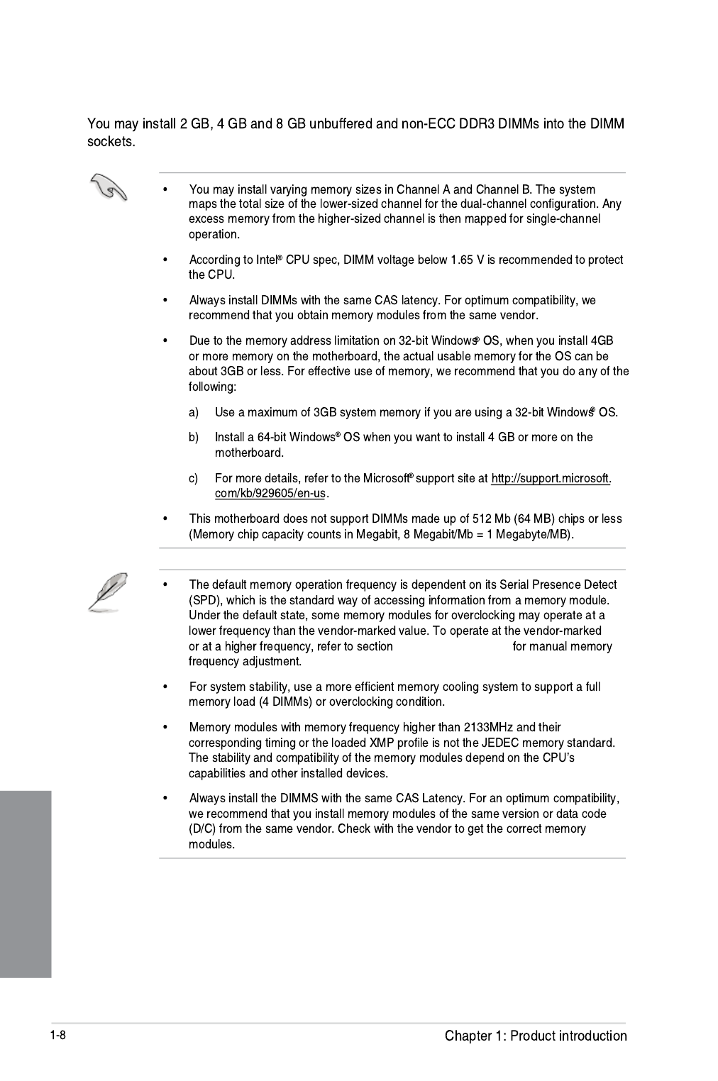
Memory configurations

Chapter 1
Z97-PRO Motherboard Qualified Vendors Lists (QVL)
DDR3 3200 (O.C.) MHz capability
DDR3 3100 (O.C.) MHz capability
DDR3 3000 (O.C.) MHz capability
DDR3 2933 (O.C.) MHz capability
Vendors Part No. Size SS/DS Chip Brand Chip
NO.
Timing Voltage DIMM socket
support (Optional)
1 2 4
Vendors Part No. Size SS/DS Chip Brand Chip
NO.
Timing Voltage DIMM socket
support (Optional)
1 2 4
Vendors Part No. Size SS/
DS
Chip Brand Chip
NO.
Timing Voltage DIMM socket
support (Optional)
1 2 4
Vendors Part No. Size SS/
DS
Chip
Brand
Chip NO. Timing Voltage DIMM socket
support (Optional)
1 2 4

Chapter 1
DDR3 1600 MHz capability
Vendors Part No. Size SS/
DS
Chip
Brand
Chip NO. Timing DIMM socket Voltage
support (Optional)
124

Chapter 1
Vendors Part No. Size SS/
DS
Chip
Brand
Chip NO. Timing Voltage DIMM socket
support
(Optional)
1 2 4
DDR3 1333 MHz capability
Chapter 1
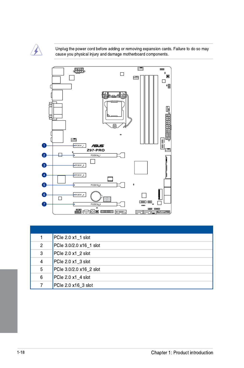
1.2.5 Expansion slots
Slot No. Slot Description

1-19
Chapter 1
mode.
using multiple graphics cards for better thermal environment.
IRQ assignments for this motherboard
A B C D E F G H
PCIe x16_1 shared – – – – – – –
PCIe x16_2 – shared – – – – – –
PCIe x16_3 shared – – – – – – –
PCIe x1_1 shared – – – – – – –
PCIe x1_2 –– – shared – – – –
PCIe x1_3 shared – – – – – – –
PCIe x1_4 – – shared – – – – –
SMBUS Controller – – shared – – – – –
Wi-Fi/Bluetooth 4.0
(Optional) – shared – – – – –
Intel® SATA Controller – – – shared – – – –
Intel®– – ––shared – – –
ASMedia SATA
Controller (1061) – – – shared – – – –
Intel® xHCI – – – – – shared – –
Intel® EHCI 1 – – – – – – – shared
Intel® EHCI 2 shared – – – – – – –
HD Audio – – – – – – shared –
ASMedia Controller
(1142) – shared – – – – –
VGA configuration
PCI Express 3.0 operating mode
PCIe 3.0/2.0 x16_1 PCIe 3.0/2.0 x16_2
Single VGA/PCIe card p35-x16 (single VGA
recommended) N/A
Dual VGA/PCIe card
Chapter 1
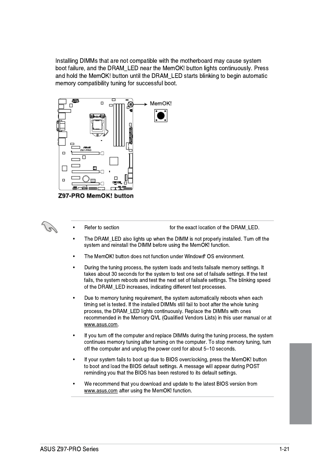
3. MemOK! button
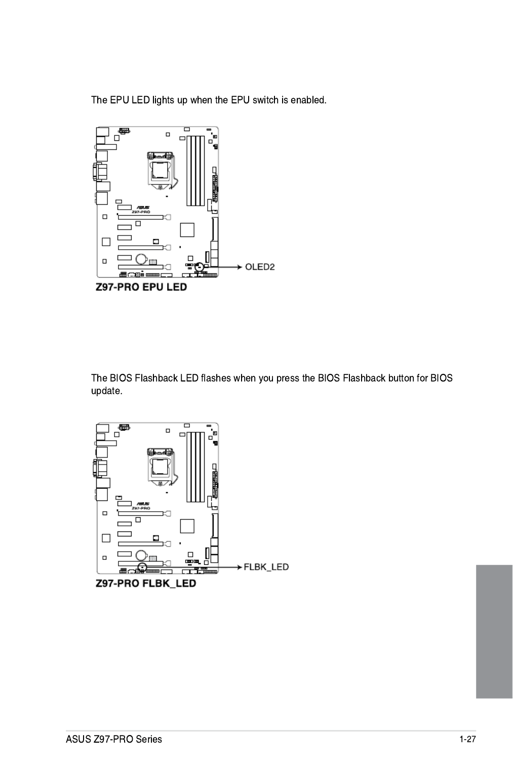
1.2.8 Onboard LEDs
Chapter 1
3. EPU LED (OLED2)
4. USB BIOS Flashback LED (FLBK_LED)

Chapter 1
Q-Code table
Code Description
00
01
02
03
04
06
07
08
09
0B
0C – 0D
0E
0F
10
11 – 14
15 – 18
19 – 1C
2B – 2F
30
31
32 – 36
37 – 3A
3B – 3E
4F
50 – 53
54
55
56
57
58
59
5A
5B
5C – 5F
E0
E1
E2
E3
E4 – E7
E8
2-6 Chapter 2: Basic installation
Chapter 2
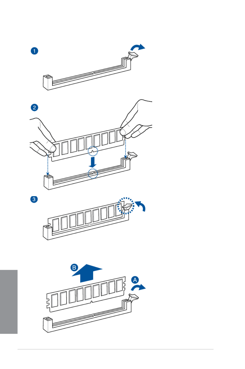
To remove a DIMM
2.1.4 DIMM installation

2-8 Chapter 2: Basic installation
Chapter 2
2.1.6 SATA device connection
OR
OR

ASUS Z97-PRO Series 2-9
Chapter 2
2.1.7 Front I/O Connector
To install ASUS Q-Connector
USB 2.0
AAFP
To install USB 2.0 connector To install front panel audio connector
USB 3.0
To install USB 3.0 connector
HDD LED
POWER SW
RESET SW
HDD LED-
HDD LED+
PWR
Reset
Ground
Ground
HDD LED
ASUS Z97-PRO Series 2-11
Chapter 2
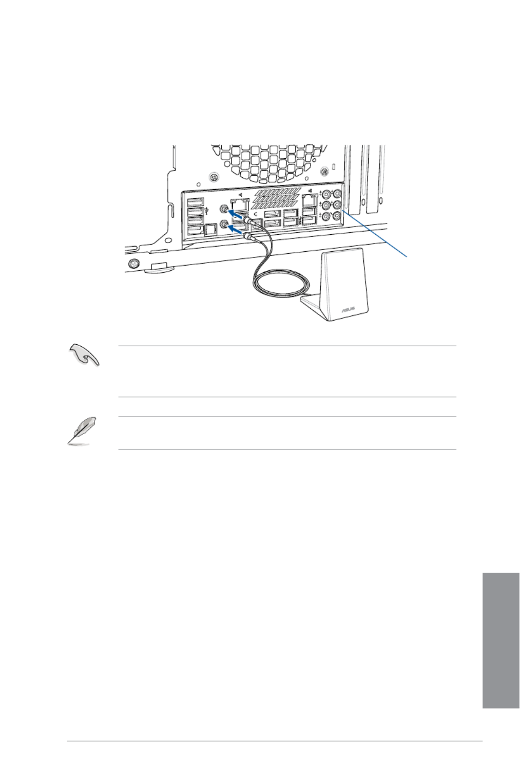
2.1.9 Wi-Fi antenna installation (Optional)
Installing the ASUS 2T2R dual band W-Fi antenna
Connect the bundled ASUS 2T2R dual band Wi-Fi antenna connector to the Wi-Fi ports at
the back of the chassis.
POWER eSATA 6G
S/PDIF
USB3.0
USB BIOS Flashback
USB3.0
REAR
SPK CTR
BASS
LINE
IN
KY
FRONTMIC IN
IO Shield
• EnsurethattheASUS2T2RdualbandWi-FiantennaissecurelyinstalledtotheWi-Fi
ports.
• EnsuretoinstalltheBluetoothdriverbeforeinstallingtheWi-FiGO!software.
The illustration above is for reference only. The I/O port layout may vary with models, but
the Wi-Fi antenna installation procedure is the same for all models.

2-12 Chapter 2: Basic installation
Chapter 2
2.2 BIOS update utility
USB BIOS Flashback
USBBIOSFlashbackallowsyoutoeasilyupdatetheBIOSwithoutenteringtheexisting
BIOSoroperatingsystem.SimplyinsertaUSBstoragedevicetotheUSBportthenpress
theUSBBIOSFlashbackbuttonforthreesecondstoautomaticallyupdatetheBIOS.
To use USB BIOS Flashback:
1. PlacethebundledsupportDVDtotheopticaldriveandinstalltheUSBBIOS
Flashback Wizard. Follow the onscreen instructions to complete the installation.
2. InserttheUSBstoragedevicetotheUSBFlashbackport.
• WerecommendyoutouseaUSB2.0storagedevicetosavethelatestBIOSversion
for better compatibility and stability.
• Refertosection2.3.1RearI/OconnectionforthelocationoftheUSBportthat
supportsUSBBIOSFlashback.
3. LaunchtheUSBBIOSFlashbackWizardtoautomaticallydownloadthelatestBIOS
version.
4. Shut down your computer.
5. Onyourmotherboard,presstheBIOSFlashbackbuttonforthreesecondsuntilthe
FlashbackLEDblinksthreetimes,indicatingthattheBIOSFlashbackfunctionis
enabled.
Refer to section 1.2.8 Onboard LEDs for more information of the Flashback LED.

ASUS Z97-PRO Series 2-13
Chapter 2
• Donotunplugportabledisk,powersystem,orpresstheCLR_CMOSbuttonwhile
BIOSupdateisongoing,otherwiseupdatewillbeinterrupted.Incaseofinterruption,
please follow the steps again.
• Ifthelightashesforvesecondsandturnsintoasolidlight,thismeansthatthe
BIOSFlashbackisnotoperatingproperly.Thismaybecausedbyimproperinstallation
oftheUSBstoragedeviceandlename/leformaterror.Ifthisscenariohappens,
please restart the system to turn off the light.
• UpdatingBIOSmayhaverisks.IftheBIOSprogramisdamagedduringtheprocess
and results to the system’s failure to boot up, please contact your local ASUS Service
Center.
FormoreBIOSupdateutilitiesinBIOSsetup,refertothesection3.11 Updating BIOS in
Chapter 3.
6. Waituntilthelightgoesout,indicatingthattheBIOSupdatingprocessiscompleted.
2-18 Chapter 2: Basic installation
Chapter 2
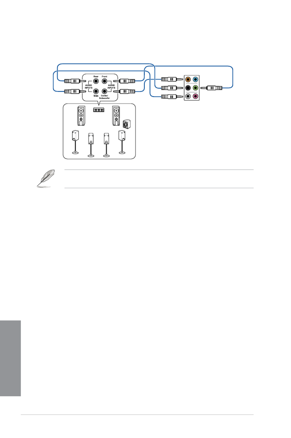
Connect to 7.1 channel Speakers
When the DTS UltraPC II function is enabled, ensure to connect the rear speaker to the
gray port.
2.4 Starting up for the first time
1. After making all the connections, replace the system case cover.
2. Ensure that all switches are off.
3. Connect the power cord to the power connector at the back of the system chassis.
4. Connect the power cord to a power outlet that is equipped with a surge protector.
5. Turnonthedevicesinthefollowingorder:
a. Monitor
b. ExternalSCSIdevices(startingwiththelastdeviceonthechain)
c. System power
6. After applying power, the system power LED on the system front panel case lights up.
For systems with ATX power supplies, the system LED lights up when you press the
ATX power button. If your monitor complies with the “green” standards or if it has a
“power standby” feature, the monitor LED may light up or change from orange to green
after the system LED turns on.
The system then runs the power-on self tests (POST). While the tests are running, the
BIOSbeeps(refertotheBIOSbeepcodestable)oradditionalmessagesappearon
the screen. If you do not see anything within 30 seconds from the time you turned on
the power, the system may have failed a power-on test. Check the jumper settings and
connections or call your retailer for assistance.

Chapter 3
Load Optimized
Defaults Exit <F5> 3.10 Exit Menu
1.2.7 Jumpers
BIOS menu screen
EZ Mode Advanced Mode
Exit Exit/Advanced Mode
3.2 BIOS setup program
Entering BIOS at startup
Entering BIOS Setup after POST
Produktspecifikationer
| Varumärke: | Asus |
| Kategori: | moderkort |
| Modell: | Z97-PRO |
Behöver du hjälp?
Om du behöver hjälp med Asus Z97-PRO ställ en fråga nedan och andra användare kommer att svara dig
moderkort Asus Manualer

8 April 2025
8 April 2025
3 April 2025
3 April 2025
3 April 2025
3 April 2025
2 April 2025
2 April 2025
1 April 2025
27 Mars 2025
moderkort Manualer
- moderkort Sharkoon
- moderkort Gigabyte
- moderkort Asrock
- moderkort Supermicro
- moderkort Evga
- moderkort Intel
- moderkort MSI
- moderkort ECS
- moderkort NZXT
- moderkort Foxconn
- moderkort Advantech
- moderkort Elitegroup
- moderkort EPoX
- moderkort Biostar
Nyaste moderkort Manualer
30 Mars 2025
25 Mars 2025
10 Mars 2025
3 Mars 2025
3 Mars 2025
3 Mars 2025
3 Mars 2025
3 Mars 2025
3 Mars 2025