Botex Dr. RDM I DMX Bruksanvisning
Läs nedan 📖 manual på svenska för Botex Dr. RDM I DMX (80 sidor) i kategorin Lättnad. Denna guide var användbar för 5 personer och betygsatt med 4.5 stjärnor i genomsnitt av 2 användare
Sida 1/80
Dr. RDM I DMX RDM
Tester
controller
User manual

Musikhaus Thomann
Thomann GmbH
Hans-Thomann-Straße 1
96138 Burgebrach
Germany
Telephone: +49 (0) 9546 9223-0
E-mail: info@thomann.de
Internet: www.thomann.de
06.03.2020, ID: 421279 (V2)

Table of contents
1 General information 6.................................................................................................................................
1.1 Further information........................................................................................................................... 7
1.2 Notational conventions.................................................................................................................... 8
1.3 Symbols and signal words............................................................................................................ 10
2 Safety instructions 11..................................................................................................................................
3 Features 13.......................................................................................................................................................
4 Installation and starting up 14................................................................................................................
5 Connections and controls 16...................................................................................................................
6 Operating 19....................................................................................................................................................
6.1 Main menu.......................................................................................................................................... 20
6.2 DMX 512 test...................................................................................................................................... 21
6.3 RDM test.............................................................................................................................................. 35
6.4 MIDI test.............................................................................................................................................. 64
6.5 Cable test............................................................................................................................................ 66
6.6 System settings................................................................................................................................. 69
Table of contents
Dr. RDM I DMX RDM Tester 3
controller

7 Technical 74specications.......................................................................................................................
8 Plug and connection assignment 76....................................................................................................
9 Protecting the environment 77..............................................................................................................
Table of contents
4Dr. RDM I DMX RDM Tester
controller

Dr. RDM I DMX RDM Tester 5
controller

1 General information
This user manual contains important information on the safe operation of the device. Read and
follow all safety notes and all instructions. Save this manual for future reference. Make sure
that it is available to all persons using this device. If you sell the device to another user, be sure
that they also receive this manual.
Our products and user manuals are subject to a process of continuous development. We there‐
fore reserve the right to make changes without notice. Please refer to the latest version of the
user manual which is ready for download under .www.thomann.de
General information
6Dr. RDM I DMX RDM Tester
controller
1.1 Further information
On our website ( you will lots of further information and details on thewww.thomann.de) nd
following points:
Download This manual is also available as PDF for you to download.le
Keyword search Use the search function in the electronic version to the topics ofnd
interest for you quickly.
Online guides Our online guides provide detailed information on technical basics
and terms.
Personal consultation For personal consultation please contact our technical hotline.
Service If you have any problems with the device the customer service will
gladly assist you.
General information
Dr. RDM I DMX RDM Tester 7
controller

1.2 Notational conventions
This manual uses the following notational conventions:
The letterings for connectors and controls are marked by square brackets and italics.
Examples: control, button.[VOLUME] [Mono]
Texts and values displayed on the device are marked by quotation marks and italics.
Examples: , .‘24ch’ ‘OFF’
Letterings
Displays
General information
8Dr. RDM I DMX RDM Tester
controller

The individual steps of an instruction are numbered consecutively. The result of a step is
indented and highlighted by an arrow.
Example:
1. Switch on the device.
2. Press .[Auto]
ðAutomatic operation is started.
3. Switch the device.o
References to other locations in this manual are by an arrow and the pageidentied specied
number. In the electronic version of the manual, you can click the cross-reference to jump to
the location.specied
Example: See
Ä
‘Cross-references’ on page 9.
Instructions
Cross-references
General information
Dr. RDM I DMX RDM Tester 9
controller
1.3 Symbols and signal words
In this section you will an overview of the meaning of symbols and signal words that arend
used in this manual.
Signal word Meaning
DANGER! This combination of symbol and signal word indicates an
immediate dangerous situation that will result in death or
serious injury if it is not avoided.
NOTICE! This combination of symbol and signal word indicates a pos‐
sible dangerous situation that can result in material and
environmental damage if it is not avoided.
Warning signs Type of danger
Warning – danger zone.
General information
10 Dr. RDM I DMX RDM Tester
controller

2 Safety instructions
This device is for testing devices that are controlled via DMX, RDM or MIDI or output these sig‐
nals. Use the device only as described in this user manual. Any other use or use under other
operating conditions is considered to be improper and may result in personal injury or prop‐
erty damage. No liability will be assumed for damages resulting from improper use.
This device may be used only by persons with physical, sensorial, and intellectualsucient
abilities and having corresponding knowledge and experience. Other persons may use this
device only if they are supervised or instructed by a person who is responsible for their safety.
DANGER!
Danger for children
Ensure that plastic bags, packaging, etc. are disposed of properly and are not
within reach of babies and young children. Choking hazard!
Ensure that children do not detach any small parts (e.g. knobs or the like) from
the unit. They could swallow the pieces and choke!
Never let children unattended use electrical devices.
Intended use
Safety
Safety instructions
Dr. RDM I DMX RDM Tester 11
controller
NOTICE!
External power supply
The device is powered by an external power supply. Before connecting the
external power supply, ensure that the input voltage (AC outlet) matches the
voltage rating of the device and that the AC outlet is protected by a residual cur‐
rent circuit breaker. Failure to do so could result in damage to the device and pos‐
sibly the user.
Unplug the external power supply before electrical storms occur and when the
device is unused for long periods of time to reduce the risk of electric shock or
re.
NOTICE!
Operating conditions
This device has been designed for indoor use only. To prevent damage, never
expose the device to any liquid or moisture. Avoid direct sunlight, heavy dirt, and
strong vibrations.
Safety instructions
12 Dr. RDM I DMX RDM Tester
controller

3 Features
nUniversal test device for DMX, RDM and MIDI networks
n5-pin DMX in and output
nMIDI input
nPlug-in power supply and adapter for 3-pin DMX plug included
nOperating via buttons and display on the unit
Features
Dr. RDM I DMX RDM Tester 13
controller

4 Installation and starting up
Unpack and check carefully there is no transportation damage before using the unit. Keep the
equipment packaging. To fully protect the product against vibration, dust and moisture during
transportation or storage use the original packaging or your own packaging material suitable
for transport or storage, respectively.
Create all connections while the device is Use the shortest possible high-quality cables foro.
all connections. Take care when running the cables to prevent tripping hazards.
The included lanyard can be threaded through the bottom of the device.
Only rechargeable NiMH batteries may be used.
The battery compartment is located on the back of the device.
Inserting batteries
Installation and starting up
14 Dr. RDM I DMX RDM Tester
controller

The batteries are not included in the scope of delivery.
1. Loosen the screw of the battery compartment cover using a cross-head screwdriver.
Remove the cover.
2. Insert the batteries (4 × NiMH, AAA, rechargeable) into the battery compartment. Pay
attention to the correct location of the poles.
3. Replace the battery compartment cover. Tighten the cover.
Use the included power adapter for charging the inserted batteries.
Connect the supplied mains adapter to the power supply input of the device and then
plug the adapter into an AC outlet.
ðThe batteries are being charged. The LED lights when the batteries are fully[Normal]
charged.
Charging the batteries
Installation and starting up
Dr. RDM I DMX RDM Tester 15
controller

5 Connections and controls
Connections and controls
16 Dr. RDM I DMX RDM Tester
controller

1 Jog Wheel for control and menu selection
2 Display
The display is turned after an adjustable period of time without keystroke. Press the jog wheel to reactivate theo
display.
3[DMX/RDM OUT]
5-pin DMX / RDM output
4[DMX/RDM IN]
5-pin DMX / RDM input
5[MIDI IN]
MIDI input
6[Power Switch]
Main switch. Turns the device on and o.
7[PWR]
The LED indicates that the device is switched on.
Connections and controls
Dr. RDM I DMX RDM Tester 17
controller
8[Program Update]
Micro SD slot
9[Under Voltage]
This LED lights up when the supply voltage is too low.
10 [Normal]
The LED indicates that the supply voltage is within the permissible range.
11 [DC INPUT]
Connector for the supplied power supply adapter.
Connections and controls
18 Dr. RDM I DMX RDM Tester
controller

6 Operating
The device can be powered by batteries or with the included AC adapter.
Use with batterie: Insert the batteries into the device.
Ä
‘Inserting batteries’ on page 14
Use with power adapter: Connect the supplied mains adapter to the power supply input of the
device and then plug the adapter into an AC outlet.
Operating
Dr. RDM I DMX RDM Tester 19
controller

6.1 Main menu
1. Turn the jog wheel to highlight a menu item.
2. Press the jog wheel to select the highlighted menu item.
3. Press the jog wheel again to open the associated submenu.
4. The display shows the available elements of the submenu.
5. Select the menu item and press the jog wheel to return to the main menu.‘EXIT’
Selection in main menu
Operating
20 Dr. RDM I DMX RDM Tester
controller

6.2 DMX 512 test
This menu allows you to monitor the data packets being received by DMX-controlled devices
or sending test data to the devices.
Operating
Dr. RDM I DMX RDM Tester 21
controller

1. Select the item from the main menu.‘DMX-512 TEST’
2. Press the jog wheel to open the respective submenu.
ðThe display shows:
3. Select one of the submenus , or .‘DMX Packet Test’ ‘DMX Data Receive’ ‘DMX Data Send’
Operating
22 Dr. RDM I DMX RDM Tester
controller
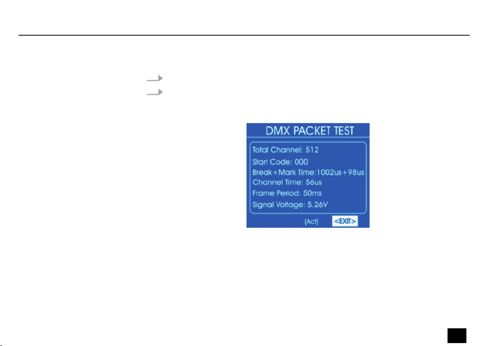
1. Select the item from the submenu .‘DMX Packet Test’ ‘DMX-512 Test’
2. Press the jog wheel to open the respective submenu.
ðIf the wiring is correct and a DMX signal is received, the display shows the following
values:
If no signal is received, the display shows:
DMX packet test
Operating
Dr. RDM I DMX RDM Tester 23
controller

In this case, check the wiring and the correct of the connectors.t
3. To return to the parent menu, select and press the jog wheel to ‘EXIT’ conrm.
Operating
24 Dr. RDM I DMX RDM Tester
controller

1. Select the item from the submenu .‘DMX Data Receive’ ‘DMX-512 Test’
2. Press the jog wheel to open the respective submenu.
ðThe display shows:
It will display the received DMX value ( … ) for every 25 channels.‘000’ ‘255’
3. To change the displayed channel, use the jog wheel to select and press therst ‘Start’
jog wheel. Turn the jog wheel until the number of the desired channel appears at .‘Start’
Press the jog wheel to conrm.
Analysis of received DMX data
Operating
Dr. RDM I DMX RDM Tester 25
controller

4. To change the display format, use the jog wheel to select and press the jog‘Format’
wheel. Turn the jog wheel to select one of the following formats.
n‘DEC’ : Decimal values
n‘PER’ : Percentage values
n‘BAR’ : Bars of squares
n‘RGB’ : Squares with RGB colour mixing
n‘BRG’ : Squares with BGR colour mixing
n‘HEX’ : Hexadecimal values
Press the jog wheel.
5. To return to the parent menu, select and press the jog wheel to ‘EXIT’ conrm.
Operating
26 Dr. RDM I DMX RDM Tester
controller

1. Select the item from the submenu .‘DMX Data Send’ ‘DMX-512 TEST’
2. Press the jog wheel to open the respective submenu.
ðThe display shows:
3. Select the item from the submenu .‘Single Channel Mode’ ‘DMX-512 SEND’
4. Press the jog wheel to open the respective submenu.
ðThe display shows:
Analysis of transmitted DMX
data
Operating
Dr. RDM I DMX RDM Tester 27
controller

5. To select the channel on which the data should be sent, select the item . Press‘Channel’
the jog wheel. Use the jog wheel to set a value between 1 and 512 – or for transmis‐‘All’
sion on all channels.
6. To select an operating mode, select . Press the jog wheel. Use the jog wheel to‘Mode’
select one of the following options:
n‘Fader Only’ : The transmitted DMX value can be adjusted between 0 and 255 with
the jog wheel.
n‘Auto ON/OFF’ : The transmitted DMX value automatically changes at the set speed
n‘Ramping’ : The transmitted DMX value rises evenly with the set speed, then the
process repeats itself
Operating
28 Dr. RDM I DMX RDM Tester
controller

n‘Stop’ : The transmitted DMX value can not be changed
7. To select the value range of the data transmitted, select the item . Press‘Channel Level’
the jog wheel. Use the jog wheel to set a value between 0 and 255.
8. To set the rate of change, select . Press the jog wheel. Use the jog wheel to set a‘Speed’
value between and .‘level 0’ ‘level 10’
9. To return to the parent menu, select and press the jog wheel to ‘EXIT’ conrm.
10. Select the item from the submenu .‘Multiple Channel Mode’ ‘DMX-512 SEND’
11. Press the jog wheel to open the respective submenu.
ðThe display shows:
Operating
Dr. RDM I DMX RDM Tester 29
controller

12. To change the channel for which DMX values are to be sent, use the jog wheel torst
select and press the jog wheel. Turn the jog wheel until the number of‘Start/Channel’
the desired channel appears at . Press the jog wheel to ‘Start’ conrm.
13. To set the transmitted DMX value in the range 0 to 255, select the value with the jogrst
wheel. Press the jog wheel. Set the desired value with the jog wheel. Press the jog wheel.
14. To change the display format, use the jog wheel to select and press the jog‘Format’
wheel. Turn the jog wheel to select one of the following formats.
n‘DEC’ : Decimal values
n‘PER’ : Percentage values
Operating
30 Dr. RDM I DMX RDM Tester
controller

n‘BAR’ : Bars of squares
n‘HEX’ : Hexadecimal values
Press the jog wheel.
15. To reset the transmitted DMX value, use the jog wheel to select the item and‘All Reset’
press the jog wheel.
16. To return to the parent menu, select and press the jog wheel to ‘EXIT’ conrm.
17. Select the item from the submenu .‘Color Demo Mode’ ‘DMX-512 SEND’
18. Press the jog wheel to open the respective submenu.
ðThe display shows:
Operating
Dr. RDM I DMX RDM Tester 31
controller

19. Use the jog wheel to select the setting to be changed and press the jog wheel. Turn the
jog wheel to select or adjust a value. The following table shows the menu items and
choices.
Menu item Choices Meaning
‘Pixel Type’ ‘8Bit’ ‘16Bit’, Resolution of connected devices
‘Start Channel’ ‘1’ ‘512’… First channel for which DMX values are to be sent
‘Master Level’ ‘0’ ‘255’… Maximum DMX value
Operating
32 Dr. RDM I DMX RDM Tester
controller

Menu item Choices Meaning
‘Speed’ ‘Level0’ ‘Level10’… Running speed
‘Fade Time’ ‘0 %’ ‘100 %’… Fade time
20. To return to the parent menu, select and press the jog wheel to ‘EXIT’ conrm.
21. Select the item from the submenu .‘Chase Demo Mode’ ‘DMX-512 SEND’
22. Press the jog wheel to open the respective submenu.
ðThe display shows:
Operating
Dr. RDM I DMX RDM Tester 33
controller

23. Use the jog wheel to select the setting to be changed and press the jog wheel. Turn the
jog wheel to select or adjust a value. The following table shows the menu items and
choices.
Menu item Choices Meaning
‘Start Chan.’ ‘1’ ‘512’… First channel for which DMX values are to be sent
‘Master’ ‘0’ ‘255’… Maximum DMX value
‘Pixel Type’ ‘8Bit’ ‘16Bit’, Resolution of connected devices
‘Total Pixel’ ‘1’ ‘512’… Number of connected devices
‘Pixel Group’ Value within the range of
‘Total Pixel’
Number of devices in a group
‘Jump Pixel’ ‘PixelValue within the range of
Group’
Number of devices that will be switched within the group
‘Test Color’ ‘Color 1’ ‘All’, Number of colours of the spotlight to be tested
‘Speed level’ ‘Level0’ ‘Level10’ ‘Manual’… , Running speed
‘Fade Time’ ‘0 %’ ‘100 %’… Fade time
24. To return to the parent menu, select and press the jog wheel to ‘EXIT’ conrm.
Operating
34 Dr. RDM I DMX RDM Tester
controller

25. To return to the main menu, select again and press the jog wheel to ‘EXIT’ conrm.
6.3 RDM test
This menu allows you to retrieve information about the connected RDM-controlled devices or
send test data to the devices.
Operating
Dr. RDM I DMX RDM Tester 35
controller
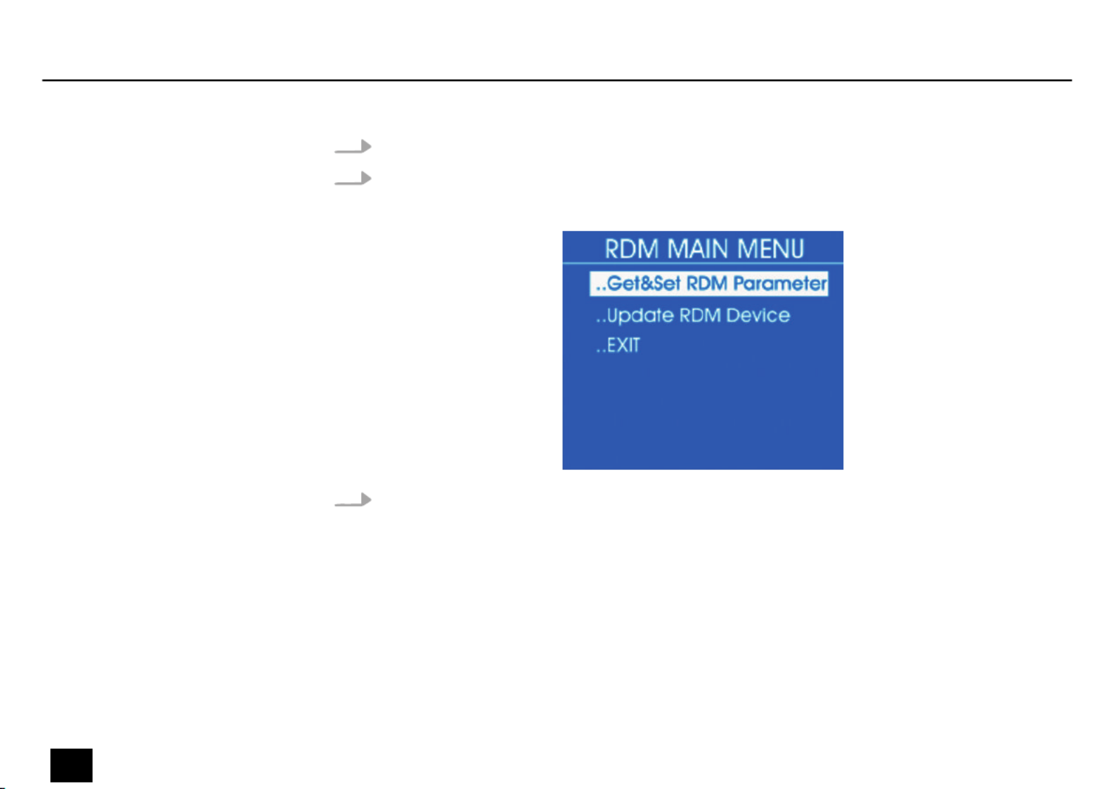
1. Select the item from the main menu.‘RDM DATA TEST’
2. Press the jog wheel to open the respective submenu.
ðThe display shows:
3. Select one of the submenus or .‘Get&Set RDM Parameter’ ‘Update RDM Device’
Operating
36 Dr. RDM I DMX RDM Tester
controller

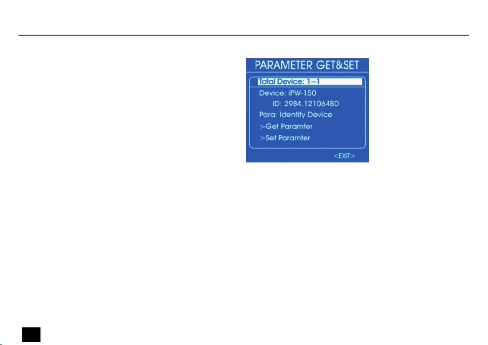
1. Select the item from the submenu .‘Get&Set RDM Parameter’ ‘RDM DATA TEST’
2. Press the jog wheel to open the respective submenu.
ðThe display shows:
If the wiring is correct and an RDM-controlled device is found, the display shows
real-time information about the device:
Retrieve RDM parameters - Iden‐
tify Device
Operating
Dr. RDM I DMX RDM Tester 37
controller
If no signal is received, the display shows:
Operating
38 Dr. RDM I DMX RDM Tester
controller
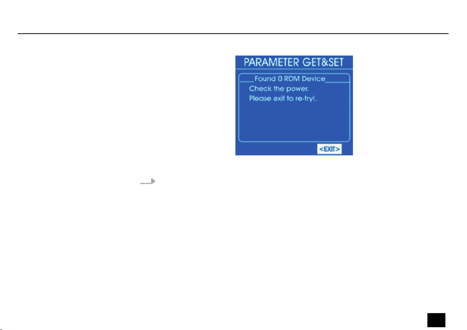
In this case, check the wiring and the correct of the connectors.t
3. For more detailed information, use the jog wheel to select . Press the jog wheel.‘Para’
ðThe display shows:
Operating
Dr. RDM I DMX RDM Tester 39
controller
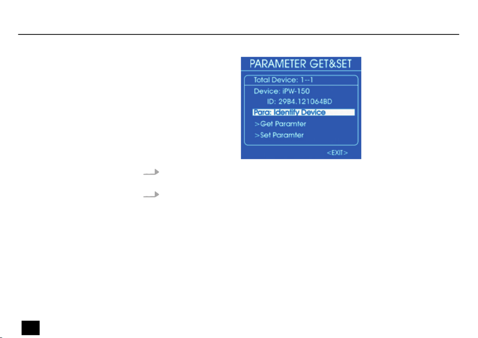
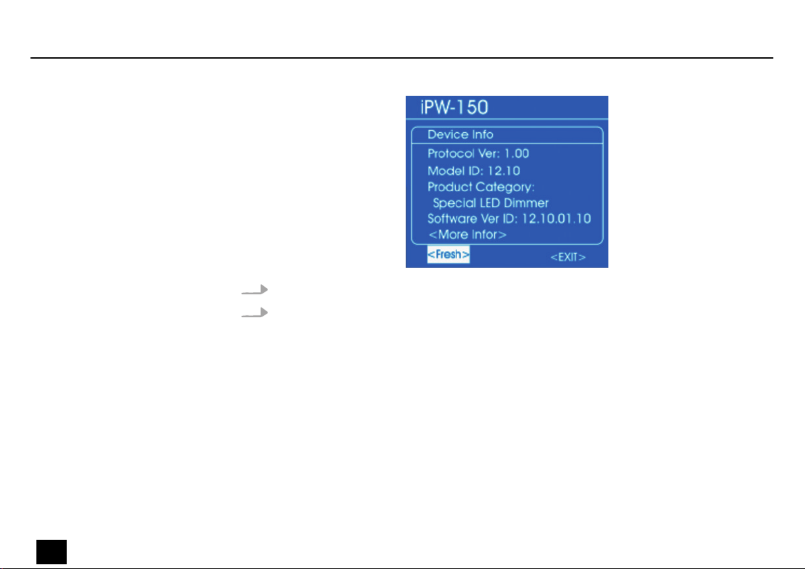
4. The selectable parameters depend on the respective device, examples: ,‘Identify Device’
‘Device Info’ ‘DMX Start Address’, .
5. To retrieve a parameter, select it with the jog wheel and press the jog wheel. Select ‘Get
Parameter’ and press the jog wheel.
ðThe display shows, for example:
Operating
40 Dr. RDM I DMX RDM Tester
controller
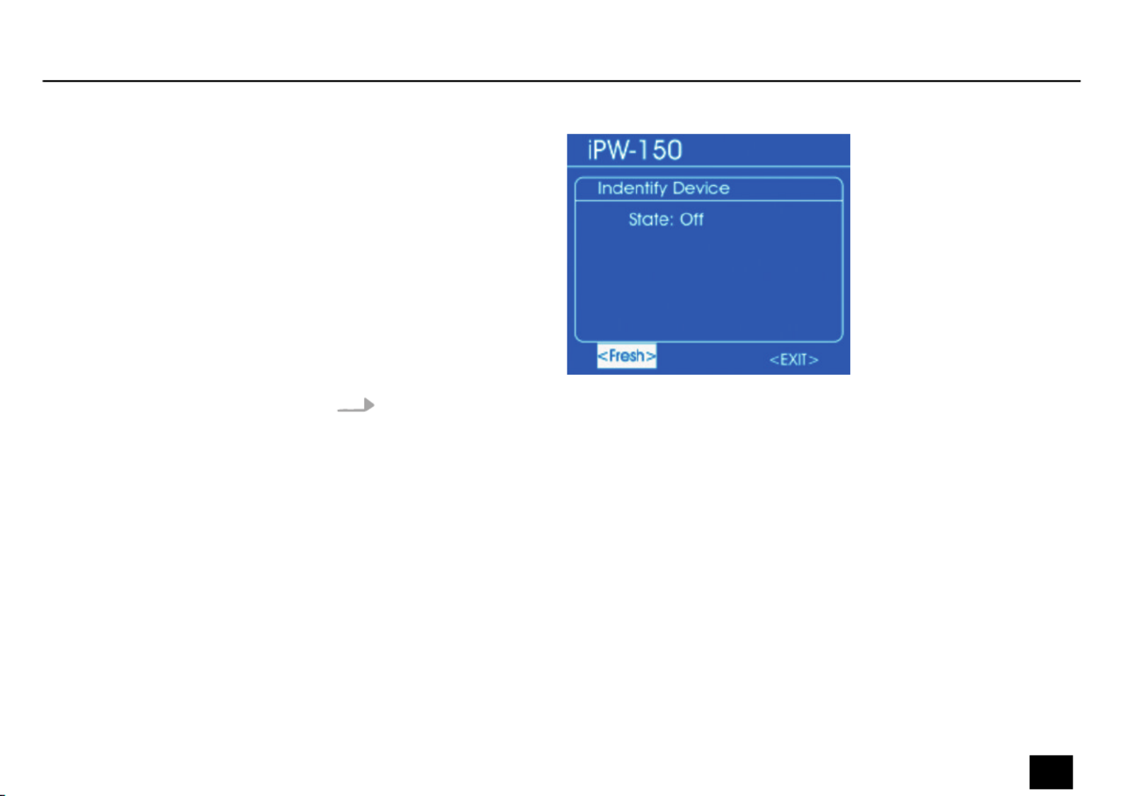
6. Use the jog wheel to select to refresh the displayed information, or to‘Fresh’ ‘EXIT’
return to the parent menu. Press the jog wheel.
Operating
Dr. RDM I DMX RDM Tester 41
controller

1. Select the item from the submenu .‘Get&Set RDM Parameter’ ‘RDM DATA TEST’
2. Press the jog wheel to open the respective submenu.
ðThe display shows:
If the wiring is correct and an RDM-controlled device is found, the display shows
real-time information about the device:
Retrieve RDM Device Informa‐
tion - Device Info
Operating
42 Dr. RDM I DMX RDM Tester
controller

If no signal is received, the display shows:
Operating
Dr. RDM I DMX RDM Tester 43
controller

In this case, check the wiring and the correct of the connectors.t
3. For more detailed information, use the jog wheel to select . Press the jog wheel.‘Para’
ðThe display shows:
Operating
44 Dr. RDM I DMX RDM Tester
controller
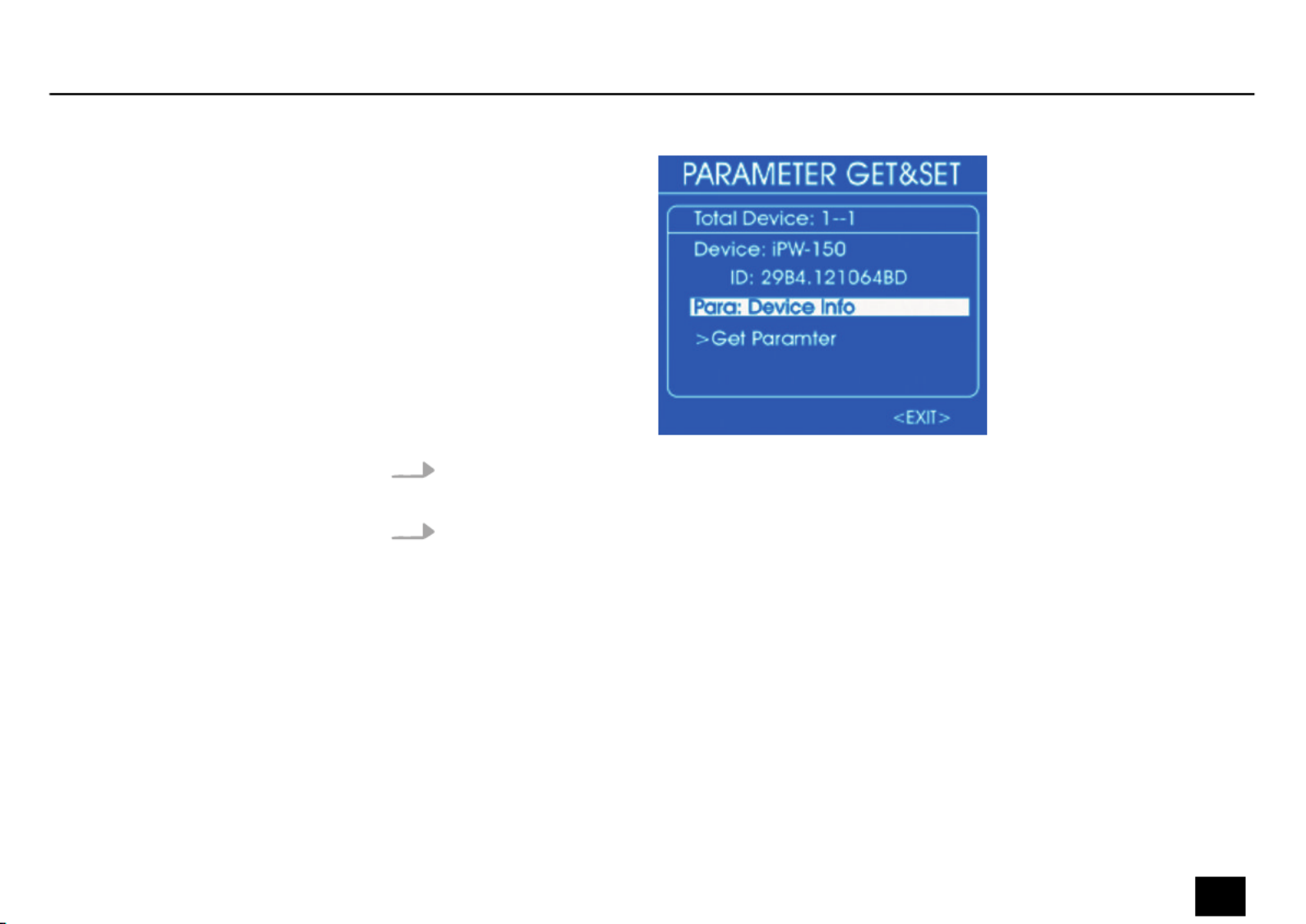
4. The selectable parameters depend on the respective device, examples: ,‘Identify Device’
‘Device Info’ ‘DMX Start Address’, .
5. To retrieve a parameter, select it with the jog wheel and press the jog wheel. Select ‘Get
Parameter’ and press the jog wheel.
ðThe display shows, for example:
Operating
Dr. RDM I DMX RDM Tester 45
controller
6. Use the jog wheel to select to access further parameters.‘More Info’
7. Use the jog wheel to select to refresh the displayed information, or to‘Fresh’ ‘EXIT’
return to the parent menu. Press the jog wheel.
Operating
46 Dr. RDM I DMX RDM Tester
controller
Produktspecifikationer
| Varumärke: | Botex |
| Kategori: | Lättnad |
| Modell: | Dr. RDM I DMX |
Behöver du hjälp?
Om du behöver hjälp med Botex Dr. RDM I DMX ställ en fråga nedan och andra användare kommer att svara dig
Lättnad Botex Manualer

10 September 2024
9 September 2024
9 September 2024
9 September 2024
9 September 2024
8 September 2024
8 September 2024
8 September 2024
8 September 2024
8 September 2024
Lättnad Manualer
- Lättnad Xiaomi
- Lättnad LG
- Lättnad Bosch
- Lättnad IKEA
- Lättnad Philips
- Lättnad DeWalt
- Lättnad Honeywell
- Lättnad JBL
- Lättnad Siemens
- Lättnad Ansmann
- Lättnad Reflecta
- Lättnad Qazqa
- Lättnad ADB
- Lättnad Brennenstuhl
- Lättnad OneConcept
- Lättnad KonstSmide
- Lättnad Workzone
- Lättnad LivarnoLux
- Lättnad Generac
- Lättnad Ozito
- Lättnad Nedis
- Lättnad Gembird
- Lättnad Black And Decker
- Lättnad Tiger
- Lättnad Innoliving
- Lättnad Miomare
- Lättnad Stanley
- Lättnad Crivit
- Lättnad Eglo
- Lättnad Lucide
- Lättnad Caliber
- Lättnad SereneLife
- Lättnad OK
- Lättnad Yato
- Lättnad Dyson
- Lättnad SilverStone
- Lättnad Kichler
- Lättnad Westinghouse
- Lättnad Ryobi
- Lättnad Vivanco
- Lättnad Blaupunkt
- Lättnad Metabo
- Lättnad TP Link
- Lättnad BeamZ
- Lättnad Logik
- Lättnad Medisana
- Lättnad Anslut
- Lättnad Trust
- Lättnad Milwaukee
- Lättnad Hikoki
- Lättnad Elro
- Lättnad Sun Joe
- Lättnad EMOS
- Lättnad Halo
- Lättnad Aukey
- Lättnad KlikaanKlikuit
- Lättnad Gemini
- Lättnad Beper
- Lättnad Denver
- Lättnad Cateye
- Lättnad GLP
- Lättnad Roland
- Lättnad Hazet
- Lättnad Schneider
- Lättnad Hama
- Lättnad Fenix
- Lättnad Maxxmee
- Lättnad Gardena
- Lättnad Theben
- Lättnad Chamberlain
- Lättnad Maginon
- Lättnad Megaman
- Lättnad Dometic
- Lättnad Velleman
- Lättnad Hayward
- Lättnad Varta
- Lättnad Eheim
- Lättnad GlobalTronics
- Lättnad Smartwares
- Lättnad Easymaxx
- Lättnad GoGEN
- Lättnad American DJ
- Lättnad Steren
- Lättnad Perel
- Lättnad Engenius
- Lättnad Audiosonic
- Lättnad Steinel
- Lättnad IFM
- Lättnad Lumie
- Lättnad Livarno
- Lättnad Watshome
- Lättnad Envivo
- Lättnad Auriol
- Lättnad Ardes
- Lättnad Black Diamond
- Lättnad ESYLUX
- Lättnad Melinera
- Lättnad Adj
- Lättnad Biltema
- Lättnad Kathrein
- Lättnad Nitecore
- Lättnad Razer
- Lättnad Mio
- Lättnad GRE
- Lättnad Novy
- Lättnad In Lite
- Lättnad Powerplus
- Lättnad Porter-Cable
- Lättnad Ion
- Lättnad Cotech
- Lättnad Viessmann
- Lättnad Rollei
- Lättnad Peerless-AV
- Lättnad Trotec
- Lättnad DIO
- Lättnad Maul
- Lättnad Sigma
- Lättnad Näve
- Lättnad Behringer
- Lättnad Hive
- Lättnad NGS
- Lättnad Godox
- Lättnad Goobay
- Lättnad Bresser
- Lättnad Olight
- Lättnad Chacon
- Lättnad Astro
- Lättnad Bigben
- Lättnad Massive
- Lättnad Elation
- Lättnad TFA
- Lättnad Yongnuo
- Lättnad Gamma
- Lättnad Laser
- Lättnad Clas Ohlson
- Lättnad Lexon
- Lättnad Powerfix
- Lättnad Steinhauer
- Lättnad CAT
- Lättnad QTX
- Lättnad Zuiver
- Lättnad Reer
- Lättnad Belux
- Lättnad Rademacher
- Lättnad Kress
- Lättnad Busch-Jaeger
- Lättnad EVE
- Lättnad Tesy
- Lättnad Ikan
- Lättnad Chauvet
- Lättnad Mazda
- Lättnad Delta Dore
- Lättnad Blumfeldt
- Lättnad GVM
- Lättnad Omnitronic
- Lättnad Gira
- Lättnad Jung
- Lättnad Harvia
- Lättnad Genaray
- Lättnad Ring
- Lättnad Vivitar
- Lättnad HQ
- Lättnad Max
- Lättnad Be Cool
- Lättnad Fluval
- Lättnad Nanlite
- Lättnad Ecomed
- Lättnad Showtec
- Lättnad Profoto
- Lättnad Trio Lighting
- Lättnad Ranex
- Lättnad Qnect
- Lättnad Conceptronic
- Lättnad Eurolite
- Lättnad Geemarc
- Lättnad Nexa
- Lättnad Bazooka
- Lättnad Wentronic
- Lättnad Peerless
- Lättnad Infinity
- Lättnad NZXT
- Lättnad Dymond
- Lättnad Rocktrail
- Lättnad ILive
- Lättnad Friedland
- Lättnad Nexxt
- Lättnad Bora
- Lättnad Ibiza Sound
- Lättnad Cocraft
- Lättnad Impact
- Lättnad HQ Power
- Lättnad Lume Cube
- Lättnad Stairville
- Lättnad Crestron
- Lättnad Adastra
- Lättnad Litecraft
- Lättnad Nordlux
- Lättnad Garden Lights
- Lättnad Monster
- Lättnad ORNO
- Lättnad Toolcraft
- Lättnad Manfrotto
- Lättnad Pontec
- Lättnad Marklin
- Lättnad Shada
- Lättnad Swisstone
- Lättnad Monacor
- Lättnad Handson
- Lättnad Aputure
- Lättnad Brandson
- Lättnad ARRI
- Lättnad Martin
- Lättnad ColorKey
- Lättnad KS
- Lättnad Dydell
- Lättnad Trump Electronics
- Lättnad Aqara
- Lättnad Verbatim
- Lättnad Osram
- Lättnad Blizzard
- Lättnad SIIG
- Lättnad Panzeri
- Lättnad Moen
- Lättnad Merlin Gerin
- Lättnad Sencys
- Lättnad Levita
- Lättnad Unitec
- Lättnad Duronic
- Lättnad Dorr
- Lättnad Ludeco
- Lättnad Ledlenser
- Lättnad Hortensus
- Lättnad Paulmann
- Lättnad Kern
- Lättnad Heirt
- Lättnad Vimar
- Lättnad Kogan
- Lättnad Lenoxx
- Lättnad Cameo
- Lättnad Kanlux
- Lättnad Woodland Scenics
- Lättnad Maxcom
- Lättnad XQ-Lite
- Lättnad LYYT
- Lättnad GAO
- Lättnad Wetelux
- Lättnad SLV
- Lättnad Sagitter
- Lättnad Digipower
- Lättnad Schwaiger
- Lättnad Handy Century
- Lättnad Solaris
- Lättnad Aqua Signal
- Lättnad V-Tac
- Lättnad Century
- Lättnad Esotec
- Lättnad Fuzzix
- Lättnad Mtx Audio
- Lättnad Berger & Schröter
- Lättnad Lideka
- Lättnad Lutec
- Lättnad Maxxworld
- Lättnad SolarlampKoning
- Lättnad Ibiza Light
- Lättnad IXL
- Lättnad Fun Generation
- Lättnad Karma
- Lättnad Meipos
- Lättnad Livarno Lux
- Lättnad Mr. Beams
- Lättnad Knog
- Lättnad Media-tech
- Lättnad Neewer
- Lättnad Pegasi
- Lättnad Mellert SLT
- Lättnad 4K5
- Lättnad Lightway
- Lättnad IMG Stage Line
- Lättnad Wireless Solution
- Lättnad Eutrac
- Lättnad EtiamPro
- Lättnad Olymp
- Lättnad NUVO
- Lättnad Futurelight
- Lättnad LightZone
- Lättnad Varytec
- Lättnad Brilliant
- Lättnad Heitronic
- Lättnad NEO Tools
- Lättnad Govee
- Lättnad Tractel
- Lättnad Enerdan
- Lättnad Luxform Lighting
- Lättnad Canarm
- Lättnad Angler
- Lättnad GP
- Lättnad Klein Tools
- Lättnad Luxform
- Lättnad Karwei
- Lättnad DistriCover
- Lättnad Ideen Welt
- Lättnad Blumill
- Lättnad Vintec
- Lättnad Aquatica
- Lättnad Ledar
- Lättnad Delock Lighting
- Lättnad LightPro
- Lättnad FlinQ
- Lättnad Adviti
- Lättnad 9.solutions
- Lättnad Pauleen
- Lättnad Obsidian
- Lättnad FeinTech
- Lättnad Gumax
- Lättnad Doughty
- Lättnad Sharper Image
- Lättnad CIVILIGHT
- Lättnad ActiveJet
- Lättnad Enlite
- Lättnad Gingko
- Lättnad Outspot
- Lättnad Innr
- Lättnad Fristom
- Lättnad Dracast
- Lättnad Raya
- Lättnad DTS
- Lättnad Expolite
- Lättnad LSC Smart Connect
- Lättnad Mr Safe
- Lättnad Swisson
- Lättnad Tellur
- Lättnad SSV Works
- Lättnad Chrome-Q
- Lättnad Rotolight
- Lättnad ETC
- Lättnad SWIT
- Lättnad Meteor
- Lättnad Maxim
- Lättnad COLBOR
- Lättnad Megatron
- Lättnad MeLiTec
- Lättnad Integral LED
- Lättnad Time 2
- Lättnad Wachsmuth - Krogmann
- Lättnad Amaran
- Lättnad Dynamax
- Lättnad DreamLED
- Lättnad Beghelli
- Lättnad Casalux
- Lättnad Briloner
- Lättnad Retlux
- Lättnad Adam Hall
- Lättnad Hoftronic
- Lättnad FIAP
- Lättnad Underwater Kinetics
- Lättnad Musicmate
- Lättnad SmallRig
- Lättnad Light4Me
- Lättnad Lowel
- Lättnad Illuminex
- Lättnad Sonoff
- Lättnad Lirio By Philips
- Lättnad Raytec
- Lättnad Gewiss
- Lättnad Hella Marine
- Lättnad Bright Spark
- Lättnad Zero 88
- Lättnad Sengled
- Lättnad Enttec
- Lättnad Ledino
- Lättnad Ikelite
- Lättnad Audibax
- Lättnad Middle Atlantic
- Lättnad Sonlux
- Lättnad Atmospheres
- Lättnad Dainolite
- Lättnad DOTLUX
- Lättnad Ape Labs
- Lättnad Insatech
- Lättnad GEV
- Lättnad JMAZ Lighting
- Lättnad Kinotehnik
- Lättnad Litegear
- Lättnad Busch + Müller
- Lättnad Kino Flo
- Lättnad DCW
- Lättnad LumenRadio
- Lättnad Artecta
- Lättnad DMT
- Lättnad HERA
- Lättnad BB&S
- Lättnad Intellytech
- Lättnad Astera
- Lättnad Temde
- Lättnad Excello
- Lättnad Varaluz
- Lättnad Aveo Engineering
- Lättnad AD Trend
- Lättnad Prolycht
- Lättnad Magmatic
- Lättnad DeSisti
- Lättnad Cineo
- Lättnad Zylight
- Lättnad Smith-Victor
- Lättnad Light & Motion
- Lättnad LUPO
- Lättnad CSL
- Lättnad Altman
- Lättnad EXO
- Lättnad Setti+
- Lättnad Portman
- Lättnad Fotodiox
- Lättnad Claypaky
- Lättnad Blackburn
- Lättnad Bearware
- Lättnad Perfect Christmans
- Lättnad Fiilex
- Lättnad Litepanels
- Lättnad Rosco
- Lättnad Aplic
- Lättnad Rayzr 7
- Lättnad City Theatrical
- Lättnad ET2
- Lättnad Quoizel
- Lättnad WAC Lighting
- Lättnad Golden Lighting
- Lättnad Weeylite
- Lättnad Crystorama
- Lättnad Valerie Objects
- Lättnad OttLite
- Lättnad Sonneman
- Lättnad AFX
- Lättnad Stamos
- Lättnad Yamazen
- Lättnad Elan
- Lättnad Currey & Company
- Lättnad Wiesenfield
- Lättnad Luxli
- Lättnad Livex Lighting
- Lättnad Hinkley Lighting
- Lättnad Sea&Sea
- Lättnad Triton Blue
- Lättnad Singercon
- Lättnad Hudson Valley
- Lättnad Forte Lighting
- Lättnad Craftmade
- Lättnad Quasar Science
- Lättnad Kuzco
- Lättnad Schonbek
Nyaste Lättnad Manualer
8 April 2025
8 April 2025
8 April 2025
7 April 2025
5 April 2025
5 April 2025
5 April 2025
5 April 2025
5 April 2025
5 April 2025