Dahua Technology Pro IPC-HDPW5241G-Z Bruksanvisning
Dahua Technology
övervakningskamera
Pro IPC-HDPW5241G-Z
Läs nedan 📖 manual på svenska för Dahua Technology Pro IPC-HDPW5241G-Z (194 sidor) i kategorin övervakningskamera. Denna guide var användbar för 3 personer och betygsatt med 4.5 stjärnor i genomsnitt av 2 användare
Sida 1/194

Network Camera Web 3.0
Operation Manual
V2.0.0
ZHEJIANG DAHUA VISION TECHNOLOGY CO., LTD.
Foreword I
Foreword
General
This manual introduces the functions, basic configuration, general operation, configuration,
installation and system maintenance of network camera.
Safety Instructions
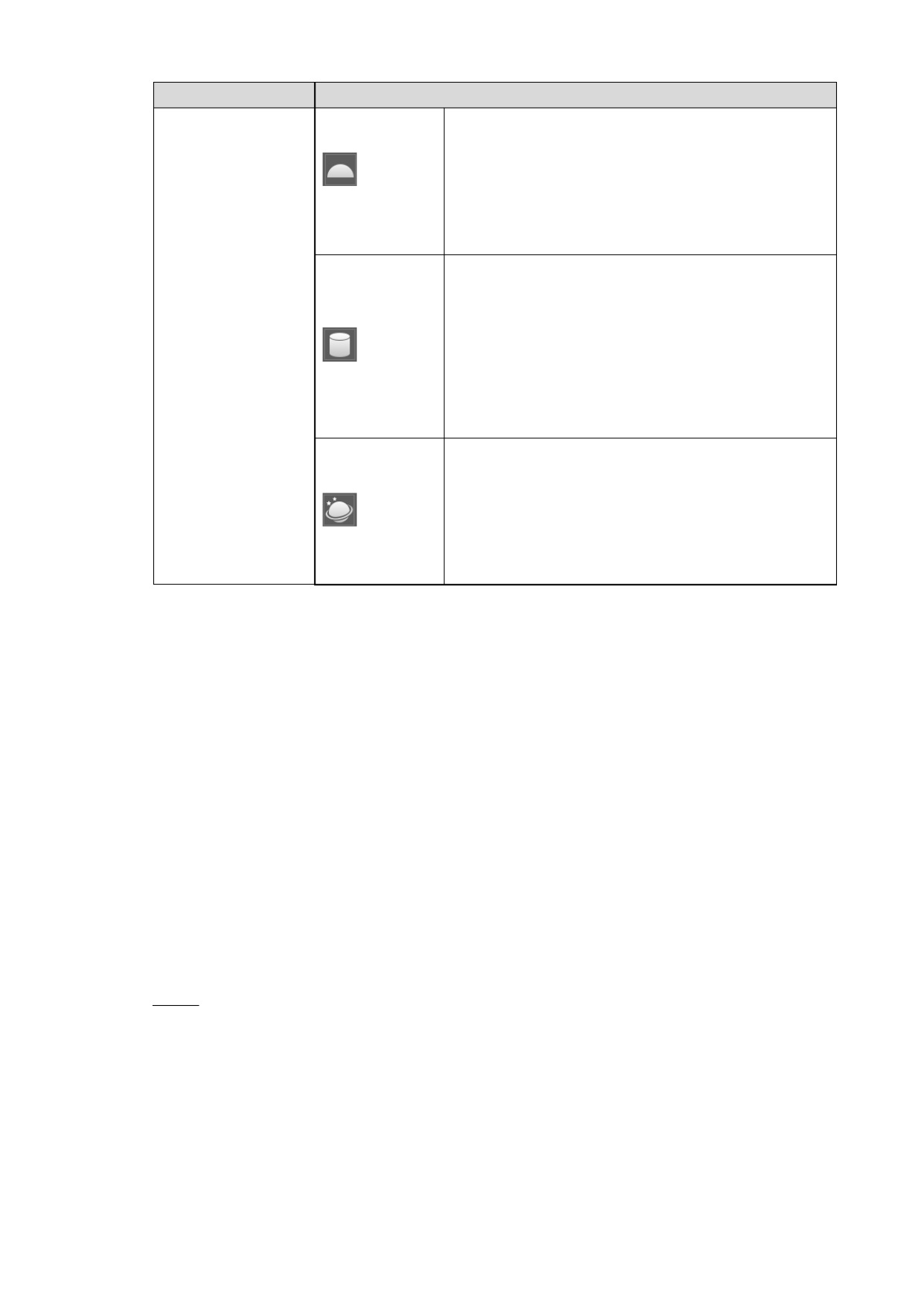
The following categorized signal words with defined meaning might appear in the manual.
Signal Words
Meaning
Indicates a medium or low potential hazard which, if not avoided,
could result in slight or moderate injury.
Indicates a potential risk which, if not avoided, may result in
property damage, data loss, lower performance, or unpredictable
result.
Provides methods to help you solve a problem or save you time.
Provides additional information as the emphasis and supplement
to the text.
Revision History
Version
Revision Content
Release Date
V2.0.0
1. and add Consolidate the outline, baseline and
safety contents, some intelligent functions and
such as face recognition and ANPR.
2. Delete some old function such as stereo vision.
July 2019
V1.0.4
1. Update the chapters of "People Counting" and
"Heat Map" function.
2. Add VR mode of Fisheye device.
3. Add video structuralization function.
March 2019
V1.0.3
Add Stereo Analysis function.
November 2018
V1.0.2
1. Add chapters of "Initialization" and "Stereo
vision."
2. Update the chapters of "Account", "Profile
Management" and "SNMP."
October 2017
V1.0.1
First release.
September 2016

Foreword II
Privacy Protection Notice
As the device user or data controller, you might collect personal data of others such as face,
fingerprints, car plate number, Email address, phone number, GPS and so on. You need to be
in compliance with the local privacy protection laws and regulations to protect the legitimate
rights and interests of other people by implementing measures include but not limited to:
providing clear and visible identification to inform data subject the existence of surveillance
area and providing related contact.
About the Manual
The manual is for reference only. If there is inconsistency between the manual and the
actual product, the actual product shall prevail.
We are not liable for any loss caused by the operations that do not comply with the manual.
The manual would be updated according to the latest laws and regulations of related
regions. For detailed information, see the paper manual, CD-ROM, QR code or our official
website. If there is inconsistency between paper manual and the electronic version, the
electronic version shall prevail.
All the designs and software are subject to change without prior written notice. The product
updates might cause some differences between the actual product and the manual. Please
contact the customer service for the latest program and supplementary documentation.
There still might be deviation in technical data, functions and operations description, or
errors in print. If there is any doubt or dispute, please refer to our final explanation.
Upgrade the reader software or try other mainstream reader software if the manual (in PDF
format) cannot be opened.
All trademarks, registered trademarks and the company names in the manual are the
properties of their respective owners.
Please visit our website, contact the supplier or customer service if there is any problem
occurred when using the device.
If there is any uncertainty or controversy, please refer to our final explanation.

Important Safeguards and Warnings III
Important Safeguards and Warnings
Electrical safety
All installation and operation should conform to your local electrical safety codes.
The power source shall conform to the Safety Extra Low Voltage (SELV) standard, and
supply power with rated voltage which conforms to Limited power Source requirement
according to IEC60950-1. Please Description that the power supply requirement is subject
to the device label.
Make sure the power supply is correct before operating the device.
A readily accessible disconnect device shall be incorporated in the building installation
wiring.
Prevent the power cable from being trampled or pressed, especially the plug, power socket
and the junction extruded from the device.
Environment
Do not aim the device at strong light to focus, such as lamp light and sun light; otherwise it
might cause over brightness or light marks, which are not the device malfunction, and
affect the longevity of Complementary Metal-Oxide Semiconductor (CMOS).
Do not place the device in a damp or dusty environment, extremely hot or cold
temperatures, or the locations with strong electromagnetic radiation or unstable lighting.
Keep the device away from liquid to avoid damage to the internal components. any
Keep the indoor device away from rain or damp to avoid fire or lightning.
Keep sound ventilation to avoid heat accumulation.
Transport, use and store the device within the range of allowed humidity and temperature.
Heavy stress, violent vibration or water splash are not allowed during transportation,
storage and installation.
Pack the device with standard factory packaging or the equivalent material when
transporting the device.
Install the device in the location where only the professional staff with relevant knowledge
of safety guards and warnings can access The accidental injury might happen to the .
non-professionals who enter the installation area when the device is operating normally.
Operation and Daily Maintenance
Do not touch the heat dissipation component of the device to avoid scald.
Carefully follow the instructions in the manual when performing any disassembly operation
about the device; otherwise, it might cause water leakage or poor image quality due to
unprofessional disassemble. Please contact after-sale service for desiccant replacement if
there is condensed fog found on the lens after unpacking or when the desiccant turns
green. (Not all models are included with the desiccant).
It is recommended to use the device together with lightning arrester to improve lightning

Important Safeguards and Warnings IV
protection effect.
It is recommended connect the grounding hole to the ground to enhance the reliability of
the device.
Do not touch the image sensor (CMOS) directly. Dust and dirt could be removed with air
blower, or you can wipe the lens gently with soft cloth that moistened with alcohol.
Device body can be cleaned with soft dry cloth, which can also be used to remove
stubborn stains when moistened with mild detergent. To avoid possible damage on device
body coating which could cause performance decrease, do not use volatile solvent such as
alcohol, benzene, diluent and so on to clean the device body, nor can strong, abrasive
detergent be used.
Dome cover is an optical component, do not touch or wipe the cover with your hands
directly during installation or operation. For removing dust, grease or fingerprints, wipe
gently with moisten oil-free cotton with diethyl or moisten soft cloth. You can also air blower
to remove dust.
Please strengthen the protection of network, device data and personal information by
adopting measures which include but not limited to using strong password, modifying
password regularly, upgrading firmware to the latest version, olating computer and is
network. For some device with old firmware versions, the ONVIF password will not be
modified automatically along with the modification of the system password, and you need
to upgrade the firmware or manually update the ONVIF password.
Use standard components or accessories provided by manufacturer and make sure the
device is installed and maintained by professional engineers.
The surface of the image sensor should not be exposed to laser beam radiation in an
environment where a laser beam device is used.
Do not provide two or more power supply sources for the device unless otherwise specified.
A failure to follow this instruction might cause damage to the device.

Table of Contents V
Table of Contents
Foreword .................................................................................................................................................... I
Important Safeguards and Warnings .................................................................................................... III
1 Overview ................................................................................................................................................. 1
Introduction ................................................................................................................................... 1 1.1
Network Connection ...................................................................................................................... 1 1.2
Function ........................................................................................................................................ 1 1.3
1.3.1 Basic Function .................................................................................................................... 1
1.3.2 Intelligent Function .............................................................................................................. 2
2 Configuration Flow ................................................................................................................................ 5
3 Device Initialization ............................................................................................................................... 6
4 Basic Configuration .............................................................................................................................. 9
Login .............................................................................................................................................. 9 4.1
Live.............................................................................................................................................. 10 4.2
4.2.1 Live Interface .................................................................................................................... 10
4.2.2 Encode bar ........................................................................................................................11
4.2.3 Live view Function Bar ..................................................................................................... 12
4.2.4 Window Adjustment Bar ................................................................................................... 14
PTZ Operation ............................................................................................................................. 20 4.3
4.3.1 Configuring External PTZ Protocol ................................................................................... 20
4.3.2 Configuring PTZ Function ................................................................................................. 21
4.3.3 Calling PTZ ....................................................................................................................... 31
Playback ...................................................................................................................................... 34 4.4
4.4.1 Playback Interface ............................................................................................................ 34
4.4.2 Playing back Video or Picture ........................................................................................... 37
4.4.3 Clipping Video ................................................................................................................... 39
4.4.4 Downloading Video or Picture .......................................................................................... 40
Camera........................................................................................................................................ 41 4.5
4.5.1 Conditions ......................................................................................................................... 41
4.5.2 Setting Video Parameters ................................................................................................. 53
4.5.3 Audio ................................................................................................................................. 67
Network ....................................................................................................................................... 69 4.6
4.6.1 TCP/IP .............................................................................................................................. 70
4.6.2 Port ................................................................................................................................... 71
4.6.3 PPPoE .............................................................................................................................. 73
4.6.4 DDNS ................................................................................................................................ 74
4.6.5 SMTP (Email) .................................................................................................................... 75
4.6.6 UPnP ................................................................................................................................. 77
4.6.7 SNMP ................................................................................................................................ 78
4.6.8 Bonjour .............................................................................................................................. 80
4.6.9 Multicast ............................................................................................................................ 81
4.6.10 802.1x ............................................................................................................................. 82

Table of Contents VI
4.6.11 QoS ................................................................................................................................. 82
4.6.12 Access Platform .............................................................................................................. 83
Storage ........................................................................................................................................ 85 4.7
4.7.1 Schedule ........................................................................................................................... 85
4.7.2 Destination ........................................................................................................................ 86
System ........................................................................................................................................ 89 4.8
4.8.1 General ............................................................................................................................. 89
4.8.2 Date & Time ...................................................................................................................... 90
4.8.3 Splicing ............................................................................................................................. 91
4.8.4 Account ............................................................................................................................. 92
4.8.5 Safety ................................................................................................................................ 99
4.8.6 Peripheral ........................................................................................................................ 106
5 Event ................................................................................................................................................... 110
Setting Alarm Linkage ................................................................................................................110 5.1
5.1.1 Alarm Linkage ..................................................................................................................110
5.1.2 Subscribing Alarm ............................................................................................................116
Setting Smart Track 118 5.2 ...................................................................................................................
5.2.1 Setting Calibration Parameters for Smart Track ..............................................................118
5.2.2 Enabling Alarm Track .......................................................................................................119
Setting Panoramic Calibration .................................................................................................. 121 5.3
Setting Video Detection ............................................................................................................ 122 5.4
5.4.1 Setting Motion Detection ................................................................................................ 122
5.4.2 Setting Video Tamper ..................................................................................................... 124
5.4.3 Setting Scene Changing ................................................................................................. 125
Setting Audio Detection ............................................................................................................. 125 5.5
Setting Smart Plan .................................................................................................................... 126 5.6
Setting IVS Analysis .................................................................................................................. 127 5.7
5.7.1 Global Configuration ....................................................................................................... 128
5.7.2 Rule Configuration .......................................................................................................... 130
Setting Crowd Map ................................................................................................................... 134 5.8
5.8.1 Global Configuration ....................................................................................................... 134
5.8.2 Rule Configuration .......................................................................................................... 135
Setting Face Recognition .......................................................................................................... 138 5.9
5.9.2 Setting Face Detection ................................................................................................... 138
5.9.3 Setting Face Database ................................................................................................... 140
5.9.4 Setting Face Recognition Alarm Linkage ....................................................................... 147
5.9.5 Viewing Face Recognition Result ................................................................................... 148
Setting Face Detection ............................................................................................................ 150 5.10
Setting People Counting ......................................................................................................... 153 5.11
5.11.1 People Counting ........................................................................................................... 153
5.11.2 Viewing People Counting Report .................................................................................. 155
Setting Heat Map .................................................................................................................... 156 5.12
5.12.1 Heat Map ...................................................................................................................... 156
5.12.2 Viewing Heat Map Report ............................................................................................. 157
Setting Stereo Analysis ........................................................................................................... 157 5.13
5.13.1 Setting Rules for Stereo Analysis ................................................................................. 157
5.13.2 Calibration Configuration .............................................................................................. 160

Table of Contents VII
Setting ANPR .......................................................................................................................... 161 5.14
5.14.1 Scene Configuration ..................................................................................................... 162
5.14.2 Setting Picture Overlay ................................................................................................. 164
5.14.3 Viewing ANPR Report ................................................................................................... 165
Setting Video Structralization .................................................................................................. 166 5.15
5.15.1 Scene Configuration ..................................................................................................... 166
5.15.2 Setting Picture Information ........................................................................................... 168
5.15.3 Viewing Video Structralization Report .......................................................................... 169
Setting Relay-in ....................................................................................................................... 1 5.16 70
Setting Abnormality ................................................................................................................. 170 5.17
5.17.1 Setting SD Card ............................................................................................................ 171
5.17.2 Setting Network ............................................................................................................ 171
5.17.3 Setting Illegal Access .................................................................................................... 172
5.17.4 Setting Voltage Detection ............................................................................................. 173
5.17.5 Setting Security Exception ............................................................................................ 173
6 Maintenance ....................................................................................................................................... 175
Requirements ............................................................................................................................ 175 6.1
Auto Maintain ............................................................................................................................ 175 6.2
Resetting Password .................................................................................................................. 176 6.3
Backup and Default ................................................................................................................... 178 6.4
6.4.1 Import/Export .................................................................................................................. 178
6.4.2 Default ............................................................................................................................. 179
Upgrade .................................................................................................................................... 179 6.5
Information ................................................................................................................................ 180 6.6
6.6.1 Version ............................................................................................................................ 180
6.6.2 Log .................................................................................................................................. 180
6.6.3 Remote Log .................................................................................................................... 181
6.6.4 Online User ..................................................................................................................... 182
Cybersecurity Recommendations ................................................................................. 183 Appendix 1

Overview 1
1 Overview
Introduction 1.1
IP camera (Internet Protocol camera), is a type of digital video camera that receives control
data and sends image data through internet. They are commonly used for surveillance,
requiring no local recording device, but only a local network.
IP camera is divided in to single-channel camera and multi- channel camera according to the
channel quantity. For multi- channel camera, you can set the parameters for each channel.
Network Connection 1.2
The common IPC network is connecting IPC and PC through network switch or router. See
Figure 1-1.
Common IPC network Figure 1-1
Get IP address by searching on ConfigTool, and then you can start accessing IPC through
network.
Function 1.3
Functions might vary with different devices, and the actual product shall prevail.
1.3.1 Basic Function
Real-time Monitoring
Live view
When live viewing the image, you can enable audio, voice talk and connect monitoring
center for quick processing on the abnormality.
Adjust the image to the proper position by PTZ.
Snapshot and triple snapshot abnormality of the monitoring image for subsequent view
and processing.
Record abnormality of monitoring image for subsequent view and processing.
Configure coding parameters, and adjust live view image.

Overview 2
Record
Auto record as schedule.
Play back record and picture to view the necessary record or picture.
Download record and picture to be judgment basis.
Alarm linked record.
Account
Add, modify and delete user group, manage user authorities according to user group. and
Add, modify and delete user, configure user authorities. and
Modify user password.
1.3.2 Intelligent Function
Alarm
Set alarm prompt mode and tone according to alarm type.
View alarm prompt message.
Smart Track
Smart track and alarm track.
Switch between smart track and speed dome auto track.
Video Detection
Motion detection, video tampering detection and scene changing detection.
When alarm is triggered, the system links record, alarm output, sending email, PTZ
operation, snapshot and so on. and
Audio Detection
Audio input abnormal detection and intensity change detection.
When alarm is triggered, the system links record, alarm output, sending email, PTZ
operation, snapshot and so on. and
IVS
Cross fence, tripwire, intrusion, abandoned object, moving object, fast moving, parking
detection, people gathering, and loitering detection.
When alarm is triggered, the system links record, alarm output, sending email, PTZ
operation, snapshot and so on. and

Overview 3
Crowd Map
View crowd distribution in real time for the timely arm to avoid accidents like stampede.
When alarm is triggered, the system links record, alarm output, sending email, PTZ
operation, snapshot and so on. and
Face Detection
Detection face and display the related attributes on live interface.
When alarm is triggered, the system links record, alarm output, sending email, PTZ
operation, snapshot and so on. and
Face Recognition
After detecting face, make comparison between the detected face with the face in face
database activates alarm output. , and
Query the recognition result.
People Counting
Count the people flow in/out the detection area, and output report.
When alarm is triggered, the system links record, alarm output, sending email, PTZ
operation, snapshot and so on. and
Heat Map
Count cumulative density of moving objects.
View report of heat map.
Stereo Analysis
Include fall detection, violence detection, people No. error, people approaching detection,
and strand detection.
When alarm is triggered, the system links record, alarm output, sending email, PTZ
operation, snapshot and so on. and
ANPR
Recognize plate number in detection area, and display the related information on live
interface.
When alarm is triggered, the system links alarm output snapshot. and
Video Structur ization al
Snap people, non-motor vehicle and vehicle, and display the related information on the live
interface.

Overview 4
When alarm is triggered, the system links alarm output.
Alarm Setting
When external alarm input device generates alarm, the alarm is triggered.
When alarm is triggered, the system links record, alarm output, sending email, PTZ
operation, snapshot and so on. and
Abnormality
SD card error, network disconnection, illegal access and voltage detection.
When SD card error or illegal access is triggered, the system links alarm output and
sending email.
When network disconnection alarm is triggered, the system links record and alarm output.
When the input voltage is more or less than the rated voltage, the alarm is triggered and
the system links sending email.

Configuration Flow 5
2 Configuration Flow
For the device configuration flow, see Figure 2-1. For details, see Table 2-1. Configure the device
according to the actual situation.
Configuration flow Figure 2-1
Table 2-1 Description of flow
Configuration
Description
Reference
Login
Open IE browser and enter IP
address to login to web interface,
The devices IP address is
192.168.1.108 by default.
4.1 Login
Initialization
Initialize device when you use the
device for the first time.
3 Device Initialization
Basic
parameters
IP address
Modify IP address according to
network planning for the first use
or during network adjustment.
4.6.1 TCP/IP
Date & time
Set date & time to ensure the
record time is correct.
4.8.2 Date & Time
Image
parameters
Adjust image parameters
according to the actual situation to
ensure the image quality.
4.5.1 Conditions
Intelligent
Event
Detection
rules
Configure the necessary detection
rules, including video detection
and IVS and so on.
5 Event
Subscribe
alarm
Subscribe alarm event. When the
subscribed alarm is triggered, the
system will record the alarm on
alarm tab.
5.1.2 Subscribing
Alarm

Device Initialization 6
3 Device Initialization
Device initialization is required for first-time use. This manual is based on the operation the on
web interface. You can also initialize device with ConfigTool, NVR, or platform devices.
Before first login, you need to set the password for admin account to proceed.
To ensure device safety, please keep the password properly after initialization and change
the password regularly.
When initializing device, keep the PC IP and device IP in a same network.
Open IE browser, enter the IP address of the device in the address bar, and then press Step 1
Enter.
The Device Initialization interface is displayed, see Figure 3-1.
The IP is 192.168.1.108 by default.
Device initialization Figure 3-1
Set the password for admin account. For details, see Table 3-1. Step 2
Table 3-1 Description of password configuration
Parameter
Description
User name
The default user name is admi n.
Password
The password must consist of 8 to 32 digits and at least two forms from
number, letter, and common symbols (except "'","",";",":","&") Set a high .
security level password according to the password security notice.
Confirm
password
email
Enter an email address for password reset, and this option is selected
by default.
When you need to reset the password of the admin account, there will
be a security code sent to the rserved email address which can be used
to reset the password.
Click . Step 3 Save

Device Initialization 7
The End-User License Agreement interface is displayed, see Figure 3-2.
End-user license agreement Figure 3-2
Select the check box I have read and agree to all terms, and then click Next. Step 4
The Easy4ip interface is displayed ee Figure 3-3. , s
Easy4ip Figure 3-3
You can now register your device to Easy4ip, select the option if you need it, and then Step 5
click . Next
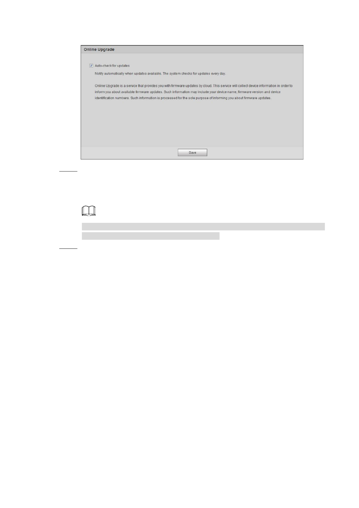
The Online Upgrade interface is displayed, see Figure 3-4.
Device Initialization 8
Online upgrade Figure 3-4
Select the upgrading method as needed. Step 6
If you select Auto-check for updates, the system checks new version once a day
automatically. There will be system notice interface and on Upgrade Version interface
if any new version is available.
Select Setting > System > Upgrade > Online Upgrade, you can also configure this
function on Online Upgrade interface after logi n.
Click . Step 7 Save
Device initialization is completed.
Basic Configuration 9
4 Basic Configuration
Login 4.1
This section introduces how to log in and log out of web interface, and the content is based on
IE Explorer 9.
You need to initialize the device first to log in web interface.
You need to install plug-in for the first login, follow the instruction to download and install.
When initializing device, keep the PC IP and device IP in a same network.
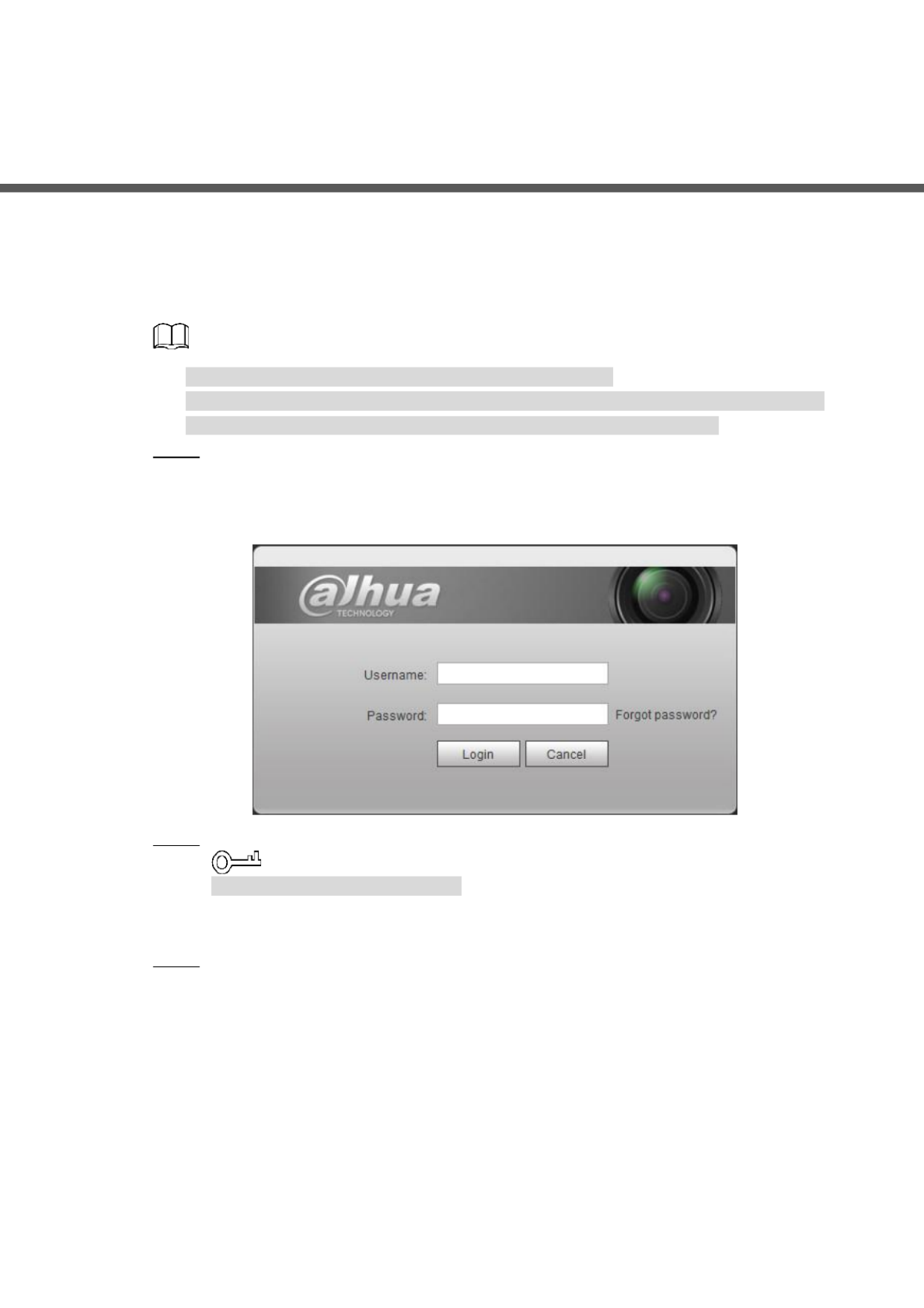
Open IE browser, enter the IP address of the device (192.168.1.108 by default) in the Step 1
address bar and press Enter.
The login interface is displayed. S Figure 4-1. ee
Login Figure 4-1
Enter the username and password. Step 2
The username is admin by default.
Click , and you can reset the password through the email address Forget password?
set during initialization. For details, see "6.3 Resetting Password ."
Click . Step 3 Login
The interface is displayed, see Figure 4-2. Live
Live: Click Live, and you can view the real-time monitoring image.
Playback: Click Playback, and you can play back or download record/image files.
Setting: Click , and you can set the basic and intelligent functions of the Setting
device.
For the device with multiple channels, through selecting channel numbers, you
can set the parameters of the channels.
Alarm: Click you can subscribe and view alarm information. Alarm, and
Logout: Click to return to login interface. Logout
The system will sleep automatically after idling for a period of time.

Basic Configuration 10
Live Figure 4-2
Live 4.2
This section introduces the layout of the interface and function configuration.
4.2.1 Live Interface
This section introduces system menu, encode bar, live view function bar, and window
adjustment bar.
Log in and click tab, the interface is displayed. SLive Live ee Figure 4-3. For the layout details,
see Table 4-1.
The functions and interfaces of different devices might vary, and the actual product shall
prevail.

Basic Configuration 11
Live Figure 4-3
Table 4-1 Description function bar description of
No.
Function
Description
1
Encode bar
Sets stream type and protocol:
2
Live view
Displays the real-time monitoring image.
3
Live view function bar
Functions and operations in live viewing.
4
Window adjustment bar.
Adjustment operations in live viewing.
4.2.2 Encode bar
For encode bar, see Figure 4-4.
Encode bar Figure 4-4
Main Stream: It has large bit stream value and image with high resolution, but also
requires large bandwidth. This option can be used for storage and monitoring. For details,
see "4.5.2.1 Video ."
Sub Stream: It has small bit stream value and smooth image, and requires little bandwidth.
This option is normally used to replace main stream when bandwidth is not enough. For
details, see "4.5.2.1 Video ."
Protocol: You can select the network transmission protocol as needed, and the options
are and TCP, UDP Multicast.
Before selecting Multicast, make sure that you have set the Multicast parameters.

Basic Configuration 12
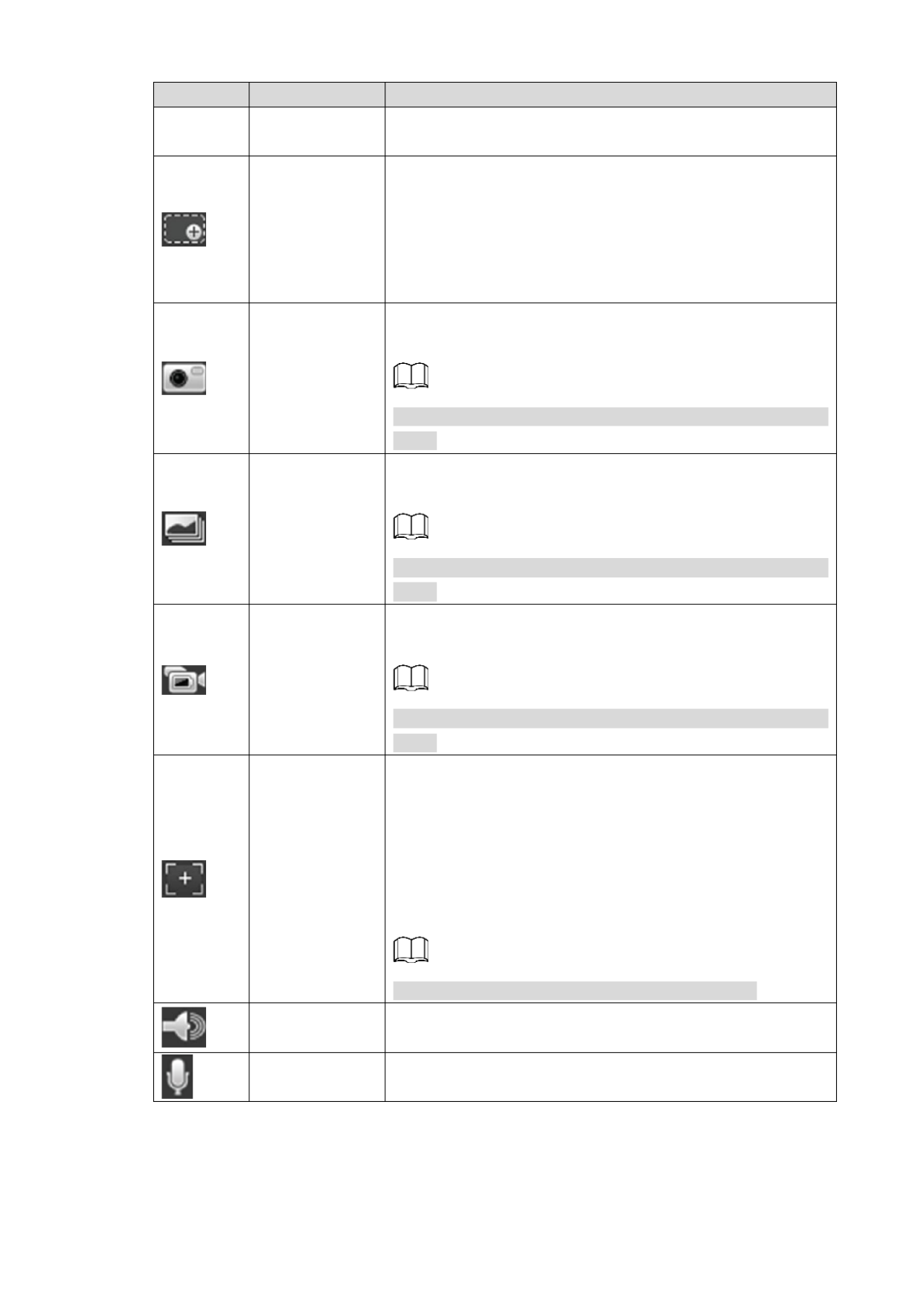
4.2.3 Live view Function B ar
For the live view function bar, please see Table 4-2.
Table 4-2 Description Live view function bar of
Icon
Function
Description
Manual position
Manually position the tracking speed dome to the selected
location of corresponding panoramic camera.
Click the icon and click or select randomly on the image of
panoramic camera channel, the tracking speed dome will
automatically position the selected location.
For multi-sensor panoramic network camera + PTZ
camera, before enabling manual position, make sure
that you have enabled alarm track and smart track
calibration. For details, see "5.2 Setting Smart Track ."
For panoramic network camera before enabling ,
manual position, make sure that you have enabled
panoramic linkage. For details, s "5.3 Setting ee
Panoramic Calibration ."
Regional Focus
Select channel image of the tracking speed dome, click the
icon and click or select randomly on the channel image of
the tracking speed dome, and then the speed dome can
realize auto focus upon the selected region.
Wiper
Controls the wiper of the camera.
Click the icon to enable or disable wiper function.
Ranging
Click the icon, select a point on the ground, and the distance
between the camera and the selected point will be
displayed.
Before using this function, you need to set the installation of
device first. For details, see "4.5.2.3.11 Configuring
Ranging ."
Gesture
Controls PTZ by operating the mouse on the live view of
tracking speed dome.
Select the live view tracking speed dome, click the iconof ,
press left-button and drag image to control PTZ. And you
can zoom the image through rolling mouse wheel.
Manual track
Click the icon, and select tracking target on the live view of
tracking speed dome, the camera tracks the selected target
automatically.
Relay- out
Displays alarm output state lick the icon to force enable or . C
force disable alarm output.
Alarm output state description:
Basic Configuration 13
Icon
Function
Description
Red: Alarm output enabled.
Grey: Alarm output disabled.
Digital Zoom
You can zoom video image through two operations:
Click the icon, and then select an area in the video
image to zoom in; right-click to resume. In zoom in
state, drag the image to check other area.
Click the icon, and then scroll the mouse wheel in the
video image to zoom in or out.
Snapshot
Click the icon to snap one picture of the current image, and it
will be saved to the defined storage path.
About viewing or configuring storage path, see "4.5.2.5
Path."
Triple Snapshot
Click the icon to snap three pictures of the current image,
and they will be saved to the defined storage path.
About viewing or configuring storage path, see "4.5.2.5
Path."
Record
Click the icon to record video, and it will be saved to the
defined storage path.
About viewing or configuring storage path, see "4.5.2.5
Path."
Easy Focus
Click the icon, the AF Peak AF Max (focus eigenvalue) and
(max focus eigenvalue) are displayed on the video image.
AF Peak: the eigenvalue of image definition, it displays
during focus.
AF Max: the best eigenvalue of image definition.
The closer the AF peak value and the AF max value are
with each other, the better the focus is.
Easy focus closes automatically after five minutes.
Audio
Click the icon to enable or disable audio output.
Talk
Click the icon to enable or disable intercom.

Basic Configuration 14
4.2.4 Window Adjustment B ar
4.2.4.1 Adjustment
This section introduces the adjustment of image. For details, see Table 4-3.
Table 4-3 Description adjustment bar of
Icon
Function
Description
Image Adjustment
Click the icon, and then the Image Adjustment
interface is displayed at the right side of the Live
interface. You can adjust brightness, contrast, hue,
and saturation.
The adjustment is only available on web interface, and
it does not adjust the device parameters.
rightness adjustment): Adjusts the overall (B
image brightness, and changes the value when
the image is too bright or too dark. The bright and
dark areas will have equal changes.
ontrast adjustment): Changes the value (C
when the image brightness is proper but contrast
is not enough
adjustment): Makes the color deeper or (Hue
lighter. The default value is made by the light
sensor, and it is recommended.
aturation adjustment): Adjusts the image (S
saturation, this value does not change image
brightness.
Original Size
Click the icon, and then the video displays with original
size.
Full Screen
Click the icon to enter full screen mode; double-click
or press Esc to exit.
W:H
Click the icon to resume to original ratio or change
ratio.
Fluency
Click the icon to select the fluency from Realtime,
Fluency . and Normal
Realtime: Guarantee the realtime of image.
When the bandwidth is not enough, the image
might not smooth. be
Fluency: Guarantee the fluency of image. There
might be delay between live view image and

Basic Configuration 15
Icon
Function
Description
real-time image.
Normal: It is between Realtime and Fluency.
Rule Info
Click the icon, and then select Enable to display smart
rules and detection box; select Disable to stop.
PTZ
Click the icon, and the control panel displayed PTZ is
on the right of the interface. You can control and Live
call PTZ function. For details, see "4.3.3 Calling PTZ ."
Zoom and Focus
Adjust focal length to zoom in and out video image.
Click the icon, and the Zoom and Focus configuration
interface is displayed the right side of the at Live
interface. You can control and call PTZ function. For
details, see "4.2.4.2 Zoom and Focus ."
Fisheye
Click the icon, and then the fisheye configuration
interface is displayed on the right of the Live interface.
For details, see "4.2.4.3 Fisheye ."
Face
Click the icon, and the face detection /recognition
results are displayed on Live interface.
For face recognition, see "5.9 Setting Face
Recognition ."
For face detection: see "5.10 Setting Face
Detection ."
ANPR
Click the icon, and the ANPR results are displayed on
Live interface. For details, see "5.14 Setting ANPR ."
Video
Structuralization
Click the icon, the video structuralization results are
displayed on interface. For details, see "5.15 Live
Setting Video Structralization ."
Window Layout
When view multi-channel image, you can select
display layout.
Crowd Map
Click the incon and select . The Enable Crowd Map
interface is dispalyed. For details, see "5.8 Setting
Crowd Map ."
4.2.4.2 Zoom and Focus
You can adjust focal length to zoom in and out video image; by adjusting focus manually,
automatically or within a certain area, you can change image clarity or correct adjusting errors.
The focus would adjust automatically after zooming in or out.

Basic Configuration 16
Zoom and focus Figure 4-5
Table 4-4 Description zoom and focus of
Parameter
Function
Zoom
Changes the focal length of the camera to zoom in or out the image.
1. Set the value. The Speed Speed is the adjustment range in one click.
The larger the value is, the more the image would zoom in or out in one
click.
2. Click or hold / button, or drag the slider to adjust zoom. + –
Focus
Adjusts the optical back focal length to make the image clearer.
1. Set the value. The Speed Speed is the adjustment range in one click.
The larger the value is, the more the image would zoom in or out in one
click.
2. Click or hold / button, or drag the slider to adjust zoom. + –
Auto Focus
Adjusts image clarity automatically.
Do not make any other operation during auto focus process.
Restore All
Restores focus to default value and corrects errors.
You can restore the focus if the image has poor clarity or has been zoomed
too frequently.
Regional
Focus
Focus on the subject of a selected area.
Click Regional Focus, and then select an area in the image, the camera
performs auto focus in that area.
Refresh
Get the latest zoom setting of the device.

Basic Configuration 17
4.2.4.3 Fisheye
You can configure the install mode, display mode and VR mode of fisheye devices as needed.
For details, see Table 4-5.
Install Mode: Install the fisheye camera according to the actual situation.
Display Mode: Select the display mode of live view.
VR Mode: Select VR mode to display the image in stereo mode.
eye Figure 4-6 Fish
Table 4-5 Description Fisheye configuration of
Parameter
Description
Installation M ode
Includes ceiling, wall, and ground.

Basic Configuration 18
Parameter
Description
Display Mode
You can configure how the image needs to be presented (all display
modes support original size image by default); there are different
display modes for each installation mode.
Ceiling: 1P+1, 2P, , , , , 1+2 1+3 1+4 1P+6 1+8.
Wall: 1P, , , 1P+3 1P+4 1P+8.
Ground: 1P+1, 2P, , , , 1+3 1+4 1P+6 1+8.
The image will be on original size by default when switching
installation mode.
Ceiling/Wall/Ground
Original
image
The original image before correction.
1P+1
360° rectangular panoramic image screen +
independent sub-screens.
You can zoom or drag the image in all the
screens.
You can rotate the image rectangular on
panoramic image screen to change the start
point.
2P
Two associated 180° rectangular image screens,
and at any time, the two screens form a 360°
panoramic image. It is also called Dual panoramic
image.
You can rotate the image on the two rectangular
panoramic image screens to change the start point,
and the two screens link each other.
Ceiling /Ground
1+2
Original image screen + two independent
sub-screens.
You can zoom or drag the image in all the
screens.
You can rotate the image the original image on
screen to change the start point.
1+3
Original image screen + three independent
sub-screens.
You can zoom or drag the image in all the
screens.
You can rotate the image the original image on
screen to change the start point.
1+4
Original image screen + four independent
sub-screens.
You can zoom or drag the image in all the
screens.
You can rotate the image the original image on
screen to change the start point.

Basic Configuration 19
Parameter
Description
1P+6
360° rectangular panoramic screen + six
independent sub-screens.
You can zoom or drag the image in all the
screens.
You can rotate the image rectangular on
panoramic image screen to change the start
point.
1P +8
Original image screen + eight independent
sub-screens.
You can zoom or drag the image in all the
screens.
You can rotate the image the original image on
screen to change the start point.
Wall mounted
1P
180° rectangular panoramic image screen (from left
to right ).
You can zoom or drag the image in all the
screens.
You can rotate the image the original image on
screen to change the start point.
1P+3
180° rectangular panoramic image screen + three
independent sub-screens.
You can zoom or drag the image in all the
screens.
You can rotate the image the rectangular on
panoramic image screen to change the start
point.
1P+4
180° rectangular panoramic image screen + four
independent sub-screens.
You can zoom or drag the image in all the
screens.
You can rotate the image the rectangular on
panoramic image screen to change the start
point.
1P+8
180° rectangular panoramic image screen + eight
independent sub-screens.
You can zoom or drag the image in all the
screens.
You can rotate the image the rectangular on
panoramic image screen to change the start
point.
VR Mode
Panorama
Drag or cross the screen 360° to unfold the
distortion panorama, and you can drag the image in
left/right direction.
Basic Configuration 20
Parameter
Description
Semi-circle
You can drag the image in upper/lower/left/right
direction. Press I to display the panorama, and
press O to return the orignal size.
Press S to rotate the image in anticlockwise
direction, and press E to stop the rotation.
Scroll the mouse wheel to zoom the image.
Cylinder
Display the distortion panorama in 360°circularity.
You can drag the image in upper/lower/left/right
direction. Press I to display the panorama, and
press O to return the orignal size.
Press S to rotate the image in anticlockwise
direction, and press E to stop the rotation.
Scroll the mouse wheel to zoom the image.
Asteroid
You can drag the image in upper/lower/left/right
direction. Press I to display the panorama, and
press O to return the orignal size.
Press the left mouse-button to slide down to
display the image on the planet surface.
Scroll the mouse wheel to zoom the image.
PTZ Operation 4.3
This chapter introduces PTZ parameter configuration, PTZ control and PTZ function
configuration.
4.3.1 Configuring External PTZ Protoc ol
Precondition
Access external PTZ through RS-485
You have configured the parameters of serial port. For details, see "4.8.6.1 Serial Port
Settings ."
Procedures
Select Setting > PTZ Setting > Protocol. Step 1
The PTZ Setting interface is displayed. See Figure 4-7.

Basic Configuration 21
PTZ Setting Figure 4-7
Select the PTZ protocol Step 2
Click . OKStep 3
4.3.2 Configuring PTZ Function
4.3.2.1 Preset
Preset means certain defined positions that the camera can make quick orientation to. It
contains several defined parameters, including PTZ pan and tilt angles, camera focus, and
location.
Select Setting > PTZ settings > Function > Preset. Step 1
The interface is displayed. See Figure 4-8. Preset
Preset Figure 4-8
Set the speed, and click direction buttons, to adjust the parameters of and Step 2
direction, zoom, focus and iris, to move the camera to the position you need.
Click Add to the current position to be preset, and the preset is displayed in Step 3 add a
preset list.
Double-click the preset title to edit the title. Step 4
Click to save the preset. Step 5
Basic Configuration 22
Other Operation
Click to delete the preset.
Click Remove All to remove all presets.
4.3.2.2 Tour
Tour means a series of movements that the camera makes along several preset points.
Precondition
You have set several presets.
Procedures
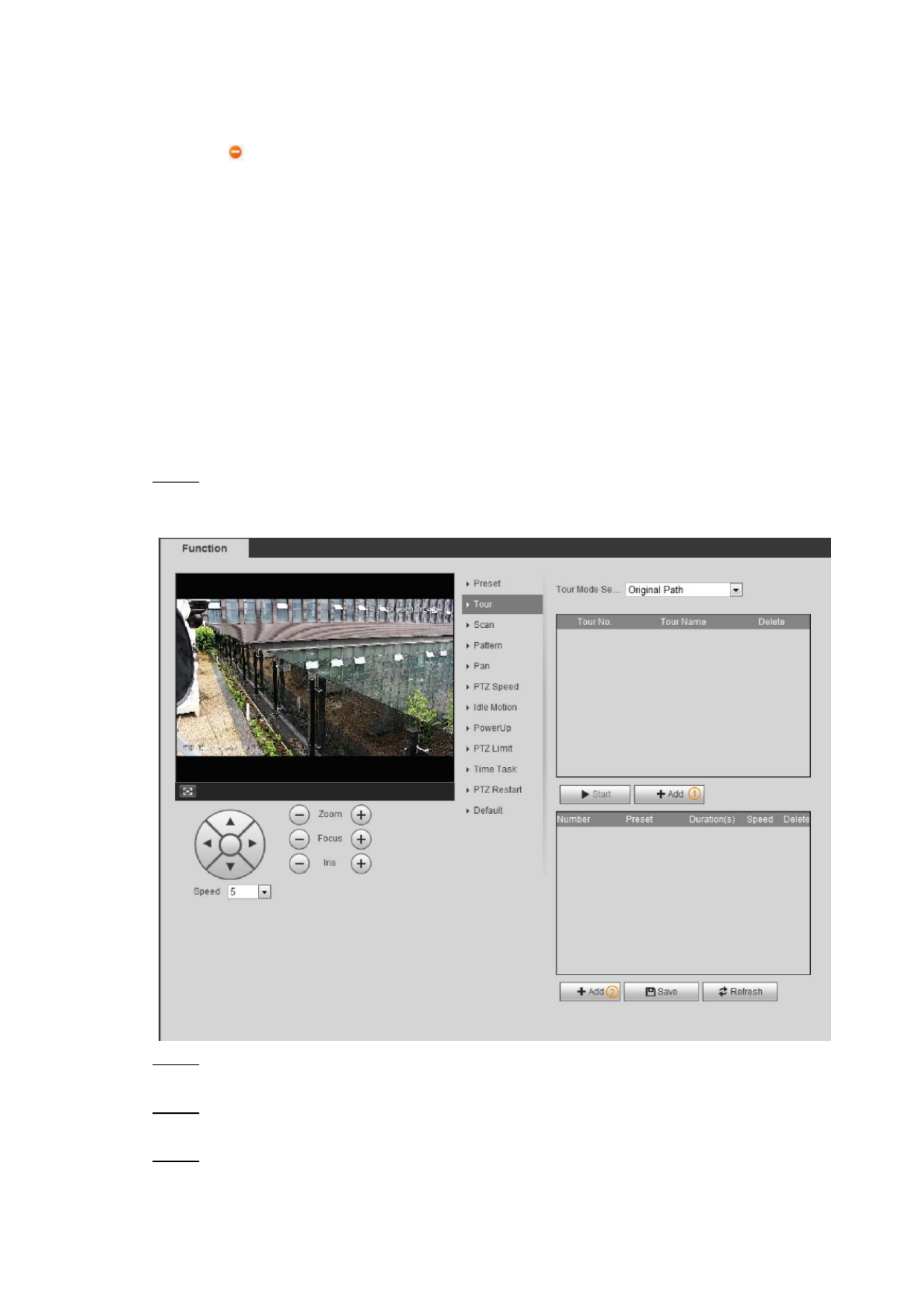
Select Setting > PTZ settings > Function > Tour. Step 1
The Tour interface is displayed. S Figure 4-9. ee
Tour Figure 4-9
Click Add ① to add tour. Step 2
Double-click the tour name to edit the name.
Click Add ② to add preset. Step 3
Double-click the duration to set the duration.
Select the tour mode. Step 4
Original Path: The PTZ camera moves the older of the selected presets. in

Basic Configuration 23
Shortest Path: The PTZ camera ranks presets by distance, and moves in the
optimal path.
Click to complete the configuration. Step 5 Save
Click to start touring. Step 6 Start
If you operate PTZ during tour, the camera will stop tour.
Click to stop touring. Stop
4.3.2.3 Scan
Scan means the camera moves horizontally on a certain speed between the defined left and
right boundaries.
Select Setting > PTZ settings > Function > Scan. Step 1
The interface is displayed. See Figure 4- . Scan 10
Scan Figure 4-10
Select the scan number, and set the speed. Step 2
Click to set left limit and left limit. Step 3 Setup
1) Click Set Left Limit to set the current position to be the left limit.
2) Click Set Right Limit to set the current position to be the right limit.
Click to start scanning. Step 4 Start
Click to stop scanning. Stop
4.3.2.4 Pattern
Pattern means a record of a series of operations that you make to the camera, and when
pattern starts, the camera performs the operations repeatedly. The record includes the manual
operations that the user performed to the PTZ, and the changes in focus and zoom.
Select Setting > PTZ settings > Function > Pattern. Step 1

Basic Configuration 24
The interface is displayed. See Figure 4- . Pattern 11
Pattern Figure 4-11
Select the pattern number. Step 2
Click , and then click . Adjust the parameters of direction, zoom, focus Step 3 Setup Start Rec
and iris according to the actual situation.
Click Stop Rec to stop recording. Step 4
Click to start patterning. Step 5 Start
Click Stop to start patterning.
4.3.2.5 Pan
Enable Pan, the camera can realize 360°horizontal rotation.
Select Setting > PTZ settings > Function > Pan. Step 1
The interface is displayed. See Figure 4- . Pan 12

Basic Configuration 25
Pan Figure 4-12
Set the pan speed and click , and the camera starts horizontal rotation. Step 2 Start
Click to stop rotation. Stop
4.3.2.6 PTZ Speed
Select Setting > PTZ settings > Function > PTZ Speed. Step 1
The PTZ Speed interface is displayed. See Figure 4- . 13
PTZ speed Figure 4-13
Select the PTZ speed. Step 2

Basic Configuration 26
4.3.2.7 Idle Motion
PTZ idle motion is a function of a PTZ camera where you can set an interval of idle time before
the camera defaults to one of the following: Preset, scan, tour, or pattern.
Precondition
You have configured the PTZ motions, including preset, scan, tour, or pattern.
Procedures
Select Setting > PTZ settings > Function > Idle Motion. Step 1
The Idle Motion interface is displayed. See Figure 4- . 14
Idle motion Figure 4-14
Select Enable check box to enable idle motion. Step 2
Select idle motion and set idle time. Step 3
You need to select the corresponding number for some selected idle motions, such as
Preset001.
Click Save Step 4
4.3.2.8 PowerUp
After setting Powerup motion, the camera will execute the configured motion after power up.
Precondition
You have configured the PTZ motions, including preset, scan, tour, or pattern.

Basic Configuration 27
Procedures
Select Setting > PTZ settings > Function > PowerUp. Step 1
The PowerUp interface is displayed. See Figure 4-15.
PowerUp Figure 4-15
Select Enable check box to enable powerup motion. Step 2
Select the powerup motion. Step 3
When you select , the system will execute the last motion before power off for 20 Auto
s.
Click . OKStep 4
4.3.2.9 PTZ Limit
After setting PTZ limit, the camera can only move in the set area.
Select Setting > PTZ settings > Function > PTZ Limit. Step 1
The PTZ Limit interface is displayed. See Figure 4-16.

Basic Configuration 28
PTZ limit Figure 4-16
Control camera direction, click to set up line. Step 2 Setting ①
Control camera direction, click to set down line. Step 3 Setting ②
Click Live to live view the set up/down line.
Select Enable check box to enable PTZ limit function. Step 4
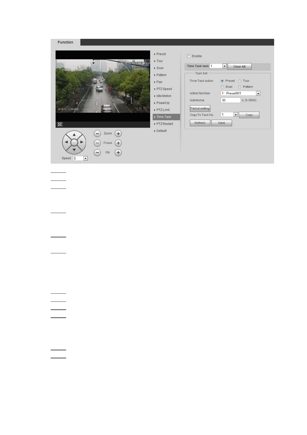
4.3.2.10 Time Task
After setting time task, the camera executes the motions during the set period.
Precondition
You have configured the PTZ motions, including preset, scan, tour, or pattern.
Procedures
Select Setting > PTZ settings > Function > Time Task. Step 1
The Time Task interface is displayed. See Figure 4- . 17
Basic Configuration 29
Time task Figure 4-17
Select Enable check box to enable time task function. Step 2
Select the time task number. Step 3
Select the time task action. Step 4
You need to select the corresponding action number for some selected time task
actions.
Set the auto home time in AutoHome. Step 5
AutoHome: When you call PTZ, the time task will be interrupted. After setting
AutoHome time, the camera will resume the time task automatically.
Click Period setting to set the time of the task, then click . Step 6 and Save
For setting arm/disarm time, See "5.1.1.1 Setting Period ."
ick Cl Save. Step 7
Other Operations
You can copy the configurations of existing task number to other task number.
Select the existing task number in Time Task num. Step 1
Select the task number to be configured in Copy To Task No. Step 2
Click Copy. Step 3
Click . Step 4 Save
4.3.2.11 PTZ Restart
Select Setting > PTZ settings > Function > PTZ Restart. Step 1
The PTZ Restart interface is displayed. See Figure 4- . Step 2 18

Basic Configuration 30
PTZ restart Figure 4-18
Click PTZ Restart to restart PTZ. Step 3
4.3.2.12 Default
This function restores the device to default configuration.
Select Setting > PTZ settings > Function > Default. Step 1
The Default interface is displayed. See Figure 4- . Step 2 19

Basic Configuration 31
Default Figure 4-19
Step 2 Click and the PTZ function is restored to default. Default
4.3.3 Calling PTZ
Click interface, the PTZ configuration panel is displayed. You can control on Live and
PTZ and call PTZ function.
4.3.3.1 PTZ Control
You can rotate device, zoom image, and adjust iris through PTZ control or virtual joystick. See
Figure 4- and Figure 4- . 20 21

Basic Configuration 32
PTZ control Figure 4-20
Joystick Figure 4-21
: Rotate PTZ direction through direction button. PTZ supports eight directions:
left/right/up/down/upper left/upper right/bottom left/bottom right. Click , and draw a box
in the image, PTZ will rotate, focus and quickly position the defined scene.
: Rotate PTZ direction through joystick. Press , and drag it to the direction
that you need, then PTZ will move to the defined direction.
Speed: Measure the rotation speed. The bigger the step length is, the faster the speed
becomes.

Basic Configuration 33
Zoom, focus and iris: Click or to adjust zoom, focus and iris.
4.3.3.2 PTZ Function
Select the PTZ function from the dropdown list to call the corresponding functions, including
Scan, Preset, Tour, Pattern, Pan, Go to, Assistant and Light Wiper. See Figure 4- . For details, 22
see Table 4-6. Before calling PTZ function, see "4.3.2 Configuring PTZ Function" to configure
PZT function.
If an external PTZ is connected to the camera, the configurations are valid only when the
corresponding functions are available on the external PTZ.
The range of PTZ function (preset, tour and so on) depends on the PTZ protocol.
PTZ function Figure 4-22
Table 4-6 PTZ Description function of
Parameter
Description
Scan
Set scan number click the camera moves horizontally on a certain and Start,
speed between the set left and right limit. Click Stop to stop scanning.
Preset
Set preset number and click the camera quick positions the Go to, ly
corresponding preset.
Tour
Set tour number and click the camera moves the older of the s Start, in et
presets. Click to stop touring. Stop
Pattern
Set pattern number and click , the camera moves continuously Start
according to the operation records. Click to stop patterning. Stop
Operation records include the information of manual operation, focus and
zoom.
Pan
Click and the camera rotates 360 at a certain speed in horizontal Start, °
direction.
Go to
Set horizontal angle, vertical angle, and zoom. Click position Go to to a
certain point accurately.
Assistant
Set assistant number and click Aux On to enable the corresponding
assistant function, and then you can adjust the camera. Click to Aux On
disable the corresponding assistant function
Light/Wiper
Set the light or wiper of the camera.
Click to enable light/wiper function. Enable
Click to disable light/wiper function. Disable

Basic Configuration 34
Playback 4.4
This section introduces playback related functions and operations, including video playback
and picture playback.
Before playing back video, you need to configure record time range, record storage
method, record schedule and record control. For details, see "5.1.1.2.1 Setting Record
Plan ."
Before playing back picture, you need to configure snapsh time range, snapshot storage ot
method, snapshot plan. For details, see "5.1.1.3.1 Setting Snapshot Plan ."
When using Dahua smart card, make sure the card has been authenticated before using.
4.4.1 Playback Interface
Click Playback tab, and the Playback interface is displayed. S Figure 4- ee 23 and Figure 4- . 24
For details, see Table 4-7.
Video Playback Figure 4-23

Basic Configuration 35
Picture Playback Figure 4-24
Table 4-7 Playback interface description
No
Function
Description
1
Fisheye
Click you can select display mode according to the ,
installation mode during playback.
This function is only available on fisheye cameras.
Rules Info
Click , intelligent rules and object detection box are
displayed. It is enabled by default.
Rules Info is valid only when you enabled the rule during
recording.
2
Sound
Controls the sound during playback:
: Mute mode.
: Vocal state, and you can adjust the sound.

Basic Configuration 36
No
Function
Description
3
Play control bar
Controls playback:
: Click the icon to play back record.
: Click the icon to stop playing back record.
: Click the icon to play the next frame.
When you enable the function of playing video by frame,
stop playback.
: Click the icon to slow down the play.
: Click the icon to speed up the play.
4
Progress bar
Displays the record type and the corresponding period.
Click any point in the colored area, and the system will play
back the record from the selected moment.
Each record type has its own color, and you can see their
relations in Record Type bar.
5
Record/Snapshot
Type
Select the record type or snapshot type:
Record type includes General Event Alarm Manual, , ,
Snapshot type includes General Event Alarm, ,
6
Assistant
: You can zoom video image of the selected area
through two operations:
Click the icon, and then select an area in the video
image to zoom in; right-click to resume. In zoom in
state, drag the image to check other area.
Click the icon, and then scroll the mouse wheel in the
video image to zoom in or out.
: Click the icon to snap one picture of the current
image, and it will be saved to the defined storage path.
About viewing or configuring storage path, see "4.5.2.5
Path."
7
Playback video
You can select the file type, data source, and record date.
8
Video clip
Clip a certain record and save it. For details, see "4.4.3 Clipping
Video ."

Basic Configuration 37
No
Function
Description
9
Time format of
progress bar
Includes 4 time formats: , , ,
. Take as an example, the whole
progress stands for 24 hours.
4.4.2 Playing back Video or Picture
This section introduces the operation of video playback and picture playback. This section
takes video playback as an example.
Select from dav Record Type SD card Data Src drop-down list and in the drop-down Step 1
list S Figure 4- . . ee 25
Select jpg from Record Type drop-down list when playing back picture, and you do not
need to select data source.
File type selection Figure 4-25
Select the record type in Record Type. See Figure 4- . Step 2 26
Record type selection Figure 4-26
When selecting the record type, you can select the specific event types from the Event as
playback file list, such as Motion Detection Video Tamper, and . See Scene Changing
Specific event types.

Basic Configuration 38
Specific event types Figure 4-27
Select the month and year of the video you want to play. Step 3
Those dates with blue color indicate there were videos recorded in those days.
Play video Step 4
Click in the control bar.
The system plays the recorded video of the selected date (in the order of time).
Click any point in the colored area on the progress bar, see Figure 4- . 28
The playback starts from that moment.
Progress bar Figure 4-28
Click , the video files of the selected date would be listed. S Figure 4-ee 29.
Enter the start time and end time, and then click to search all files between the
start time and end time. Double-click the file in the list, and the system plays the
video and displays file size, starting time, and ending time.

Basic Configuration 39
Playback file list (1) Figure 4-29
4.4.3 Clipping Video
Click , the video files of the selected date are listed. Step 1
Select or dav mp4 in Download Format. Step 2
Click on the progress bar to select the start time of the target video, and then clickStep 3
. See Figure 4-30.
Clipping Video Figure 4-30
Click again on the progress bar to select the end time of the target video, and then clickStep 4
.
Click to download the video. Step 5
The system will prompt that it can playback and download at the same time. not
Click . Step 6 OK
The playback stops and the clipped file is saved in the defined storage path. For the
configuration of storage path, see "4.5.2.5 Path."

Basic Configuration 40
4.4.4 Downloading Video or Picture
Download video or picture to a defined path. You can download single video or picture file, or
download them in batches. This section takes downloading video as an example.
Playback and downloading at the same time is not supported.
Operation might be vary with different owsers and the actual product shall prevail br ,
For details of viewing or setting storage path, see "4.5.2.5 Path."
4.4.4.1 Downloading Single File
Select from dav Record Type SD card Data Src drop-down list and in the drop-down Step 1
list .
Select jpg from Record Type drop-down list when playing back picture, and you do not
need to select data source.
Click , the video files of the selected date are listed. S Figure 4- . Step 2 ee 29
Select or dav mp4 in Download Format. Click behind the file to de download. Step 3
The system starts to download the file to the defined path. When downloading picture,
you do not need to select t download format. he
4.4.4.2 Downloading File in Batches
Click on the playback interface. Step 1
The Batch Download interface is displayed. See Figure 4-31.
Batch download Figure 4-31
Select the record type, set the start time and end time then click . Step 2 , and Search

Basic Configuration 41
T searched files are listed he
Select the files to be downloaded, select or from drop-down list and Step 3 dav mp4 Format ,
then set the storage path. Click Download.
The system starts to download the file to the defined path. When downloading picture,
you do not need to select the download format.
Camera 4.5
This section introduces the camera setting, including conditions, video and audio.
Camera parameters of different devices might vary, and the actual product shall prevail.
4.5.1 Conditions
Configure camera parameters of the camera to ensure surveillance goes properly.
4.5.1.1 Conditions
Configure camera parameters according to the actual situation, including picture, exposure,
backlight and white balance.
4.5.1.1.1 Interface Layout
Configure camera parameters to improve the scene clarity, and ensure surveillance goes
properly. See Figure 4- . 32
You can select from normal, day and night mode to view the configuration and the effect of
the selected mode including picture, exposure, backlight so on. , and and
Camera with PZT function supports zoom, focus and iris operations. See Figure 4-33.
Configure speed, click direction button, to adjust the direction, zoom, fand ocus
and iris and so on, to adjust the camera to the proper position.

Basic Configuration 42
Camera conditions Figure 4-32
Camera conditions PTZ Camera ) Figure 4- ( 33
4.5.1.1.2 Picture
You can configure picture parameters according to the actual needs.
Select Setting > Camera > Conditions > Conditions > Picture. Step 1
The interface is displayed. See Figure 4- . Picture 34

Basic Configuration 43
Picture Figure 4-34
Configure picture parameters. For details, see Table 4-8. Step 2
Table 4-8 Description picture parameter of
Parameter
Description
Style
Select picture style from soft, standard and vivid.
Soft Default image style, displays the actual color of the image. :
Standard The hue of the image is weaker than the actual one, and :
contrast is smaller.
Vivid The image is more vivid than the actual one. :
Brightness
Changes the value to adjust the picture brightness. The bigger the value is, the
brighter the picture will be, and the smaller the darker. The picture might be
hazy if the value is configured too big.
Contrast
Changes the contrast of the picture. The bigger the value is, the more the
contrast will be between bright and dark areas, and the smaller the less. If the
value is set too big, the dark area would be too dark and bright area easier to
get overexposed. The picture might be hazy if the value is set too small.
Saturation
Makes the color deeper or lighter. The bigger the value is, the deeper the color
will be, and the lower the lighter. Saturation value doesn’t change image
brightness.
Sharpness
Changes the sharpness of picture edges. The bigger the value is, the clearer
the picture edges will be, and if the value is set too big, picture noises are more
likely to appear.
Gamma
Changes the picture brightness and improves the picture dynamic range in a
non-linear way. The bigger the value is, the brighter the picture will be, and the
smaller the darker.
Mirror
Select , and the picture would display with left and right side reversed. On

Basic Configuration 44
Parameter
Description
Flip
Changes the display direction of the picture, see the options below.
0°: Normal display.
90°: The picture rotates 90° clockwise.
180°: The picture rotates 90° counterclockwise.
270°: The picture flips upside down.
For some models, please set the resolution to 1080p or lower when using 90°
and 180°. For details, see "4.5.2.1 Video ."
EIS
Corrects the device shaking with difference comparison algorithm and
improves the image clarity, effectively solves the picture shaking problem.
Picture
Freeze
When you call a preset, the image displays the preset location, not the rotation
image.
Click . Step 3 Save
4.5.1.1.3 Exposure
Configure iris and shutter to improve image clarity.
Cameras with true WDR don't support long exposure when WDR is enabled in . Backlight
Select Setting > Camera > Conditions > Conditions > Exposure. Step 1
The Exposure interface is displayed. S Figure 4- . ee 35
Exposure Figure 4-35
Configure exposure parameters. For details, see Table 4-9. Step 2

Basic Configuration 45
Table 4-9 Description exposure parameter of
Parameter
Description
Anti-flicker
You can select from 50Hz, 60Hz and Outdoor.
50Hz: when the current is 50Hz, the system adjusts the exposure
according to ambient light automatically to ensure there is no stripe
appears.
60Hz: when the current is 60Hz, the system adjusts the exposure
according to ambient light automatically to ensure there is no stripe
appears.
Outdoor: You can select any exposure mode as needed.
Mode
Device exposure modes, the options are:
Auto: adjusts the image brightness according to the actual condition
automatically
Gain Priority: When the exposure range is normal, the system
prefers the configured gain range when auto adjusting according to
the ambient lighting condition. If the image brightness is not enough
and the gain has reached upper or lower limit, the system adjusts
shutter value automatically to ensure the image at ideal brightness.
You can configure gain range to adjust gain level when using gain
priority mode.
Shutter priority: When the exposure range is normal, the system
prefers the configured shutter range when auto adjusting according
to the ambient lighting condition. If the image brightness is not
enough and the shutter value has reached upper or lower limit, the
system adjusts gain value automatically to ensure the image at ideal
brightness.
Iris priority: The iris value is set to a fixed value, and the device
adjusts shutter value then. If the image brightness is not enough and
the shutter value has reached upper or lower limit, the system
adjusts gain value automatically to ensure the image at ideal
brightness.
Manual: Configure gain and shutter value manually to adjust image
brightness.
When the Anti-flicker is set to Outdoor, you can select Gain priority or
Shutter priority in the list. Mode
Exposure Comp
Sets the value, and it ranges from 0 to 50. The bigger the value is, the
brighter the image is.
Shutter
Set the effective exposure time. The value is smaller, the shorter the
exposure time is.
Shutter range
When selecting or in setting Shutter Priority Manual Mode, and
Customized Range Shutter in , you can set shutter range, and the unit
is ms.

Basic Configuration 46
Parameter
Description
Gain
When selecting Gain Priority Manual Mode or in , you can set shutter
range. With Min. illumination, the camera increase Gain automatically to
get clearer images.
Iris
When selecting Aperture Priority in , you can set iris range. Mode
Auto Iris
This configuration is available only when the camera is equipped with
auto-iris lens.
When auto iris is enabled, the iris size changes automatically
according to the ambient lighting condition, and the image
brightness changes accordingly.
When auto iris is disabled, the iris stays at full size and doesn’t
change no matter how much ambient lighting condition changes.
2D NR
Average single-frame dots and other dots around to reduce noise.
3D NR
Works with multi-frame (no less than 2 frames) images and reduces
noise by using the frame information between previous and latter frames.
Grade
This configuration is available only when the 3D NR is enabled.
The higher the NR level is, the better the result will be.
Click . Step 3 Save
4.5.1.1.4 Backlight
You can select backlight mode from Auto, BLC, WDR HLS. , and
Auto: Adjusts the brightness according to the environment.
When in BLC mode, the camera gets clearer image of the dark areas on the target when
shooting against light.
When in WDR mode, the camera constrains over bright areas and compensates dark
areas to improve the image clarity.
When in HLS mode, the camera dims strong light, and it is applicable to the entrance of toll
station or parking lot. Works well for taking pictures of human face or car plate detail under
extreme low ambient light.
Select Setting > Camera > Conditions > Conditions > Backlight. Step 1
The Backlight interface is displayed. S Figure 4- . ee 36
Backlight Figure 4-36
Configure backlight parameters. For details, see Table 4- . Step 2 10

Basic Configuration 47
Table 4- Description backlight mode 10 of
Backlight mode
Description
Auto
The system adjusts image brightness according to ambient lighting
condition automatically to ensure image clarity.
BLC
You can select Default mode or Customized mode.
When in mode, the system adjusts exposure according to Default
ambient lighting condition automatically to ensure the clarity of the
darkest area.
When in mode, the system auto adjusts exposure Customized
only to the set area according to ambient lighting condition to
ensure the image of the set area at ideal brightness.
WDR
The system dims bright areas and compensates dark areas to ensure
the clarity of all the area.
There might be a few seconds of video loss when the device is
switching to WDR mode from other mode.
HLS
The system constrains bright areas and reduces halo size to dim the
overall brightness.
Click to finish configuration. SaveStep 3
4.5.1.1.5 WB
WB function makes the image color display precisely as it is. When in WB mode, white objects
would always display white color in different environments.
Select Setting > Camera > Conditions > Conditions > WB. Step 1
The interface is displayed. S Figure 4- . WB ee 37
WB Figure 4-37
Configure WB mode. For details, see Table 4- . Step 2 11
Table 4- Description WB mode 11 of
WB mode
Description
Auto
The system compensates WB according to color temperature to ensure
color precision.
Natural
The system auto compensates WB to environments without artificial light to
ensure color precision.
Street Lamp
The system compensates WB to outdoor night scene to ensure color
precision.

Basic Configuration 48
WB mode
Description
Outdoor
The system auto compensates WB to most outdoor environments with
natural or artificial light to ensure color precision.
Manual
Configure red and blue gain manually; the system auto compensates WB
according to color temperature.
Regional
Custom
The system compensates WB only to the set area according to color
temperature to ensure color precision.
Click . Step 3 Save
4.5.1.1.6 Day & Night
Configure the display mode of the image. The system switches between color and
black-and-white mode according to the actual condition.
Select Setting > Camera > Conditions > Conditions > Day & Night. Step 1
The Day & Night interface is displayed. S Figure 4- . ee 38
Day & Night Figure 4-38
Configure day & night parameters. For details, see Table 4- . Step 2 12
Table 4- Description day & night mode 12 of
Parameter
Description
Mode
You can select device display mode from color or black- -white mode, and and
the options are:
Day & Night configuration is independent from profile management
configuration.
Color: The system displays color image.
Auto: The system switches between color and black-and-white display
according to the actual condition.
B/W: The system displays black- -white image. and
Sensitivity
This configuration is available only when the Day & Night set as Mode Auto.
You can configure camera sensitivity in switching between color and
black-and-white mode.
Delay
This configuration is available only when the Day & Night set as Mode Auto.
You can configure the delay when camera switching between color and
black-and-white mode. The lower the value is, the faster the camera switches
between color and black-and-white mode.

Basic Configuration 49
Click . SaveStep 3
4.5.1.1.7 Zoom and Focus
Initialize lens to adjust zoom and focus. Only PZT camera supports lens initialization.
Select Setting > Camera > Conditions > Conditions > ZoomFocus. Step 1
The ZoomFocus interface is displayed. See Figure 4- . 39
Zoom and focus Figure 4-39
Configure zoom and focus parameters. For details, see Table 4- . Step 2 12
Table 4- Description zoom and focus 13 of
Parameter
Description
Digital Zoom
Select to enable digital zoom function. On
After the optical zoom reached the upper limit, enable digital zoom function,
you still can do digital zoom operation.
Zoom Speed
Adjusts zoom speed. The bigger the value is, the higher the speed is.
Mode
Sets focus model:
Auto: When image moves or object changes in the scene, the camera
will focus automatically.
Semi Auto : Click or corresponding to , t Focus or Zoom he
camera will focus. Calling preset, positioning accurately or rotating PTZ
also will trigger focus.
Manual: Focus Click or corresponding to to adjust the focus.
Focus Limit
When the focus length is too short, the camera will f on the dome cover. ocus
Sets the shortest focus distance to avoid focusing on the dome cover. You
can also change the focus speed by changing focus length.
Sensitivity
The sensitivity of triggering focus. The bigger the value is, the easier the
focus is triggered.
Click . Step 3 Save
4.5.1.1.8 IR Light
This configuration is available only when the device is equipped with IR light.
Select Setting > Camera > Conditions > Conditions > IR Light. Step 1
The interface is displayed. See Figure 4- . IR Light 40

Basic Configuration 50
IR light Figure 4-40
Configure IR light mode. For details, see Table 4- . Step 2 14
Table 4- Description IR light mode 14 of
IR light mode
Description
Manual
Adjust the brightness of IR light manually, and then the system will supply
IR light to the image accordingly.
Smart IR
The system adjusts the IR light intensity according to the ambient lighting
condition.
ZoomPrio
The system adjusts the IR light intensity automatically according to the
change of the ambient light.
When the ambient light turns darker, the system turns on the low
beam lights first, if the brightness is still not enough, it turns on the
high beam lights then.
When the ambient light turns brighter, the system dims high beam
lights until they are off, and then the low beam lights.
When the focus reaches certain wide angle, the system doesn't turn
on high beam light in order to avoid over-exposure in short distance.
In the meantime, you can configure light compensation manually to
make fine adjustment to the IR light intensity.
Off
IR light is off.
Click . Step 3 Save
4.5.1.1.9 Defog
The image quality compromised in foggy or hazy environment, and defog can be used then is
to improve image clarity.
Select Setting > Camera > Conditions > Conditions > Defog. Step 1
The interface is displayed. See Figure 4- . Defog 41

Basic Configuration 51
Defog Figure 4-41
Configure defog mode. For details, see Table 4- . Step 2 15
Table 4- Description defog mode 15 of
Defog
Descripti on
Manual
Configure function intensity and atmospheric light mode manually, and then the
system adjusts image clarity accordingly. Atmospheric light mode can be
adjusted automatically or manually.
Auto
The system adjusts image clarity according to the actual condition.
Off
Defog function is disabled.
Click . SaveStep 3
4.5.1.1.10 Fisheye
Select install mode and record mode according to the actual installation scene. When you the
camera outputting corrective stream accesses to the platform, the platform displays the
corrective image.
This function is only available on fisheye device.
Select Setting > Camera > Conditions > Conditions > Fisheye. Step 1
The Fisheye interface is displayed. S Figure 4- . ee 42
Fisheye Figure 4-42
Set install mode and record mode. For details, see Table 4- . Step 2 16

Basic Configuration 52
Table 4- Description fisheye mode 16 of
Parameter
Description
Install Mode
You can select Ceiling Wall Ground, , or .
Record Mode
1O: The original image before correction.
1P: 360°rectangular panoramic image.
2P: When the install mode is or , you can set this mode. Ceiling Ground
Two associated 180° rectangular image screens, and at any time, the
two screens form a 360° panoramic image.
1R: Original image screen + independent sub-screen. You can zoom or
drag the image in all the screens.
2R: Original image screen + two independent sub-screens You can .
zoom or drag the image in all the screens.
4R: . Original image screen + four independent sub-screens You can
zoom or drag the image in all the screens.
1O + Original image screen + three independent sub-screens Y3R: . ou
can zoom or drag the image in all the screens.
Click . Step 3 Save
4.5.1.2 Profile Management
The surveillance system works in different ways as profile configured in different time.
Select Setting > Camera > Conditions > Profile Management. Step 1
The Profile Management interface is displayed.
Manage profile. Step 2
When Profile Management General is set as , the surveillance system works
under configuration. General
General Figure 4-43
When is set as , you can select or in Profile Management Full Time Day Night
the Always Enable Always Enable list the surveillance system works under ,
configuration.
Full time Figure 4-44

Basic Configuration 53
When Profile Management Schedule is set as , you can drag the slide block to
set certain time as or . For example, set 8:00 18:00 as day, and 0:00Day Night – –
8:00 and 18:00 24:00 as night. –
Schedule Figure 4-45
When Profile Management Day & Night is set as , the surveillance system works
under Day & Night configuration.
Day/Night Figure 4-46
Click . Step 3 Save
4.5.1.3 Zoom and Focus
You can adjust image clarity through auto or manual focus; and adjust the image size through
zoom. For details, see 4.2.4.2 Zoom and Focus."
4.5.2 Setting Video Parameters
This section introduces video parameters, such as video, snapshot, overlay, ROI (region of
interest), and path.
Click Default, and the device is restored to default configuration. Click Refresh to view the
latest configuration.
4.5.2.1 Video
Configure video stream parameters, such as stream type, encode mode, resolution, frame rate,
bit rate type, bit rate, I frame interval, SVC, and watermark.
Select Setting > Camera > Video > Video. Step 1
The Video interface is displayed. S Figure 4-ee 47.

Basic Configuration 54
Video Figure 4-47
Configure video parameters. For details, see Table 4- . Step 2 17
Table 4- Description video parameter 17 of
Parameter
Description
Enable
Select the Enable check box to enable sub stream, it is enabled by default.
You can enable multiple sub streams simultaneously.
Enable
Select the Enable check box to enable sub stream, it is enabled by default.
You can enable both Sub Stream 1 and Sub Stream 2.
Enable
Encode
M ode
You can select encode mode from:
H.264: Main Profile Encode Mode.
H.264H: High Profile Encode Mode.
H.264B: Baseline Profile Encode Mode.
H.265: Main Profile Encode Mode.
MJPEG: When under this mode, the image requires high bit rate value to
ensure clarity, it is recommended to set the value to the biggest Bit Rate
value in the Reference Bit Rate.
Smart
Codec
Enable smart codec to improve video compressibility and save storage
space.
After smart codec is enabled, the device would stop supporting the third bit
stream, ROI, and smart event detection, and the actual interface shall prevail.
Resolution
The resolution of the video. The max resolution of different devices might
vary, and the actual product shall prevail.

Basic Configuration 55
Parameter
Description
Video Clip
This function is available only for sub stream 2 of select device.
1. Select Video Clip, and click .
The Area interface is displayed.
2. Select resolution as needed and clip image on the interface.
3. View the clipped video in Live interface (the live interface of sub stream 2
only displays the clipped area).
Frame Rate
(FPS)
The number of frame in one second of video. The bigger the FPS is, the
clearer and smoother the video will be.
Bit Rate
Type
You can select bit rate type from:
CBR: the bit rate changes little and keeps close to the defined bit rate
value.
VBR: the bit rate changes as monitoring scene changes.
The Bit Rate Type CBR can be only be set as when is set as Encode Mode
MJPEG.
Quality
This parameter can be configured only when the Bit Rate Type is set as
VBR.
There are six levels of Image quality, and the sixth is the best.
Reference
Bit Rate
The most suitable bit rate value range recommended to user according to the
defined resolution and frame rate.
Max Bit Rate
This parameter can be configured only when the Bit Rate Type is set as
VBR.
You can select the value of the Max Bit Rate according to the Reference Bit
Rate value.The bit rate then changes as monitoring scene changes, but the
max bit rate keeps close to the defined value.
Bit Rate
This parameter can be configured only when the Bit Rate Type is set as
CBR.
Select bit rate value in the list according to actual condition.
I Frame
Interval
The number of P frames between two I frames, and the I Frame Interval
range changes as changes. FPS
It is recommended to set I Frame Interval twice as big as FPS.
SVC
Scaled video coding, able to encode a high quality video bit stream that
contains one or more subset bit streams. When sending stream, to improve
inflency, the system will quit some data of related lays acoording to the
network staus.
1: The default value, which means no layered coding.
2, 3 and 4: The lay number that the video stream is packed.
Watermark
Settings
You can verify the watermark to check if the video has been tampered.
1. Select the check box to enable watermark function.
2. The default character is DigitalCCTV.
Watermark
Character
Click . Step 3 Save

Basic Configuration 56
4.5.2.2 Snapshot
You can configure snapshot parameters, including snapshot type, image size, quality and
interval.
Select Setting > Camera > Video > Snapshot. Step 1
The Snapshot interface is displayed, see Figure 4- . 48
Snapshot Figure 4-48
Configure snapshot parameters For details, see Table 4-. 18. Step 2
Table 4- Description snapshot parameter 18 of
Parameter
Description
Snapshot
Type
You can select General and . Event
General: The system takes snapshot as scheduled For details, see .
"4.7.1 Schedule ."
Event: The system takes snapshot when the video detection, audio
detection, event, or alarm is triggered. This function requires the
corresponding snapshot being enabled.
Image Size
The same resolution with main stream.
Quality
Configures the snapshot quality. There are six levels of Image quality,
and the sixth is the best.
Interval
Configures the snapshot frequency.
Select Customized, and then you can configure snapshot frequency
manually.
Click . SaveStep 3
4.5.2.3 Overlay
Configure overlay information, and it will be display on the interface. ed Live
4.5.2.3.1 Configuring Privacy Masking
You can enable this function when you to protect privacy of some area on the video need
image.
Select Setting > Camera > Video > Overlay > Privacy Masking. Step 1
The Privacy Masking interface is displayed. See Figure 4-49 and Figure 4- . 50

Basic Configuration 57
Privacy masking Figure 4-49
Privacy masking (speed dome) Figure 4-50
Set privacy masking. Step 2
Speed Dome
3) Select the SN.
4) Adjust the live image to the proper location through PTZ, select the color, and then
click . Press the mouse button to drag rectangles. The configuration takes Draw
effect immediately.
Other operation:
Select he SN, and click , the speed dome rotates to the masked area. Go to
Select the SN, and click to delete the masking rectangles. Delete
Click , and the click to clear all masking rectangles. Clear OK
Other cameras:

Basic Configuration 58
1) Select Enable, and then drag the block to the area that you need to cover.
You can draw four rectangles at most.
Click to delete all the area boxes; select one box, and then click Remove All
Delete or right-click to delete it.
2) Adjust the size of the rectangle protect the privacy. to
3) Click . Save
4.5.2.3.2 Configuring Channel Title
You can enable this function when you need to display channel title in the video image.
Select Setting > Camera > Video > Overlay > Channel Title. Step 1
The Channel Title interface is displayed Figure 4- . . See 51
Channel title Figure 4-51
Select Enable, enter the channel title, and select the text align. Step 2
Click to expand the channel title, you can expand 1 line at most. and
Move the title box to the position you want in the image. Step 3
Click . Step 4 Save
4.5.2.3.3 Configuring Time Title
You can enable this function when you need to display time in the video image.
Select Setting > Camera > Video > Overlay > Time Title. Step 1
The Time Title interface is displayed. S Figure 4- . ee 52

Basic Configuration 59
Time title Figure 4-52
Select Enable. Step 2
Select Week Display check box. Step 3
Move the time box to the position you want in the image. Step 4
Click . SaveStep 5
4.5.2.3.4 Configure Text Overlay
You can enable this function if you need to display text in the video image.
Text overlay and picture overlay can’t work at the same time, and the IPC that connects to
mobile NVR with private protocol would display GPS information as priority.
Select Setting > Camera > Video > Overlay > Text Overlay. Step 1
The Text Overlay interface is displayed. See Figure 4- . 53
Text overlay Figure 4-53

Basic Configuration 60
Select , enter the text you need, and then select alignment. The text displays in EnableStep 2
the video image.
Click to expand the text overlay, and you can expand 9 lines at most.
Move the text box to the position you want in the image. Step 3
Click . Step 4 Save
4.5.2.3.5 Configure Font Attribute
You can enable this function if you need to adjust the font size in the video image.
Select Setting > Camera > Video > Overlay > Font Attribute. Step 1
The Font Attribute interface is displayed. See Figure 4- . 54
Font attribute Figure 4-54
Select the font color and size. Step 2
Click More Color to customize the font color
Click . SaveStep 3
4.5.2.3.6 Configure Picture Overlay
You can enable this function if you need to display picture information the video image. on
Text overlay and picture overlay cannot work at the same time.
Select Setting > Camera > Video > Overlay > Picture Overlay. Step 1
The Picture Overlay interface is displayed Figure 4- . . See 55

Basic Configuration 61
Picture overlay Figure 4-55
Select Enable, click Upload Picture, and then select the picture to be overlaid. Step 2
The picture is displayed on the video image.
Move the overlaid picture to the position you want in the image. Step 3
Click . Step 4 Save
4.5.2.3.7 Configure Custom Overlay
You can enable this function if you need to display custom information the video image. on
Select Setting > Camera > Video > Overlay > Custom Overlay. Step 1
The Custom Overlay interface is displayed, see Figure 4- . 56
Custom overlay Figure 4-56
Select Enable, and then select the text align. Step 2
Click to expand the custom overlay, and you can expand 1 line at most.
Move the custom box to the position you want in the image. Step 3
Click . Step 4 Save

Basic Configuration 62
4.5.2.3.8 Configuring OSD Info
You can enable this function if you want to display words on the video image.
Only tracking speed dome supports OSD info function.
Select Setting > Camera > Video > OSD Info. Step 1
The OSD Info interface is displayed. See Figure 4- . 57
OSD info Figure 4-57
Step 2 Configure OSD info. See Table 4- 19
Table 4- Description OSD info 19 of
Parameter
Description
Preset
Select Enable, and the preset name is diaplayed in the image when the
camera turns to the preset, and it will disappear 3 s later.
Temperature
Select Enable the internal temperature of the current device is and
displayed.
Coordinates
Select Enable the PTZ coordinates info is diaplayed in the image. and
Zoom
Select Enable the zoom info is displayed in the image such and . as
, which means 12x zoom rate.
North
Select Enable the north direction is displayed in the image. and
RS485
Select Enable and it will enable RS-485 communication function.
Text
Select Enable and set text, and the text is display in the image.
Input Text
Text Align
Alignment mode of the displayed information in the image.
Step 3 Move the OSD box to the position you want in the image.
Step 4 Click . Save

Basic Configuration 63
4.5.2.3.9 Configure Counting
The image displays statistics of the enter number and leave number. When the overlay function
is enabled during intelligent rules configuration, this function is enabled simultaneously.
Select Setting > Camera > Video > Overlay > Counting. Step 1
The Counting interface is displayed. S Figure 4-ee 58.
Counting Figure 4-58
Select Enable, and then configure counting method and alignment. Step 2
Move the counting box to the position you want in the image. Step 3
Click . Step 4 Save
4.5.2.3.10 Configuring Structured Statistics
The image displays structured statistics. When the overlay function enabled during intelligent
rules configuration, this function is enabled simultaneously.
Step 1 Select Setting > Camera > Video > Overlay > Structured Statistics.
The Structured Statistics interface is displayed. See Figure 4-59.
Structured statistics Figure 4-59
Step 2 Select select the statistics type, and then select text align. Enable,
Step 3 Move the structured statistics box to the position you want in the image.

Basic Configuration 64
Step 4 Click . Save
4.5.2.3.11 Configuring Ranging
Configure camera height and the display time of OSD information. Click any point on the image,
and the OSD information between camera and the selected point is displayed.
Step 1 Select Setting > Camera > Video > Overlay > Ranging.
The Ranging interface is displayed. See Figure 4- . 60
Ranging Figure 4-60
Step 2 Select Enable, and then set the installation height and time display.
Time display: The display time of the ranging information on live image.
Step 3 Click . Save
4.5.2.3.12 Configuring ANPR
The image displays ANPR statistics. When the overlay function enabled during intelligent rules
configuration, this function is enabled simultaneously.
Step 1 Select Setting > Camera > Video > Overlay > ANPR.
The ANPR interface is displayed. See Figure 4-61.

Basic Configuration 65
ANPR Figure 4-61
Step 2 Select Enable, select the statistics type select text align. , and
Step 3 Move the ANPR box to the position you want in the image.
Step 4 Click . Save
4.5.2.3.13 Configuring Face Statistics
The image displays face statistics. When the overlay function enabled during intelligent rules
configuration, this function is enabled simultaneously.
Step 1 Select Setting > Camera > Video > Overlay Face Statistics> .
The Face Statistics interface is displayed. See Figure 4- . 62
Face statistics Figure 4-62
Step 2 Select Enable, and select the text align.
Step 3 Move the structured statistics box to the position you want in the image.
Step 4 Click . Save

Basic Configuration 66
4.5.2.4 ROI
Select ROI (region of interest) the image, and the selected image display defined on is at
quality.
Step 1 Select Setting > Camera > Video > ROI.
The interface is displayed Figure 4- . ROI . See 63
ROI Figure 4-63
Select , draw the area on the image, and then configure the image quality of Step 2 Enable
ROI.
You can draw four area boxes at most.
The bigger the image quality value, the better the qualit y.
Click Remove All to delete all the area boxes; select one box, and then click
Delete or right-click to delete it.
Click . Step 3 Save
4.5.2.5 Path
You can configure the storage path for live snapshot, live record, playback snapshot, playback
download, and video clips.
Step 1 Select Setting > Camera > Video > Path.
The interface is displayed Figure 4- . Path . See 64

Basic Configuration 67
Path Figure 4-64
Click to select the storage path for live snapshot, live record, playback Step 2 Browse
snapshot, playback download, and video clips. For details, s Table 4- . ee 20
Table 4- Description path 20 of
Parameter
Description
Live Snapshot
The snapshot of live interface.
The default path is
C:\Users\admin\WebDownload\LiveSnapshot.
Admin means
the account
being used.
Live Record
The recorded video of live interface.
The default path is
C:\Users\admin\WebDownload\LiveRecord.
Playback
Snapshot
The snapshot of playback interface.
The default path is
C:\Users\admin\WebDownload\PlaybackSnapshot.
Playback
Download
T downloaded video of playback interface. he
The default path is
C:\Users\admin\WebDownload\PlaybackRecord.
Video Clips
The clipped video of playback interface.
The default path is
C:\Users\admin\WebDownload\VideoClips.
Click . SaveStep 3
4.5.3 Audio
You can configure audio parameters and alarm audio.
This function is available on select model.
4.5.3.1 Configuring Audio Parameter
This section introduces audio parameters, including encode mode, sampling frequency, audio
in type, and noise filter.
Step 1 Select Setting > Camera > Audio > Audio.
The Audio interface is displayed. See Figure 4- . 65

Basic Configuration 68
Audio Figure 4-65
Select Enable check box in Main Stream or Sub Stream. Step 2
For the device with multiple channels, select the channel number.
Configure audio parameters or details, see Table 4- . Step 3 . F 21
Table 4- Description audio parameter 21 of
Parameter
Description
Encode Mode
You can select audio Encode Mode G.711A from , G.711Mu AAC, ,
G.726.
The configured audio encode mode applies to both audio and
intercom.
Sampling Frequency
Sampling number per second. The higher the sampling frequency,
the more the sample in a second the more accuary the restored , and
signal You can select audio . Sampling Frequency from 8K, 16K,
32K, 48K 64K, .
Audioin Type
You can select Audioin Type from:
Linein: Requires external audio device.
Mic: Not require external audio device.
Noise Filter
Enable this function, and the system auto filters ambient noise.
Microphone Volume
Adjusts microphone volume.
Speaker Volume
Adjusts speaker volume.
Click . Step 4 Save

Basic Configuration 69
4.5.3.2 Configuring Alarm Audio
You can record or upload alarm audio file. The audio file will be played when the alarm is
triggered.
Click to play the selected audio.
Click to download the audio to local storage.
Step 1 Select Setting > Camera > Audio > Alarm Audio.
The Alarm Audio interface is displayed. See Figure 4- . 66
Alarm audio Figure 4-66
Click Add Audio File. Step 2
The Add Audio File dialog box is displayed. S Figure 4- . ee 67
Add audio file Figure 4-67
Configure audio file Step 3
Select , and then enter the audio name in the input box, then click Record
Record.
Select click to select the audio file to be uploaded, and then click Upload,
Upload.
The device only support audio file with .pcm format, and you can upload audio files
with .pcm or .wav2 formats.
Select the file you need. Step 4
Network 4.6
This section introduces network configuration.

Basic Configuration 70
4.6.1 TCP/IP
You can configure IP address, DNS (Domain Name System) server and so on according to
network planning.
Step 1 Select Setting > Network > TCP/IP.
The TCP/IP interface is displayed Figure 4- . . See 68
TCP/IP Figure 4-68
Configure parameters. For details, see Table 4- . Step 2 22
Table 4- Description TCP/IP parameter 22 of
Parameter
Description
Host Name
Enter host name, 15 characters most.
Ethernet Card
Select the Ethernet card that need to be configured, the default one is . Wire
Mode
Static
Configure IP Address Subnet Mask Default Gateway, , and manually,
and then click , the login interface with the configured IP address Save
is displayed.
DHCP
When there is DHCP server in the network, select the DHCP, and
camera a uires IP address automatically. cq
MAC Address
Displays host MAC address.
IP Version
Select or . IPv4 IPv6
IP Address
Enter the IP Address and Subnet Mask you need.
The system would run validity test for all the IPv6 addresses, to pass the
test, make sure a certain part of the subnet prefix in the IP address and
default gateway are the same.
Subnet Mask

Basic Configuration 71
Parameter
Description
Default
Gateway
Configure as needed, the default
gateway must be in the same network
segment with the IP address.
IPv6 has no default gateway. Enter
128 digits in preferred DNS and
alternate DNS.
Preferred
DNS
IP address of the preferred DNS
Alternate DNS
IP address of the alternate DNS
Enable
ARP/Ping to
set IP address
service
Select the check box, get the device MAC address, and then you can
modify and configure the device IP address with ARP/ping command.
This is enabled by default. During reboot, you will have no more than 2
minutes to configure the device IP address by a ping packet with certain
length, the server will be turned off in 2 minutes, or it will be turned off
immediately after the IP address is successfully configured. If this is not
enabled, the IP address cannot be configured with ping packet.
A demonstration of configuring IP address with ARP/Ping.
1. be Keep the IPC that needs to configured and the PC within the same
local network, and then get a usable IP address.
2. Get the MAC address of the IPC from device label.
3. Open command editor on the PC and enter the following command.
4. Reboot IPC through power or network.
5. Check the PC command line, if there are information such as “Reply
from 192.168.0.125…” are displayed, the configuration succeeds, and
you can turn it off then.
6. Enter http://(IP address) in the browser address bar to log in.
Click . Step 3 Save
4.6.2 Port
Configure the port numbers and the max. number of users that can connect to the device
simultaneously.
Step 1 Select Setting > Network > Port.
The interface is displayed. S Figure 4- . Port ee 69

Basic Configuration 72
Port Figure 4-69
Configure port parameters. For details, see Table 4- . Step 2 23
The configuration of takes effect immediately, and others after Max Connection
reboot.
0 1024 3800 5000 37776 37780 37880 39999 42323 are – , , 1900 , , , , 5050 9999 , – , ,
occupied for specific uses.
It is not recommended to use the default value of other port during port
configuration.
Table 4- Description port parameter 23 of
Parameter
Description
Max
Connection
The max number of users (web client, platform client or mobile phone client)
that can connect to the device simultaneously. The value is 10 by default.
TCP Port
Transmission control protocol port, the value is 37777 by default.
UDP Port
User datagram protocol port, the value is 37778 by default.
HTTP Port
Hyper text transfer protocol port, the value is 80 by default.

Basic Configuration 73
Parameter
Description
RTSP Port
Real time streaming protocol port, leave it if the value is 554 by default.
If you play live view with QuickTime, VLC or Blackberry smart phone,
the following URL format is available.
When the URL format requiring RTSP, you need to specify channel
number and bit stream type in the URL, and also user name and
password if needed.
When playing live view with Blackberry smart phone, you need to turn
off the audio, and then set the codec mode to H.264B and resolution to
CIF.
URL format example:
rtsp://username:password@ip:port/cam/realmonitor?channel=1&subtype=0
Among that:
Username: The user name, such as admin.
Password: The password, such as admin.
IP: The device IP, such as 192.168.1.112.
Port: Leave it if the value is 554 by default.
Channel: T channel number, which starts from 1. For example, if you he
are using channel 2, then the channel=2.
Subtype: The bit stream type; 0 means main stream (Subtype=0) and 1
means sub stream (Subtype=1).
Example: If you require the sub stream of channel 2 from a certain device,
then the URL should be:
rtsp://admin:admin@10.12.4.84:554/cam/realmonitor?channel=2&subtype=
1
If user name and password are not needed, then the URL can be:
rtsp://ip:port/cam/realmonitor?channel=1&subtype=0
HTTPs Port
It is 443 by default.
Click . Step 3 Save
4.6.3 PPPoE
Point- -Point Protocol over Ethernet, it is one of the protocols that device uses to connect to to
the internet. Get the PPPoE user name and password from the internet service provider, and
then set up network connection through PPPoE, the device will acquire a WAN dynamic IP
address.
Disable UPnP while using PPPoE to avoid possible influence.
After making PPPoE connection, the device IP address cannot be modified through web
interface.
Step 1 Select Setting > Network > PPPoE.
The PPPoE interface is displayed. See Figure 4- . 70

Basic Configuration 74
PPPoE Figure 4-70
Select Enable, and then enter user name and password. Step 2
Click . Step 3 Save
The success prompt box is display , and then the real-time WAN IP address is ed
displayed. You can visit device through this IP address.
4.6.4 DDNS
Properly configure DDNS, and then the domain name on the DNS server matches your IP
address and the matching relation refreshes in real time. You can always visit your device with
the same domain name no matter how much your device IP address change s.
Precondition
Before making any changes, please check if your device supports the DNS server.
Third party server might collect your device information after DDNS is enabled.
Register and log in the DDNS website, and then you can view the information of all the
connected devices in your account.
Procedures
Step 1 Select Setting > Network > DDNS.
The interface is displayed. S Figure 4-DDNS ee 71.
DDNS (1) Figure 4-71
Select Type, and then configure the parameters as needed. For details, see Table Step 2
4- . 24

Basic Configuration 75
Table 4- Description DDNS parameter 24 of
Parameter
Description
Type
The name and web address of the DDNS service provider, see the
matching relationship below:
CN99 DDNS web address: www.3322.org
NO-IP DDNS web address: dynupdate.no-ip.com
Dyndns DDNS web address: members.dyndns.org
Web Address
Domain Name
The domain name you registered on the DDNS website.
Test
Only when selecting NO-IP DDNS type, you can click test to check
whether domain name registration is successful. the
Username
Enter the user name and password that you got from the DDNS serv er
provider. You need to register an account (includes user name and
password) on the DDNS server provider's website.
Password
Interval
The update cycle of the connection between the device and the server, and
the time is 10 minutes by default.
Click . Step 3 Save
Verification
Open the browser on PC, and then enter the domain name at the address bar, and then press
Enter, the log in interface is displayed.
4.6.5 SMTP (Email)
Configure email parameter and enable email linkage. The system sends email to the defined
address when the corresponding alarm is triggered.
Step 1 Select Setting > Network > SMTP (Email).
The SMTP (Email) interface is displayed, see Figure 4- . 72

Basic Configuration 76
SMTP (Email) Figure 4-72
Configure parameters. For details, see Table 4- . Step 2 25
Table 4- Description SMTP (Email) parameter 25 of
Parameter
Description
SMTP Server
SMTP server address
For details, see "Table
4- ." 26
Port
The port number of the SMTP server.
Username
Sender’s email account.
Password
Sender’s email password.
Anonymity
Enable this function, and the sender's information is not displayed in the
email.
Sender
Sender’s email address.
Authentication
Select Authentication from None SSL TLS, and .
For the detailed configuration, see "Table 4- ." 26
Title
Enter max. 63 characters in Chinese, English, and Arabic numerals. Click
to select title type, including Name, Device ID Event Type, and , and
you can set max. 2 titles.
Attachment
Select the check box to support attachment in the email.
Mail Receiver
Receiver’s Email address. Supports 3 addresses at most.
Health Mail
The system sends test mail to check if the connection is successfully
configured. Select and configure the , and then Health Mail Update Period
the system sends test mail as the defined period.
Test
Test the email sending and receiving function. If the configuration is correct,
you would receive test mail. Save Email configuration before running rest.
For the configuration of major mailboxes, see Table 4- . 26

Basic Configuration 77
Table 4- Description major mailbox configuration 26 of
Mailbox
SMTP server
Authen
tication
Port
Description
QQ
smtp.qq.com
SSL
465
The authentication type cannot be
None.
You need to enable SMTP service in
your mailbox.
The authentication code is required,
the QQ password or email password
is not applicable.
Authentication code The code you receive :
when enabling SMTP service.
TLS
587
163
smtp.163.com
SSL
465/994
You need to enable SMTP service in
your mailbox.
The authentication code is required;
the email password is not applicable.
Authentication code the code you receive :
when enabling SMTP service.
TLS
25
none
25
Sina
smtp.sina.co
m
SSL
465
Enable SMTP service in your mailbox.
none
25
126
smtp.126.com
none
25
Enable SMTP service in your mailbox.
Click . Step 3 Save
Click Test to test whether the emails can be sent and received successfully. Step 4
4.6.6 UPnP
UPnP (Universal Plug and Play), a protocol that establishes mapping relation between local
area and wide area networks. This function enables you to visit local area device through wide
area IP address.
Precondition
Make sure the UPnP service is installed in the system.
Log in the router, and configure WAN IP address to set up internet connection.
Enable UPnP in the router.
Connect your device to the LAN port of the router.
Select Setting > Network > TCP/IP IP Address, in , enter the local area IP address of the
router or select and acquires IP address automatically. DHCP
Procedures
Step 1 Select Setting > Network > UPnP.

Basic Configuration 78
The UPnP interface is displayed. S Figure 4- . ee 73
UPnP Figure 4-73
Select Enable, and there are two mapping modes: and Custom Default. Step 2
Select Custom, click and then you can modify external port as needed.
Select , and then the system finishes mapping with unoccupied port Default
automatically, you cannot modify mapping relation. and
Click to finish configuration. Step 3 Save
Open web browser on PC enter "http:// wide area IP address: external port number", ,
and then you can visit the local area device with corresponding port.
4.6.7 SNMP
SNMP (Simple Network Management Protocol), which can be used to enable software such as
MIB Builder and MG-SOFT MIB Browser to connect to the device and manage and monitor
your device.
Precondition
Install SNMP monitoring and managing tools such as MIB Builder and MG-SOFT MIB
Browser.
Get the MIB file the matched version from technical support. of
Procedures
Step 1 Select Setting > Network > SNMP.
The interface is displayed. See Figure 4-SNMP 74 and Figure 4- . 75
SNMP (1) Figure 4-74

Basic Configuration 79
SNMP (2) Figure 4-75
Select SNMP version to enable SNMP. Step 2
Select , and the system can only process information of V1 version. V1
Select , and the system can only process information of V2 version. V2
Select V3, and then V1 and V2 become unavailable. You can configure user name,
password and authentication type. It requires corresponding user name, password
and authentication type to visit your device from the server.
Using and might cause data leakage, is recommended. V1 V2 V3
In the Trap Address, enter the IP address of the PC that has MIB Builder and
MG-SOFT MIB Browser installed, leave other parameters to the default.
Table 4- Description SNMP parameter 27 of
Parameter
Description
SNMP Port
The listening port of the software agent in the device.
Read Community,
Write Community
The read and write community string that the software agent
supports.
You can enter number, letter, underline and dash to form the name.
Trap Address
The target address of the Trap information sent by the software
agent in the device.
Trap Port
The target port of the Trap information sent by the software agent in
the device.

Basic Configuration 80
Parameter
Description
Read-only Username
Set the r -only username accessing device, ead and it is public by
default.
You can enter number, letter, and underline to form the name.
Read/Write
Username
Set the read/write username access device, and is by it public
default.
You can enter number, letter, and underline to form the name.
Authentication Type
You can select from MD5 and SHA. The default type is . MD5
Authentication
Password
It should be no less than 8 digits.
Encryption Type
The default is CBC-DES.
Encryption Password
It should be no less than 8 digits.
Click . Step 3 Save
Verification
View device information
Step 1 Run MIB Builder and MG-SOFT MIB Browser.
Compile the two MIB files with MIB Builder. Step 2
Load the generated modules with MG-SOFT MIB Browser. Step 3
Enter the IP address of the device you need to manage in the MG-SOFT MIB Browser, Step 4
and then select version to search.
Unfold all the tree lists displayed in the MG-SOFT MIB Browser, and then you can view Step 5
the configuration information, video channel amount, audio channel amount, and
software version.
Use PC with Windows OS and disable SNMP Trap service. The MG-SOFT MIB
Browser will display prompt when alarm is triggered.
4.6.8 Bonjour
Enable this function, and the OS and clients that support “Bonjour” would find your device
automatically. You can have quick visit to your device with “Safari” browser.
Bonjour is enabled by default.
Procedures
Step 1 Select Setting > Network > Bonjour.
The Bonjour interface is displayed, see Figure 4-76.

Basic Configuration 81
Bonjour Figure 4-76
Select Enable, and then configure server name. Step 2
Click . Step 3 Save
Verification
In the OS and clients that support "Bonjour", follow the steps blow to visit the network camera
with "Safari" browser.
Step 1 Click Show A Bookmarksll in Safari.
Enable . The OS or client automatically detects the network cameras with Step 2 Bonjour
Bonjour enabled in the LAN.
Click the device to visit the corresponding web interface. Step 3
4.6.9 Multicast
When multiple users are previewing the device video image simultaneously through network, it
might fail due to limited bandwidth. You can solve this kind of problem by setting up a Multicast
IP (224.0.1.0 238.255.255.255) for the device and adopt the multicast protocol. –
Procedures
Step 1 Select Setting > Network > Multicast.
The Multicast interface is displayed. See Figure 4-77.
Multicast Figure 4-77
Select Enable, and then enter IP address and port number. For details, see Table 4- . Step 2 28
Table 4- Description multicast parameter 28 of
Parameter
Description
Multicast Address
The multicast IP address of /Main Stream Sub Stream is
224.1.2.4 by default, and the range is 224.0.0.0–
239.255.255.255.
Port
See the multicast port of corresponding stream: Main Stream:
40000; : 40016; : 40032, all the range Sub Stream1 Sub Stream2
is 1025 65500. –
Click , and the login interface is displayed. Step 3 Save

Basic Configuration 82
Verification
In the interface, select in , and then you can view the video image with Live RTSP Multicast
multicast protocol.
4.6.10 802.1x
Device can connect to LAN after passing 802.1x authentication.
Step 1 Select Setting > Network > 802.1x.
The interface is displayed, see Figure 4-802.1x 78.
.1x 802Figure 4-78
Select , and then configure parameters or details, see Table 4- . Step 2 Enable . F 29
Table 4- Description 802.1x parameter 29 of
Parameter
Description
Authentication
PEAP (protected EAP protocol).
Username
The user name that was authenticated on the server.
Password
Corresponding password.
Click . Step 3 Save
4.6.11 QoS
You can solve problems such as network delay and congestion with this function. It helps to
assure bandwidth, reduce transmission delay, packet loss rate, and delay jitter to improve
experience.
(0–63) means 64 degrees of priority; 0 for the lowest and 63 the highest.
Step 1 Select Setting > Network > QoS.
The interface is displayed. S Figure 4- . QoS ee 79
QoS Figure 4-79
Configure parameters. For details, see Table 4- . Step 2 30

Basic Configuration 83
Table 4- Description QoS parameter 30 of
Parameter
Description
Realtime Monitor
Configure the priority of the data packets that used for network
surveillance. 0 for the lowest and 63 the highest.
Command
Configure the priority of the data packets that used for configure or
checking.
Click . Step 3 Save
4.6.12 Access Platform
4.6.12.1 P2P
P2P is a private network traversal technology which enables user to manage devices easily
without requiring DDNS, port mapping or transit server.
Scan the QR code with your smart phone, and then you can add and manage more devices on
your mobile client.
Step 1 Select Setting > Network >Access Platform > P2P.
The interface is displayed, see Figure 4- . P2P 80
P2P Figure 4-80
When P2P is enabled, remote management on device is supported.
When P2P is enabled and the device access to the network, the status shows es
online. T information of the IP address, MAC address, device name, and device he
SN will be collected. The collected information is for remote access only. You can
cancel Enable selection to reject the collection.
Log in mobile phone client and tap Device management. Step 2
Tap the + at the upper right corner. Step 3
Scan the QR code on the P2P interface. Step 4
Follow the instructions to finish the settings. Step 5

Basic Configuration 84
4.6.12.2 ONVIF
The ONVIF authentication is by default, which allows the network video products (including On
video recording device and other recording devices) from other manufacturers to connect to
your device.
ONVIF is enabled by default.
Step 1 Select Setting > Network >Port > ONVIF.
The ONVIF interface is displayed. S Figure 4- . ee 81
ONVIF Figure 4-81
Select in On Authentication. Step 2
Click . Step 3 Save
4.6.12.3 RTMP
Through RTMP, you can access the third-party platform (such as Ali and YouTube) to realize
video live view.
RTMP can be configured by admin only.
RTMP supports the H.264, H.264 B and H.264H video formats and the AAC audio format ,
only.
Step 1 Select Setting > Network >Port > RTMP.
The interface is displayed. See Figure 4-RTMP 82.
ONVIF Figure 4-82
Select check box. Step 2 Enable

Basic Configuration 85
Make sure the IP address is trustable when enabling RTMP.
Configure parameters. For details, see Table 4- . Step 3 31
Table 4- Description RTMP parameters 31 of
Parameter
Description
Stream Type
The stream for live view. Make sure that the video format is the H.264,
H.264 B and H.264H, and the audio format is AAC.
Address Type
Includes Non-custom and . Custom
Non-custom : Enter the server IP and domain name.
Custom : Enter the path allocated by the server.
IP Addreaa
When selecting , you need to enter server IP address and Non-custom
port.
IP address: Support IPv4 or domain name.
Port: We recommend that you use the default one.
Port
Custom Address
When selecting , you need to enter the path allocated by the Custom
server.
Click . Step 4 Save
Storage 4.7
This section introduces how to manage saved resources (such as recorded video) and storage
space. The storage management helps to make best use of storage space.
4.7.1 Schedule
You can configure record schedule, snapshot schedule and holiday schedule.
When holiday schedule setting is not the same with the general setting oliday schedule , h
setting is prior to the general setting. For example, with Holiday Schedule enabled, if the day
is holiday, snapshot or record as holiday schedule setting, otherwise, snapshot or record as
general setting
Set certain days as holiday, and when the or is selected in the holiday Record Snapshot
schedule, the system takes snapshot or records video as holiday schedule defined.
Precondition
Set the record mode to be in Record control. For details, see "5.1.1.2.1 Setting Auto
Record Plan ."
Configure holiday record snapshot schedule For details, see "5.1.1.2.1 Setting and .
Record Plan" and "5.1.1.3.1 Setting Snapshot Plan."

Basic Configuration 86
Procedures
Select Setting > Storage > Schedule > Holiday Schedule. Step 1
The Holiday Schedule interface is displayed. See Figure 4-83.
Holiday schedule Figure 4-83
Select from Record and Snapshot. Step 2
Select the days you need to set as holiday. Step 3
Those days with yellow color indicates they were set as holidays.
Click to finish configuration. Step 4 Save
4.7.2 Destination
This section introduces the configuration of the storage method for the recorded videos and
snapshots, and how to configure each storage method.
4.7.2.1 Path
You can select different storage paths for the recorded videos and snapshots according to
event type; the options are: SD card, FTP or NAS.
Local is displayed only on models that support SD card.
Select Setting > Storage > Destination > Path. Step 1
The interface is displayed, see Figure 4- . Path 84

Basic Configuration 87
Path Figure 4-84
Select the storage method you need for the recorded videos and snapshots of different Step 2
types.
Table 4- Description path parameters 32 of
Parameter
Description
Event Type
Select from Scheduled Motion Detection Alarm, and .
Local
Save in the internal SD card.
FTP
Save in the FTP server.
NAS
Save in the NAS (network attached storage).
Click . Step 3 Save
Configure other path parameters on Destination FTP NAS, or interface. For details, Step 4
see "4.7.2 Destination", "4.7.2.3 FTP" or "4.7.2.4 NAS."
4.7.2.2 Local
Display the information of the local SD card. You can set it as read only or read & write; you can
also hot swap and format SD card, and reset password for it. When inserting Dahua smart card
onto a device available for it, there are 3 modes according to the SD card status:
Normal mode: The new SD cards and the cards whose password are cleared successfully
show normal mode. T SD cards of this status do not support authorization operation. he
Unauthorized mode: The SD card authorized by other devices shows unauthorized mode.
T SD cards of this status do not support operations of setting read onlyhe , read & write,
formatting and encryption.
Encrypt mode: The SD cards encrypted authorized on this camera show encrypted ed and
mode. The camera can record max. 10 pieces of encrypted SD information When the .
records exceed 10 pieces, the earliest ones will be overwritten.
Functions might vary with different models, and the actual product shall prevail.
If you enter the wrong password for five times when authorizing, modifying, and clearing
password, the camera will be locked for five minutes.
Make sure that the SD card has been authorized before recording and playback.
The health status of SD card:
Green: The health status is excellent.
Blue: The health status is good.
Orange: The health status is moderate.
Red The health status is poor, and you need to replace the SD card. :

Basic Configuration 88
Select , and the interface is displayed. See Setting > Storage > Destination > Local Local
Figure 4- . 85
Click Read Only, and then the SD card is set to read only.
Click Read & Write, and then the SD card is set to read & write.
Click Hot Swap, and then you can pull out the SD card.
Click Refresh, and then you can format the SD card.
Local Figure 4-85
4.7.2.3 FTP
FTP function can be enabled only when it was selected as a destination path. When the
network doesn’t work, you can save all the files to the internal SD card for emergency.
Select Setting > Storage > Destination > FTP. Step 1
The interface is displayed. S Figure 4- . FTP ee 86
FTP Figure 4-86
Select Enable, and then the FTP function is enabled. Step 2
SFTP is recommended to enhance network security.
Configure FTP parameters. For details, see Table 4- . 33Step 3
Table 4- Description FTP parameters 33 of
Parameter
Description
Server Address
The IP address of the FTP server.
Port
The port number of the FTP server.
Username
The user name to log in the FTP server.
Produktspecifikationer
| Varumärke: | Dahua Technology |
| Kategori: | övervakningskamera |
| Modell: | Pro IPC-HDPW5241G-Z |
Behöver du hjälp?
Om du behöver hjälp med Dahua Technology Pro IPC-HDPW5241G-Z ställ en fråga nedan och andra användare kommer att svara dig
övervakningskamera Dahua Technology Manualer

10 Januari 2025
31 December 2025
31 December 2025
21 Oktober 2024
19 Oktober 2024
8 Oktober 2024
7 Oktober 2024
4 Oktober 2024
4 Oktober 2024
23 September 2024
övervakningskamera Manualer
- övervakningskamera Sony
- övervakningskamera Samsung
- övervakningskamera Xiaomi
- övervakningskamera Bosch
- övervakningskamera Braun
- övervakningskamera Philips
- övervakningskamera Panasonic
- övervakningskamera Grundig
- övervakningskamera Gigaset
- övervakningskamera Honeywell
- övervakningskamera JVC
- övervakningskamera Motorola
- övervakningskamera Toshiba
- övervakningskamera VTech
- övervakningskamera Canon
- övervakningskamera Abus
- övervakningskamera Ag Neovo
- övervakningskamera Allnet
- övervakningskamera Alecto
- övervakningskamera Apc
- övervakningskamera Aldi
- övervakningskamera Aluratek
- övervakningskamera Airlive
- övervakningskamera Anker
- övervakningskamera Aritech
- övervakningskamera Acti
- övervakningskamera ACME
- övervakningskamera Edimax
- övervakningskamera Strong
- övervakningskamera Flamingo
- övervakningskamera Hikvision
- övervakningskamera Nedis
- övervakningskamera Thomson
- övervakningskamera Gembird
- övervakningskamera Yale
- övervakningskamera Pyle
- övervakningskamera SereneLife
- övervakningskamera Eminent
- övervakningskamera Avanti
- övervakningskamera Renkforce
- övervakningskamera Kodak
- övervakningskamera Overmax
- övervakningskamera Niceboy
- övervakningskamera Sitecom
- övervakningskamera Blaupunkt
- övervakningskamera TP Link
- övervakningskamera Megasat
- övervakningskamera Logitech
- övervakningskamera Manhattan
- övervakningskamera Exibel
- övervakningskamera Ezviz
- övervakningskamera Trust
- övervakningskamera Fortinet
- övervakningskamera Elro
- övervakningskamera EMOS
- övervakningskamera Extech
- övervakningskamera KlikaanKlikuit
- övervakningskamera Denver
- övervakningskamera DataVideo
- övervakningskamera Schneider
- övervakningskamera Axis
- övervakningskamera Sanyo
- övervakningskamera Vitek
- övervakningskamera Imou
- övervakningskamera Hama
- övervakningskamera Maginon
- övervakningskamera Mitsubishi
- övervakningskamera Velleman
- övervakningskamera Smartwares
- övervakningskamera Profile
- övervakningskamera Marquant
- övervakningskamera Trebs
- övervakningskamera Ednet
- övervakningskamera Cisco
- övervakningskamera AVerMedia
- övervakningskamera Eufy
- övervakningskamera Steren
- övervakningskamera Perel
- övervakningskamera Engenius
- övervakningskamera Burg-Wachter
- övervakningskamera Lumens
- övervakningskamera Flir
- övervakningskamera Somfy
- övervakningskamera Netis
- övervakningskamera Genius
- övervakningskamera Adj
- övervakningskamera Digitus
- övervakningskamera Olympia
- övervakningskamera Belkin
- övervakningskamera Linksys
- övervakningskamera Buffalo
- övervakningskamera Uniden
- övervakningskamera Ion
- övervakningskamera GeoVision
- övervakningskamera Arlo
- övervakningskamera Netgear
- övervakningskamera Nest
- övervakningskamera LevelOne
- övervakningskamera DIO
- övervakningskamera Boss
- övervakningskamera Siedle
- övervakningskamera Ricoh
- övervakningskamera Hive
- övervakningskamera Netatmo
- övervakningskamera Marshall
- övervakningskamera Switel
- övervakningskamera Chacon
- övervakningskamera InFocus
- övervakningskamera Hombli
- övervakningskamera Reolink
- övervakningskamera First Alert
- övervakningskamera UniView
- övervakningskamera Planet
- övervakningskamera ZyXEL
- övervakningskamera Western Digital
- övervakningskamera Clas Ohlson
- övervakningskamera Naxa
- övervakningskamera Konig
- övervakningskamera Valueline
- övervakningskamera Trevi
- övervakningskamera Foscam
- övervakningskamera BRK
- övervakningskamera Orion
- övervakningskamera Zebra
- övervakningskamera EVE
- övervakningskamera Technaxx
- övervakningskamera D-Link
- övervakningskamera Swann
- övervakningskamera Withings
- övervakningskamera Tenda
- övervakningskamera QSC
- övervakningskamera Xavax
- övervakningskamera Marmitek
- övervakningskamera Minox
- övervakningskamera Delta Dore
- övervakningskamera M-e
- övervakningskamera Lorex
- övervakningskamera Ubiquiti Networks
- övervakningskamera Marshall Electronics
- övervakningskamera Vaddio
- övervakningskamera Gira
- övervakningskamera Jung
- övervakningskamera Interlogix
- övervakningskamera Ring
- övervakningskamera Trendnet
- övervakningskamera DSC
- övervakningskamera Boyo
- övervakningskamera Laserliner
- övervakningskamera Iget
- övervakningskamera CRUX
- övervakningskamera Conceptronic
- övervakningskamera EverFocus
- övervakningskamera Adesso
- övervakningskamera Satel
- övervakningskamera Vivotek
- övervakningskamera Notifier
- övervakningskamera Lanberg
- övervakningskamera Friedland
- övervakningskamera Nexxt
- övervakningskamera Revo
- övervakningskamera Quantum
- övervakningskamera Monoprice
- övervakningskamera Broan
- övervakningskamera Avidsen
- övervakningskamera Furrion
- övervakningskamera Beafon
- övervakningskamera SPC
- övervakningskamera Stabo
- övervakningskamera Crestron
- övervakningskamera Chuango
- övervakningskamera ORNO
- övervakningskamera ETiger
- övervakningskamera INSTAR
- övervakningskamera Grandstream
- övervakningskamera Provision ISR
- övervakningskamera Monacor
- övervakningskamera Logilink
- övervakningskamera Aqara
- övervakningskamera Moxa
- övervakningskamera Advantech
- övervakningskamera Digital Watchdog
- övervakningskamera Ferguson
- övervakningskamera Ganz
- övervakningskamera MEE Audio
- övervakningskamera Kwikset
- övervakningskamera Elmo
- övervakningskamera Intellinet
- övervakningskamera ClearOne
- övervakningskamera Ebode
- övervakningskamera Oplink
- övervakningskamera Kerbl
- övervakningskamera Dorr
- övervakningskamera Sonic Alert
- övervakningskamera Linear PRO Access
- övervakningskamera BirdDog
- övervakningskamera AVer
- övervakningskamera Summer Infant
- övervakningskamera SMC
- övervakningskamera Topica
- övervakningskamera Vimar
- övervakningskamera Kogan
- övervakningskamera Iiquu
- övervakningskamera Speco Technologies
- övervakningskamera Verint
- övervakningskamera ZKTeco
- övervakningskamera Brinno
- övervakningskamera Raymarine
- övervakningskamera Rostra
- övervakningskamera Caddx
- övervakningskamera Spyclops
- övervakningskamera Schwaiger
- övervakningskamera EKO
- övervakningskamera Inovonics
- övervakningskamera Kguard
- övervakningskamera Woonveilig
- övervakningskamera Mobi
- övervakningskamera V-Tac
- övervakningskamera Surveon
- övervakningskamera Hollyland
- övervakningskamera Epcom
- övervakningskamera EVOLVEO
- övervakningskamera Indexa
- övervakningskamera AViPAS
- övervakningskamera Kramer
- övervakningskamera Lutec
- övervakningskamera Whistler
- övervakningskamera Hanwha
- övervakningskamera ClearView
- övervakningskamera VideoComm
- övervakningskamera IMILAB
- övervakningskamera 3xLOGIC
- övervakningskamera Pelco
- övervakningskamera Leviton
- övervakningskamera EtiamPro
- övervakningskamera Inkovideo
- övervakningskamera Pentatech
- övervakningskamera Weldex
- övervakningskamera SecurityMan
- övervakningskamera Brilliant
- övervakningskamera Lindy
- övervakningskamera Canyon
- övervakningskamera CNB Technology
- övervakningskamera Tapo
- övervakningskamera Aigis
- övervakningskamera Exacq
- övervakningskamera Brickcom
- övervakningskamera Laxihub
- övervakningskamera Securetech
- övervakningskamera EFB Elektronik
- övervakningskamera Ernitec
- övervakningskamera NetMedia
- övervakningskamera Videotec
- övervakningskamera Illustra
- övervakningskamera Atlona
- övervakningskamera AVMATRIX
- övervakningskamera Nivian
- övervakningskamera Arenti
- övervakningskamera E-bench
- övervakningskamera Blow
- övervakningskamera Syscom
- övervakningskamera Tecno
- övervakningskamera Night Owl
- övervakningskamera Guardzilla
- övervakningskamera Astak
- övervakningskamera Blink
- övervakningskamera Milestone Systems
- övervakningskamera Zavio
- övervakningskamera Campark
- övervakningskamera IPX
- övervakningskamera Dedicated Micros
- övervakningskamera Hamlet
- övervakningskamera Equip
- övervakningskamera Annke
- övervakningskamera AVTech
- övervakningskamera Qoltec
- övervakningskamera Approx
- övervakningskamera Digimerge
- övervakningskamera Y-cam
- övervakningskamera Alfatron
- övervakningskamera Feelworld
- övervakningskamera KJB Security Products
- övervakningskamera Wisenet
- övervakningskamera BZBGear
- övervakningskamera WyreStorm
- övervakningskamera Infortrend
- övervakningskamera Epiphan
- övervakningskamera HiLook
- övervakningskamera Mach Power
- övervakningskamera Compro
- övervakningskamera Aida
- övervakningskamera Ikegami
- övervakningskamera Accsoon
- övervakningskamera Vimtag
- övervakningskamera Sonoff
- övervakningskamera Gewiss
- övervakningskamera Alula
- övervakningskamera Insteon
- övervakningskamera Costar
- övervakningskamera ALC
- övervakningskamera Security Labs
- övervakningskamera Comtrend
- övervakningskamera Seneca
- övervakningskamera Avigilon
- övervakningskamera American Dynamics
- övervakningskamera Vosker
- övervakningskamera Sentry360
- övervakningskamera Bea-fon
- övervakningskamera Owltron
- övervakningskamera Petcube
- övervakningskamera Enabot
- övervakningskamera Luis Energy
- övervakningskamera Sir Gawain
- övervakningskamera VisorTech
- övervakningskamera Atlantis Land
- övervakningskamera B & S Technology
- övervakningskamera I3International
- övervakningskamera IDIS
- övervakningskamera Promise Technology
- övervakningskamera Ecobee
- övervakningskamera Turing
- övervakningskamera Qian
- övervakningskamera Wasserstein
- övervakningskamera Qolsys
- övervakningskamera Control4
- övervakningskamera Milesight
- övervakningskamera GVI Security
- övervakningskamera Conbrov
- övervakningskamera HuddleCamHD
- övervakningskamera Setti+
- övervakningskamera Defender
- övervakningskamera Mobotix
- övervakningskamera IOIO
- övervakningskamera BIRDFY
- övervakningskamera I-PRO
- övervakningskamera DVDO
- övervakningskamera TCP
- övervakningskamera Bolin Technology
- övervakningskamera Nextech
Nyaste övervakningskamera Manualer
5 April 2025
5 April 2025
5 April 2025
28 Januari 2025

25 Januari 2025
25 Januari 2025

16 Januari 2025
8 Januari 2025
8 Januari 2025
8 Januari 2025