Dell Precision 5720 Bruksanvisning
Läs nedan 📖 manual på svenska för Dell Precision 5720 (113 sidor) i kategorin Skrivbord. Denna guide var användbar för 3 personer och betygsatt med 4.5 stjärnor i genomsnitt av 2 användare
Sida 1/113

Pr
Pr
Pr
PrPrecision 5
ecision 5
ecision 5
ecision 5ecision 5720 All-in-One
720 All-in-One
720 All-in-One
720 All-in-One720 All-in-One
Owner’s Manual
Regulatory Model: W13C
Regulatory Model: W13C
Regulatory Model: W13C
Regulatory Model: W13CRegulatory Model: W13C
Regulatory T
Regulatory T
Regulatory T
Regulatory TRegulatory Type
ype
ype
ypeype: W13C001
: W13C001
: W13C001
: W13C001: W13C001

Notes, cautions, and warnings
NOTE:
NOTE:
NOTE:
NOTE: NOTE: A NO
A NO
A NO
A NOA NOTE indicat
TE indicat
TE indicat
TE indicatTE indicates important inf
es important inf
es important inf
es important infes important information that helps y
ormation that helps y
ormation that helps y
ormation that helps yormation that helps you make bett
ou make bett
ou make bett
ou make bettou make better use of your pr
er use of your pr
er use of your pr
er use of your prer use of your product.
oduct.
oduct.
oduct.oduct.
CA
CA
CA
CACAUTION:
UTION:
UTION:
UTION: UTION: A CA
A CA
A CA
A CAA CAUTION indicat
UTION indicat
UTION indicat
UTION indicatUTION indicates either poten
es either poten
es either poten
es either potenes either potential damage to har
tial damage to har
tial damage to har
tial damage to hartial damage to hardwar
dwar
dwar
dwardware or loss of dat
e or loss of dat
e or loss of dat
e or loss of date or loss of data and tells you ho
a and tells you ho
a and tells you ho
a and tells you hoa and tells you how to a
w to a
w to a
w to aw to avoid the pr
void the pr
void the pr
void the prvoid the problem.
oblem.
oblem.
oblem.oblem.
W
W
W
WWARNING:
ARNING:
ARNING:
ARNING: ARNING: A WARNING indica
A WARNING indica
A WARNING indica
A WARNING indicaA WARNING indicates a pot
tes a pot
tes a pot
tes a pottes a potential f
ential f
ential f
ential fential for property damage
or property damage
or property damage
or property damageor property damage, personal injury
, personal injury
, personal injury
, personal injury, personal injury, or death.
, or death.
, or death.
, or death., or death.
© 2017 Dell Inc. or its subsidiaries
2017 Dell Inc. or its subsidiaries
2017 Dell Inc. or its subsidiaries
2017 Dell Inc. or its subsidiaries 2017 Dell Inc. or its subsidiaries. All rights r
. All rights r
. All rights r
. All rights r. All rights reserved.
eserved.
eserved.
eserved.eserved. Dell, EMC, and other trademarks are trademarks of Dell Inc. or its subsidiaries. Other trademarks
may be trademarks of their respective owners.
2017 - 04
Rev. A00

Con
Con
Con
ConCont
t
t
tten
en
en
enent
t
t
tts
s
s
ss
1 W
1 W
1 W
1 W1 Working on your comput
orking on your comput
orking on your comput
orking on your computorking on your computer.............................................................................................................................
er.............................................................................................................................
er.............................................................................................................................
er.............................................................................................................................er............................................................................................................................. 8
8
8
88
Safety instructions............................................................................................................................................................. 8
Before working inside your computer..............................................................................................................................8
Turning your computer................................................................................................................................................ 9o
Turning your computer — Windows 10...............................................................................................................9o
Turning your computer — Windows 7................................................................................................................ 9o
Safety precautions............................................................................................................................................................. 9
Standby power............................................................................................................................................................. 9
Bonding .......................................................................................................................................................................10
Electrostatic discharge (ESD) protection...................................................................................................................... 10
ESD service kit ........................................................................................................................................................ 10eld
Components of an ESD service kit.................................................................................................................. 10eld
ESD protection summary ...........................................................................................................................................11
Transporting sensitive components................................................................................................................................ 11
Lifting equipment ........................................................................................................................................................11
After working inside your computer............................................................................................................................... 12
2 Removing and inst
2 Removing and inst
2 Removing and inst
2 Removing and inst2 Removing and installing components............................................................................................................
alling components............................................................................................................
alling components............................................................................................................
alling components............................................................................................................alling components............................................................................................................13
13
13
1313
USB dongle-bay cover..................................................................................................................................................... 13
Removing USB dongle-bay cover.............................................................................................................................13
Installing dongle-bay cover........................................................................................................................................ 13
Back cover.........................................................................................................................................................................14
Removing back cover ................................................................................................................................................14
Installing back cover................................................................................................................................................... 14
Memory module................................................................................................................................................................15
Removing memory module........................................................................................................................................15
Installing memory module.......................................................................................................................................... 16
Hard drive.......................................................................................................................................................................... 16
Removing HDD/SSD..................................................................................................................................................16
Installing HDD/SSD.................................................................................................................................................... 18
System board shield......................................................................................................................................................... 18
Removing system-board shield................................................................................................................................. 18
Installing system-board shield................................................................................................................................... 19
M.2 PCIe SSD .................................................................................................................................................................. 19
Removing M.2 PCIe SSD...........................................................................................................................................19
Installing PCIe SSD.................................................................................................................................................... 20
Memory fan...................................................................................................................................................................... 20
Removing memory fan.............................................................................................................................................. 20
Installing memory fan................................................................................................................................................. 21
Heat sink........................................................................................................................................................................... 22
Removing processor heatsink for systems with discrete graphics...................................................................... 22
Removing heatsink for computers with integrated graphics................................................................................22
Installing processor heatsink.....................................................................................................................................23
Contents 3

Processor.......................................................................................................................................................................... 23
Removing processor..................................................................................................................................................23
Installing processor.................................................................................................................................................... 24
Coin cell battery............................................................................................................................................................... 25
Removing coin-cell battery.......................................................................................................................................25
Installing coin-cell battery......................................................................................................................................... 25
WLAN card....................................................................................................................................................................... 26
Removing wireless card.............................................................................................................................................26
Installing the wireless card........................................................................................................................................ 27
Stand..................................................................................................................................................................................27
Removing stand..........................................................................................................................................................27
Installing stand............................................................................................................................................................28
System fan........................................................................................................................................................................28
Removing system fan................................................................................................................................................28
Installing system fan.................................................................................................................................................. 30
Power supply unit............................................................................................................................................................ 30
Removing power supply unit.................................................................................................................................... 30
Installing power supply unit.......................................................................................................................................32
Inner frame........................................................................................................................................................................33
Removing inner frame............................................................................................................................................... 33
Installing inner frame..................................................................................................................................................34
Built-in self test button....................................................................................................................................................34
Removing built-in self test button............................................................................................................................34
Installing the built-in self test button board............................................................................................................35
Microphone.......................................................................................................................................................................36
Removing microphone...............................................................................................................................................36
Installing microphone................................................................................................................................................. 37
I/O panel........................................................................................................................................................................... 38
Removing I/O panel...................................................................................................................................................38
Installing I/O panel..................................................................................................................................................... 39
USB-dongle port.............................................................................................................................................................. 40
Removing USB-dongle port......................................................................................................................................40
Installing USB-dongle port.........................................................................................................................................41
Diagnostic light and button board..................................................................................................................................42
Removing the diagnostic light and button board ..................................................................................................42
Installing diagnostic light and button board............................................................................................................ 44
Drive cage......................................................................................................................................................................... 44
Removing HDD/SSD cage........................................................................................................................................44
Installing HDD/SSD cage.......................................................................................................................................... 47
Converter board............................................................................................................................................................... 47
Removing converter board....................................................................................................................................... 47
Installing converter board..........................................................................................................................................49
Speaker............................................................................................................................................................................. 50
Removing speakers....................................................................................................................................................50
Installing speaker.........................................................................................................................................................51
Power button board.........................................................................................................................................................52
Removing power-button board................................................................................................................................ 52
4 Contents

Installing power button board...................................................................................................................................53
Media card reader............................................................................................................................................................53
Removing media-card reader................................................................................................................................... 53
Installing media card reader...................................................................................................................................... 54
Camera..............................................................................................................................................................................54
Removing camera...................................................................................................................................................... 54
Installing camera........................................................................................................................................................ 55
System board................................................................................................................................................................... 56
Removing system board............................................................................................................................................56
Installing system board..............................................................................................................................................59
System board callouts ..............................................................................................................................................60
Display assembly............................................................................................................................................................... 61
Removing display assembly.......................................................................................................................................61
Installing display assembly.........................................................................................................................................62
Middle frame.....................................................................................................................................................................63
Removing middle frame............................................................................................................................................ 63
Installing middle frame...............................................................................................................................................65
Speaker bezel................................................................................................................................................................... 66
Removing speaker bezel........................................................................................................................................... 66
Installing speaker bezel..............................................................................................................................................67
Display panel..................................................................................................................................................................... 67
Removing display panel............................................................................................................................................. 67
Installing display panel............................................................................................................................................... 68
3 T
3 T
3 T
3 T3 T
echnology and components........................................................................................................................
echnology and components........................................................................................................................
echnology and components........................................................................................................................
echnology and components........................................................................................................................echnology and components........................................................................................................................73
73
73
7373
Processors........................................................................................................................................................................ 73
Skylake processors.....................................................................................................................................................73
Kaby Lake ...................................................................................................................................................................74
Identifying processors in Windows 7....................................................................................................................... 75
Identifying processors in Windows 10......................................................................................................................75
Verifying the processor usage in Task Manager (Windows 7 and Windows 10) ...............................................75
Verifying the processor usage in Resource Monitor (Windows 7 and Windows 10) ........................................ 75
Chipsets............................................................................................................................................................................ 75
Downloading the chipset driver................................................................................................................................75
Identifying chipset in Device Manager on Windows 7...........................................................................................76
Identifying the chipset in Device Manager on Windows 10..................................................................................76
Display options..................................................................................................................................................................76
Identifying the display adapters in Windows 7........................................................................................................76
Identifying the display adapters in Windows 10......................................................................................................76
Graphics options.........................................................................................................................................................76
Changing the screen resolution (Windows 7 and Windows 10)...........................................................................76
Adjusting brightness in Windows 7.......................................................................................................................... 77
Adjusting brightness in Windows 10.........................................................................................................................77
Storage options................................................................................................................................................................ 77
Hard drive options............................................................................................................................................................ 77
Identifying the hard drive in Windows 7.................................................................................................................. 77
Identifying the hard drive in Windows 10.................................................................................................................77
Contents 5

Identifying the hard drive in BIOS setup program.................................................................................................. 77
USB features.....................................................................................................................................................................78
USB 3.0 (SuperSpeed USB)..................................................................................................................................... 78
Speed...........................................................................................................................................................................78
Applications.................................................................................................................................................................79
Compatibility............................................................................................................................................................... 79
Downloading the USB 3.0 driver..............................................................................................................................80
HDMI................................................................................................................................................................................. 80
Connecting to external display devices...................................................................................................................80
Wi-Fi.................................................................................................................................................................................. 80
Turning Wi-Fi on or .............................................................................................................................................. 80o
Conguring Wi-Fi........................................................................................................................................................81
Downloading the Wi-Fi driver....................................................................................................................................81
Camera...............................................................................................................................................................................81
Identifying the webcam in device manager.............................................................................................................81
Starting the camera application............................................................................................................................... 82
Memory features..............................................................................................................................................................82
Verifying system memory in Windows 10 and Windows 7 ...................................................................................82
Verifying system memory in setup...........................................................................................................................82
DDR4........................................................................................................................................................................... 83
Testing memory using ePSA.....................................................................................................................................84
Media-card reader........................................................................................................................................................... 84
Downloading the media-card reader driver............................................................................................................ 84
Realtek HD audio drivers.................................................................................................................................................84
Downloading the audio driver...................................................................................................................................85
Operating System............................................................................................................................................................85
Service tag location.........................................................................................................................................................85
4 Syst
4 Syst
4 Syst
4 Syst4 System setup...............................................................................................................................................
em setup...............................................................................................................................................
em setup...............................................................................................................................................
em setup...............................................................................................................................................em setup............................................................................................................................................... 8
8
8
887
7
7
77
BIOS Overview................................................................................................................................................................. 87
Boot menu...................................................................................................................................................................87
Navigation Keys..........................................................................................................................................................87
Updating the BIOS in Windows ...............................................................................................................................88
System setup options......................................................................................................................................................88
5 Softwar
5 Softwar
5 Softwar
5 Softwar5 Software......................................................................................................................................................96
e......................................................................................................................................................96
e......................................................................................................................................................96
e......................................................................................................................................................96e......................................................................................................................................................96
Operating system congurations...................................................................................................................................96
Downloading graphic drivers.......................................................................................................................................... 96
Intel Virtual Button driver................................................................................................................................................96
Intel Wi-Fi and Bluetooth drivers....................................................................................................................................98
Intel Trusted Execution Engine Interface...................................................................................................................... 98
Intel Serial IO Driver.........................................................................................................................................................99
Intel chipset drivers.........................................................................................................................................................101
Graphics drivers...............................................................................................................................................................101
Trusted Platform Module (TPM) .................................................................................................................................102
Overview................................................................................................................................................................... 102
TPM 2.0 - Installing Dell TPM Update utility for Windows/DOS....................................................................... 102
6 Contents

6 T
6 T
6 T
6 T6 Tr
r
r
rroubleshooting..........................................................................................................................................10
oubleshooting..........................................................................................................................................10
oubleshooting..........................................................................................................................................10
oubleshooting..........................................................................................................................................10oubleshooting..........................................................................................................................................104
4
4
44
System diagnostic lights................................................................................................................................................104
Dell Enhanced Pre-Boot System Assessment (ePSA) diagnostic 3.0..................................................................... 105
LCD built in self test (BIST).......................................................................................................................................... 105
Initiating BIST ...........................................................................................................................................................107
7 T
7 T
7 T
7 T7 Technical
echnical
echnical
echnical echnical specica
specica
specica
specicaspecications
tions
tions
tionstions..............................................................................................................................
..............................................................................................................................
..............................................................................................................................
............................................................................................................................................................................................................................................................108
108
108
108108
System .................................................................................................................................................... 108specications
Memory ...................................................................................................................................................108specications
Video ....................................................................................................................................................... 109specications
Audio ....................................................................................................................................................... 109specications
Communication .......................................................................................................................................110specications
Connectors.......................................................................................................................................................................110
Display specications......................................................................................................................................................110
Storage specications.................................................................................................................................................... 110
Port and connector specications................................................................................................................................ 110
Power ........................................................................................................................................................111specications
Camera specications..................................................................................................................................................... 111
Stand specications.........................................................................................................................................................111
Physical ....................................................................................................................................................112specications
Environmental ......................................................................................................................................... 112specications
8 Contac
8 Contac
8 Contac
8 Contac8 Contacting Dell...........................................................................................................................................
ting Dell...........................................................................................................................................
ting Dell...........................................................................................................................................
ting Dell...........................................................................................................................................ting Dell........................................................................................................................................... 113
113
113
113113
Contents 7

W
W
W
WWorking on your comput
orking on your comput
orking on your comput
orking on your computorking on your computer
er
er
erer
Saf
Saf
Saf
SafSafety instruc
ety instruc
ety instruc
ety instrucety instructions
tions
tions
tionstions
Use the following safety guidelines to protect your computer from potential damage and to ensure your personal safety. Unless otherwise
noted, each procedure included in this document assumes that the following conditions exist:
• You have read the safety information that shipped with your computer.
• A component can be replaced or, if purchased separately, installed by performing the removal procedure in reverse order.
W
W
W
WWARNING:
ARNING:
ARNING:
ARNING: ARNING: Disconnect all power sour
Disconnect all power sour
Disconnect all power sour
Disconnect all power sourDisconnect all power sources bef
ces bef
ces bef
ces befces before opening the comput
ore opening the comput
ore opening the comput
ore opening the computore opening the computer cover or panels
er cover or panels
er cover or panels
er cover or panelser cover or panels. Aft
. Aft
. Aft
. Aft. After you
er you
er you
er you er you working inside the
working inside the
working inside the
working inside the working inside the
nish
nish
nish
nishnish
computer
computer
computer
computercomputer, r
, r
, r
, r, replace all cover
eplace all cover
eplace all cover
eplace all covereplace all covers, panels, and scr
s, panels, and scr
s, panels, and scr
s, panels, and scrs, panels, and screws bef
ews bef
ews bef
ews befews befor
or
or
orore connecting to the po
e connecting to the po
e connecting to the po
e connecting to the poe connecting to the power source
wer source
wer source
wer sourcewer source.
.
.
..
W
W
W
WWARNING:
ARNING:
ARNING:
ARNING: ARNING: Befor
Befor
Befor
BeforBefore working inside your comput
e working inside your comput
e working inside your comput
e working inside your compute working inside your computer
er
er
erer, r
, r
, r
, r, read the safe
ead the safe
ead the safe
ead the safeead the safety informa
ty informa
ty informa
ty informaty information that shipped with your computer
tion that shipped with your computer
tion that shipped with your computer
tion that shipped with your computertion that shipped with your computer
. For additional
. For additional
. For additional
. For additional . For additional
saf
saf
saf
safsafety best practices in
ety best practices in
ety best practices in
ety best practices inety best practices information, see the R
formation, see the R
formation, see the R
formation, see the Rformation, see the Regulatory Compliance Homepage a
egulatory Compliance Homepage a
egulatory Compliance Homepage a
egulatory Compliance Homepage aegulatory Compliance Homepage at www
t www
t www
t wwwt www.Dell.com/
.Dell.com/
.Dell.com/
.Dell.com/.Dell.com/r
r
r
rregulatory
egulatory
egulatory
egulatoryegulatory_
_
_
__compliance
compliance
compliance
compliance compliance
CA
CA
CA
CACAUTION:
UTION:
UTION:
UTION: UTION: Many r
Many r
Many r
Many rMany repairs may only be done b
epairs may only be done b
epairs may only be done b
epairs may only be done bepairs may only be done by a
y a
y a
y a y a service technician. Y
service technician. Y
service technician. Y
service technician. Y service technician. You should only perf
ou should only perf
ou should only perf
ou should only perfou should only perform troubleshoo
orm troubleshoo
orm troubleshoo
orm troubleshooorm troubleshooting and simple
ting and simple
ting and simple
ting and simple ting and simple
certied
certied
certied
certiedcertied
r
r
r
rrepairs as authorized in your pr
epairs as authorized in your pr
epairs as authorized in your pr
epairs as authorized in your prepairs as authorized in your product documentation, or as dir
oduct documentation, or as dir
oduct documentation, or as dir
oduct documentation, or as diroduct documentation, or as direct
ect
ect
ectected by the online or telephone service and support t
ed by the online or telephone service and support t
ed by the online or telephone service and support t
ed by the online or telephone service and support ted by the online or telephone service and support team. Damage
eam. Damage
eam. Damage
eam. Damage eam. Damage
due to servicing tha
due to servicing tha
due to servicing tha
due to servicing thadue to servicing that is not authorized by Dell is no
t is not authorized by Dell is no
t is not authorized by Dell is no
t is not authorized by Dell is not is not authorized by Dell is not cover
t cover
t cover
t covert covered by your w
ed by your w
ed by your w
ed by your wed by your warranty
arranty
arranty
arrantyarranty. Read and f
. Read and f
. Read and f
. Read and f. Read and follow the saf
ollow the saf
ollow the saf
ollow the safollow the safety instructions that came
ety instructions that came
ety instructions that came
ety instructions that came ety instructions that came
with the pr
with the pr
with the pr
with the prwith the product.
oduct.
oduct.
oduct.oduct.
CA
CA
CA
CACAUTION:
UTION:
UTION:
UTION: UTION: T
T
T
TT
o avoid electr
o avoid electr
o avoid electr
o avoid electro avoid electrostatic discharge
ostatic discharge
ostatic discharge
ostatic dischargeostatic discharge, ground y
, ground y
, ground y
, ground y, ground yourself by using a wrist gr
ourself by using a wrist gr
ourself by using a wrist gr
ourself by using a wrist grourself by using a wrist grounding strap or by periodically t
ounding strap or by periodically t
ounding strap or by periodically t
ounding strap or by periodically tounding strap or by periodically touching an
ouching an
ouching an
ouching an ouching an
unpaint
unpaint
unpaint
unpaintunpainted metal surface a
ed metal surface a
ed metal surface a
ed metal surface aed metal surface at the same time as touching a connect
t the same time as touching a connect
t the same time as touching a connect
t the same time as touching a connectt the same time as touching a connector on the back of the comput
or on the back of the comput
or on the back of the comput
or on the back of the computor on the back of the computer
er
er
erer.
.
.
..
CA
CA
CA
CACAUTION:
UTION:
UTION:
UTION: UTION: Handle components and car
Handle components and car
Handle components and car
Handle components and carHandle components and cards with car
ds with car
ds with car
ds with cards with care. Do not t
e. Do not t
e. Do not t
e. Do not te. Do not touch the components or cont
ouch the components or cont
ouch the components or cont
ouch the components or contouch the components or contacts on a car
acts on a car
acts on a car
acts on a caracts on a card. Hold a card b
d. Hold a card b
d. Hold a card b
d. Hold a card bd. Hold a card by its
y its
y its
y its y its
edges or by its me
edges or by its me
edges or by its me
edges or by its meedges or by its metal mounting brack
tal mounting brack
tal mounting brack
tal mounting bracktal mounting bracket. Hold a component such as a pr
et. Hold a component such as a pr
et. Hold a component such as a pr
et. Hold a component such as a pret. Hold a component such as a processor by its edges
ocessor by its edges
ocessor by its edges
ocessor by its edgesocessor by its edges, not by its pins
, not by its pins
, not by its pins
, not by its pins, not by its pins.
.
.
..
CA
CA
CA
CACAUTION:
UTION:
UTION:
UTION: UTION: When you disconnect a cable, pull on it
When you disconnect a cable, pull on it
When you disconnect a cable, pull on it
When you disconnect a cable, pull on itWhen you disconnect a cable, pull on its connector or on it
s connector or on it
s connector or on it
s connector or on its connector or on its pull-tab
s pull-tab
s pull-tab
s pull-tabs pull-tab, not on the cable itself
, not on the cable itself
, not on the cable itself
, not on the cable itself, not on the cable itself. Some cables have
. Some cables have
. Some cables have
. Some cables have . Some cables have
connect
connect
connect
connectconnectors with locking tabs; if you ar
ors with locking tabs; if you ar
ors with locking tabs; if you ar
ors with locking tabs; if you arors with locking tabs; if you are disconnecting this type of cable, pr
e disconnecting this type of cable, pr
e disconnecting this type of cable, pr
e disconnecting this type of cable, pre disconnecting this type of cable, press in on the locking tabs bef
ess in on the locking tabs bef
ess in on the locking tabs bef
ess in on the locking tabs befess in on the locking tabs before y
ore y
ore y
ore yore you disconnect the
ou disconnect the
ou disconnect the
ou disconnect the ou disconnect the
cable. As you pull connec
cable. As you pull connec
cable. As you pull connec
cable. As you pull conneccable. As you pull connectors apart, keep them e
tors apart, keep them e
tors apart, keep them e
tors apart, keep them etors apart, keep them evenly aligned to a
venly aligned to a
venly aligned to a
venly aligned to avenly aligned to avoid bending any connec
void bending any connec
void bending any connec
void bending any connecvoid bending any connector pins. Also
tor pins. Also
tor pins. Also
tor pins. Alsotor pins. Also, befor
, befor
, befor
, befor, before you connect a
e you connect a
e you connect a
e you connect a e you connect a
cable, ensur
cable, ensur
cable, ensur
cable, ensurcable, ensure that both connect
e that both connect
e that both connect
e that both connecte that both connectors ar
ors ar
ors ar
ors arors are corr
e corr
e corr
e corre correctly orient
ectly orient
ectly orient
ectly orientectly oriented and aligned.
ed and aligned.
ed and aligned.
ed and aligned.ed and aligned.
NOTE:
NOTE:
NOTE:
NOTE: NOTE: The color o
The color o
The color o
The color oThe color of your computer and certain componen
f your computer and certain componen
f your computer and certain componen
f your computer and certain componenf your computer and certain components may appear
ts may appear
ts may appear
ts may appear ts may appear dier
dier
dier
dierdierently
ently
ently
entlyently than shown in this document.
than shown in this document.
than shown in this document.
than shown in this document. than shown in this document.
Bef
Bef
Bef
BefBefor
or
or
orore working inside y
e working inside y
e working inside y
e working inside ye working inside your comput
our comput
our comput
our computour computer
er
er
erer
To avoid damaging your computer, perform the following steps before you begin working inside the computer.
1 Ensure that you follow the Safety instructions.
2 Ensure that your work surface is and clean to prevent the computer cover from being scratched.at
3 Turn your computer.o
CA
CA
CA
CACAUTION
UTION
UTION
UTIONUTION:
:
:
: : T
T
T
TT
o disconnect a network cable,
o disconnect a network cable,
o disconnect a network cable,
o disconnect a network cable, o disconnect a network cable, r
r
r
rrst
st
st
stst unplug the cable from y
unplug the cable from y
unplug the cable from y
unplug the cable from y unplug the cable from your computer and then unplug the cable fr
our computer and then unplug the cable fr
our computer and then unplug the cable fr
our computer and then unplug the cable frour computer and then unplug the cable from
om
om
om om
the network de
the network de
the network de
the network dethe network device.
vice.
vice.
vice.vice.
4 Disconnect all network cables from the computer.
5 Disconnect your computer and all attached devices from their electrical outlets.
6 Press and hold the power button while the computer is unplugged to ground the system board.
7 Remove the cover.
CA
CA
CA
CACAUTION
UTION
UTION
UTIONUTION:
:
:
: : Bef
Bef
Bef
BefBefore t
ore t
ore t
ore tore touching anything inside your comput
ouching anything inside your comput
ouching anything inside your comput
ouching anything inside your computouching anything inside your computer
er
er
erer, ground y
, ground y
, ground y
, ground y, ground yourself by using a wrist gr
ourself by using a wrist gr
ourself by using a wrist gr
ourself by using a wrist grourself by using a wrist grounding strap or b
ounding strap or b
ounding strap or b
ounding strap or bounding strap or by
y
y
y y
periodically touching an unpain
periodically touching an unpain
periodically touching an unpain
periodically touching an unpainperiodically touching an unpainted metal surf
ted metal surf
ted metal surf
ted metal surfted metal surface at the same time as t
ace at the same time as t
ace at the same time as t
ace at the same time as tace at the same time as touching a connector on the back o
ouching a connector on the back o
ouching a connector on the back o
ouching a connector on the back oouching a connector on the back of the computer
f the computer
f the computer
f the computerf the computer.
.
.
..
1
1
1
11
8 Working on your computer

Bonding
Bonding
Bonding
Bonding Bonding
Bonding is a method for connecting two or more grounding conductors to the same electrical potential. This is done through the use of a
eld service electrostatic discharge (ESD) kit. When connecting a bonding wire, ensure that it is connected to bare metal and never to a
painted or nonmetal surface. The wrist strap should be secure and in full contact with your skin, and ensure that you remove all jewelry
such as watches, bracelets, or rings prior to bonding yourself and the equipment.
Electr
Electr
Electr
ElectrElectrosta
osta
osta
ostaostatic dischar
tic dischar
tic dischar
tic dischartic discharge (ESD
ge (ESD
ge (ESD
ge (ESDge (ESD) pr
) pr
) pr
) pr) prot
ot
ot
ototection
ection
ection
ectionection
ESD is a major concern when you handle electronic components, especially sensitive components such as expansion cards, processors,
memory DIMMs, and system boards. Very slight charges can damage circuits in ways that may not be obvious, such as intermittent
problems or a shortened product life span. As the industry pushes for lower power requirements and increased density, ESD protection is an
increasing concern.
Due to the increased density of semiconductors used in recent Dell products, the sensitivity to static damage is now higher than in previous
Dell products. For this reason, some previously approved methods of handling parts are no longer applicable.
Two recognized types of ESD damage are catastrophic and intermittent failures.
•Catastr
Catastr
Catastr
CatastrCatastrophic
ophic
ophic
ophicophic – Catastrophic failures represent approximately 20 percent of ESD-related failures. The damage causes an immediate and
complete loss of device functionality. An example of catastrophic failure is a memory DIMM that has received a static shock and
immediately generates a "No POST/No Video" symptom with a beep code emitted for missing or nonfunctional memory.
•Int
Int
Int
IntIntermitt
ermitt
ermitt
ermittermittent
ent
ent
entent – Intermittent failures represent approximately 80 percent of ESD-related failures. The high rate of intermittent failures
means that most of the time when damage occurs, it is not immediately recognizable. The DIMM receives a static shock, but the
tracing is merely weakened and does not immediately produce outward symptoms related to the damage. The weakened trace may
take weeks or months to melt, and in the meantime may cause degradation of memory integrity, intermittent memory errors, etc.
The more type of damage to recognize and troubleshoot is the intermittent (also called latent or "walking wounded") failure.dicult
Perform the following steps to prevent ESD damage:
• Use a wired ESD wrist strap that is properly grounded. The use of wireless anti-static straps in no longer allowed; they do not provide
adequate protection. Touching the chassis before handling parts does not ensure adequate ESD protection on parts with increased
sensitivity to ESD damage.
• Handle all static-sensitive components in a static-safe area. If possible, use anti-static pads and workbench pads.oor
• When unpacking a static-sensitive component from its shipping carton, do not remove the component from the anti-static packing
material until you are ready to install the component. Before unwrapping the anti-static packaging, be sure ensure that you discharge
static electricity from your body.
• Before transporting a static-sensitive component, place it in an anti-static container or packaging.
ESD
ESD
ESD
ESD ESD service kit
service kit
service kit
service kit service kit
eld
eld
eld
eldeld
The unmonitored Field Service kit is the most commonly used service kit. Each Field Service kit includes three main components: anti-static
mat, wrist strap, and bonding wire.
Component
Component
Component
ComponentComponents of an ESD
s of an ESD
s of an ESD
s of an ESD s of an ESD service kit
service kit
service kit
service kit service kit
eld
eld
eld
eldeld
The components of an ESD service kit are:eld
•Anti-St
Anti-St
Anti-St
Anti-StAnti-Static Mat
atic Mat
atic Mat
atic Matatic Mat – The anti-static mat is dissipative and parts can be placed on it during service procedures. When using an anti-static
mat, your wrist strap should be snug and the bonding wire should be connected to the mat and to any bare metal on the system being
worked on. Once deployed properly, service parts can be removed from the ESD bag and placed directly on the mat. ESD-sensitive
items are safe in your hand, on the ESD mat, in the system, or inside a bag.
•W
W
W
WWrist Str
rist Str
rist Str
rist Strrist Strap and Bonding Wir
ap and Bonding Wir
ap and Bonding Wir
ap and Bonding Wirap and Bonding Wire
e
e
ee – The wrist strap and bonding wire can be either directly connected between your wrist and bare metal
on the hardware if the ESD mat is not required, or connected to the anti-static mat to protect hardware that is temporarily placed on
the mat. The physical connection of the wrist strap and bonding wire between your skin, the ESD mat, and the hardware is known as
bonding. Use only Field Service kits with a wrist strap, mat, and bonding wire. Never use wireless wrist straps. Always be aware that the
10 Working on your computer

internal wires of a wrist strap are prone to damage from normal wear and tear, and must be checked regularly with a wrist strap tester
in order to avoid accidental ESD hardware damage. It is recommended to test the wrist strap and bonding wire at least once per week.
•ESD W
ESD W
ESD W
ESD WESD Wrist Str
rist Str
rist Str
rist Strrist Strap T
ap T
ap T
ap Tap T
ester
ester
ester
esterester – The wires inside of an ESD strap are prone to damage over time. When using an unmonitored kit, it is a best
practice to regularly test the strap prior to each service call, and at a minimum, test once per week. A wrist strap tester is the best
method for doing this test. If you do not have your own wrist strap tester, check with your regional oce nd to out if they have one.
To perform the test, plug the wrist-strap's bonding-wire into the tester while it is strapped to your wrist and push the button to test. A
green LED is lit if the test is successful; a red LED is lit and an alarm sounds if the test fails.
•Insulat
Insulat
Insulat
InsulatInsulator Elements
or Elements
or Elements
or Elements or Elements – It is critical to keep ESD sensitive devices, such as plastic heat sink casings, away from internal parts that are
insulators and often highly charged.
•W
W
W
WWorking En
orking En
orking En
orking Enorking Envir
vir
vir
virvironment
onment
onment
onment onment – Before deploying the ESD Field Service kit, assess the situation at the customer location. For example,
deploying the kit for a server environment is dierent than for a desktop or portable environment. Servers are typically installed in a rack
within a data center; desktops or portables are typically placed on oce desks or cubicles. Always look for a large open work area at
that is free of clutter and large enough to deploy the ESD kit with additional space to accommodate the type of system that is being
repaired. The workspace should also be free of insulators that can cause an ESD event. On the work area, insulators such as Styrofoam
and other plastics should always be moved at least 12 inches or 30 centimeters away from sensitive parts before physically handling any
hardware components
• – All ESD-sensitive devices must be shipped and received in static-safe packaging. Metal, static-shielded bags are
ESD Packaging
ESD Packaging
ESD Packaging
ESD Packaging ESD Packaging
preferred. However, you should always return the damaged part using the same ESD bag and packaging that the new part arrived in.
The ESD bag should be folded over and taped shut and all the same foam packing material should be used in the original box that the
new part arrived in. ESD-sensitive devices should be removed from packaging only at an ESD-protected work surface, and parts should
never be placed on top of the ESD bag because only the inside of the bag is shielded. Always place parts in your hand, on the ESD mat,
in the system, or inside an anti-static bag.
•T
T
T
TTransporting Sensitiv
ransporting Sensitiv
ransporting Sensitiv
ransporting Sensitivransporting Sensitive Components
e Components
e Components
e Componentse Components – When transporting ESD sensitive components such as replacement parts or parts to be
returned to Dell, it is critical to place these parts in anti-static bags for safe transport.
ESD pr
ESD pr
ESD pr
ESD prESD prot
ot
ot
ototection summary
ection summary
ection summary
ection summary ection summary
It is recommended that all service technicians use the traditional wired ESD grounding wrist strap and protective anti-static mat at all eld
times when servicing Dell products. In addition, it is critical that technicians keep sensitive parts separate from all insulator parts while
performing service and that they use anti-static bags for transporting sensitive components.
T
T
T
TTr
r
r
rransporting sensitive componen
ansporting sensitive componen
ansporting sensitive componen
ansporting sensitive componenansporting sensitive component
t
t
tts
s
s
ss
When transporting ESD sensitive components such as replacement parts or parts to be returned to Dell, it is critical to place these parts in
anti-static bags for safe transport.
Lifting equipmen
Lifting equipmen
Lifting equipmen
Lifting equipmenLifting equipment
t
t
t t
Adhere to the following guidelines when lifting heavy weight equipment:
CA
CA
CA
CACAUTION
UTION
UTION
UTIONUTION:
:
:
: : Do not lift gr
Do not lift gr
Do not lift gr
Do not lift grDo not lift greater than 50 pounds. Alwa
eater than 50 pounds. Alwa
eater than 50 pounds. Alwa
eater than 50 pounds. Alwaeater than 50 pounds. Always obtain additional r
ys obtain additional r
ys obtain additional r
ys obtain additional rys obtain additional resour
esour
esour
esouresources or use a mechanical lifting device.
ces or use a mechanical lifting device.
ces or use a mechanical lifting device.
ces or use a mechanical lifting device.ces or use a mechanical lifting device.
1 Get a balanced footing. Keep your feet apart for a stable base, and point your toes out. rm
2 Tighten stomach muscles. Abdominal muscles support your spine when you lift, osetting the force of the load.
3 Lift with your legs, not your back.
4 Keep the load close. The closer it is to your spine, the less force it exerts on your back.
5 Keep your back upright, whether lifting or setting down the load. Do not add the weight of your body to the load. Avoid twisting your
body and back.
6 Follow the same techniques in reverse to set the load down.
Working on your computer 11

A
A
A
AAft
ft
ft
ftfter working inside your comput
er working inside your comput
er working inside your comput
er working inside your computer working inside your computer
er
er
erer
After you complete any replacement procedure, ensure that you connect any external devices, cards, and cables before turning on your
computer.
1 Replace the cover.
CA
CA
CA
CACAUTION:
UTION:
UTION:
UTION: UTION: T
T
T
TT
o connect a netw
o connect a netw
o connect a netw
o connect a netwo connect a network cable,
ork cable,
ork cable,
ork cable, ork cable, plug the cable in
plug the cable in
plug the cable in
plug the cable in plug the cable into the ne
to the ne
to the ne
to the neto the network device and then plug it in
twork device and then plug it in
twork device and then plug it in
twork device and then plug it intwork device and then plug it into the
to the
to the
to the to the
rst
rst
rst
rstrst
computer
computer
computer
computercomputer.
.
.
..
2 Connect any telephone or network cables to your computer.
3 Connect your computer and all attached devices to their electrical outlets.
4 Turn on your computer.
5 If required, verify that the computer works correctly by running .
ePSA diagnostics
ePSA diagnostics
ePSA diagnostics
ePSA diagnosticsePSA diagnostics
12 Working on your computer

Remo
Remo
Remo
RemoRemoving and installing componen
ving and installing componen
ving and installing componen
ving and installing componenving and installing components
ts
ts
tsts
This section provides detailed information on how to remove or install the components from your computer.
USB dongle-ba
USB dongle-ba
USB dongle-ba
USB dongle-baUSB dongle-bay cov
y cov
y cov
y covy cover
er
er
erer
Remo
Remo
Remo
RemoRemoving USB dongle-ba
ving USB dongle-ba
ving USB dongle-ba
ving USB dongle-baving USB dongle-bay cover
y cover
y cover
y covery cover
CA
CA
CA
CACAUTION:
UTION:
UTION:
UTION: UTION: Place the computer on a
Place the computer on a
Place the computer on a
Place the computer on a Place the computer on a soft and clean surf
soft and clean surf
soft and clean surf
soft and clean surf soft and clean surface to a
ace to a
ace to a
ace to aace to avoid scrat
void scrat
void scrat
void scratvoid scratches on the
ches on the
ches on the
ches on the ches on the
at,
at,
at,
at,at,
display
display
display
displaydisplay.
.
.
..
1 Follow the procedure in Before working inside your computer
2 Place the computer face down.
3 Press and pull the USB dongle-bay cover out of your computer.
Installing dongle-ba
Installing dongle-ba
Installing dongle-ba
Installing dongle-baInstalling dongle-bay co
y co
y co
y coy cover
ver
ver
verver
1 Align the tabs on the USB dongle-bay cover into the slots on the back cover and snap the USB dongle-bay cover into place.
2 Follow the procedure in After working inside your computer.
2
2
2
22
Removing and installing components 13

Back cov
Back cov
Back cov
Back covBack cover
er
er
erer
Remo
Remo
Remo
RemoRemoving back cov
ving back cov
ving back cov
ving back covving back cover
er
er
er er
1 Follow the procedure in Before working inside your computer.
2 Remove .USB dongle-bay cover
3 Loosen two captive screws that secure the back cover to the inner frame [1].
4 Push the stand down [2].
5 Slide the back cover towards the top of the computer and lift the back cover the inner frame [3].o
Installing back co
Installing back co
Installing back co
Installing back coInstalling back cover
ver
ver
verver
1 Align the tabs on the back cover with the slots on the inner frame.
2 Slide the back cover towards the bottom of the computer and snap the back cover in place.
3 Tighten the two captive screws that secure the back cover to the inner frame.
4 Install the USB dongle-bay cover.
5 Follow the procedure in After working inside your computer.
14 Removing and installing components

Installing memory module
Installing memory module
Installing memory module
Installing memory moduleInstalling memory module
1 Align the notch on the memory module with the tab on the memory-module slot.
2 Slide the memory module into the slot at an angle and press the memory module down until it clicks into place.rmly
NOTE
NOTE
NOTE
NOTENOTE:
:
:
: : If you do not hear the click, r
If you do not hear the click, r
If you do not hear the click, r
If you do not hear the click, rIf you do not hear the click, remo
emo
emo
emoemove the memory module and r
ve the memory module and r
ve the memory module and r
ve the memory module and rve the memory module and reinstall it.
einstall it.
einstall it.
einstall it.einstall it.
3 Install the:
aback cover
bUSB dongle-bay cover
4 Follow the procedure in After working inside your computer
Har
Har
Har
HarHard drive
d drive
d drive
d drived drive
Remo
Remo
Remo
RemoRemoving HDD
ving HDD
ving HDD
ving HDDving HDD/
/
/
//SSD
SSD
SSD
SSDSSD
NOTE
NOTE
NOTE
NOTENOTE:
:
:
: : The drive in the t
The drive in the t
The drive in the t
The drive in the tThe drive in the top slot of the driv
op slot of the driv
op slot of the driv
op slot of the drivop slot of the drive carrier is the primary drive. The pr
e carrier is the primary drive. The pr
e carrier is the primary drive. The pr
e carrier is the primary drive. The pre carrier is the primary drive. The procedure for r
ocedure for r
ocedure for r
ocedure for rocedure for removing both primary and secondary
emoving both primary and secondary
emoving both primary and secondary
emoving both primary and secondary emoving both primary and secondary
drive is the same.
drive is the same.
drive is the same.
drive is the same.drive is the same.
1 Follow the procedure in Before working inside your computer.
2 Remove the:
16 Removing and installing components

aUSB dongle-bay cover
bback cover
3 Press the strap on the drive assembly [1].
4 Using the straps on the drive assembly, push and lift the drive assembly out of the drive cage [2].
5 Pry the drive bracket to release the tabs on the bracket from the slots on the HDD/SSD [3].
6 Slide the hard HDD/SSD the drive bracket [4].o
NOTE
NOTE
NOTE
NOTENOTE:
:
:
: : Not
Not
Not
NotNote the orienta
e the orienta
e the orienta
e the orientae the orientation of the har
tion of the har
tion of the har
tion of the hartion of the hard drive so tha
d drive so tha
d drive so tha
d drive so thad drive so that you can r
t you can r
t you can r
t you can rt you can replace it corr
eplace it corr
eplace it corr
eplace it correplace it correctly
ectly
ectly
ectlyectly.
.
.
..
Removing and installing components 17

Installing HDD
Installing HDD
Installing HDD
Installing HDDInstalling HDD/
/
/
//SSD
SSD
SSD
SSDSSD
NOTE
NOTE
NOTE
NOTENOTE:
:
:
: : The drive installed on the t
The drive installed on the t
The drive installed on the t
The drive installed on the tThe drive installed on the top slot is the primary drive
op slot is the primary drive
op slot is the primary drive
op slot is the primary driveop slot is the primary drive. In case, there is only one driv
. In case, there is only one driv
. In case, there is only one driv
. In case, there is only one driv. In case, there is only one drive, install it on the t
e, install it on the t
e, install it on the t
e, install it on the te, install it on the top slot. The
op slot. The
op slot. The
op slot. The op slot. The
pr
pr
pr
prprocedure f
ocedure f
ocedure f
ocedure focedure for installing both primary and secondary drives is same
or installing both primary and secondary drives is same
or installing both primary and secondary drives is same
or installing both primary and secondary drives is sameor installing both primary and secondary drives is same.
.
.
..
1 Place the drive into the drive bracket and align the tabs on the bracket with the slots on the drive.
2 Snap the drive bracket into the drive.
3 With the straps facing up, align the drive assembly with the slots on the drive cage.
4 Using the straps pull the drive assembly towards the back of the computer till it snaps into the drive interposer.
5 Install the:
aback cover
bUSB dongle-bay cover
6 Follow the procedure in After working inside your computer
Syst
Syst
Syst
SystSystem boar
em boar
em boar
em boarem board shield
d shield
d shield
d shieldd shield
Remo
Remo
Remo
RemoRemoving syst
ving syst
ving syst
ving systving system-boar
em-boar
em-boar
em-boarem-board shield
d shield
d shield
d shieldd shield
1 Follow the procedure in Before working inside your computer.
2 Remove the:
aUSB dongle-bay cover
bback cover
3 Remove the three screws (M3X4) that secure the system-board shield to the middle frame [1].
4 Lift the system-board shield o the middle frame [2].
18 Removing and installing components
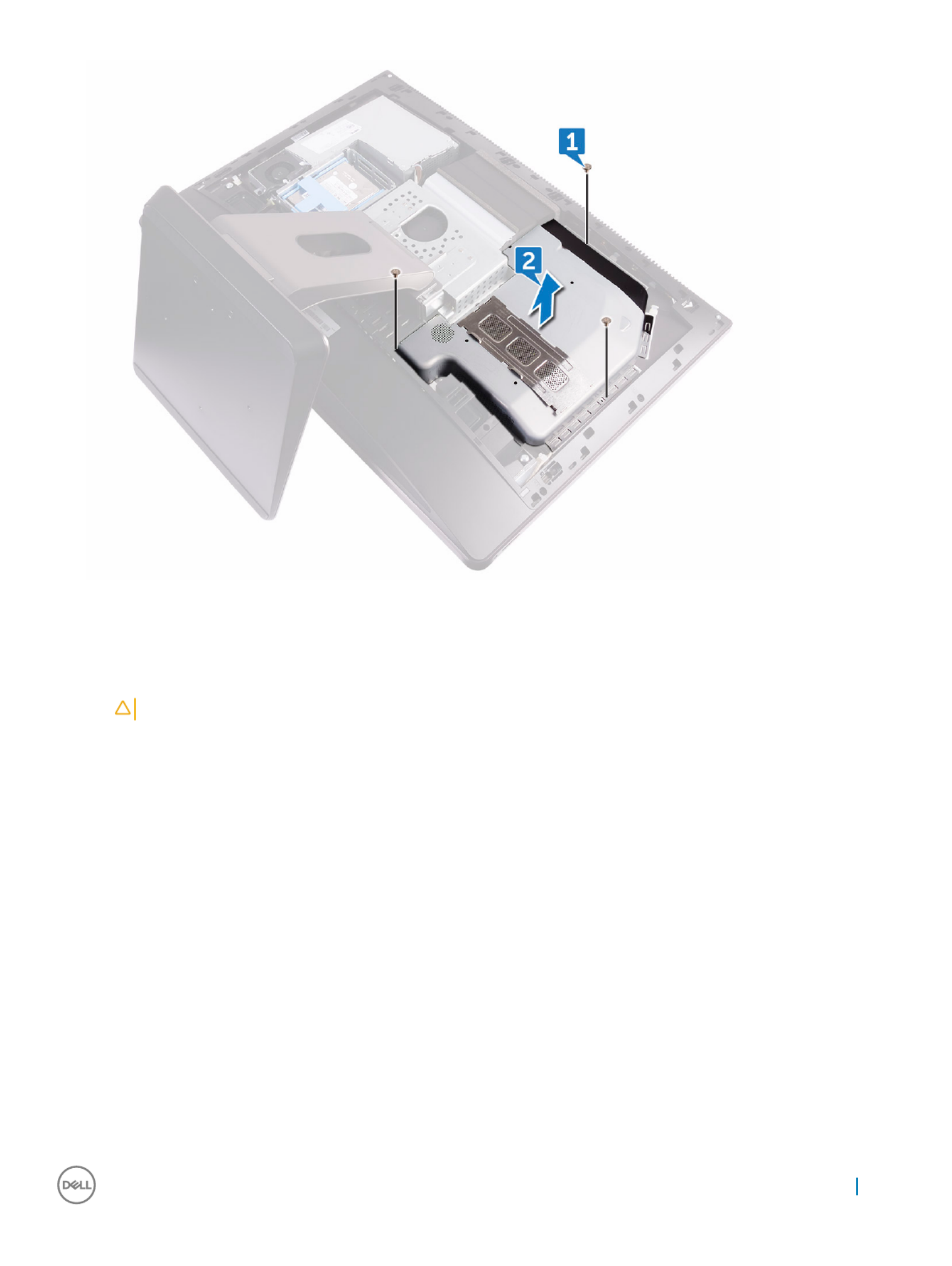
Installing s
Installing s
Installing s
Installing sInstalling syst
yst
yst
ystystem-boar
em-boar
em-boar
em-boarem-board shield
d shield
d shield
d shieldd shield
1 Align the screw holes on the system-board shield with the screw holes on the middle frame.
CA
CA
CA
CACAUTION
UTION
UTION
UTIONUTION
:
:
:
: : Make sur
Make sur
Make sur
Make surMake sure you do not damage the WLAN ant
e you do not damage the WLAN ant
e you do not damage the WLAN ant
e you do not damage the WLAN ante you do not damage the WLAN antenna when you place the system-boar
enna when you place the system-boar
enna when you place the system-boar
enna when you place the system-boarenna when you place the system-board shield.
d shield.
d shield.
d shield.d shield.
2 Replace the three screws (M3X4) that secure the system-board shield to the middle frame.
3 Install the:
aback cover
bUSB dongle-bay cover
4 Follow the procedure in After working inside your computer
M.2 PCIe SSD
M.2 PCIe SSD
M.2 PCIe SSD
M.2 PCIe SSD M.2 PCIe SSD
Remo
Remo
Remo
RemoRemoving M.2 PCIe SSD
ving M.2 PCIe SSD
ving M.2 PCIe SSD
ving M.2 PCIe SSDving M.2 PCIe SSD
1 Follow the procedure in Before working inside your computer.
2 Remove the:
aUSB dongle-bay cover
bback cover
csystem-board shield
3 Open the securing clip that secures the solid-state drive to the system board [1].
4 Slide and remove the solid-state drive from the solid-state drive slot [2].
Removing and installing components 19

aUSB dongle-bay cover
bback cover
csystem-board shield
3 Remove the four screws (M2X3) that secure the memory fan to the middle frame [1].
4 Gently lift the memory fan from the system board [2].
5 Disconnect the memory fan cable from the system board [3].
Installing memory f
Installing memory f
Installing memory f
Installing memory fInstalling memory fan
an
an
anan
1 Connect the memory fan cable to the system board.
2 Align the screw holes on the memory fan with the screw holes on the system board.
3 Replace the four screws (M2X3) that secure the memory fan to the system board.
4 Install the:
asystem-board shield
bback cover
cUSB dongle-bay cover
5 Follow the procedure in After working inside your computer.
Removing and installing components 21

Heat sink
Heat sink
Heat sink
Heat sinkHeat sink
Remo
Remo
Remo
RemoRemoving pr
ving pr
ving pr
ving prving processor hea
ocessor hea
ocessor hea
ocessor heaocessor heatsink f
tsink f
tsink f
tsink ftsink for s
or s
or s
or sor syst
yst
yst
ystystems with discr
ems with discr
ems with discr
ems with discrems with discre
e
e
eet
t
t
tte
e
e
e e
gr
gr
gr
grgraphics
aphics
aphics
aphicsaphics
NOTE:
NOTE:
NOTE:
NOTE: NOTE: Depending on the
Depending on the
Depending on the
Depending on the Depending on the con
con
con
conconguration
guration
guration
gurationguration you or
you or
you or
you or you order
der
der
derdered, the appearance o
ed, the appearance o
ed, the appearance o
ed, the appearance oed, the appearance of the processor hea
f the processor hea
f the processor hea
f the processor heaf the processor heatsink and the number of scr
tsink and the number of scr
tsink and the number of scr
tsink and the number of scrtsink and the number of screws may
ews may
ews may
ews may ews may
dier
dier
dier
dierdier.
.
.
..
NOTE:
NOTE:
NOTE:
NOTE: NOTE: The pr
The pr
The pr
The prThe procedur
ocedur
ocedur
ocedurocedure you see below is f
e you see below is f
e you see below is f
e you see below is fe you see below is for the remo
or the remo
or the remo
or the remoor the removal of heat
val of heat
val of heat
val of heatval of heatsink with discre
sink with discre
sink with discre
sink with discresink with discrete graphics
te graphics
te graphics
te graphicste graphics.
.
.
..
1 Follow the procedure in Before working inside your computer.
2 Remove the:
aUSB dongle-bay cover
bback cover
csystem-board shield
3 In sequential order (indicated on the heatsink), loosen eight captive screws that secure the processor heatsink to the system board [1].
4 Remove the screw (M3X4) that secures the processor heat-sink fan to the middle frame [2].
5 Lift the processor heatsink the system board [3].o
NOTE:
NOTE:
NOTE:
NOTE: NOTE: Comput
Comput
Comput
ComputComputers that support AMD Radeon Pr
ers that support AMD Radeon Pr
ers that support AMD Radeon Pr
ers that support AMD Radeon Prers that support AMD Radeon Pro WX7100 and AMD Radeon Pro WX
o WX7100 and AMD Radeon Pro WX
o WX7100 and AMD Radeon Pro WX
o WX7100 and AMD Radeon Pro WXo WX7100 and AMD Radeon Pro WX4150 graphics ar
4150 graphics ar
4150 graphics ar
4150 graphics ar4150 graphics are shipped with
e shipped with
e shipped with
e shipped with e shipped with
seven cap
seven cap
seven cap
seven capseven captive scre
tive scre
tive scre
tive scretive screws
ws
ws
wsws
Remo
Remo
Remo
RemoRemoving heat
ving heat
ving heat
ving heatving heatsink f
sink f
sink f
sink fsink for comput
or comput
or comput
or computor computers with in
ers with in
ers with in
ers with iners with int
t
t
ttegr
egr
egr
egregrat
at
at
atated graphics
ed graphics
ed graphics
ed graphicsed graphics
NOTE
NOTE
NOTE
NOTENOTE:
:
:
: : Depending on the
Depending on the
Depending on the
Depending on the Depending on the congur
congur
congur
congurconguration
ation
ation
ationation you or
you or
you or
you or you ordered, the appear
dered, the appear
dered, the appear
dered, the appeardered, the appearance of the pr
ance of the pr
ance of the pr
ance of the prance of the processor heat
ocessor heat
ocessor heat
ocessor heatocessor heat-sink and the number of scr
-sink and the number of scr
-sink and the number of scr
-sink and the number of scr-sink and the number of screws may
ews may
ews may
ews may ews may
dier
dier
dier
dierdier.
.
.
..
1 Follow the procedure in Before working inside your computer.
2 Remove the:
aUSB dongle-bay cover
bback cover
22 Removing and installing components

csystem-board shield
3 In sequential order (indicated on the heat sink), loosen the captive screws that secure the processor heat-sink to the system board.
4 Remove the screw (M3X4) that secures the processor heat-sink fan to the middle frame.
5 Lift the processor heat-sink the system board.o
Installing pr
Installing pr
Installing pr
Installing prInstalling processor heat
ocessor heat
ocessor heat
ocessor heatocessor heatsink
sink
sink
sinksink
1 Align the captive screws on the processor heat-sink with the screw holes on the system board.
2 In sequential order (indicated on the processor heat-sink), tighten the captive screws that secure the processor heat-sink to the
system board.
3 Replace the screw (M3X4) that secures the processor heat-sink fan to the middle frame.
4 Install the:
asystem-board shield
bback cover
cUSB dongle-bay cover
5 Follow the procedure in After working inside your computer
Pr
Pr
Pr
PrProcessor
ocessor
ocessor
ocessorocessor
Remo
Remo
Remo
RemoRemoving pr
ving pr
ving pr
ving prving processor
ocessor
ocessor
ocessorocessor
1 Follow the procedure in Before working inside your computer.
2 Remove the:
aUSB dongle-bay cover
bback cover
csystem-board shield
dprocessor heatsink
3 Press the release-lever down and then pull it outwards to release it from the securing tab [1].
4 Extend the release-lever completely to open the processor cover [2].
5 Gently lift the processor and remove it from the processor socket [3].
Removing and installing components 23
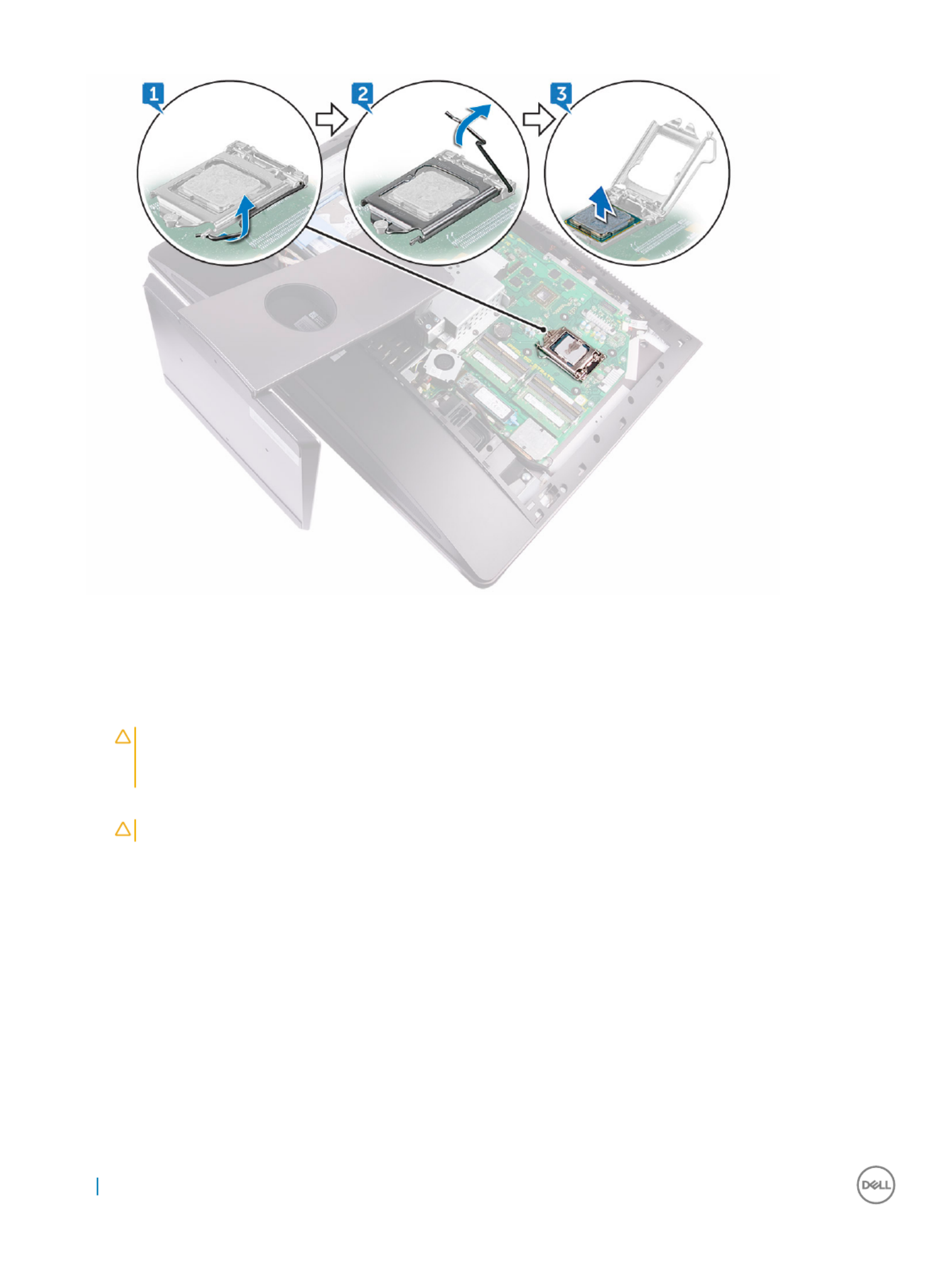
Installing pr
Installing pr
Installing pr
Installing prInstalling processor
ocessor
ocessor
ocessorocessor
1 Ensure that the release lever on the processor socket is fully extended in the open position.
CA
CA
CA
CACAUTION
UTION
UTION
UTIONUTION:
:
:
: : The pin-
The pin-
The pin-
The pin-The pin-1 corner of the pr
1 corner of the pr
1 corner of the pr
1 corner of the pr1 corner of the processor has a triangle that aligns with the triangle on the pin-
ocessor has a triangle that aligns with the triangle on the pin-
ocessor has a triangle that aligns with the triangle on the pin-
ocessor has a triangle that aligns with the triangle on the pin-ocessor has a triangle that aligns with the triangle on the pin-1 corner on the
1 corner on the
1 corner on the
1 corner on the 1 corner on the
pr
pr
pr
prprocessor socket. When the pr
ocessor socket. When the pr
ocessor socket. When the pr
ocessor socket. When the processor socket. When the processor is pr
ocessor is pr
ocessor is pr
ocessor is processor is properly sea
operly sea
operly sea
operly seaoperly seated, all f
ted, all f
ted, all f
ted, all fted, all four corners ar
our corners ar
our corners ar
our corners arour corners are aligned a
e aligned a
e aligned a
e aligned ae aligned at the same height. If one or mor
t the same height. If one or mor
t the same height. If one or mor
t the same height. If one or mort the same height. If one or more
e
e
e e
corners of the pr
corners of the pr
corners of the pr
corners of the prcorners of the processor ar
ocessor ar
ocessor ar
ocessor arocessor are higher than the o
e higher than the o
e higher than the o
e higher than the oe higher than the others, the pr
thers, the pr
thers, the pr
thers, the prthers, the processor is no
ocessor is no
ocessor is no
ocessor is noocessor is not seat
t seat
t seat
t seatt seated pr
ed pr
ed pr
ed pred properly
operly
operly
operlyoperly.
.
.
..
2 Align the notches on the processor with the tabs on the processor socket and place the processor in the processor socket.
CA
CA
CA
CACAUTION
UTION
UTION
UTIONUTION:
:
:
: : Ensur
Ensur
Ensur
EnsurEnsure that the pr
e that the pr
e that the pr
e that the pre that the processor
ocessor
ocessor
ocessorocessor-cov
-cov
-cov
-cov-cover not
er not
er not
er noter notch is positioned underneath the alignment post.
ch is positioned underneath the alignment post.
ch is positioned underneath the alignment post.
ch is positioned underneath the alignment post.ch is positioned underneath the alignment post.
3 When the processor is fully seated in the socket, close the processor cover.
4 Pivot the release-lever down and place it under the tab on the processor cover.
5 Install the:
aprocessor heat-sink.
bsystem-board shield
cback cover
dUSB dongle-bay cover
6 Follow the procedure in After working inside your computer
24 Removing and installing components

Coin cell bat
Coin cell bat
Coin cell bat
Coin cell batCoin cell batt
t
t
ttery
ery
ery
eryery
Remo
Remo
Remo
RemoRemoving coin-cell bat
ving coin-cell bat
ving coin-cell bat
ving coin-cell batving coin-cell batt
t
t
ttery
ery
ery
eryery
1 Follow the procedure in Before working inside your computer.
2 Remove the:
aUSB dongle-bay cover
bback cover
3 Using a plastic scribe, gently push the tab on the coin-cell battery socket until the battery pops up and then lift the coin-cell battery
o its slot on the system board.
Installing coin-cell ba
Installing coin-cell ba
Installing coin-cell ba
Installing coin-cell baInstalling coin-cell batt
tt
tt
ttttery
ery
ery
eryery
1 With the positive-side facing up, insert the coin-cell battery into the battery socket and press down the battery into place.
2 Install the:
asystem-board shield
bback cover
cUSB dongle-bay cover
3 Follow the procedure in After working inside your computer
Removing and installing components 25

WL
WL
WL
WLWLAN car
AN car
AN car
AN carAN card
d
d
dd
Remo
Remo
Remo
RemoRemoving wir
ving wir
ving wir
ving wirving wireless car
eless car
eless car
eless careless card
d
d
dd
1 Remove the:
aUSB dongle-bay cover
bback cover
csystem-board shield
2 Remove the antenna cables from the securing clip [1].
3 Remove the two screws (M2X2.5) that secure the wireless-card shield to the system board [2].
4 Lift the wireless-card shield the system board [3].o
5 Remove the screw (M2X2.5) that secures the wireless-card bracket and the wireless card to the system board [4].
6 Lift the wireless-card bracket the wireless card [5].o
7 Disconnect the antenna cables from the wireless card [6].
8 Slide and remove the wireless card out of the wireless-card slot [7].
26 Removing and installing components

Installing the wir
Installing the wir
Installing the wir
Installing the wirInstalling the wireless car
eless car
eless car
eless careless card
d
d
dd
CA
CA
CA
CACAUTION:
UTION:
UTION:
UTION: UTION: T
T
T
TT
o av
o av
o av
o avo avoid damaging the wireless car
oid damaging the wireless car
oid damaging the wireless car
oid damaging the wireless caroid damaging the wireless card, do not place an
d, do not place an
d, do not place an
d, do not place and, do not place any cables under it.
y cables under it.
y cables under it.
y cables under it.y cables under it.
1 Align the notch on the wireless card with the tab on the wireless-card slot and slide the wireless card into the wireless-card slot.
2 Route the antenna cable through the routing guide.
3 Connect the antenna cables to the wireless card.
The following table provides the antenna-cable color scheme for the wireless card supported by your computer:
T
T
T
TT
able 1. : Wir
able 1. : Wir
able 1. : Wir
able 1. : Wirable 1. : Wirelesscard colour scheme
elesscard colour scheme
elesscard colour scheme
elesscard colour schemeelesscard colour scheme
Connect
Connect
Connect
ConnectConnectors on the wir
ors on the wir
ors on the wir
ors on the wirors on the wireless card
eless card
eless card
eless cardeless card Ant
Ant
Ant
AntAntenna-cable color
enna-cable color
enna-cable color
enna-cable colorenna-cable color
Main (white triangle) White
Auxiliary (black triangle) Black
4 Press down the other end of the wireless card and align the screw hole on the wireless-card bracket and wireless card with the screw
hole on the system board.
5 Replace the screw (M2X2.5) that secures the wireless-card bracket and the wireless card to the system board.
6 Align the screw holes on the wireless-card shield with the screw holes on the system board.
7 Replace the two screws (M2X2.5) that secure the wireless-card shield to system board.
8 Route the antenna cables through the securing clip.
9 Install the:
asystem-board shield
bback cover
cUSB dongle-bay cover
10 Follow the procedure in After working inside your computer
St
St
St
StStand
and
and
andand
Remo
Remo
Remo
RemoRemoving stand
ving stand
ving stand
ving standving stand
1 Follow the procedure in Before working inside your computer.
2 Remove the:
aUSB dongle-bay cover
bback cover
3 Remove the six screws (M4X6) that secure the stand to the middle frame [1].
4 Lift the stand o the computer [2].
Removing and installing components 27

Installing st
Installing st
Installing st
Installing stInstalling stand
and
and
andand
1 Align the screw holes on the stand with the screw holes on the middle frame.
2 Replace the six screws (M4X6) that secure the stand to the middle frame.
3 Install the:
aback cover
bUSB dongle-bay cover
4 Follow the procedure in After working inside your computer
Syst
Syst
Syst
SystSystem f
em f
em f
em fem fan
an
an
anan
Remo
Remo
Remo
RemoRemoving syst
ving syst
ving syst
ving systving system f
em f
em f
em fem fan
an
an
anan
1 Follow the procedure in Before working inside your computer.
2 Remove the:
aUSB dongle-bay cover
bback cover
cstand
dsystem-board shield
3 Remove the power-supply unit cable from the routing guides on the system fan [1].
4 Disconnect the power-supply unit cable from its connector on the system board [2]..
28 Removing and installing components

5 Disconnect the system fan cable from the system board [1].
6 Remove the four screws (M3X4) that secure the system fan to the middle frame [2].
7 Lift the system fan along with its cable the middle frame [3].o
Removing and installing components 29

Installing s
Installing s
Installing s
Installing sInstalling syst
yst
yst
ystystem f
em f
em f
em fem fan
an
an
anan
1 Align the screw holes on the system fan with the screw holes on the middle frame.
2 Replace the four screws (M3X4) that secure the system fan to the middle frame.
3 Connect the system fan cable to the system board.
4 Connect the power-supply unit cable to its connector on the system board.
5 Route the power-supply unit cable through the routing guides on the system fan.
6 Install the:
asystem-board shield.
bstand
cback cover
dUSB dongle-bay cover
7 Follow the procedure in After working inside your computer
P
P
P
PPo
o
o
oower supply unit
wer supply unit
wer supply unit
wer supply unitwer supply unit
Remo
Remo
Remo
RemoRemoving pow
ving pow
ving pow
ving powving power supply unit
er supply unit
er supply unit
er supply uniter supply unit
1 Follow the procedure in Before working inside your computer.
2 Remove the:
30 Removing and installing components
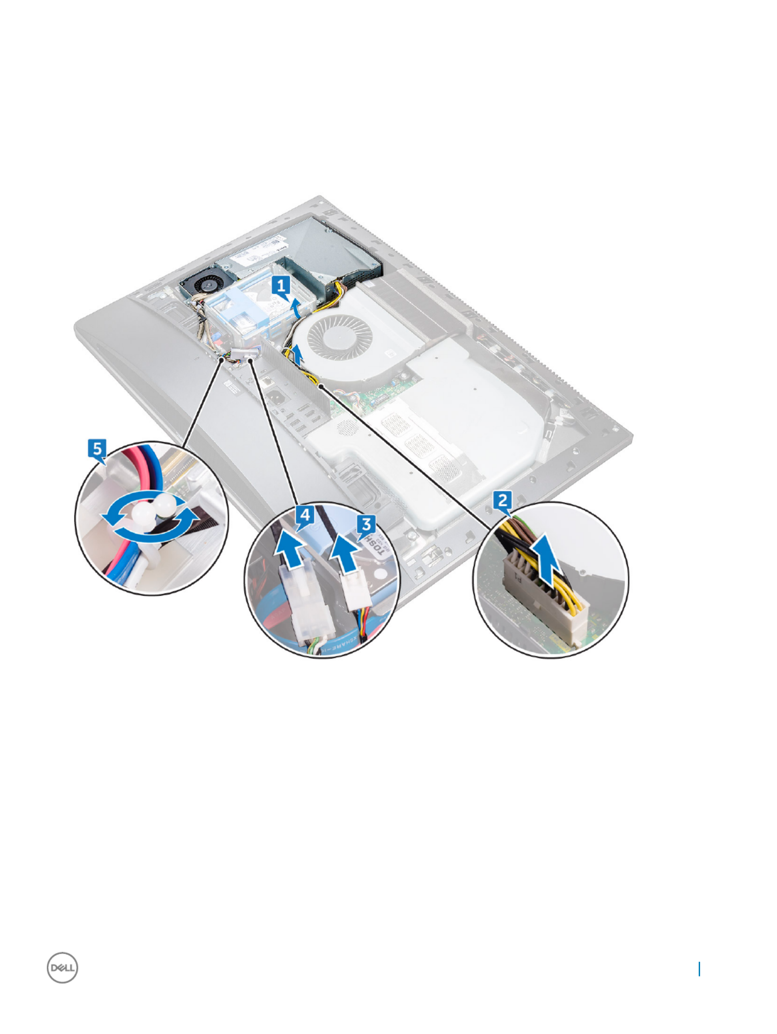
aUSB dongle-bay cover
bback cover
cstand
3 Remove the power-supply unit cable from the routing guides on the system fan [1].
4 Disconnect the power-supply unit cable from its connector on the system board [2].
5 Press the securing clip to release the power-supply indicator cable from its connector [3].
6 Press the securing clip to release the power-supply fan cable from its connector [4].
7 Open the securing clips and release the cables [5].
8 Remove the screws (M3X4) that secure the power-supply unit to the middle cover [6].ve
9 Lift the power-supply unit with the cable o the middle cover [7].
Removing and installing components 31

Installing po
Installing po
Installing po
Installing poInstalling power supply unit
wer supply unit
wer supply unit
wer supply unitwer supply unit
1 Align the screw holes on the power-supply unit with the screw holes on the middle cover.
2 Replace the screws (M3X4) that secure the power-supply unit to the middle cover.ve
3 Route the cables through the guide and close the clip to secure the cables.
4 Connect the power-supply indicator cable and power-supply fan cable to their respective connectors.
5 Route the power-supply unit cable through the routing guides on system fan.
6 Connect the power-supply unit cable to its connector on the system board.
7 Install the:
aback cover
bUSB dongle-bay cover
cstand
8 Follow the procedure in After working inside your computer
32 Removing and installing components

Inner fr
Inner fr
Inner fr
Inner frInner frame
ame
ame
ameame
Remo
Remo
Remo
RemoRemoving inner fr
ving inner fr
ving inner fr
ving inner frving inner frame
ame
ame
ameame
1 Follow the procedure in Before working inside your computer.
2 Remove the:
aUSB dongle-bay cover
bback cover
cstand
3 Remove 20 screws (M3X4) that secure the inner frame to the middle frame.
4 Gently pry the inner frame from the sides and lift it the middle frame.(2)o
Removing and installing components 33

Installing inner fr
Installing inner fr
Installing inner fr
Installing inner frInstalling inner frame
ame
ame
ameame
1 Align the screw holes on the inner frame with the screw holes on the middle frame.
2 Replace 20 screws (M3X4) that secure the inner frame to the middle frame.
3 Install the:
astand
bback cover
cUSB dongle-bay cover
4 Follow the procedure in After working inside your computer
Built
Built
Built
BuiltBuilt-in self t
-in self t
-in self t
-in self t-in self test but
est but
est but
est butest butt
t
t
tton
on
on
onon
Remo
Remo
Remo
RemoRemoving built-in self t
ving built-in self t
ving built-in self t
ving built-in self tving built-in self test butt
est butt
est butt
est buttest button
on
on
onon
1 Follow the procedure in Before working inside your computer.
2 Remove the:
aUSB dongle-bay cover
bback cover
cstand
dinner frame
3 Remove the power-button cable from the routing guide on the power-button board shield [1].
34 Removing and installing components
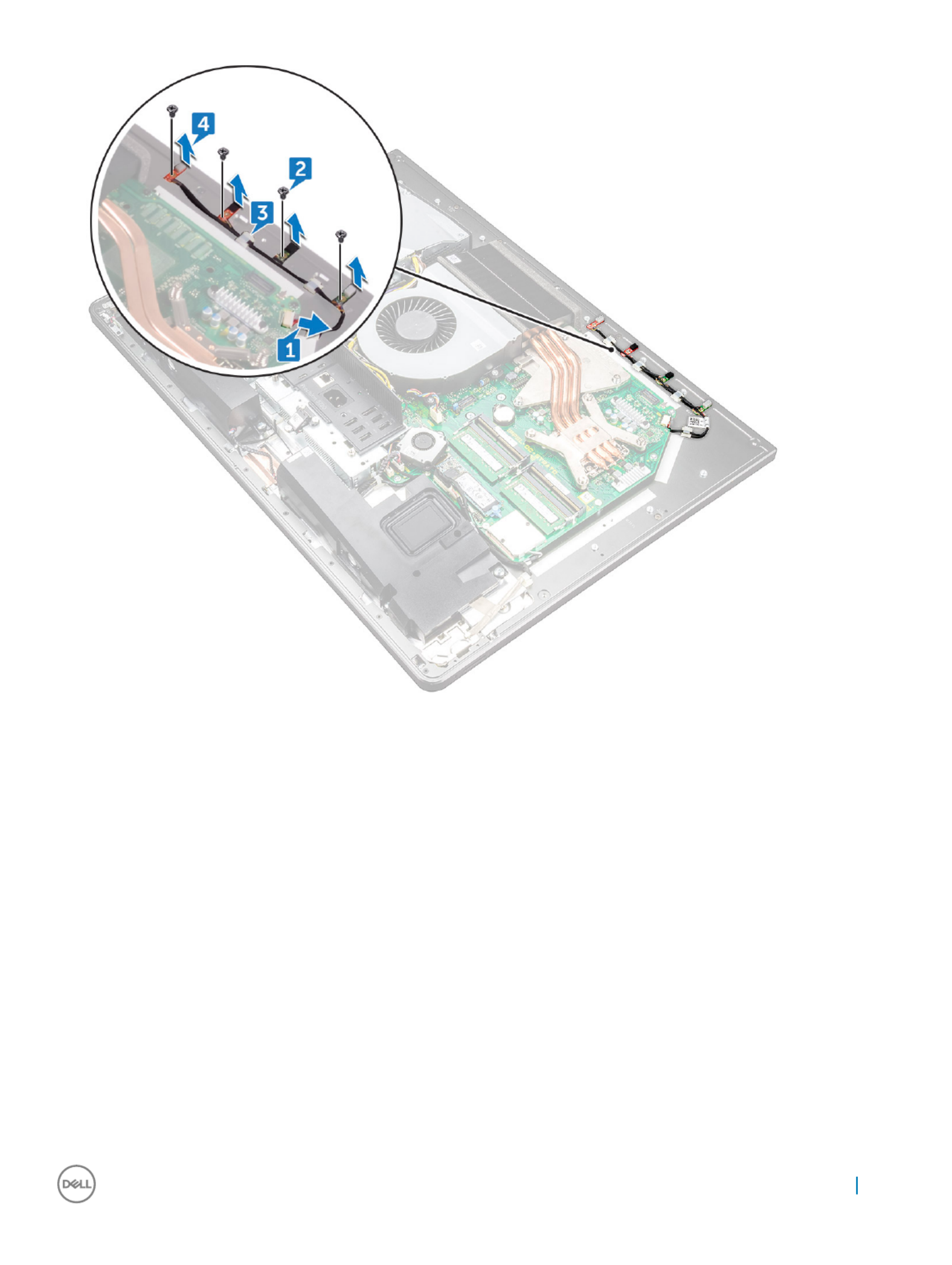
Installing micr
Installing micr
Installing micr
Installing micrInstalling microphone
ophone
ophone
ophoneophone
1 Align the microphone modules (4) with their slots on the middle frame.
2 Route the cable through the routing guides on the middle frame.
3 Replace the four screws (M2X2.2) that secure the microphone module to the middle frame.
4 Connect the microphone cable to the system board.
5 Install the:
ainner frame
bstand
csystem-board shield
dback cover
eUSB dongle-bay cover
6 Follow the procedure in After working inside your computer
Removing and installing components 37

8 Remove .USB-dongle port
9 Remove the Diagnostic light button board.
Installing I/
Installing I/
Installing I/
Installing I/Installing I/O panel
O panel
O panel
O panelO panel
1 Replace the Diagnostic light button board.
2 Replace .USB-dongle port
3 Connect the USB-dongle cable to the system board.
4 Align the screw holes on the I/O-board panel with the screw holes on the middle frame.
5 Replace the four screws (M3X4) that secure the I/O panel to the middle frame and system board.
6 Connect the diagnostic button and light cable.
7 Connect the power-button cable.
8 Install the:
ainner frame
bstand
csystem-board shield
dback cover
eUSB dongle-bay cover
9 Follow the procedure in After working inside your computer
Removing and installing components 39

USB-dongle port
USB-dongle port
USB-dongle port
USB-dongle portUSB-dongle port
Remo
Remo
Remo
RemoRemoving USB-dongle port
ving USB-dongle port
ving USB-dongle port
ving USB-dongle portving USB-dongle port
1 Follow the procedure in Before working inside your computer.
2 Remove the:
aUSB dongle-bay cover
bback cover
cstand
dinner frame
esystem-board shield.
fI/O panel
3 Remove the three screws (M3X4) that secure the USB dongle port to the I/O panel.
4 Remove the USB dongle port cable from the routing guide on I/O panel [2].
5 Remove the USB dongle port from the I/O panel. [3]
40 Removing and installing components

Installing USB-dongle port
Installing USB-dongle port
Installing USB-dongle port
Installing USB-dongle portInstalling USB-dongle port
1 Route the USB dongle port cable into the slot on I/O panel .
2 Route the USB dongle port cable through the routing guide on I/O panel .
3 Align the screw holes on the USB dongle port with the screw holes on the I/O panel.
4 Replace the three screws (M3X4) that secure the USB dongle port to the I/O panel.
5 Install the:
aI/O panel
bsystem-board shield.
cinner frame
dstand
eback cover
fUSB dongle-bay cover
6 Follow the procedure in After working inside your computer
Removing and installing components 41

Diagnostic light and but
Diagnostic light and but
Diagnostic light and but
Diagnostic light and butDiagnostic light and butt
t
t
tton boar
on boar
on boar
on boaron board
d
d
dd
Remo
Remo
Remo
RemoRemoving the diagnostic light and but
ving the diagnostic light and but
ving the diagnostic light and but
ving the diagnostic light and butving the diagnostic light and butt
t
t
tton boar
on boar
on boar
on boaron board
d
d
d d
1 Follow the procedure in Before working inside your computer.
2 Remove the:
aUSB dongle-bay cover
bback cover
cstand
dsystem-board shield.
einner frame
fI/O panel
3 Spread apart the securing tabs to release the I/O-panel bracket from the I/O panel.
4 Lift the I/O-panel bracket the I/O panel.o
42 Removing and installing components

5 Remove the screw that secures the power diagnostic button and light board to the I/O-panel bracket [1].
6 Lift the power diagnostic button and light board the I/O-panel bracket [2].o
Removing and installing components 43

Installing diagnostic ligh
Installing diagnostic ligh
Installing diagnostic ligh
Installing diagnostic lighInstalling diagnostic light and butt
t and butt
t and butt
t and buttt and button boar
on boar
on boar
on boaron board
d
d
dd
1 Align the screw holes on power diagnostic button and light board to the screw holes on the I/O-panel bracket.
2 Replace the screw that secures the power diagnostic button and light board to the I/O-panel bracket.
3 Align the tabs on the I/O-panel bracket with the slots on the I/O panel and snap the I/O-panel bracket in place.
4 Install the:
aI/O panel
binner frame
csystem-board shield.
dstand
eback cover
fUSB dongle-bay cover
5 Follow the procedure in After working inside your computer
Drive cage
Drive cage
Drive cage
Drive cageDrive cage
Remo
Remo
Remo
RemoRemoving HDD
ving HDD
ving HDD
ving HDDving HDD/SSD cage
/SSD cage
/SSD cage
/SSD cage/SSD cage
1 Follow the procedure in Before working inside your computer.
2 Remove the:
aUSB dongle-bay cover
bback cover
cstand
dhard drive
esystem-board shield.
fI/O panel
3 Remove the cable from the routing guide on drive cage [1].
4 Open the securing clips and release the HDD/SSD cables [2].
5 Disconnect the HDD/SSD cable from the system board [3].
6 Disconnect the HDD/SSD data cables from the system board [4].
44 Removing and installing components

7 Remove the four screws (M3X4) that connect the drive cage to the middle frame [1].
8 Lift the hard-drive cage o the middle frame [2].
Removing and installing components 45
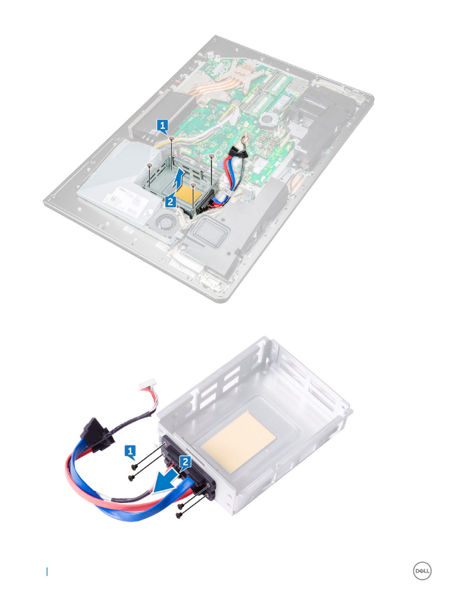
9 Remove the four screws (M2X3) that connect the interposer to the hard-drive cage [1].
10 Remove the interposer from the hard-drive cage [2].
46 Removing and installing components

Installing HDD
Installing HDD
Installing HDD
Installing HDDInstalling HDD/
/
/
//SSD cage
SSD cage
SSD cage
SSD cageSSD cage
1 Align the screw holes on the interposer with the screw holes on the drive cage.
2 Replace the four screws (M2X3) that connect the interposer to the drive cage.
3 Align the screw holes on the hard-drive cage to the screw holes on the middle frame.
4 Replace the four screws (M3X4) that secure the drive cage to the middle frame.
5 Connect the HDD/SSD cables and the HDD/SSD power cable to the system board.
NOTE:
NOTE:
NOTE:
NOTE: NOTE: Connec
Connec
Connec
ConnecConnect the blue-colored cable a
t the blue-colored cable a
t the blue-colored cable a
t the blue-colored cable at the blue-colored cable at the top and r
t the top and r
t the top and r
t the top and rt the top and red-colored cable t
ed-colored cable t
ed-colored cable t
ed-colored cable ted-colored cable to the bott
o the bott
o the bott
o the botto the bottom of the drive cage
om of the drive cage
om of the drive cage
om of the drive cageom of the drive cage.
.
.
..
6 Route the cables through the guide and close the clip to secure the cables.
7 Install the:
aI/O panel
bsystem-board shield.
cstand
dhard drive
eback cover
fUSB dongle-bay cover
8 Follow the procedure in After working inside your computer
Conv
Conv
Conv
ConvConvert
ert
ert
erterter boar
er boar
er boar
er boarer board
d
d
dd
Remo
Remo
Remo
RemoRemoving conv
ving conv
ving conv
ving convving convert
ert
ert
erterter boar
er boar
er boar
er boarer board
d
d
dd
1 Follow the procedure in Before working inside your computer.
2 Remove the:
aUSB dongle-bay cover
bback cover
cstand
dsystem-board shield
einner frame
fI/O panel
3 Disconnect the left backlight power cable from the converter board [1].
4 Disconnect the converter-board cable from the converter board [2].
5 Disconnect the right backlight power cable from the converter board [3].
Removing and installing components 47
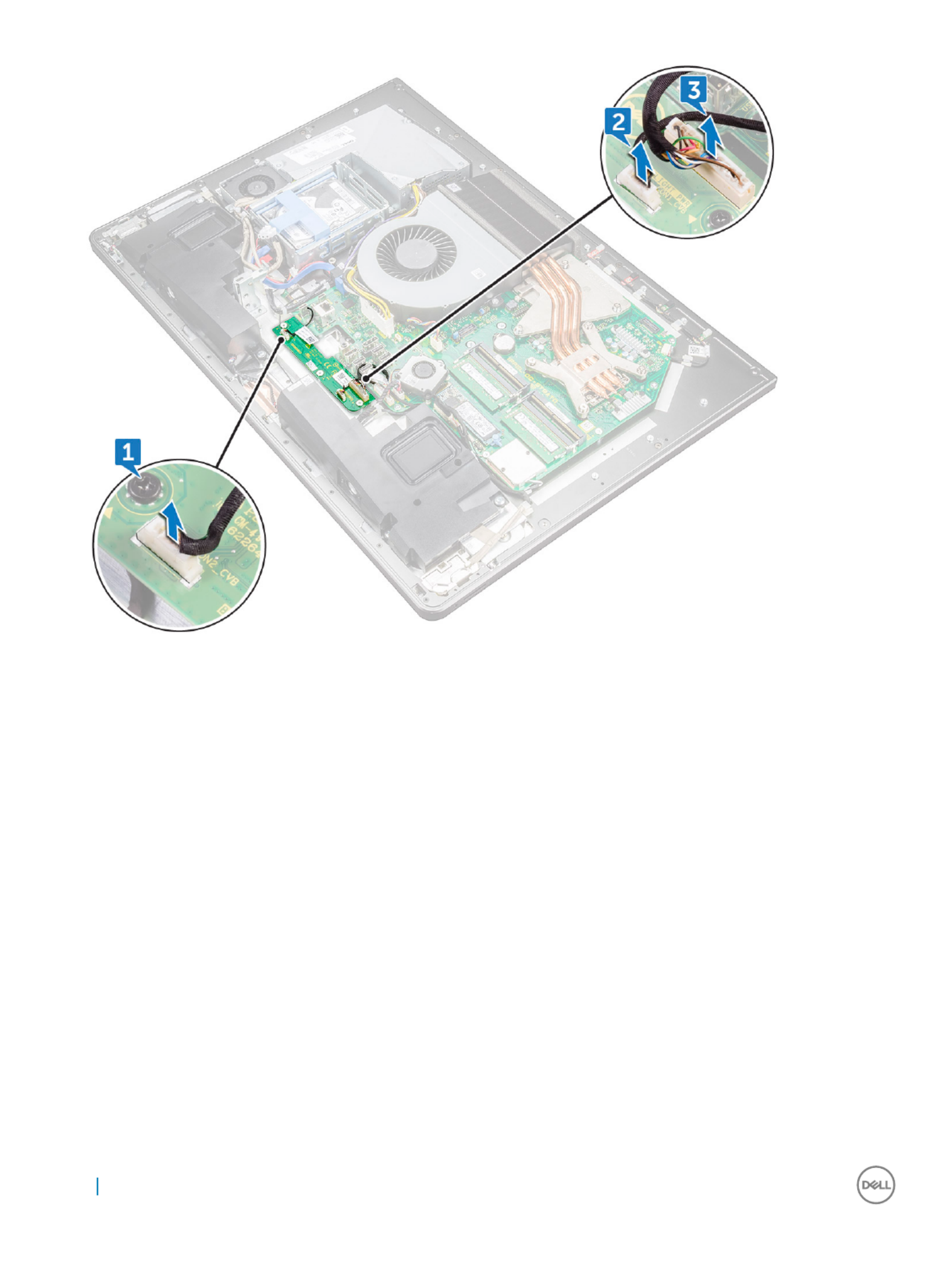
6 Remove the three screws (M3X4) that secure the converter board to the middle frame [1].
7 Lift the converter board o the middle frame [2].
48 Removing and installing components
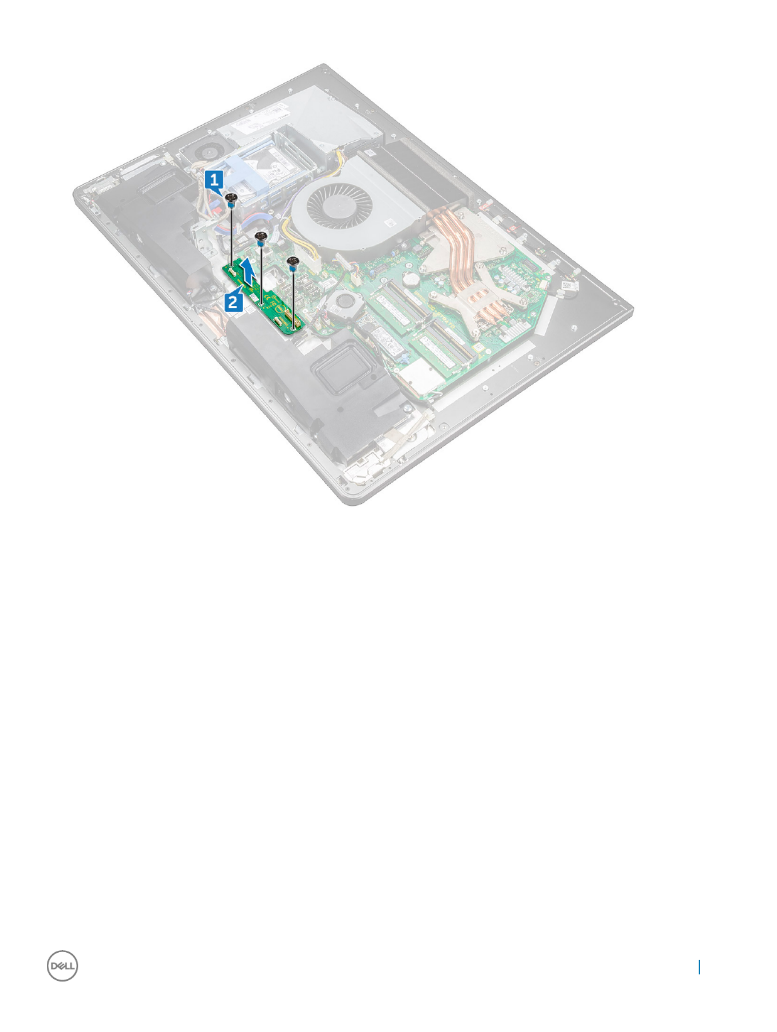
Installing con
Installing con
Installing con
Installing conInstalling convert
vert
vert
vertverter boar
er boar
er boar
er boarer board
d
d
dd
1 Align the screw holes on the converter board with the screw holes on the middle frame.
2 Replace the three screws (M3X4) that secure the converter board to the middle frame.
3 Connect the converter-board cable to the converter board.
4 Connect the backlight power cables to the converter board.
5 Install the:
aI/O panel
binner frame
csystem-board shield.
dstand
eback cover
fUSB dongle-bay cover
6 Follow the procedure in After working inside your computer
Removing and installing components 49

Speaker
Speaker
Speaker
SpeakerSpeaker
Remo
Remo
Remo
RemoRemoving speaker
ving speaker
ving speaker
ving speakerving speakers
s
s
ss
1 Follow the procedure in Before working inside your computer.
2 Remove the:
aUSB dongle-bay cover
bback cover
csystem-board shield
dstand
einner frame
3 Disconnect the speaker cable from the system board and release it from the routing guides on middle frame [1] [2].
4 Remove the eight screws (M3x4) that secure the speakers to the middle frame [1].
50 Removing and installing components

5 Lift the speakers along with the cable the middle frame [2].o
Installing speak
Installing speak
Installing speak
Installing speakInstalling speaker
er
er
erer
1 Align the screw holes on the speakers with the screw holes on the middle frame.
2 Replace the eight screws (M3x4) that secure the speakers to the middle frame.
3 Route the cable through the routing guides on middle frame and connect the speaker cable to the system board.
4 Install the:
ainner frame
bstand
csystem-board shield
dback cover
eUSB dongle-bay cover
Removing and installing components 51

P
P
P
PPow
ow
ow
owower butt
er butt
er butt
er butter button boar
on boar
on boar
on boaron board
d
d
dd
Remo
Remo
Remo
RemoRemoving pow
ving pow
ving pow
ving powving power
er
er
erer-butt
-butt
-butt
-butt-button boar
on boar
on boar
on boaron board
d
d
dd
NOTE:
NOTE:
NOTE:
NOTE: NOTE: No
No
No
NoNote the r
te the r
te the r
te the rte the routing of the cable as you r
outing of the cable as you r
outing of the cable as you r
outing of the cable as you routing of the cable as you remove it so that you can r
emove it so that you can r
emove it so that you can r
emove it so that you can remove it so that you can rer
er
er
ereroute it corr
oute it corr
oute it corr
oute it corroute it correctly after y
ectly after y
ectly after y
ectly after yectly after you replace the pow
ou replace the pow
ou replace the pow
ou replace the powou replace the power-but
er-but
er-but
er-buter-button
ton
ton
ton ton
boar
boar
boar
boarboard.
d.
d.
d.d.
1 Follow the procedure in Before working inside your computer.
2 Remove the:
aUSB dongle-bay cover
bback cover
cstand
dinner frame
3 Remove the power-button cable from the routing guide on the power-button board shield [1].
4 Remove the two screws (M2X3) that secure the power-button board shield to the middle frame [2].
5 Slide and remove the power-button board shield the middle frame [3].o
6 Lift the power-button board the slot on the middle frame [4].o
7 Disconnect the power-button board cable from the power-button board [5].
8 Disconnect the Display Built-in Self Test button cable from the power-button board [6].
52 Removing and installing components
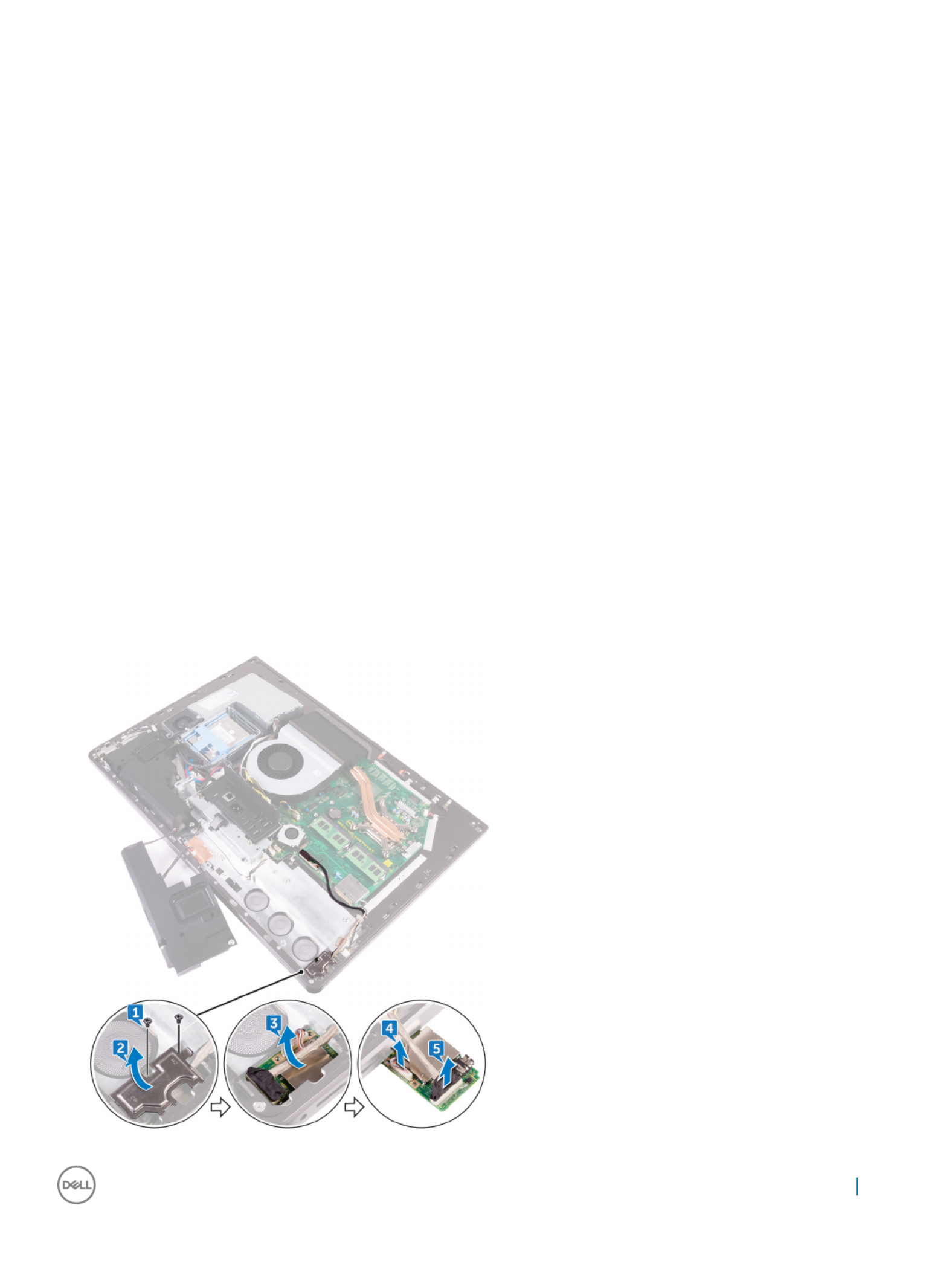
Installing po
Installing po
Installing po
Installing poInstalling power but
wer but
wer but
wer butwer butt
t
t
tton boar
on boar
on boar
on boaron board
d
d
dd
1 Connect the power-button board cable and Display Built-in Self Test button cable to the power-button board.
2 Align the power-button board to the slot on the middle frame and place the power-button board on the middle frame.
3 Align the screw holes on power-button board shield to the screw holes on middle frame.
4 Replace the two screws (M2X3) that secures the power-button board shield to middle frame.
5 Route the power-button cable through the routing guides on the power-button board shield.
Media car
Media car
Media car
Media carMedia card r
d r
d r
d rd reader
eader
eader
eadereader
Remo
Remo
Remo
RemoRemoving media-car
ving media-car
ving media-car
ving media-carving media-card r
d r
d r
d rd reader
eader
eader
eadereader
1 Follow the procedure in Before working inside your computer.
2 Remove the:
aUSB dongle-bay cover
bback cover
cstand
dinner frame
espeakers
3 Remove two screws (M2X3) that secure the media-card reader shield to the middle frame [1].
4 Lift the media-card reader shield o the middle frame [2].
5 Slide and lift the media-card from the slot on the middle frame [3].o
6 Disconnect the media-card reader cable from the media-card [4].
7 Disconnect the audio cable from the media-card [5].
Removing and installing components 53

Installing media car
Installing media car
Installing media car
Installing media carInstalling media card r
d r
d r
d rd reader
eader
eader
eadereader
1 Connect the audio cable to the media card.
2 Connect the media-card reader cable to the media-card.
3 Align the media-card reader to the slot on the middle frame.
4 Align the screw hole on the media-card reader shield to the screw hole on the middle frame.
5 Replace the two screws (M2X3) that secure the media-card reader shield to the middle frame.
6 Install the:
aspeakers.
binner frame
cstand
dback cover
eUSB dongle-bay cover
7 Follow the procedure in After working inside your computer
Camer
Camer
Camer
CamerCamera
a
a
aa
Remo
Remo
Remo
RemoRemoving camer
ving camer
ving camer
ving camerving camera
a
a
aa
1 Follow the procedure in Before working inside your computer.
2 Remove the:
aUSB dongle-bay cover
bback cover
cstand
dinner frame
espeakers
3 Remove the two screws (M2X3) that secure the camera assembly to the middle frame [1].
4 Remove the camera cable from the routing guide on the middle frame [2].
5 Lift the metal foil and turn the camera assembly over [3].
6 Unrote the cable from the clip and disconnect the camera cable from the camera assembly [4]
54 Removing and installing components

Syst
Syst
Syst
SystSystem boar
em boar
em boar
em boarem board
d
d
dd
Remo
Remo
Remo
RemoRemoving syst
ving syst
ving syst
ving systving system boar
em boar
em boar
em boarem board
d
d
dd
NOTE:
NOTE:
NOTE:
NOTE: NOTE: T
T
T
TT
o av
o av
o av
o avo avoid any poten
oid any poten
oid any poten
oid any potenoid any potential damage to the cables, ensur
tial damage to the cables, ensur
tial damage to the cables, ensur
tial damage to the cables, ensurtial damage to the cables, ensure to r
e to r
e to r
e to re to release them from the r
elease them from the r
elease them from the r
elease them from the release them from the routing guides.
outing guides.
outing guides.
outing guides.outing guides.
1 Follow the procedure in Before working inside your computer.
2 Remove the:
aUSB dongle-bay cover
bback cover
cmemory modules
dstand
esystem fan
finner frame
gsystem-board shield.
hI/O panel
iprocessor heat-sink
jprocessor.
kcoin-cell battery
lmemory fan
mwireless card
nsolid-state drive.
3 Using the pull tab, disconnect the display cable from the system board [3].
4 Disconnect the camera cable from the system board [2].
5 Using the pull tab, disconnect the USB-connection cable from the system board [3].
6 Disconnect the hard-drive power cable from the system board. [4]
7 Disconnect the hard-drive data cables from the system board [5].
56 Removing and installing components
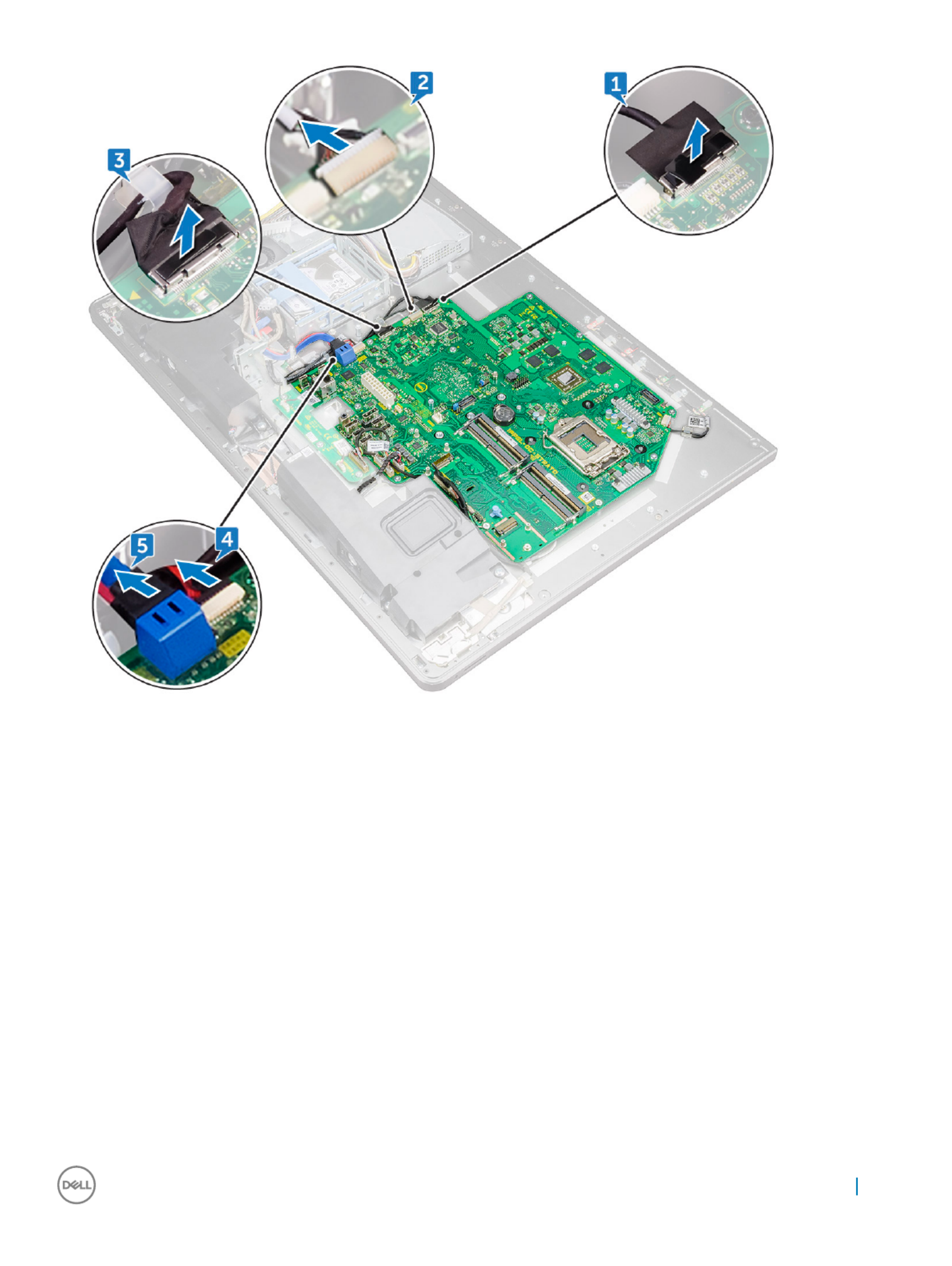
8 Disconnect the speaker cable from the system board [1].
9 Disconnect the converter-board cable from the system board [2].
10 Using the pull tab, disconnect the media-card reader cable from the system board [3].
11 Disconnect the audio cable from the system board [4].
12 Remove the screw (M3X4) that secures the media-card reader cable and audio cable to the system board [5]
13 Disconnect the microphone cable from the system board [6]
Removing and installing components 57

14 Remove the 12 screws (M3X4) that secure the system board to the middle frame [1].
15 Lift the system board the middle frame [2]o
58 Removing and installing components

lmemory modules
mback cover
nUSB dongle-bay cover
7 Follow the procedure in After working inside your computer
Syst
Syst
Syst
SystSystem boar
em boar
em boar
em boarem board callouts
d callouts
d callouts
d callouts d callouts
Figur
Figur
Figur
FigurFigure 1. Syst
e 1. Syst
e 1. Syst
e 1. Syste 1. System boar
em boar
em boar
em boarem board callouts
d callouts
d callouts
d calloutsd callouts
1 password clear jumper 2 coin-cell battery connector
3 microphone cable connector 4 processor socket
5 memory module slot 6 system fan connector
7 wireless-card slot 8 audio-cable connector
9 media-card connector 10 SSD-card connector (M.2)
11 speaker cable connector 12 converter-board cable connector
13 memory-fan cable connector 14 USB 3.0 ports (4)
15 HDMI port 16 Line-out port
17 displayport 18 network port
19 Thunderbolt 3 (USB Type-C) port 20 Thunderbolt 3 (USB Type-C) port
21 power-supply unit cable connector 22 SATA-card slot
60 Removing and installing components

23 SATA power connector 24 USB connector
25 CMOS clear jumper 26 side USB connector
27 touch cable connector 28 camera connector
29 display connector
Displa
Displa
Displa
DisplaDisplay assembly
y assembly
y assembly
y assemblyy assembly
Remo
Remo
Remo
RemoRemoving displa
ving displa
ving displa
ving displaving display assembly
y assembly
y assembly
y assemblyy assembly
1 Follow the procedure in Before working inside your computer.
2 Remove the:
aUSB dongle-bay cover
bback cover
cmemory modules
dstand
esystem fan
finner frame
gsystem-board shield
hI/O panel
iprocessor heat-sink
jprocessor
kcoin-cell battery
lmemory fan
mwireless card
nsolid-state drive
osystem board
3 Press the tabs on the cable to release it from the connector [1].
4 Disconnect the cable from its slot on the middle frame [2]
5 Press the tabs on the backlight cable [3].
6 Disconnect the backlight cable from its slot on the middle frame [4].
7 Open the latch and disconnect the display cable from its slot on the middle frame.
8 Lift the display cable the middle frame.o
Removing and installing components 61

We are left with the display assembly.
Installing displa
Installing displa
Installing displa
Installing displaInstalling display assembly
y assembly
y assembly
y assemblyy assembly
1 Open the latch and connect the display cable to its slot on the middle frame.
2 Connect the backlight cable to its slot on the middle frame.
3 Connect the converter-board cable to its slot on the middle frame.
4 Install the:
asystem board
bsolid-state drive.
cwireless card
dmemory fan
ecoin-cell battery
fprocessor.
gprocessor heat-sink
hI/O panel
isystem-board shield.
jinner frame
ksystem fan
lstand
62 Removing and installing components

mmemory modules
nback cover
oUSB dongle-bay cover
5 Follow the procedure in After working inside your computer
Middle fr
Middle fr
Middle fr
Middle frMiddle frame
ame
ame
ameame
Remo
Remo
Remo
RemoRemoving middle fr
ving middle fr
ving middle fr
ving middle frving middle frame
ame
ame
ameame
NOTE:
NOTE:
NOTE:
NOTE: NOTE: The f
The f
The f
The fThe following st
ollowing st
ollowing st
ollowing stollowing steps ar
eps ar
eps ar
eps areps are applicable only f
e applicable only f
e applicable only f
e applicable only fe applicable only for non-t
or non-t
or non-t
or non-tor non-touch syst
ouch syst
ouch syst
ouch systouch systems.
ems.
ems.
ems.ems.
NOTE:
NOTE:
NOTE:
NOTE: NOTE: The middle fr
The middle fr
The middle fr
The middle frThe middle frame can be r
ame can be r
ame can be r
ame can be rame can be remov
emov
emov
emovemoved by r
ed by r
ed by r
ed by red by removing the f
emoving the f
emoving the f
emoving the femoving the following componen
ollowing componen
ollowing componen
ollowing componenollowing components only
ts only
ts only
ts onlyts only. In this scenario, the user has t
. In this scenario, the user has t
. In this scenario, the user has t
. In this scenario, the user has t. In this scenario, the user has to r
o r
o r
o ro remove 15
emove 15
emove 15
emove 15 emove 15
scr
scr
scr
scrscrews that secur
ews that secur
ews that secur
ews that securews that secure the middle fr
e the middle fr
e the middle fr
e the middle fre the middle frame t
ame t
ame t
ame tame to the display panel and the speak
o the display panel and the speak
o the display panel and the speak
o the display panel and the speako the display panel and the speaker bez
er bez
er bez
er bezer bezel, including one scr
el, including one scr
el, including one scr
el, including one screl, including one screw fr
ew fr
ew fr
ew frew from the media-car
om the media-car
om the media-car
om the media-carom the media-card r
d r
d r
d rd reader
eader
eader
eader eader
and one scr
and one scr
and one scr
and one scrand one screw fr
ew fr
ew fr
ew frew from the pow
om the pow
om the pow
om the powom the power
er
er
erer-butt
-butt
-butt
-butt-button boar
on boar
on boar
on boaron board.
d.
d.
d.d.
1USB dongle-bay cover
2back cover
3system-board shield
4stand
5inner frame
6I/O panel
7speakers
8camera.
NOTE
NOTE
NOTE
NOTENOTE:
:
:
: : The middle frame can also be r
The middle frame can also be r
The middle frame can also be r
The middle frame can also be rThe middle frame can also be remo
emo
emo
emoemoved by r
ved by r
ved by r
ved by rved by remo
emo
emo
emoemoving all the components giv
ving all the components giv
ving all the components giv
ving all the components givving all the components given in the steps belo
en in the steps belo
en in the steps belo
en in the steps beloen in the steps below
w
w
ww. In this scenario, the user
. In this scenario, the user
. In this scenario, the user
. In this scenario, the user . In this scenario, the user
has to r
has to r
has to r
has to rhas to remo
emo
emo
emoemove 13 scr
ve 13 scr
ve 13 scr
ve 13 scrve 13 screws tha
ews tha
ews tha
ews thaews that secur
t secur
t secur
t securt secure the middle frame t
e the middle frame t
e the middle frame t
e the middle frame te the middle frame to the displa
o the displa
o the displa
o the displao the display panel and speaker be
y panel and speaker be
y panel and speaker be
y panel and speaker bey panel and speaker bezel
zel
zel
zelzel
1 Follow the procedure in Before working inside your computer.
2 Remove the:
aUSB dongle-bay cover
bback cover
cmemory module
dhard drive
estand
fsystem-board shield
gsystem fan
hwireless card.
ipower-supply unit.
jmemory fan
kinner frame
lmicrophones
mI/O panel
nprocessor heat-sink
oprocessor
phard-drive cage.
qcoin-cell battery
rsolid-state drive
sconverter board.
tspeakers
upower-button board
Removing and installing components 63

Installing middle fr
Installing middle fr
Installing middle fr
Installing middle frInstalling middle frame
ame
ame
ameame
NOTE
NOTE
NOTE
NOTENOTE:
:
:
: : The follo
The follo
The follo
The folloThe following steps ar
wing steps ar
wing steps ar
wing steps arwing steps are applicable only for non-t
e applicable only for non-t
e applicable only for non-t
e applicable only for non-te applicable only for non-touch systems. T
ouch systems. T
ouch systems. T
ouch systems. Touch systems. T
ouch
ouch
ouch
ouch ouch congur
congur
congur
congurconguration
ation
ation
ationation syst
syst
syst
syst systems must have the whole LCD
ems must have the whole LCD
ems must have the whole LCD
ems must have the whole LCD ems must have the whole LCD
assembly r
assembly r
assembly r
assembly rassembly replaced.
eplaced.
eplaced.
eplaced.eplaced.
1 Align the screw holes on the middle frame with the screw holes on the display panel.
2 Replace the seven screws (M3X4) that secure the middle frame to the display panel.
3 Align the screw holes on the middle frame with the screw holes on the speaker bezel.
4 Replace the six screws (M2X3) that secure the middle frame to the speaker bezel.
5 Open the latch and connect the display cable to its slot on the middle frame.
6 Connect the backlight cable to its slot on the middle frame.
7 Connect the converter-board cable to its slot on the middle frame.
8 Install the:
adisplay built-in self test button board.
bsystem board.
ccamera.
dmedia-card reader.
epower-button board.
fspeakers.
gconverter board.
hsolid-state drive.
icoin-cell battery
jhard-drive cage
Removing and installing components 65

Installing speak
Installing speak
Installing speak
Installing speakInstalling speaker be
er be
er be
er beer bez
z
z
zzel
el
el
elel
NOTE
NOTE
NOTE
NOTENOTE:
:
:
: : The follo
The follo
The follo
The folloThe following steps ar
wing steps ar
wing steps ar
wing steps arwing steps are applicable only for non-
e applicable only for non-
e applicable only for non-
e applicable only for non-e applicable only for non-touch syst
touch syst
touch syst
touch systtouch systems.
ems.
ems.
ems.ems.
Place the speaker bezel below the display panel.
1 Install the
amiddle frame
bcamera.
cspeakers
dI/O panel
einner frame
fstand
gsystem-board shield
hback cover
iUSB dongle-bay cover
2 Follow the procedure in After working inside your computer
Displa
Displa
Displa
DisplaDisplay panel
y panel
y panel
y panely panel
Remo
Remo
Remo
RemoRemoving displa
ving displa
ving displa
ving displaving display panel
y panel
y panel
y panely panel
NOTE
NOTE
NOTE
NOTENOTE:
:
:
: : The follo
The follo
The follo
The folloThe following steps ar
wing steps ar
wing steps ar
wing steps arwing steps are applicable only for non-
e applicable only for non-
e applicable only for non-
e applicable only for non-e applicable only for non-touch syst
touch syst
touch syst
touch systtouch systems.
ems.
ems.
ems.ems.
1 Follow the procedure in Before working inside your computer.
2 Remove the:
aUSB dongle-bay cover
Removing and installing components 67

bback cover
csystem-board shield
dstand
einner frame
fI/O panel
gspeakers
hcamera.
imiddle frame
jspeaker bezel
We are left with the display panel.
Installing displa
Installing displa
Installing displa
Installing displaInstalling display panel
y panel
y panel
y panely panel
NOTE
NOTE
NOTE
NOTENOTE:
:
:
: : The follo
The follo
The follo
The folloThe following steps ar
wing steps ar
wing steps ar
wing steps arwing steps are applicable only for non-t
e applicable only for non-t
e applicable only for non-t
e applicable only for non-te applicable only for non-touch systems.
ouch systems.
ouch systems.
ouch systems.ouch systems.
1 Place the display panel over the speaker bezel.
68 Removing and installing components

2 Place the middle frame on the assembly.
Removing and installing components 69

3 Replace the six screws (M2X3) that secure the middle frame to the speaker bezel [3].
4 Replace the seven screws (M3X4) that secure the middle frame to the display panel [4].
5 Turn the display assembly over [5].
6 Peel the Mylar from the display panel.o
70 Removing and installing components

NOTE:
NOTE:
NOTE:
NOTE: NOTE: The six Mylar
The six Mylar
The six Mylar
The six MylarThe six Mylars ar
s ar
s ar
s ars are fac
e fac
e fac
e face factory inst
tory inst
tory inst
tory insttory installed with the r
alled with the r
alled with the r
alled with the ralled with the replacement displa
eplacement displa
eplacement displa
eplacement displaeplacement display panel. Peeling
y panel. Peeling
y panel. Peeling
y panel. Peeling y panel. Peeling o
o
o
oo
the Mylar can r
the Mylar can r
the Mylar can r
the Mylar can r the Mylar can result in one of
esult in one of
esult in one of
esult in one of esult in one of
the two f
the two f
the two f
the two fthe two following accept
ollowing accept
ollowing accept
ollowing acceptollowing acceptable scenarios:
able scenarios:
able scenarios:
able scenarios:able scenarios:
a A portion of Mylar remains in the middle frame.
b The whole Mylar is peeled from the display assembly.o
7 Install the:
aspeaker bezel
bmiddle frame
Removing and installing components 71

ccamera.
dspeakers
eI/O panel
finner frame
gstand
hsystem-board shield
iback cover
jUSB dongle-bay cover
8 Follow the procedure in After working inside your computer
72 Removing and installing components

T
T
T
TT
echnology and component
echnology and component
echnology and component
echnology and componentechnology and components
s
s
ss
This chapter details the technology and components available in the system.
Topics:
• Processors
• Chipsets
• Display options
• Storage options
• Hard drive options
• USB features
• HDMI
• Wi-Fi
• Camera
• Memory features
• Media-card reader
• Realtek HD audio drivers
• Operating System
• Service tag location
Pr
Pr
Pr
PrProcessor
ocessor
ocessor
ocessorocessors
s
s
ss
The Precision 5720 AIO system is shipped with the following processors:
• Intel Xeon E3-1275 v6 Processor (Quad Core HT 3.8Ghz, 4.2GHz Turbo,8MB); supports Windows 10/Linux
• Intel Core i7-7700 (Quad Core 3.60GHz, 4.2Ghz Turbo, 8MB) – 7th generation; supports Windows 10/Linux
• Intel Xeon E3-1245 v6 Processor (Quad Core HT 3.7GHz, 4.1Ghz Turbo, 8MB); supports Windows 10/Linux
• Intel Core i5-7600 (Quad Core 3.5GHz, 4.1Ghz Turbo, 6MB) – 7th generation; supports Windows 10/Linux
• Intel Xeon Processor E3-1225 v6 (Quad Core 3.3GHz, 3.7Ghz Turbo, 8MB); supports Windows 10/Linux
• Intel Core i5-7500 (Quad Core 3.4GHz, 3.8Ghz Turbo, 6MB) – 7th generation; supports Windows 10/Linux
• Intel Xeon Processor E3-1275 v5 (Quad Core HT 3.6Ghz, 4.0GHz Turbo,8MB); supports Windows 7/10
• Intel Core i7-6700 (Quad Core 3.40GHz, 4.0Ghz Turbo, 8MB) – 6th generation; supports Windows 7/10
• Intel Xeon Processor E3-1245 v5 (Quad Core HT 3.5GHz, 3.9Ghz Turbo, 8MB); supports Windows 7/10
• Intel Core i5-6600 (Quad Core 3.3GHz, 3.9Ghz Turbo, 6MB) – 6th generation; supports Windows 7/10
• Intel Xeon Processor E3-1225 v5 (Quad Core 3.3GHz, 3.7Ghz Turbo, 8MB); supports Windows 7/10
• Intel Core i5-6500 (Quad Core 3.2GHz, 3.6Ghz Turbo, 6MB) – 7th generation; supports Windows 7/10
NOTE
NOTE
NOTE
NOTENOTE:
:
:
: : The clock speed and performance v
The clock speed and performance v
The clock speed and performance v
The clock speed and performance vThe clock speed and performance varies depending on the workload and other variables. T
aries depending on the workload and other variables. T
aries depending on the workload and other variables. T
aries depending on the workload and other variables. Taries depending on the workload and other variables. T
ot
ot
ot
ototal cache up to 8 MB cache
al cache up to 8 MB cache
al cache up to 8 MB cache
al cache up to 8 MB cache al cache up to 8 MB cache
depending on pr
depending on pr
depending on pr
depending on prdepending on processor type.
ocessor type.
ocessor type.
ocessor type.ocessor type.
Skylake pr
Skylake pr
Skylake pr
Skylake prSkylake processors
ocessors
ocessors
ocessorsocessors
Intel Skylake is the successor to the Intel Haswell processor. It is a micro architecture redesign using an existing process technology and it is
branded as Intel 6th Gen Core. Like Haswell, Skylake is available in four variants with SKL-Y, SKL-H, SKL-U, and SKL-S.suxes
3
3
3
33
Technology and components 73

The Skylake also includes Core i7, i5, i3, Pentium, and the Celeron processors.
Skylake
Skylake
Skylake
Skylake Skylake specica
specica
specica
specicaspecications
tions
tions
tionstions
T
T
T
TTable 2. Skylak
able 2. Skylak
able 2. Skylak
able 2. Skylakable 2. Skylake
e
e
e e specications
specications
specications
specicationsspecications
Pr
Pr
Pr
PrProcessor number
ocessor number
ocessor number
ocessor numberocessor number Clock Speed
Clock Speed
Clock Speed
Clock SpeedClock Speed Cache
Cache
Cache
CacheCache Po
Po
Po
PoPower
wer
wer
werwer Memory type
Memory type
Memory type
Memory typeMemory type
Intel Core i7-6700 3.4 GHz 8 MB 65 W DDR4-2133
Intel Core i5-6600 3.3 GHz 6 MB 65 W DDR4-2133
Intel Core i5-6500 3.2 GHz 6 MB 65 W DDR4-2133
Intel Xeon E3-1275 v5 3.6 GHz 8 MB 65 W DDR4-2133
Intel Xeon E3-1245 v5 3.5 GHz 8 MB 65 W DDR4-2133
Intel Xeon E3-1225 v5 3.3 GHz 8 MB 65 W DDR4-2133
Kab
Kab
Kab
KabKaby Lake
y Lake
y Lake
y Lake y Lake
The 7th Gen Intel Core processor (Kaby Lake) family is the successor of 6th generation processors (Skylake). Its main features include:
• Intel 14 nm Manufacturing Process Technology
• Intel Turbo Boost Technology
• Intel Hyper Threading Technology
• Intel Integrated Graphics
• Intel HD graphics - exceptional videos, editing smallest details in the videos
• Intel Quick Sync Video - excellent video conferencing capability, quick video editing and authoring
• Intel Clear Video HD - visual quality and color enhancements for HD playback and immersing web browsingdelity
• Integrated memory controller
• Intel Smart Cache
• Optional Intel vPro technology (on i5/i7) with Active Management Technology 11.6
• Intel Rapid Storage Technology
Kab
Kab
Kab
KabKaby Lak
y Lak
y Lak
y Laky Lake
e
e
e e specications
specications
specications
specicationsspecications
T
T
T
TT
able 3. Kab
able 3. Kab
able 3. Kab
able 3. Kabable 3. Kaby Lake
y Lake
y Lake
y Lake y Lake specications
specications
specications
specicationsspecications
Processor number Clock Speed Cache Power Memory type
Intel Core i7-7700 3.6 GHz 8 MB 65 W DDR4-2133
Intel Core i5-7600 3.5 GHz 6 MB 65 W DDR4-2133
Intel Core i5-7500 3.8 GHz 6 MB 65 W DDR4-2133
Intel Xeon E3-1275 v6 3.8 GHz 8 MB 65 W DDR4-2133
Intel Xeon E3-1245 v6 3.7 GHz 8 MB 65 W DDR4-2133
Intel Xeon E3-1225 v6 3.3 GHz 8 MB 65 W DDR4-2133
74 Technology and components

Identifying pr
Identifying pr
Identifying pr
Identifying prIdentifying processors in Windo
ocessors in Windo
ocessors in Windo
ocessors in Windoocessors in Windows 7
ws 7
ws 7
ws 7ws 7
1 Click Start
Start
Start
StartStart > Con
Con
Con
ConControl P
trol P
trol P
trol Ptrol Panel
anel
anel
anelanel Device Manager
Device Manager
Device Manager
Device ManagerDevice Manager > .
2 Expand Pr
Pr
Pr
PrProcessors
ocessors
ocessors
ocessorsocessors.
Identifying pr
Identifying pr
Identifying pr
Identifying prIdentifying processors in Windo
ocessors in Windo
ocessors in Windo
ocessors in Windoocessors in Windows 10
ws 10
ws 10
ws 10ws 10
1 Tap Sear
Sear
Sear
SearSearch the W
ch the W
ch the W
ch the Wch the Web and Windows
eb and Windows
eb and Windows
eb and Windowseb and Windows.
2 Type .Device Manager
The window is displayed.
Device Manager
Device Manager
Device Manager
Device ManagerDevice Manager
3 Expand Pr
Pr
Pr
PrProcessors
ocessors
ocessors
ocessorsocessors.
V
V
V
VVerifying the pr
erifying the pr
erifying the pr
erifying the prerifying the processor usage in T
ocessor usage in T
ocessor usage in T
ocessor usage in Tocessor usage in T
ask Manager (Windo
ask Manager (Windo
ask Manager (Windo
ask Manager (Windoask Manager (Windows 7
ws 7
ws 7
ws 7 ws 7
and Windows 10
and Windows 10
and Windows 10
and Windows 10and Windows 10)
)
)
) )
1 Right click on the desktop.
2 Select St
St
St
StStart T
art T
art T
art Tart T
ask Manager
ask Manager
ask Manager
ask Managerask Manager.
The Windows T
Windows T
Windows T
Windows TWindows T
ask Manager
ask Manager
ask Manager
ask Managerask Manager window is displayed.
3 Click the Perf
Perf
Perf
PerfPerformance
ormance
ormance
ormanceormance Windows T
Windows T
Windows T
Windows TWindows T
ask Manager
ask Manager
ask Manager
ask Managerask Manager tab in the window.
V
V
V
VVerifying the pr
erifying the pr
erifying the pr
erifying the prerifying the processor usage in Resour
ocessor usage in Resour
ocessor usage in Resour
ocessor usage in Resourocessor usage in Resource Monit
ce Monit
ce Monit
ce Monitce Monitor (
or (
or (
or (or (Windows 7
Windows 7
Windows 7
Windows 7 Windows 7
and Windows 10
and Windows 10
and Windows 10
and Windows 10and Windows 10)
)
)
) )
1 Right click the desktop.
2 Select St
St
St
StStart T
art T
art T
art Tart T
ask Manager
ask Manager
ask Manager
ask Managerask Manager.
The Windows T
Windows T
Windows T
Windows TWindows T
ask Manager
ask Manager
ask Manager
ask Managerask Manager window is displayed.
3 Click the Perf
Perf
Perf
PerfPerformance
ormance
ormance
ormanceormance Windows T
Windows T
Windows T
Windows TWindows T
ask Manager
ask Manager
ask Manager
ask Managerask Manager tab in the window.
The processor performance details are displayed.
4 Click Open Resour
Open Resour
Open Resour
Open ResourOpen Resource Monitor
ce Monitor
ce Monitor
ce Monitorce Monitor.
Chipset
Chipset
Chipset
ChipsetChipsets
s
s
ss
All Desktops communicate with the CPU through the chipset. This system is shipped with the Intel C236 series chipset.
Downloading the chipse
Downloading the chipse
Downloading the chipse
Downloading the chipseDownloading the chipset driver
t driver
t driver
t drivert driver
1 Turn on the computer.
2 Go to Dell.
Dell.
Dell.
Dell.Dell.com/
com/
com/
com/com/support
support
support
supportsupport.
3 Click Pr
Pr
Pr
PrProduct Support
oduct Support
oduct Support
oduct Supportoduct Support, enter the Service Tag of your computer, and then click .
Submit
Submit
Submit
SubmitSubmit
NOTE
NOTE
NOTE
NOTENOTE:
:
:
: : If you do not ha
If you do not ha
If you do not ha
If you do not haIf you do not have the Service T
ve the Service T
ve the Service T
ve the Service Tve the Service T
ag, use the aut
ag, use the aut
ag, use the aut
ag, use the autag, use the autodetect f
odetect f
odetect f
odetect fodetect featur
eatur
eatur
eatureature or manually br
e or manually br
e or manually br
e or manually bre or manually browse for y
owse for y
owse for y
owse for yowse for your computer model.
our computer model.
our computer model.
our computer model.our computer model.
4 Click Drivers and Do
Drivers and Do
Drivers and Do
Drivers and DoDrivers and Downloads
wnloads
wnloads
wnloadswnloads.
5 Click tab.
Find it myself
Find it myself
Find it myself
Find it myselfFind it myself
6 Select the operating system installed in your computer.
Technology and components 75

7 Scroll down the page, expand , and select your chipset driver.
Chipset
Chipset
Chipset
ChipsetChipset
8 Click to download the latest version of the chipset driver for your computer.
Download File
Download File
Download File
Download FileDownload File
9 After the download is complete, navigate to the folder where you saved the driver le.
10 Double-click the chipset driver icon and follow the instructions on the screen.le
Identifying chipse
Identifying chipse
Identifying chipse
Identifying chipseIdentifying chipset in De
t in De
t in De
t in Det in Device Manager on Windows 7
vice Manager on Windows 7
vice Manager on Windows 7
vice Manager on Windows 7vice Manager on Windows 7
1 Click
Start →
Start →
Start →
Start →Start → Con
Con
Con
ConContr
tr
tr
trtrol Panel →
ol Panel →
ol Panel →
ol Panel →ol Panel → De
De
De
DeDevice Manager
vice Manager
vice Manager
vice Managervice Manager .
2 Expand System De
System De
System De
System DeSystem Devices
vices
vices
vicesvices and search for the chipset.
Identifying the chipse
Identifying the chipse
Identifying the chipse
Identifying the chipseIdentifying the chipset in De
t in De
t in De
t in Det in Device Manager on Windows 10
vice Manager on Windows 10
vice Manager on Windows 10
vice Manager on Windows 10vice Manager on Windows 10
1 Click inside the Cortana Sear
Cortana Sear
Cortana Sear
Cortana SearCortana Search Box
ch Box
ch Box
ch Boxch Box Con
Con
Con
ConContr
tr
tr
trtrol Panel
ol Panel
ol Panel
ol Panelol Panel and type and then click or press En
En
En
EnEnter
ter
ter
terter on the keyboard, for the appropriate search
result
2 From the Con
Con
Con
ConContr
tr
tr
trtrol Panel
ol Panel
ol Panel
ol Panelol Panel, select .
Device Manager
Device Manager
Device Manager
Device ManagerDevice Manager
3 Expand System De
System De
System De
System DeSystem Devices
vices
vices
vicesvices and search for the chipset.
Displa
Displa
Displa
DisplaDisplay op
y op
y op
y opy options
tions
tions
tionstions
Identifying the displa
Identifying the displa
Identifying the displa
Identifying the displaIdentifying the display adapt
y adapt
y adapt
y adapty adapters in Windo
ers in Windo
ers in Windo
ers in Windoers in Windows 7
ws 7
ws 7
ws 7ws 7
1 Start the Sear
Sear
Sear
SearSearch Charm
ch Charm
ch Charm
ch Charmch Charm Settings
Settings
Settings
SettingsSettings and select .
2 Type in the search box, and tap from the left pane.Device Manager Device Manager
Device Manager
Device Manager
Device ManagerDevice Manager
3 Expand Display adapt
Display adapt
Display adapt
Display adaptDisplay adapters
ers
ers
ersers.
Identifying the displa
Identifying the displa
Identifying the displa
Identifying the displaIdentifying the display adapt
y adapt
y adapt
y adapty adapters in Windo
ers in Windo
ers in Windo
ers in Windoers in Windows 10
ws 10
ws 10
ws 10ws 10
1 Click on the Windows 10 Action bar.
All Settings
All Settings
All Settings
All SettingsAll Settings
2 Click Contr
Contr
Contr
ContrControl Panel
ol Panel
ol Panel
ol Panelol Panel, select , and expand
Device Manager
Device Manager
Device Manager
Device ManagerDevice Manager Displa
Displa
Displa
DisplaDisplay adapters
y adapters
y adapters
y adaptersy adapters.
The installed adapters are listed under Display adapter
Display adapter
Display adapter
Display adapterDisplay adapters
s
s
ss.
Gr
Gr
Gr
GrGraphics options
aphics options
aphics options
aphics optionsaphics options
Your computer is shipped with one of the following Graphics chipsets depending on the conguration you order.
• Discrete graphics:
• AMD Radeon Pro WX 7100 with 8 GB GDDR5 dedicated memory
• AMD Radeon Pro WX 4150 with 4 GB GDDR5 dedicated memory
• Integrated graphics - Intel HD Graphics 530
Changing the scr
Changing the scr
Changing the scr
Changing the scrChanging the screen r
een r
een r
een reen resolution (Windo
esolution (Windo
esolution (Windo
esolution (Windoesolution (Windows 7 and Windows 10
ws 7 and Windows 10
ws 7 and Windows 10
ws 7 and Windows 10ws 7 and Windows 10)
)
)
))
1 Right click on the desktop and select Displa
Displa
Displa
DisplaDisplay Settings
y Settings
y Settings
y Settingsy Settings.
2 Tap or click Adv
Adv
Adv
AdvAdvanced display se
anced display se
anced display se
anced display seanced display settings
ttings
ttings
ttingsttings.
76 Technology and components

3 Select the required resolution from the drop-down list and tap .
Apply
Apply
Apply
ApplyApply
Adjusting brigh
Adjusting brigh
Adjusting brigh
Adjusting brighAdjusting brightness in Windows 7
tness in Windows 7
tness in Windows 7
tness in Windows 7tness in Windows 7
To enable or disable automatic screen brightness adjustment:
1 Click Start → Con
Start → Con
Start → Con
Start → ConStart → Control P
trol P
trol P
trol Ptrol Panel → Display
anel → Display
anel → Display
anel → Displayanel → Display.
.
.
..
2 Use the slider to enable or disable automatic-brightness adjustment.
Adjust brightness
Adjust brightness
Adjust brightness
Adjust brightness Adjust brightness
NOTE:
NOTE:
NOTE:
NOTE: NOTE: Y
Y
Y
YY
ou can also use the Brightness level slider t
ou can also use the Brightness level slider t
ou can also use the Brightness level slider t
ou can also use the Brightness level slider tou can also use the Brightness level slider to adjust the brightness manually
o adjust the brightness manually
o adjust the brightness manually
o adjust the brightness manuallyo adjust the brightness manually.
.
.
..
Adjusting brigh
Adjusting brigh
Adjusting brigh
Adjusting brighAdjusting brightness in Windows 10
tness in Windows 10
tness in Windows 10
tness in Windows 10tness in Windows 10
To enable or disable automatic screen brightness adjustment:
1 Click open from Start menu on Windows 10.
Settings
Settings
Settings
SettingsSettings
2 Click Syst
Syst
Syst
SystSystem
em
em
emem Display
Display
Display
DisplayDisplay → .
3 Use the Adjust brightness le
Adjust brightness le
Adjust brightness le
Adjust brightness leAdjust brightness level
vel
vel
velvel slider to enable or disable automatic-brightness adjustment.
St
St
St
StStor
or
or
ororage options
age options
age options
age optionsage options
This computer supports up to two SSD/HDD and one M.2 PCIe SSD.
Har
Har
Har
HarHard drive op
d drive op
d drive op
d drive opd drive options
tions
tions
tionstions
This computer supports up to two HDD/SSD.
Identifying the har
Identifying the har
Identifying the har
Identifying the harIdentifying the hard drive in Windo
d drive in Windo
d drive in Windo
d drive in Windod drive in Windows 7
ws 7
ws 7
ws 7ws 7
1 Click Start
Start
Start
StartStart > Con
Con
Con
ConControl P
trol P
trol P
trol Ptrol Panel
anel
anel
anelanel Device Manager
Device Manager
Device Manager
Device ManagerDevice Manager > .
The hard drive is listed under Disk drives.
2 Expand .
Disk drives
Disk drives
Disk drives
Disk drivesDisk drives
Identifying the har
Identifying the har
Identifying the har
Identifying the harIdentifying the hard drive in Windo
d drive in Windo
d drive in Windo
d drive in Windod drive in Windows 10
ws 10
ws 10
ws 10ws 10
1 Click on the Windows 10 Charms Bar.
All Settings
All Settings
All Settings
All SettingsAll Settings
2 Click Contr
Contr
Contr
ContrControl Panel
ol Panel
ol Panel
ol Panelol Panel, select , and expand .
Device Manager
Device Manager
Device Manager
Device ManagerDevice Manager Disk drives
Disk drives
Disk drives
Disk drivesDisk drives
The hard drive is listed under Disk driv
Disk driv
Disk driv
Disk drivDisk drives
es
es
eses.
Identifying the har
Identifying the har
Identifying the har
Identifying the harIdentifying the hard drive in BIOS se
d drive in BIOS se
d drive in BIOS se
d drive in BIOS sed drive in BIOS setup pr
tup pr
tup pr
tup prtup progr
ogr
ogr
ogrogram
am
am
amam
1 Turn on or restart your laptop.
2 When the Dell logo appears, perform one of the following actions to enter the BIOS setup program:
• With keyboard — Tap F2 until the Ent
Ent
Ent
EntEntering BIOS
ering BIOS
ering BIOS
ering BIOSering BIOS setup message appears. To enter the Boot selection menu, tap F12.
Hard drive is listed under the S
S
S
SSystem Inf
ystem Inf
ystem Inf
ystem Infystem Information
ormation
ormation
ormationormation Gener
Gener
Gener
GenerGeneral
al
al
alal under the group.
Technology and components 77

USB f
USB f
USB f
USB fUSB featur
eatur
eatur
eatureatures
es
es
eses
The Universal Serial Bus, or well known as USB was introduced to the PC world in 1996 which dramatically the connection simplied
between host computer and peripheral devices such as mice and keyboards, external hard drive or optical devices, Bluetooth and many
more peripheral devices in the market.
Let's take a quick look on the USB evolution referencing to the table below.
T
T
T
TTable 4. USB e
able 4. USB e
able 4. USB e
able 4. USB eable 4. USB evolution
volution
volution
volutionvolution
T
T
T
TType
ype
ype
ypeype Data T
Data T
Data T
Data TData Tr
r
r
rransfer Rat
ansfer Rat
ansfer Rat
ansfer Ratansfer Rate
e
e
ee Cat
Cat
Cat
CatCategory
egory
egory
egoryegory Intr
Intr
Intr
IntrIntroduction Y
oduction Y
oduction Y
oduction Yoduction Year
ear
ear
earear
USB 3.0 5 Gbps Super Speed 2010
USB 2.0 480 Mbps High Speed 2000
USB 1.1 12 Mbps Full Speed 1998
USB 1.0 1.5 Mbps Low Speed 1996
USB 3
USB 3
USB 3
USB 3USB 3.
.
.
..0 (
0 (
0 (
0 (0 (SuperSpeed USB
SuperSpeed USB
SuperSpeed USB
SuperSpeed USBSuperSpeed USB)
)
)
))
For years, the USB 2.0 has been entrenched as the de facto interface standard in the PC world with about 6 billion devices sold, and rmly
yet the need for more speed grows by ever faster computing hardware and ever greater bandwidth demands. The USB 3.0 has the nally
answer to the consumers' demands with a theoretically 10 times faster than its predecessor. In a nutshell, USB 3.0 features are as follows:
• Higher transfer rates (up to 5 Gbps)
• Increased maximum bus power and increased device current draw to better accommodate power-hungry devices
• New power management features
• Full-duplex data transfers and support for new transfer types
• Backward USB 2.0 compatibility
• New connectors and cable
The topics below cover some of the most commonly asked questions regarding USB 3.0.
Speed
Speed
Speed
SpeedSpeed
Currently, there are 3 speed modes by the latest USB 3.0 They are Super-Speed, Hi-Speed and Full-Speed. The new dened specication.
SuperSpeed mode has a transfer rate of 4.8Gbps. While the retains Hi-Speed, and Full-Speed USB mode, commonly known specication
as USB 2.0 and 1.1 respectively, the slower modes still operate at 480Mbps and 12Mbps respectively and are kept to maintain backward
compatibility.
USB 3.0 achieves the much higher performance by the technical changes below:
• An additional physical bus that is added in parallel with the existing USB 2.0 bus (refer to the picture below).
• USB 2.0 previously had four wires (power, ground, and a pair for dierential data); USB 3.0 adds four more for two pairs of dierential
signals (receive and transmit) for a combined total of eight connections in the connectors and cabling.
78 Technology and components

Conguring
Conguring
Conguring
ConguringConguring Wi-Fi
Wi-Fi
Wi-Fi
Wi-Fi Wi-Fi
1 Turn on Wi-Fi. For more information, see the Turning Wi-Fi on or o section.
2 Swipe-in from the right edge of the display or click the Action Cen
Action Cen
Action Cen
Action CenAction Center
ter
ter
ter ter icon on the taskbar to access the Action Center.
3 Click and then click
Wi-Fi
Wi-Fi
Wi-Fi
Wi-Fi Wi-Fi Go to se
Go to se
Go to se
Go to seGo to settings
ttings
ttings
ttingsttings. A list of available networks is displayed.
4 Select your network and click .
Connect
Connect
Connect
ConnectConnect
NOTE:
NOTE:
NOTE:
NOTE: NOTE: T
T
T
TT
ype the network security k
ype the network security k
ype the network security k
ype the network security kype the network security key
ey
ey
eyey, if prompt
, if prompt
, if prompt
, if prompt, if prompted.
ed.
ed.
ed.ed.
Downloading the Wi-Fi driv
Downloading the Wi-Fi driv
Downloading the Wi-Fi driv
Downloading the Wi-Fi drivDownloading the Wi-Fi driver
er
er
erer
1 Turn on your computer.
2 Go to dell.
dell.
dell.
dell.dell.com/
com/
com/
com/com/support
support
support
supportsupport.
3 Click Pr
Pr
Pr
PrProduct Support
oduct Support
oduct Support
oduct Supportoduct Support, enter the Service Tag of your computer and click .
Submit
Submit
Submit
SubmitSubmit
NOTE
NOTE
NOTE
NOTENOTE:
:
:
: : If you do not ha
If you do not ha
If you do not ha
If you do not haIf you do not have the Service T
ve the Service T
ve the Service T
ve the Service Tve the Service T
ag, use the auto-det
ag, use the auto-det
ag, use the auto-det
ag, use the auto-detag, use the auto-detect f
ect f
ect f
ect fect featur
eatur
eatur
eatureature or manually bro
e or manually bro
e or manually bro
e or manually broe or manually browse for your comput
wse for your comput
wse for your comput
wse for your computwse for your computer model.
er model.
er model.
er model.er model.
4 Click Drivers & do
Drivers & do
Drivers & do
Drivers & doDrivers & downloads
wnloads
wnloads
wnloads wnloads Find it myself
Find it myself
Find it myself
Find it myselfFind it myself> .
5 Scroll down the page and expand Netw
Netw
Netw
NetwNetwork
ork
ork
orkork.
6 Click to download the Wi-Fi driver for your computer.
Download
Download
Download
Download Download
7 After the download is complete, navigate to the folder where you saved the Wi-Fi driver le.
8 Double-click the driver icon and follow the instructions on the screen.le
Camer
Camer
Camer
CamerCamera
a
a
aa
Identifying the w
Identifying the w
Identifying the w
Identifying the wIdentifying the webcam in device manager
ebcam in device manager
ebcam in device manager
ebcam in device managerebcam in device manager
1 On the taskbar, click the search box, and then type .Device Manager
2 Click .
Device Manager
Device Manager
Device Manager
Device ManagerDevice Manager
The window is displayed.
Device Manager
Device Manager
Device Manager
Device ManagerDevice Manager
3 Expand .
Imaging Devices
Imaging Devices
Imaging Devices
Imaging DevicesImaging Devices
Technology and components 81
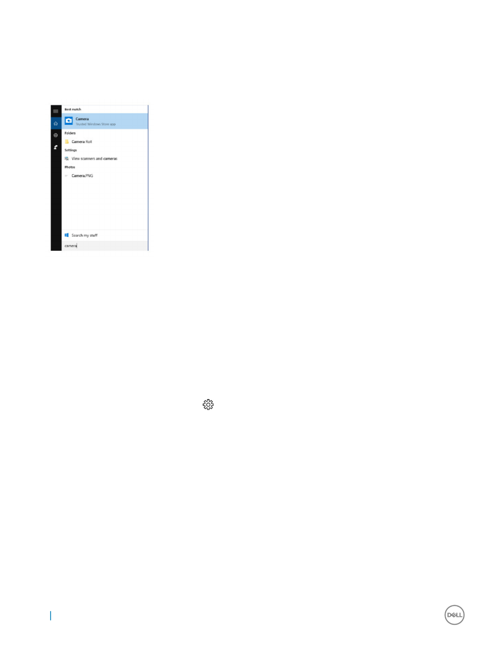
St
St
St
StStarting the camer
arting the camer
arting the camer
arting the camerarting the camera application
a application
a application
a applicationa application
1 On the taskbar, click the search box, and then type Camera.
2 Click .
Camera
Camera
Camera
CameraCamera
Memory f
Memory f
Memory f
Memory fMemory fea
ea
ea
eaeatur
tur
tur
turtures
es
es
eses
In this computer, the memory (RAM) is a part of the system board. This computer supports 2133 MHz DDR4 for Intel 6th and 7th
generation processors.
V
V
V
VVerifying s
erifying s
erifying s
erifying serifying syst
yst
yst
ystystem memory in Windows 10 and Windo
em memory in Windows 10 and Windo
em memory in Windows 10 and Windo
em memory in Windows 10 and Windoem memory in Windows 10 and Windows 7
ws 7
ws 7
ws 7 ws 7
Windows 10
Windows 10
Windows 10
Windows 10Windows 10
1 Click the button and select
Windows
Windows
Windows
WindowsWindows All Set
All Set
All Set
All SetAll Settings
tings
tings
tings tings Syst
Syst
Syst
SystSystem
em
em
emem > .
2 Under Syst
Syst
Syst
SystSystem
em
em
emem About
About
About
AboutAbout, click .
Windows 7
Windows 7
Windows 7
Windows 7Windows 7
1 Click →
Start
Start
Start
StartStart Con
Con
Con
ConControl P
trol P
trol P
trol Ptrol Panel
anel
anel
anelanel System
System
System
SystemSystem →
V
V
V
VVerifying s
erifying s
erifying s
erifying serifying syst
yst
yst
ystystem memory in setup
em memory in setup
em memory in setup
em memory in setupem memory in setup
1 Turn on or restart your computer..
2 Perform one of the following actions after the Dell logo is displayed:
• With keyboard — Tap F2 until the Entering BIOS setup message appears.
• Without keyboard — To enter the Boot section menu, tap F12.
3 On the left pane, select Settings
Settings
Settings
SettingsSettings > >
General
General
General
GeneralGeneral S
S
S
SSystem Inf
ystem Inf
ystem Inf
ystem Infystem Information
ormation
ormation
ormationormation,
The memory information is displayed on the right pane.
82 Technology and components
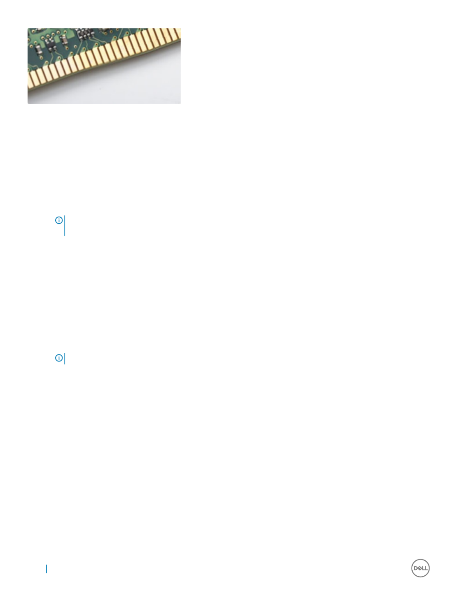
Figur
Figur
Figur
FigurFigure 4. Curved edge
e 4. Curved edge
e 4. Curved edge
e 4. Curved edgee 4. Curved edge
T
T
T
TT
esting memory using ePSA
esting memory using ePSA
esting memory using ePSA
esting memory using ePSAesting memory using ePSA
1 Turn on or restart your computer.
2 Perform one of the following actions after the Dell logo is displayed:
• With keyboard — Press F2.
The PreBoot System Assessment (PSA) starts on your computer.
NOTE:
NOTE:
NOTE:
NOTE: NOTE: If y
If y
If y
If yIf you wait t
ou wait t
ou wait t
ou wait tou wait too long and the opera
oo long and the opera
oo long and the opera
oo long and the operaoo long and the operating syst
ting syst
ting syst
ting systting system logo appears, con
em logo appears, con
em logo appears, con
em logo appears, conem logo appears, continue to w
tinue to w
tinue to w
tinue to wtinue to wait until you see the deskt
ait until you see the deskt
ait until you see the deskt
ait until you see the desktait until you see the desktop. T
op. T
op. T
op. Top. Turn
urn
urn
urn urn o
o
o
oo
the computer and try again.
the computer and try again.
the computer and try again.
the computer and try again.the computer and try again.
Media-car
Media-car
Media-car
Media-carMedia-card r
d r
d r
d rd reader
eader
eader
eadereader
This computer has one SD card slot located on the left side of your computer.
Downloading the media-car
Downloading the media-car
Downloading the media-car
Downloading the media-carDownloading the media-card r
d r
d r
d rd reader driv
eader driv
eader driv
eader driveader driver
er
er
erer
1 Turn on your computer.
2 Go to Dell.
Dell.
Dell.
Dell.Dell.com/
com/
com/
com/com/support
support
support
supportsupport.
3 Click Pr
Pr
Pr
PrProduct Support
oduct Support
oduct Support
oduct Supportoduct Support, enter the Service Tag of your computer and click .
Submit
Submit
Submit
SubmitSubmit
NOTE
NOTE
NOTE
NOTENOTE:
:
:
: : If you do not ha
If you do not ha
If you do not ha
If you do not haIf you do not have the Service T
ve the Service T
ve the Service T
ve the Service Tve the Service T
ag, use the aut
ag, use the aut
ag, use the aut
ag, use the autag, use the auto-det
o-det
o-det
o-deto-detect f
ect f
ect f
ect fect featur
eatur
eatur
eatureature or manually br
e or manually br
e or manually br
e or manually bre or manually browse f
owse f
owse f
owse fowse for your comput
or your comput
or your comput
or your computor your computer model.
er model.
er model.
er model.er model.
4 Click Drivers & do
Drivers & do
Drivers & do
Drivers & doDrivers & downloads
wnloads
wnloads
wnloadswnloads.
5 Click .
Find it myself
Find it myself
Find it myself
Find it myselfFind it myself
6 Scroll down the page and expand .
Chipset
Chipset
Chipset
ChipsetChipset
7 Click to download the media-card reader driver for your computer.
Download
Download
Download
Download Download
8 After the download is complete, navigate to the folder where you saved the media-card reader driver le.
9 Double-click the card-reader driver icon and follow the instructions on the screen.le
Realt
Realt
Realt
RealtRealtek HD audio drivers
ek HD audio drivers
ek HD audio drivers
ek HD audio driversek HD audio drivers
Verify if the Realtek audio drivers are already installed in the computer.
84 Technology and components
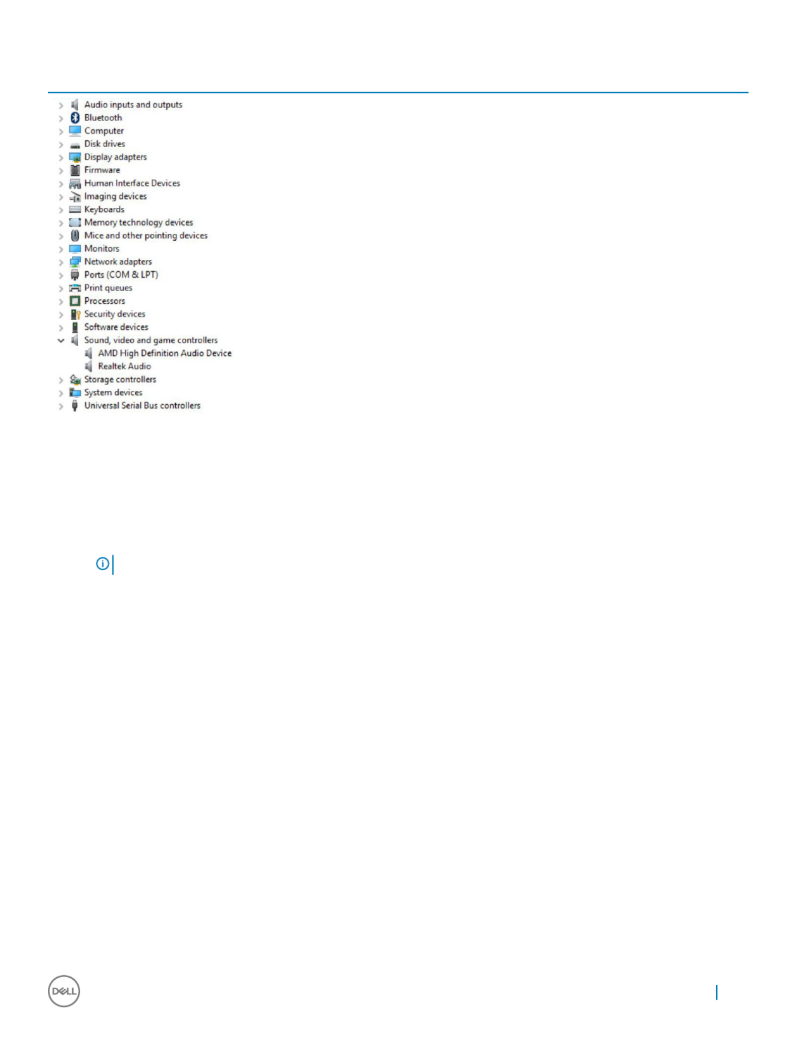
T
T
T
TT
able 5
able 5
able 5
able 5able 5. Realt
. Realt
. Realt
. Realt. Realtek HD audio drivers
ek HD audio drivers
ek HD audio drivers
ek HD audio driversek HD audio drivers
Downloading the audio driv
Downloading the audio driv
Downloading the audio driv
Downloading the audio drivDownloading the audio driver
er
er
erer
1 Turn on your computer.
2 Go to dell.
dell.
dell.
dell.dell.com/
com/
com/
com/com/support
support
support
supportsupport.
3 Click Pr
Pr
Pr
PrProduct support
oduct support
oduct support
oduct supportoduct support, enter the Service Tag of your computer, and then click .
Submit
Submit
Submit
SubmitSubmit
NOTE
NOTE
NOTE
NOTENOTE:
:
:
: : If you do not ha
If you do not ha
If you do not ha
If you do not haIf you do not have the Service T
ve the Service T
ve the Service T
ve the Service Tve the Service T
ag, use the aut
ag, use the aut
ag, use the aut
ag, use the autag, use the auto-det
o-det
o-det
o-deto-detect f
ect f
ect f
ect fect featur
eatur
eatur
eatureature or manually br
e or manually br
e or manually br
e or manually bre or manually bro
o
o
oowse for y
wse for y
wse for y
wse for ywse for your computer model.
our computer model.
our computer model.
our computer model.our computer model.
4 Click Drivers & do
Drivers & do
Drivers & do
Drivers & doDrivers & downloads
wnloads
wnloads
wnloadswnloads Find it myself
Find it myself
Find it myself
Find it myselfFind it myself > .
5 Scroll down the page and expand A
A
A
AAudio
udio
udio
udioudio.
6 Click to download the audio driver.
Download
Download
Download
DownloadDownload
7 Save the and after the download is complete, navigate to the folder where you saved the audio driver le, le.
8 Double-click the audio driver icon and follow the instructions on the screen to install the driver.le
Oper
Oper
Oper
OperOpera
a
a
aating S
ting S
ting S
ting Sting Syst
yst
yst
ystystem
em
em
emem
This computer is shipped with the Windows 10 factory installation.
Service tag loca
Service tag loca
Service tag loca
Service tag locaService tag location
tion
tion
tiontion
The service tag is a unique alphanumeric that allows Dell service technicians to identify the hardware components in your identier
computer and access warranty information.
Technology and components 85

86 Technology and components

Syst
Syst
Syst
SystSystem setup
em setup
em setup
em setupem setup
System Setup enables you to manage your desktop hardware and specify BIOS level options. From the System Setup, you can:
• Change the NVRAM settings after you add or remove hardware
• View the system hardware conguration
• Enable or disable integrated devices
• Set performance and power management thresholds
• Manage your computer security
Topics:
• BIOS Overview
• System setup options
BIOS Overvie
BIOS Overvie
BIOS Overvie
BIOS OvervieBIOS Overview
w
w
ww
Boot menu
Boot menu
Boot menu
Boot menuBoot menu
Press <F12> when the Dell™ logo appears to initiate a one-time boot menu with a list of the valid boot devices for the system. Diagnostics
and BIOS Setup options are also included in this menu. The devices listed on the boot menu depend on the bootable devices in the system.
This menu is useful when you are attempting to boot to a particular device or to bring up the diagnostics for the system. Using the boot
menu does not make any changes to the boot order stored in the BIOS.
The options are:
• Legacy Boot:
• Internal HDD
• Onboard NIC
• UEFI Boot:
• Windows Boot Manager
• Other Options:
• BIOS Setup
• BIOS Flash Update
• Diagnostics
• Change Boot Mode Settings
Na
Na
Na
NaNaviga
viga
viga
vigavigation K
tion K
tion K
tion Ktion Keys
eys
eys
eyseys
The following table displays the system setup navigation keys.
NOTE
NOTE
NOTE
NOTENOTE:
:
:
: : For most of the s
For most of the s
For most of the s
For most of the sFor most of the system se
ystem se
ystem se
ystem seystem setup options, changes tha
tup options, changes tha
tup options, changes tha
tup options, changes thatup options, changes that you make ar
t you make ar
t you make ar
t you make art you make are r
e r
e r
e re recor
ecor
ecor
ecorecorded but do no
ded but do no
ded but do no
ded but do noded but do not take
t take
t take
t take t take e
e
e
eeect
ect
ect
ectect until y
until y
until y
until y until you r
ou r
ou r
ou rou re-start the
e-start the
e-start the
e-start the e-start the
syst
syst
syst
systsystem.
em.
em.
em.em.
4
4
4
44
System setup 87

T
T
T
TT
able 7
able 7
able 7
able 7able 7
. General
. General
. General
. General. General
Option
Option
Option
OptionOption Description
Description
Description
DescriptionDescription
System Information Displays the following information:
• System Information: Displays BIOS V
BIOS V
BIOS V
BIOS VBIOS Ver
er
er
erersion, Service T
sion, Service T
sion, Service T
sion, Service Tsion, Service T
ag, Asset T
ag, Asset T
ag, Asset T
ag, Asset Tag, Asset T
ag, Ownership T
ag, Ownership T
ag, Ownership T
ag, Ownership Tag, Ownership T
ag, Owner
ag, Owner
ag, Owner
ag, Ownerag, Ownership
ship
ship
ship ship
Dat
Dat
Dat
DatDate, Manuf
e, Manuf
e, Manuf
e, Manufe, Manufactur
actur
actur
acturacture Dat
e Dat
e Dat
e Date Date,
e,
e,
e,e, Expr
Expr
Expr
ExprExpress Service Code
ess Service Code
ess Service Code
ess Service Codeess Service Code and the .
• Memory Information: Displays Memory Installed, Memory A
Memory Installed, Memory A
Memory Installed, Memory A
Memory Installed, Memory AMemory Installed, Memory Available
vailable
vailable
vailablevailable, Memory Speed, Memory
, Memory Speed, Memory
, Memory Speed, Memory
, Memory Speed, Memory , Memory Speed, Memory
Channel Mode, Memory T
Channel Mode, Memory T
Channel Mode, Memory T
Channel Mode, Memory TChannel Mode, Memory T
echnology
echnology
echnology
echnologyechnology, DIMM 1 Size
, DIMM 1 Size
, DIMM 1 Size
, DIMM 1 Size, DIMM 1 Size DIMM 2 Siz
DIMM 2 Siz
DIMM 2 Siz
DIMM 2 SizDIMM 2 Size
e
e
ee DIMM 3 Siz
DIMM 3 Siz
DIMM 3 Siz
DIMM 3 SizDIMM 3 Size
e
e
ee DIMM 4
DIMM 4
DIMM 4
DIMM 4 DIMM 4 , , , and
Size
Size
Size
SizeSize.
• PCI Information: Displays SLOT1 and SLOT2_M.2.
• Processor Information: Displays Pr
Pr
Pr
PrProcessor T
ocessor T
ocessor T
ocessor Tocessor T
ype, Cor
ype, Cor
ype, Cor
ype, Corype, Core Count, Pr
e Count, Pr
e Count, Pr
e Count, Pre Count, Processor ID
ocessor ID
ocessor ID
ocessor IDocessor ID, Curr
, Curr
, Curr
, Curr, Current Clock
ent Clock
ent Clock
ent Clock ent Clock
Speed, Minimum Clock Speed, Maximum Clock Speed, Pr
Speed, Minimum Clock Speed, Maximum Clock Speed, Pr
Speed, Minimum Clock Speed, Maximum Clock Speed, Pr
Speed, Minimum Clock Speed, Maximum Clock Speed, PrSpeed, Minimum Clock Speed, Maximum Clock Speed, Processor L2 Cache, Processor L
ocessor L2 Cache, Processor L
ocessor L2 Cache, Processor L
ocessor L2 Cache, Processor Locessor L2 Cache, Processor L3
3
3
3 3
Cache, HT Capable,
Cache, HT Capable,
Cache, HT Capable,
Cache, HT Capable,Cache, HT Capable, 64-Bit T
64-Bit T
64-Bit T
64-Bit T64-Bit T
echnology
echnology
echnology
echnologyechnology.
.
.
.. and
• Device Information: Displays SA
SA
SA
SASAT
T
T
TTA-0
A-0
A-0
A-0A-0, SA
, SA
, SA
, SA, SAT
T
T
TTA-
A-
A-
A-A-1, SA
1, SA
1, SA
1, SA1, SAT
T
T
TTA-
A-
A-
A-A-4, M.2 PCIe SSD-0
4, M.2 PCIe SSD-0
4, M.2 PCIe SSD-0
4, M.2 PCIe SSD-04, M.2 PCIe SSD-0, LOM MAC A
, LOM MAC A
, LOM MAC A
, LOM MAC A, LOM MAC Addr
ddr
ddr
ddrddress,
ess,
ess,
ess, ess,
Video Contr
Video Contr
Video Contr
Video ContrVideo Controller
oller
oller
olleroller, dGPU video contr
, dGPU video contr
, dGPU video contr
, dGPU video contr, dGPU video controller
oller
oller
olleroller, Video BIOS version, Video memory
, Video BIOS version, Video memory
, Video BIOS version, Video memory
, Video BIOS version, Video memory, Video BIOS version, Video memory
, panel type,
, panel type,
, panel type,
, panel type, , panel type,
Native r
Native r
Native r
Native rNative resolution, Wi-Fi Device, Bluet
esolution, Wi-Fi Device, Bluet
esolution, Wi-Fi Device, Bluet
esolution, Wi-Fi Device, Bluetesolution, Wi-Fi Device, Bluetooth Device, and Audio Con
ooth Device, and Audio Con
ooth Device, and Audio Con
ooth Device, and Audio Conooth Device, and Audio Contr
tr
tr
trtroller
oller
oller
olleroller.
.
.
. . .
Boot Sequence Allows you to specify the order in which the computer attempts to an operating system from the nd
devices in this list.specied
• Legacy
• (default)
UEFI
UEFI
UEFI
UEFIUEFI
Advanced Boot Options Allows you to select the Enable Legacy Option ROMs option, when in UEFI boot mode.
Allows you to select the Enable Attempt Legacy Boot option.
Date/Time Allows you to set the date and time settings. Changes to the system date and time take eect
immediately.
T
T
T
TT
able 8
able 8
able 8
able 8able 8. Syst
. Syst
. Syst
. Syst. System
em
em
em em Congur
Congur
Congur
CongurConguration
ation
ation
ationation
Option
Option
Option
OptionOption Description
Description
Description
DescriptionDescription
Integrated NIC Allows you to control the on-board LAN controller. The option ‘Enable UEFI Network Stack’ is not
selected by default. The options are:
• Disabled
• Enabled
•Enabled w
Enabled w
Enabled w
Enabled wEnabled w/PXE
/PXE
/PXE
/PXE/PXE (default)
NOTE:
NOTE:
NOTE:
NOTE: NOTE: Depending on the comput
Depending on the comput
Depending on the comput
Depending on the computDepending on the computer and its installed devices, the it
er and its installed devices, the it
er and its installed devices, the it
er and its installed devices, the iter and its installed devices, the items listed in this section
ems listed in this section
ems listed in this section
ems listed in this section ems listed in this section
may or ma
may or ma
may or ma
may or mamay or may not appear
y not appear
y not appear
y not appeary not appear.
.
.
..
SATA Operation Allows you to the operating mode of the integrated hard drive controller.congure
• Disabled = The SATA controllers are hidden
• = SATA is to support RAID mode (selected by default)
RAID ON
RAID ON
RAID ON
RAID ONRAID ON congured
• AHCI= SATA is for AHCI modecongured
Drives Allows you to enable or disable the various drives on-board:
• SATA-0
• SATA-1
• SATA-4
• M.2 PCIE SSD-0
Smart Reporting This controls whether hard drive errors for integrated drives are reported during system startup. eld
The is disabled by default.
Enable Smart Reporting option
Enable Smart Reporting option
Enable Smart Reporting option
Enable Smart Reporting optionEnable Smart Reporting option
USB Conguration Allows you to enable or disable the integrated USB controller for:
System setup 89

Option
Option
Option
OptionOption Description
Description
Description
DescriptionDescription
•Enable Boot Support
Enable Boot Support
Enable Boot Support
Enable Boot SupportEnable Boot Support
•Enable Side USB Port
Enable Side USB Port
Enable Side USB Port
Enable Side USB PortEnable Side USB Ports
s
s
s s
•Enable Rear USB P
Enable Rear USB P
Enable Rear USB P
Enable Rear USB PEnable Rear USB Ports
orts
orts
ortsorts
All the options are selected by default.
Rear USB Conguration Allows you to enable or disable the back USB ports. All the ports are enabled by default.
Side USB Conguration Allows you to enable or disable the side USB ports
USB PowerShare This option allows you to charge the external devices, such as mobile phones, music player. This
option is disabled by default.
Thunderbolt This option is enabled by default. The options that you see are:
• No Security
• User Congurations (default)
• Secure Connect
• Display Port Only
Audio Allows you to enable or disable the integrated audio controller. The option is selected by
Enable Audio
Enable Audio
Enable Audio
Enable AudioEnable Audio
default.
•Enable Micr
Enable Micr
Enable Micr
Enable MicrEnable Microphone
ophone
ophone
ophoneophone
•Enable Int
Enable Int
Enable Int
Enable IntEnable Internal Speaker
ernal Speaker
ernal Speaker
ernal Speakerernal Speaker
Both the options are selected by default.
Touchscreen This controls whether the touchscreen is enabled or disabled.eld
Miscellaneous Allows you to enable or disable the various on-board devices.
• (default)
Enable camera
Enable camera
Enable camera
Enable cameraEnable camera
•Secur
Secur
Secur
SecurSecure Digital (
e Digital (
e Digital (
e Digital (e Digital (SD
SD
SD
SDSD) Car
) Car
) Car
) Car) Card
d
d
dd (default)
• Disable Media Card
T
T
T
TTable 9
able 9
able 9
able 9able 9. Video
. Video
. Video
. Video. Video
Option
Option
Option
OptionOption Description
Description
Description
DescriptionDescription
Switchable Graphics This option sets the operating mode of the system's graphics hardware.
•Disabled
Disabled
Disabled
DisabledDisabled
• Enabled
T
T
T
TTable 10
able 10
able 10
able 10able 10. Security
. Security
. Security
. Security. Security
Option
Option
Option
OptionOption Description
Description
Description
DescriptionDescription
Admin Password Allows you to set, change, and delete the admin password.
System Password Allows you to set, change, and delete the system password.
Internal HDD-0 Password Allows you to set, change, and delete the computer’s internal HDD.
Strong Password This option lets you enable or disable strong passwords for the system. Enable Strong Password
option is not selected by default.
Password Allows you to control the minimum and maximum number of characters allowed for a administrative Conguration
password and the system password. The range of characters is between 4 and 32.
90 System setup

Option
Option
Option
OptionOption Description
Description
Description
DescriptionDescription
Password Bypass This option lets you bypass the System (Boot) Password and the internal HDD password prompts
during a system restart.
• Disabled — Always prompt for the system and internal HDD password when they are set. This
option is selected by default.
• Reboot Bypass — Bypass the password prompts on Restarts (warm boots).
NOTE:
NOTE:
NOTE:
NOTE: NOTE: The s
The s
The s
The sThe system will alw
ystem will alw
ystem will alw
ystem will alwystem will always pr
ays pr
ays pr
ays prays prompt for the s
ompt for the s
ompt for the s
ompt for the sompt for the system and in
ystem and in
ystem and in
ystem and inystem and internal HDD pass
ternal HDD pass
ternal HDD pass
ternal HDD passternal HDD passwor
wor
wor
worwords when
ds when
ds when
ds when ds when
power
power
power
powerpowered on from the
ed on from the
ed on from the
ed on from the ed on from the o
o
o
oo
stat
stat
stat
stat state (a cold boot
e (a cold boot
e (a cold boot
e (a cold boote (a cold boot). Also, the system will alw
). Also, the system will alw
). Also, the system will alw
). Also, the system will alw). Also, the system will always pr
ays pr
ays pr
ays prays prompt for
ompt for
ompt for
ompt for ompt for
passwor
passwor
passwor
passworpasswords on any module bay HDDs tha
ds on any module bay HDDs tha
ds on any module bay HDDs tha
ds on any module bay HDDs thads on any module bay HDDs that may be pr
t may be pr
t may be pr
t may be prt may be present.
esent.
esent.
esent.esent.
Password Change This option lets you determine whether changes to the System and Hard Disk passwords are
permitted when an administrator password is set.
Allow Non-A
Allow Non-A
Allow Non-A
Allow Non-AAllow Non-Admin Pass
dmin Pass
dmin Pass
dmin Passdmin Passwor
wor
wor
worword Changes
d Changes
d Changes
d Changes d Changes - This option is enabled by default.
UEFI Capsule Firmware Updates This option controls whether this system allows BIOS updates via UEFI capsule update packages. The
option "Enable UEFI Capsule Firmware Updates" is selected by default. Disabling this option will block
BIOS updates from services such as Microsoft Windows Update and Linux Vendor Firmware Service
(LVFS)
TPM 2.0 Security Allows you to control whether the Trusted Platform Module (TPM) is visible to the operating system.
• TPM On (default)
• Clear (disabled)
• PPI Bypass for Enable Commands
• PPI Bypass for Disable Commands
• Disabled
• Enabled (default)
Computrace This lets you Activate or Disable the BIOS module interface of the optional Computrace Service eld
from Absolute Software. Enables or disables the optional Computrace service designed for asset
management.
•Deactiva
Deactiva
Deactiva
DeactivaDeactivate
te
te
te te - This option is selected by default.
• Disable
• Activate
Chassis Intrusion Allows you to control the chassis intrusion feature. You can set this option to:
• Enabled
• (default)
Disabled
Disabled
Disabled
DisabledDisabled
• On-Silent
CPU XD Support Allows you to enable or disable the Execute Disable mode of the processor. This option is enabled by
default.
OROM Keyboard Access This option determines whether users are able to enter Option ROM Conguration screens via
hotkeys during boot. Specically, these settings are capable of preventing access to Intel RAID (CTRL
+I) or Intel Management Engine BIOS Extension (CTRL+P/F12).
• Enable (selected by default)— User may enter OROM conguration screens via the hotkey.
• One-Time Enable — User may enter OROM conguration screens via the hotkeys on next boot
only. After next boot, the setting will revert to disabled.
• Disable — User may not enter OROM conguration screens via the hotkey.
Admin Setup Lockout Allows you to enable or disable the option to enter Setup when an Administrative password is set.
This option is not set by default.
System setup 91

T
T
T
TT
able 11. Secur
able 11. Secur
able 11. Secur
able 11. Securable 11. Secure Boot
e Boot
e Boot
e Boote Boot
Option
Option
Option
OptionOption Description
Description
Description
DescriptionDescription
Secure Boot Enable Allows you to enable or disable Secure Boot feature
• Disabled
• (default)
Enable
Enable
Enable
EnableEnable
Expert key Management Allows you to manipulate the security key databases only if the system is in Custom Mode. The
Enable Custom Mode
Enable Custom Mode
Enable Custom Mode
Enable Custom ModeEnable Custom Mode option is disabled by default. The options are:
• PK (default)
• KEK
• db
• dbx
If you enable the Cust
Cust
Cust
CustCustom Mode
om Mode
om Mode
om Modeom Mode, the relevant options for appear. The
PK, KEK
PK, KEK
PK, KEK
PK, KEK PK, KEK, db, and dbx
, db, and dbx
, db, and dbx
, db, and dbx, db, and dbx
options are:
•Sav
Sav
Sav
SavSave to File
e to File
e to File
e to Filee to File- Saves the key to a user-selected le
•Replace fr
Replace fr
Replace fr
Replace frReplace from File
om File
om File
om Fileom File- Replaces the current key with a key from a user-selected le
•Append fr
Append fr
Append fr
Append frAppend from File
om File
om File
om Fileom File- Adds a key to the current database from a user-selected le
•Delet
Delet
Delet
DeletDelete
e
e
ee- Deletes the selected key
•Reset All K
Reset All K
Reset All K
Reset All KReset All Ke
e
e
eeys
ys
ys
ysys- Resets to default setting
•Delet
Delet
Delet
DeletDelete All K
e All K
e All K
e All Ke All Key
ey
ey
eyeys- Deletes all the keys
NOTE:
NOTE:
NOTE:
NOTE: NOTE: If y
If y
If y
If yIf you disable the Custom Mode
ou disable the Custom Mode
ou disable the Custom Mode
ou disable the Custom Modeou disable the Custom Mode, all the changes made will be erased and the
, all the changes made will be erased and the
, all the changes made will be erased and the
, all the changes made will be erased and the , all the changes made will be erased and the
keys will r
keys will r
keys will r
keys will rkeys will rest
est
est
estestor
or
or
orore t
e t
e t
e te to def
o def
o def
o defo default settings
ault settings
ault settings
ault settingsault settings.
.
.
..
T
T
T
TT
able 12. Int
able 12. Int
able 12. Int
able 12. Intable 12. Intel Softwar
el Softwar
el Softwar
el Softwarel Software Guar
e Guar
e Guar
e Guare Guard Ext
d Ext
d Ext
d Extd Extensions
ensions
ensions
ensionsensions
Option
Option
Option
OptionOption Description
Description
Description
DescriptionDescription
Intel SGX Enable Allows you to enable or disable the Intel Software Guard Extensions to provide a secured
environment for running code/storing sensitive information in the context of the main operating
system.
• (default)
Disabled
Disabled
Disabled
DisabledDisabled
• Enabled
Enclave Memory Size Allows you to set the Intel SGX Enclave Reserve Memory Size.
• 32 MB
• 64 MB (Disabled by default)
• 128 MB (Disabled by default)
T
T
T
TT
able 13
able 13
able 13
able 13able 13. Perf
. Perf
. Perf
. Perf. Performance
ormance
ormance
ormanceormance
Option Description
Multi Core Support This whether the process will have one or all cores enabled. This option is enabled by eld species
default.
options:
• (default)
All
All
All
AllAll
• 1
• 2
92 System setup

• 3
Intel SpeedStep Allows you to enable or disable the Intel SpeedStep mode of the processor. This option is enabled
by default.
C States Control Allows you to enable or disable additional processor sleep states. This option is enabled by default.
Limited CPUID Value Allows you to limit the maximum value of the processor standard CPUID function. This options is
disable by default.
Intel TurboBoost Allows you to enable or disable the Intel TurboBoost mode of the processor. This option is enabled
by default.
HyperThread control • Disabled
• (default)
Enabled
Enabled
Enabled
EnabledEnabled
T
T
T
TTable 14. P
able 14. P
able 14. P
able 14. Pable 14. Pow
ow
ow
owower Management
er Management
er Management
er Managementer Management
Option
Option
Option
OptionOption Description
Description
Description
DescriptionDescription
AC Recovery Determines how the system responds when AC power is re-applied after a power loss. You can set
the AC Recovery to:
• Power O
• Power On
• Last Power State
This option is Power by default.O
Auto On Time Sets time to automatically turn on the computer. Time is kept in standard 12-hour format
(hour:minutes:seconds). Change the startup time by typing the values in the time and AM/PM elds.
NOTE:
NOTE:
NOTE:
NOTE: NOTE: This f
This f
This f
This fThis featur
eatur
eatur
eatureature does no
e does no
e does no
e does noe does not work if you turn
t work if you turn
t work if you turn
t work if you turn t work if you turn o
o
o
oo
your comput
your comput
your comput
your comput your computer using the swit
er using the swit
er using the swit
er using the switer using the switch on a
ch on a
ch on a
ch on a ch on a
power strip or sur
power strip or sur
power strip or sur
power strip or surpower strip or surge pr
ge pr
ge pr
ge prge pro
o
o
ootec
tec
tec
tectector or if A
tor or if A
tor or if A
tor or if Ator or if Auto P
uto P
uto P
uto Puto Pow
ow
ow
owower is set t
er is set t
er is set t
er is set ter is set to disabled.
o disabled.
o disabled.
o disabled.o disabled.
Deep Sleep Control Allows you to the controls when Deep Sleep is enabled.dene
• Disabled
• Enabled in S5 only
• Enabled in S4 and S5
This option is by default.
Enabled in S4 and S5
Enabled in S4 and S5
Enabled in S4 and S5
Enabled in S4 and S5Enabled in S4 and S5
Fan Control Override Allows you to determine the speed of the system fan. When this option is enabled, the system fan
runs at the maximum speed. This option is disabled by default.
USB Wake Support Allows you to enable the USB devices to wake the computer from standby mode. The option Enable
Enable
Enable
Enable Enable
USB W
USB W
USB W
USB WUSB Wak
ak
ak
akake Support
e Support
e Support
e Supporte Support is selected by default
Wake on WLAN This option allows the computer to power up from the o state when triggered by a special LAN
signal. This feature only works when the computer is connected to AC power supply.
• - Does not allows the system to power on by special LAN signals when it receives a
Disabled
Disabled
Disabled
DisabledDisabled
wake-up signal from the LAN or wireless LAN.
• or - Allows the system to be powered on by special LAN or wireless LAN signals.
LAN
LAN
LAN
LANLAN WL
WL
WL
WLWLAN
AN
AN
ANAN
• - Allows the system to be powered on by special LAN signals.
LAN Only
LAN Only
LAN Only
LAN OnlyLAN Only
• - A wakeup packet sent to the system in either the S4 or S5 state, that will
LAN with PXE Boot
LAN with PXE Boot
LAN with PXE Boot
LAN with PXE BootLAN with PXE Boot
cause the system to wake-up and immediately boot to PXE.
• - Allows the system to be powered on by special WLAN signals.
WLAN Only
WLAN Only
WLAN Only
WLAN OnlyWLAN Only
This option is Disabled by default.
Block Sleep Allows you to block entering to sleep (S3 state) in OS environment. This option is disabled by default.
System setup 93

Option
Option
Option
OptionOption Description
Description
Description
DescriptionDescription
Intel Ready Mode Allows you to enable the capability of Intel Ready Mode Technology. This option is disabled by default.
T
T
T
TT
able 15
able 15
able 15
able 15able 15. POST Beha
. POST Beha
. POST Beha
. POST Beha. POST Behavior
vior
vior
viorvior
Option
Option
Option
OptionOption Description
Description
Description
DescriptionDescription
Numlock LED Allows you to enable or disable the Numlock feature when your computer starts. This option is
enabled by default.
Keyboard Errors Allows you to enable or disable the keyboard error reporting when the computer starts. This option is
selected by default.
Fast Boot This option can speed up the boot process by bypassing some compatibility steps:
• Minimal — The system boots quickly, unless the BIOS has been updated, memory changed, or
the previous POST did not complete.
•Thor
Thor
Thor
ThorThorough
ough
ough
oughough — The system does not skip any steps in the boot process.
• Auto — This allows the operating system to control this setting (this works only when the
operating system supports Simple Boot Flag).
This option is set to Thr
Thr
Thr
ThrThrough
ough
ough
oughough by default.
MEBx HotKey This option is selected by default
T
T
T
TT
able 16
able 16
able 16
able 16able 16. Virtualization Support
. Virtualization Support
. Virtualization Support
. Virtualization Support. Virtualization Support
Option
Option
Option
OptionOption Description
Description
Description
DescriptionDescription
Virtualization This option whether a Virtual Machine Monitor (VMM) can utilize the additional hardware species
capabilities provided by Intel® Virtualization Technology. Enable Int
Enable Int
Enable Int
Enable IntEnable Intel Virtualization T
el Virtualization T
el Virtualization T
el Virtualization Tel Virtualization T
echnology
echnology
echnology
echnologyechnology -
This option is selected by default.
VT for Direct I/O Enables or disables the Virtual Machine Monitor (VMM) from utilizing the additional hardware
capabilities provided by Intel® Virtualization technology for direct I/O. Enable VT f
Enable VT f
Enable VT f
Enable VT fEnable VT for Dir
or Dir
or Dir
or Diror Direct I/
ect I/
ect I/
ect I/ect I/O
O
O
OO -
This option is selected by default.
Trusted Execution The option Trusted Execution is not selected by default
T
T
T
TT
able 17
able 17
able 17
able 17able 17
. Wireless
. Wireless
. Wireless
. Wireless. Wireless
Wireless Device Enable Allows you to enable the following options.
• WLAN/WGig
• Bluetooth
T
T
T
TT
able 18
able 18
able 18
able 18able 18. Maint
. Maint
. Maint
. Maint. Maintenance
enance
enance
enanceenance
Option
Option
Option
OptionOption Description
Description
Description
DescriptionDescription
Service Tag Displays the Service Tag of your computer.
Asset Tag Allows you to create a system asset tag if an asset tag is not already set. This option is set by default.
SERR Messages Controls the SERR message mechanism. This option is set by default. Some graphics cards require
that the SERR message mechanism be disabled.
BIOS Downgrade Allows you to control of the system ashing rmware to the previous versions. This option is enabled
by default.
NOTE:
NOTE:
NOTE:
NOTE: NOTE: If this op
If this op
If this op
If this opIf this option is not select
tion is not select
tion is not select
tion is not selecttion is not selected, the
ed, the
ed, the
ed, the ed, the of the s
of the s
of the s
of the s of the system
ystem
ystem
ystem ystem
ashing
ashing
ashing
ashingashing rm
rm
rm
rmrmwar
war
war
warware
e
e
ee t
t
t
t to the pr
o the pr
o the pr
o the pro the previous
evious
evious
evious evious
versions is block
versions is block
versions is block
versions is blockversions is blocked.
ed.
ed.
ed.ed.
94 System setup

Option
Option
Option
OptionOption Description
Description
Description
DescriptionDescription
Data Wipe Allows you to securely erase the data from all the available internal storages, such as HDD, SSD,
mSATA, and eMMC. The option Wipe on Next Boot is disabled by default.
BIOS recovery Allows you to recover the corrupted BIOS conditions from the recovery on the primary hard les
drive. The option BIOS Recovery fr
BIOS Recovery fr
BIOS Recovery fr
BIOS Recovery frBIOS Recovery from Hard Drive
om Hard Drive
om Hard Drive
om Hard Driveom Hard Drive is selected by default
T
T
T
TT
able 19
able 19
able 19
able 19able 19. System L
. System L
. System L
. System L. System Logs
ogs
ogs
ogsogs
Option
Option
Option
OptionOption Description
Description
Description
DescriptionDescription
BIOS Events Displays the system event log and allows you to:
• Clear Log
• Mark all Entries
T
T
T
TT
able 20
able 20
able 20
able 20able 20. SupportAsssist System Resolution
. SupportAsssist System Resolution
. SupportAsssist System Resolution
. SupportAsssist System Resolution. SupportAsssist System Resolution
Option
Option
Option
OptionOption Description
Description
Description
DescriptionDescription
Auto OS Recovery Threshold Options:
• o
• 1
• (default)
2
2
2
22
• 3
System setup 95

Softw
Softw
Softw
SoftwSoftwar
ar
ar
arare
e
e
ee
Oper
Oper
Oper
OperOperating s
ating s
ating s
ating sating syst
yst
yst
ystystem
em
em
em em congur
congur
congur
congurcongura
a
a
aations
tions
tions
tionstions
This topic lists the operating system (OS) supported on Precision 5720 AIO systems.
T
T
T
TT
able 21. Opera
able 21. Opera
able 21. Opera
able 21. Operaable 21. Operating systems
ting systems
ting systems
ting systemsting systems
Windows 10 • Factory installed Windows 10 Pro – 64 bit
• Windows® 10 Pro (64-bit) with downgrade rights to Windows™
7 Professional (64-bit) – 6th generation processor
• Factory installed Windows 10 Home – 64 bit
Other Ubuntu 16.04, NeoKylin v6.0, Red Hat Enterprise Linux 7.3
Downloading gr
Downloading gr
Downloading gr
Downloading grDownloading graphic driv
aphic driv
aphic driv
aphic drivaphic drivers
ers
ers
ersers
1 Turn on the computer.
2 Go to Dell.com/
Dell.com/
Dell.com/
Dell.com/Dell.com/support
support
support
supportsupport.
3 Click , enter the Service Tag of your computer, and then click .
Product Support
Product Support
Product Support
Product SupportProduct Support Submit
Submit
Submit
SubmitSubmit
NOTE
NOTE
NOTE
NOTENOTE:
:
:
: : If you do not ha
If you do not ha
If you do not ha
If you do not haIf you do not have the Service T
ve the Service T
ve the Service T
ve the Service Tve the Service T
ag, use the auto det
ag, use the auto det
ag, use the auto det
ag, use the auto detag, use the auto detect fea
ect fea
ect fea
ect feaect feature or manually br
ture or manually br
ture or manually br
ture or manually brture or manually browse for your comput
owse for your comput
owse for your comput
owse for your computowse for your computer model.
er model.
er model.
er model.er model.
4 Click .
Drivers and Downloads
Drivers and Downloads
Drivers and Downloads
Drivers and DownloadsDrivers and Downloads
5 Click tab.
Find it myself
Find it myself
Find it myself
Find it myselfFind it myself
6 Select the operating system installed on your computer.
7 Scroll down the page and select the graphic driver to install.
8 Click to download the graphic driver for your computer.
Download File
Download File
Download File
Download FileDownload File
9 After the download is complete, navigate to the folder where you saved the graphic driver le.
10 Double-click the graphic driver icon and follow the instructions on the screen.le
Int
Int
Int
IntIntel Virtual But
el Virtual But
el Virtual But
el Virtual Butel Virtual Butt
t
t
tton driver
on driver
on driver
on driveron driver
In the Device Manager, check if the Intel Virtual Button driver is installed. Install the driver updates from Dell.com/
Dell.com/
Dell.com/
Dell.com/Dell.com/support
support
support
supportsupport.
5
5
5
55
96 Software
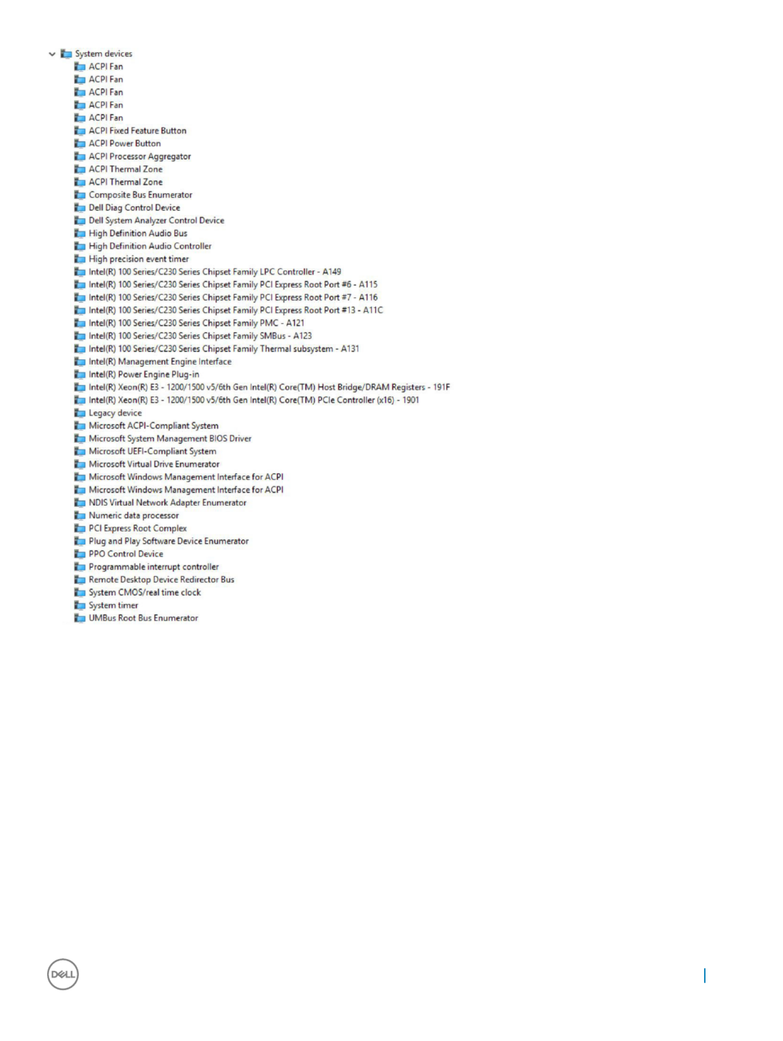
Software 97
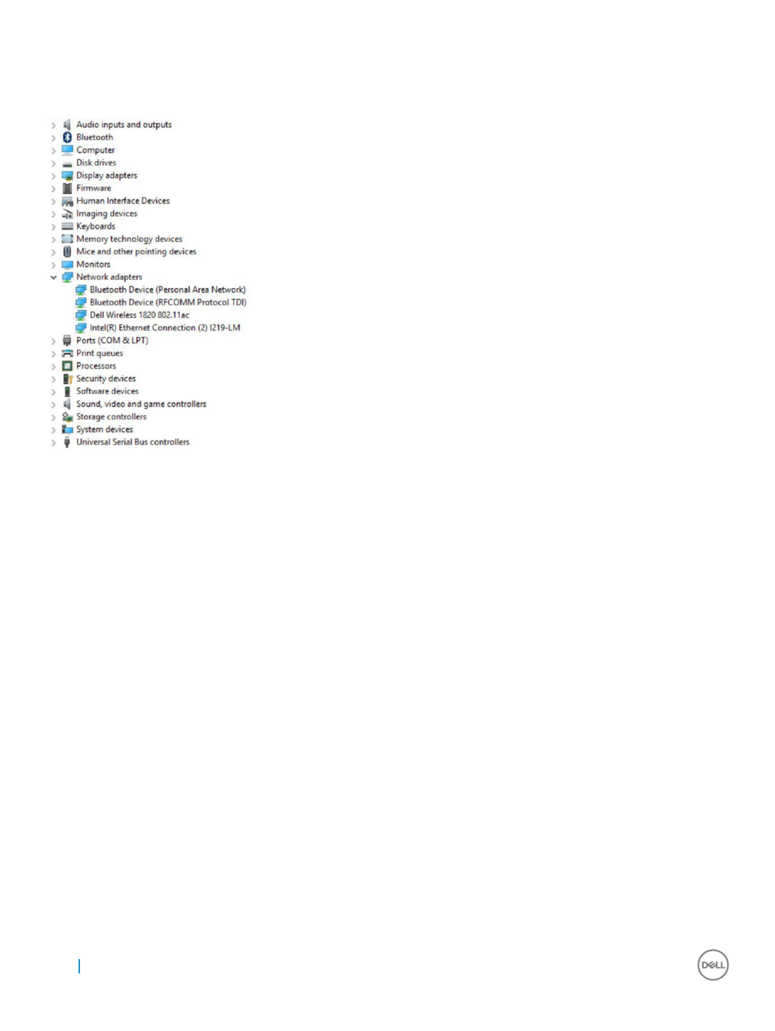
Int
Int
Int
IntIntel Wi-Fi and Bluet
el Wi-Fi and Bluet
el Wi-Fi and Bluet
el Wi-Fi and Bluetel Wi-Fi and Bluetooth driv
ooth driv
ooth driv
ooth drivooth drivers
ers
ers
ersers
In the Device Manager, check if the network card driver is installed. Install the driver updates from dell.com/
dell.com/
dell.com/
dell.com/dell.com/support
support
support
supportsupport.
In the Device Manager, check if the Bluetooth driver is installed. Install the driver updates from
dell.com/
dell.com/
dell.com/
dell.com/dell.com/support
support
support
supportsupport.
Int
Int
Int
IntIntel T
el T
el T
el Tel Trust
rust
rust
rustrusted Execution Engine Int
ed Execution Engine Int
ed Execution Engine Int
ed Execution Engine Inted Execution Engine Interf
erf
erf
erferface
ace
ace
aceace
In the Device Manager, check if the Intel Trusted Execution Engine Interface driver is installed. Install the driver updates from Dell.com/
Dell.com/
Dell.com/
Dell.com/Dell.com/
support
support
support
supportsupport.
98 Software

Int
Int
Int
IntIntel Serial IO Driver
el Serial IO Driver
el Serial IO Driver
el Serial IO Driverel Serial IO Driver
In the Device Manager, check if the Intel Serial IO Driver is installed. Install the driver updates from dell.com/
dell.com/
dell.com/
dell.com/dell.com/support
support
support
supportsupport.
Software 99

100 Software
Produktspecifikationer
| Varumärke: | Dell |
| Kategori: | Skrivbord |
| Modell: | Precision 5720 |
Behöver du hjälp?
Om du behöver hjälp med Dell Precision 5720 ställ en fråga nedan och andra användare kommer att svara dig
Skrivbord Dell Manualer

26 Februari 2025
16 Februari 2025
27 Oktober 2024
17 Oktober 2024
7 Oktober 2024
2 Oktober 2024
24 September 2024
23 September 2024
21 September 2024
20 September 2024
Skrivbord Manualer
- Skrivbord Sony
- Skrivbord Samsung
- Skrivbord HP
- Skrivbord Medion
- Skrivbord Toshiba
- Skrivbord VTech
- Skrivbord Acer
- Skrivbord AOC
- Skrivbord Alienware
- Skrivbord Apple
- Skrivbord BenQ
- Skrivbord Sharp
- Skrivbord Jysk
- Skrivbord Emachines
- Skrivbord Asus
- Skrivbord Parisot
- Skrivbord LC-Power
- Skrivbord Sharkoon
- Skrivbord Maxdata
- Skrivbord Lenovo
- Skrivbord ZOTAC
- Skrivbord Tripp Lite
- Skrivbord Optoma
- Skrivbord ZTE
- Skrivbord Axis
- Skrivbord Gigabyte
- Skrivbord Nec
- Skrivbord BDI
- Skrivbord Haier
- Skrivbord Fujitsu
- Skrivbord Asrock
- Skrivbord Razer
- Skrivbord Mio
- Skrivbord Woood
- Skrivbord Supermicro
- Skrivbord Wehkamp
- Skrivbord InFocus
- Skrivbord Planar
- Skrivbord Intel
- Skrivbord MSI
- Skrivbord Targa
- Skrivbord Viewsonic
- Skrivbord Peaq
- Skrivbord Seagate
- Skrivbord Shuttle
- Skrivbord ECS
- Skrivbord Kobo
- Skrivbord Vorago
- Skrivbord Promethean
- Skrivbord Foxconn
- Skrivbord Ibm
- Skrivbord Packard Bell
- Skrivbord Moxa
- Skrivbord Advantech
- Skrivbord ELO
- Skrivbord Kogan
- Skrivbord MP
- Skrivbord Elitegroup
- Skrivbord Smart Things
- Skrivbord ONYX
- Skrivbord System76
- Skrivbord Kramer
- Skrivbord Zoostorm
- Skrivbord Bestar
- Skrivbord Pelco
- Skrivbord Cybernet
- Skrivbord Altra
- Skrivbord Dell Wyse
- Skrivbord AOpen
- Skrivbord NComputing
- Skrivbord MvixUSA
- Skrivbord Faytech
- Skrivbord AIS
- Skrivbord Wyse
- Skrivbord Kendall Howard
Nyaste Skrivbord Manualer
9 April 2025
2 April 2025
1 April 2025
1 April 2025
29 Mars 2025
27 Mars 2025
14 Mars 2025
6 Mars 2025
26 Februari 2025
26 Februari 2025