Durkopp Adler D887 Bruksanvisning
Durkopp Adler
Symaskin
D887
Läs nedan 📖 manual på svenska för Durkopp Adler D887 (199 sidor) i kategorin Symaskin. Denna guide var användbar för 5 personer och betygsatt med 4.5 stjärnor i genomsnitt av 2 användare
Sida 1/199

D887
M-TYPE DELTA
Operating Instructions
All rights reserved.
Property of the corporation Dürkopp Adler GmbH and protected by
copyright. Any reuse of these contents, including extracts, is prohibited
without the prior written approval of Dürkopp Adler GmbH.
Copyright © Dürkopp Adler GmbH 2022
IMPORTANT
READ CAREFULLY BEFORE USE KEEP
FOR FUTURE REFERENCE

Table of Contents
Operating Instructions D887 - 00.0 - 10/2022 1
1 About these instructions ....................................................................5
1.1 For whom are these instructions intended? ..........................................5
1.2 Representation conventions – symbols and characters ........................6
1.3 Other documents................................................................................... 7
1.4 Liability ..................................................................................................8
2 Safety....................................................................................................9
2.1 Basic safety instructions........................................................................9
2.2 Signal words and symbols used in warnings.......................................10
3 Machine description..........................................................................15
3.1 Components of the machine ............................................................... 15
3.2 Proper use...........................................................................................16
3.3 Declaration of Conformity.................................................................... 17
4 Operation ...........................................................................................19
4.1 Preparing the machine for operation ...................................................19
4.2 Switching on and off the machine .......................................................20
4.3 Switching on and off the sewing light ..................................................21
4.4 Inserting or changing the needle......................................................... 22
4.4.1 For one-needle machines....................................................................22
4.4.2 For two-needle machines ....................................................................24
4.5 Threading the needle thread ............................................................... 25
4.5.1 For one-needle machines....................................................................26
4.5.2 For two-needle machines ....................................................................29
4.6 Winding the hook thread .....................................................................35
4.7 Changing the bobbin ...........................................................................38
4.8 Thread tension ....................................................................................40
4.8.1 Adjusting the needle thread tension .................................................... 40
4.8.2 Adjusting the hook thread tension ....................................................... 41
4.9 Adjusting the needle thread regulator .................................................42
4.9.1 For one-needle machines....................................................................42
4.9.2 For two-needle machines ....................................................................43
4.10 Lifting the sewing foot.......................................................................... 44
4.11 Setting quick stroke adjustment (optional) ..........................................47
4.12 Quick functions on the push buttons ...................................................47
4.12.1 Activating function keys.......................................................................47
4.12.2 Assigning a function to the favorite buttons.........................................50
4.13 Sewing.................................................................................................51
4.14 Controlling the trimmer ........................................................................ 53
4.14.1 Switching the trimmer on and off......................................................... 53
4.14.2 Adjusting the material guide ................................................................54

Table of Contents
2 Operating Instructions D887 - 00.0 - 10/2022
5 Programming Commander DELTA ..................................................57
5.1 Control panel Commander Delta.........................................................57
5.2 Navigating the Commander DELTA control panel ..............................58
5.2.1 Symbols and buttons...........................................................................59
5.2.2 Entering values.................................................................................... 60
5.2.3 Navigating the burger menu ................................................................61
5.2.4 Navigation during the start of the control panel...................................61
5.3 User Configuration ..............................................................................62
5.3.1 Setting the language ...........................................................................63
5.3.2 Adjusting the brightness ......................................................................64
5.3.3 Setting the volume...............................................................................65
5.3.4 User Management administration .......................................................65
5.3.5 Setting the smart keys configuration ...................................................66
5.3.6 Setting the screen configuration..........................................................68
5.4 User Management...............................................................................68
5.4.1 Authorizations as Default Technician ......................................................................71
5.4.2 User login ............................................................................................79
5.5 Software operating modes ..................................................................82
5.6 Using Manual mode ............................................................................83
5.6.1 Setting up the user interface ...............................................................84
5.6.2 Setting the parameters ........................................................................87
5.6.3 Setting cross-segment parameters .........................................................................89
5.6.4 Setting the Segment Begin parameters................................................102
5.6.5 Setting the Segment parameters ........................................................105
5.6.6 Setting the Segment End parameters .................................................. 106
5.6.7 Using bobbin wind mode ................................................................... 109
5.7 Using Automatic mode ......................................................................109
5.7.1 Sewing in Automatic mode................................................................112
5.7.2 Canceling a program in Automatic mode ..........................................113
5.8 Using Programming mode.................................................................113
5.8.1 Managing programs ..........................................................................115
5.8.2 Managing seams ...............................................................................115
5.8.3 Editing the segments of a seam........................................................116
5.8.4 Managing segments ..........................................................................117
5.8.5 Setting program parameters..............................................................117
5.8.6 Setting the Seam Begin/Segment Begin parameters .............................130
5.8.7 Setting the Segment parameters ........................................................133
5.8.8 Setting the Segment End/Seam End parameters...................................137
5.9 Importing/exporting programs ...........................................................140
5.10 Software update ................................................................................141

Table of Contents
4 Operating Instructions D887 - 00.0 - 10/2022
11 Technical data .................................................................................203
11.1 Data and characteristic values ..........................................................203
11.2 Requirements for fault-free operation................................................204
12 Appendix ..........................................................................................205
12.1 Wiring diagram ..................................................................................205
12.2 Tabletop drawings .............................................................................220

About these instructions
Operating Instructions D887 - 00.0 - 10/2022 5
1 About these instructions
These instructions have been prepared with utmost care. They
contain information and notes intended to ensure long-term and
reliable operation.
Should you notice any discrepancies or if you have improvement
requests, then we would be glad to receive your feedback through
Customer Service ( p. 181).
Consider the instructions as part of the product and store them in
a place where they are readily available.
1.1 For whom are these instructions intended?
These instructions are intended for:
• Operators:
This group is familiar with the machine and has access to
the instructions. Specifically, chapter Operation p. 19
is important for the operators.
• Specialists:
This group has the appropriate technical training for
performing maintenance or repairing malfunctions.
Specifically, the chapter Setup p. 155 is important
for specialists.
Service Instructions are supplied separately.
With regard to minimum qualification and other requirements to be
met by personnel, please also follow the chapter Safety ( p. 9).

About these instructions
6 Operating Instructions D887 - 00.0 - 10/2022
1.2 Representation conventions – symbols and
characters
Various information in these instructions are represented or high-
lighted by the following characters in order to facilitate easy and
quick understanding:
Proper setting
Specifies proper setting.
Disturbances
Specifies the disturbances that can occur from an incorrect setting.
Cover
Specifies which covers must be disassembled in order to access
the components to be set.
Steps to be performed when operating the machine (sewing
and equipping)
Steps to be performed for service, maintenance, and
installation
Steps to be performed via the software control panel
The individual steps are numbered:
First step
Second step
The steps must always be followed in the specified order.
Lists are marked by bullet points.
Result of performing an operation
Change to the machine or on the display/control panel.
Important
Special attention must be paid to this point when performing a step.
1.
2.
...
•

About these instructions
Operating Instructions D887 - 00.0 - 10/2022 7
Information
Additional information, e.g. on alternative operating options.
Order
Specifies the work to be performed before or after an adjustment.
References
Reference to another section in these instructions.
Safety Important warnings for the user of the machine are specifically
marked. Since safety is of particular importance, hazard symbols,
levels of danger and their signal words are described separately
in the chapter Safety ( p. 9).
Location
information
If no other clear location information is used in a figure, indications
of right or left are always from the user's point of view.
1.3 Other documents
The machine includes components from other manufacturers.
Each manufacturer has performed a hazard assessment for these
purchased parts and confirmed their design compliance with appli-
cable European and national regulations. The proper use of the built-
in components is described in the corresponding manufacturer's
instructions.

Safety
Operating Instructions D887 - 00.0 - 10/2022 9
2 Safety
This chapter contains basic information for your safety. Read the
instructions carefully before setting up or operating the machine.
Be sure to follow the information in the safety instructions.
Failure to do so can result in serious injury and property damage.
2.1 Basic safety instructions
The machine may only be used as described in these instructions.
The instructions should be available at the machine's location at
all times.
Work on live components and equipment is prohibited. Exceptions
are defined in the DIN VDE 0105.
For the following work, the machine must be disconnected from
the power supply using the main switch or by disconnecting
the power plug:
• Replacing the needle or other sewing tools
• Leaving the workstation
• Performing maintenance work and repairs
• Threading the needle thread
Missing or faulty parts could impair safety and damage the ma-
chine. Only use original parts from the manufacturer.
Transport Use a lifting carriage or stacker to transport the machine. Raise the
machine max. 20 mm and secure it to prevent it from slipping off.
Setup The connecting cable must have a power plug approved in
the relevant country. The power plug may only be assembled
to the power cable by qualified specialists.
Obligations
of the operator
Follow the country-specific safety and accident prevention regu-
lations and the legal regulations concerning industrial safety and
the protection of the environment.

Safety
10 Operating Instructions D887 - 00.0 - 10/2022
All the warnings and safety signs on the machine must always be
in legible condition. Do not remove!
Missing or damaged warnings and safety signs must be replaced
immediately.
Requirements
to be met by
the personnel
Only qualified specialists may be used for:
• Setting up the machine
• Performing maintenance work and repairs
• Performing work on electrical equipment
Only authorized persons may work on the machine and must first
have understood these instructions.
Operation Inspect the machine for any externally visible damage during use.
Stop working if you notice any changes to the machine. Report
any changes to your supervisor. Do not use a damaged machine
any further.
Safety
equipment
Safety equipment should not be disassembled or deactivated. If it
is essential to disassemble or deactivate safety equipment for a
repair operation, it must be assembled and put back into operation
immediately afterward.
2.2 Signal words and symbols used in warnings
Warnings in the text are distinguished by color bars. The color
scheme is based on the severity of the danger. Signal words
indicate the severity of the danger.
Signal words Signal words and the hazard they describe:
Signal word Meaning
DANGER (with hazard symbol)
If ignored, fatal or serious injury will result
WARNING (with hazard symbol)
If ignored, fatal or serious injury can result

Safety
Operating Instructions D887 - 00.0 - 10/2022 11
Symbols The following symbols indicate the type of danger to personnel:
WARNING (with hazard symbol)
If ignored, moderate or minor injury can result
NOTICE (with hazard symbol)
If ignored, environmental damage can result
NOTICE (without hazard symbol)
If ignored, property damage can result
Icon Type of danger
General
Electric shock
Puncture
Crushing
Environmental damage

Safety
Operating Instructions D887 - 00.0 - 10/2022 13
This is what a warning looks like for a hazard that could
result in property damage if ignored.
This is what a warning looks like for a hazard that could
result in environmental damage if ignored.
NOTICE
Type and source of danger!
Consequences of non-compliance.
Measures for avoiding the danger.
NOTICE
Type and source of danger!
Consequences of non-compliance.
Measures for avoiding the danger.

Machine description
Operating Instructions D887 - 00.0 - 10/2022 15
3 Machine description
3.1 Components of the machine
Fig. 1: Components of the machine
(1) - Motor-driven thread tension
(2) - Favorite buttons
(3) - Electronic jog dial
(4) - Push buttons
(5) - Service Stop button
(6) - Winder (motor driven)
(7) - Oil level indicator
(8) - Control panel Commander Delta
① ⑦⑧
③ ⑥② ⑤④

Machine description
Operating Instructions D887 - 00.0 - 10/2022 17
3.3 Declaration of Conformity
The machine complies with European regulations ensuring health,
safety, and environmental protection as specified in the declara-
tion of conformity or in the declaration of incorporation.

Machine description
18 Operating Instructions D887 - 00.0 - 10/2022

Operation
Operating Instructions D887 - 00.0 - 10/2022 19
4 Operation
The operating sequence consists of several different steps.
Fault-free operation is necessary in order to achieve a good
sewing result.
4.1 Preparing the machine for operation
Complete the following steps in preparation of sewing before
starting to work:
• Inserting or changing the needle
• Threading the needle thread
• Threading or winding the hook thread
• Adjusting the thread tensions
WARNING
Risk of injury from moving, cutting and sharp
parts!
Crushing, cutting and punctures are possible.
If possible, make preparations only when
the machine is switched off.

Operation
20 Operating Instructions D887 - 00.0 - 10/2022
4.2 Switching on and off the machine
Fig. 2: Switching on and off the machine
Switching on the machine
To switch on the machine:
1. Press the switch (2) on the rear of the control to position I.
The button (1) on the front of the control illuminates red.
2. Press the button (1) on the front of the control.
The control and the control panel of the machine start up.
3. Press the pedal backwards when prompted to do so on
the display.
The machine performs a reference run and is afterwards
ready for sewing.
Switching off the machine
To switch off the machine:
1. Press the button (1) on the front of the machine.
Control and control panel shut down and are set to standby;
the button (1) illuminates red.
2. If necessary, press the switch (2) on the rear of the control
to position O.
The machine is no longer set to standby.
(1) - Button (2) - Switch
① ②

Operation
Operating Instructions D887 - 00.0 - 10/2022 21
4.3 Switching on and off the sewing light
The machine comes with a classic sewing light (1) in the area of
the needle and machine head lighting (2) in the area of the arm.
Fig. 3: Switching on and off the sewing light (1)
Dimming the sewing lights
You can adjust the brightness of the sewing lights via software
at the control panel (Burger menu - Settings - User Configuration -
Machine).
Switching on and off the sewing light
By default, there is no simple way to switch the sewing machine
lights on and off. Enabling this option requires that you assign
the function to switch the lights on and off to the buttons on the push
button panel.
You can assign functions to the buttons in the software on the
control panel (Burger menu - Settings - User Configuration - Smart keys
configuration).
(1) - Sewing machine lights (2) - Machine head lighting
①
②

Operation
24 Operating Instructions D887 - 00.0 - 10/2022
4.4.2 For two-needle machines
Fig. 5: Inserting or changing the needle
To change the needle in a two-needle machine:
1. Turn the handwheel until the needle bar (1) has reached
the upper end position.
2. Unlock the roller foot.
3. To change the right needle, loosen the right screw (2).
4. To change the left needle, loosen the left screw (2).
5. Pull the needles downwards out of the needle holder (4).
6. Insert each new needle into the corresponding hole of
the needle holder (4) until it reaches the stop.
Important
Align the needles so that the grooves of the needle (3) point towards
the hook. As viewed from the operator level, the groove (3) of the left
needle must point to the left, while the groove (3) of the right needle
must point to the right.
7. Tighten the screw (2).
Order
Always adjust the clearance between the hook and the needle after
changing to a different needle thickness (Service Instructions).
(1) - Needle bar
(2) - Screw
(3) - Groove
(4) - Needle holder
①
③
②
②
③
④

Operation
26 Operating Instructions D887 - 00.0 - 10/2022
4.5.1 For one-needle machines
Fig. 6: Threading the needle thread (one-needle machine) (1)
To thread the needle thread:
1. Fit the thread reel on the reel stand.
The unwinding bracket must stand directly above the thread
reel.
2. Feed the thread from the rear to the front through the thread
guide (2) on the unwinding bracket.
3. Insert the thread from the top and guide it through the tube (1).
(1) - Tube (2) - Thread guide on the unwinding
bracket
②
①

Operation
Operating Instructions D887 - 00.0 - 10/2022 27
Fig. 7: Threading the needle thread (one-needle machine) (2)
4. Feed the thread counterclockwise from the tube (1) around
the pretension (8).
5. Feed the thread clockwise through the rear tension (7).
6. Feed the thread clockwise around the pin (5) and keep feeding
it clockwise through the front tension (6).
Fig. 8: Threading the needle thread (3)
7. Feed the thread through the guide (4) and then clockwise
through the thread tensioning spring (3) from below.
(1) - Tube
(3) - Thread tensioning spring
(4) - Guide
(5) - Pin
(6) - Front tension
(7) - Rear tension
(8) - Pretension
③
⑥
⑧
⑦
④
①
⑤
(6) - Front tension (7) - Rear tension
⑦
⑥
Operation
28 Operating Instructions D887 - 00.0 - 10/2022
Fig. 9: Threading the needle thread (one-needle machine) (4)
8. Feed the thread around the hook (11) from left to right and then
from bottom to top through the needle thread regulator (10).
9. Insert the thread from the right to the left through the lower
hole of the thread lever (9).
10. Insert the thread through the upper thread guide (12).
11. Insert the thread through a hole in the lower thread guide (13).
12. Feed the thread through the thread guide (14) on the needle
holder.
13. Unlock the roller foot. Pull the thread through the needle
eye (15) in such a way that the loose thread end faces the
right hook (see Fig. B); Fig. A refers to the hook on the left side.
(3) - Thread tensioning spring
(9) - Thread lever
(10) - Thread regulator
(11) - Hook
(12) - Upper thread guide
(13) - Lower thread guide
(14) - Thread guide
(15) - Needle eye
⑫
⑮
⑭
③
⑩
⑪
⑬
⑨
B
A
Operation
Operating Instructions D887 - 00.0 - 10/2022 29
14. Pull the thread through the needle eye (15) in such a way that
the loose thread end has a length of approx. 4 cm with the
thread lever (9) at the highest position.
Important:
Check the thread length.
If the loose thread end is too long, the thread may be caught by
the hook and cause a disturbance. If the loose thread end is too
short, the machine cannot start sewing.
4.5.2 For two-needle machines
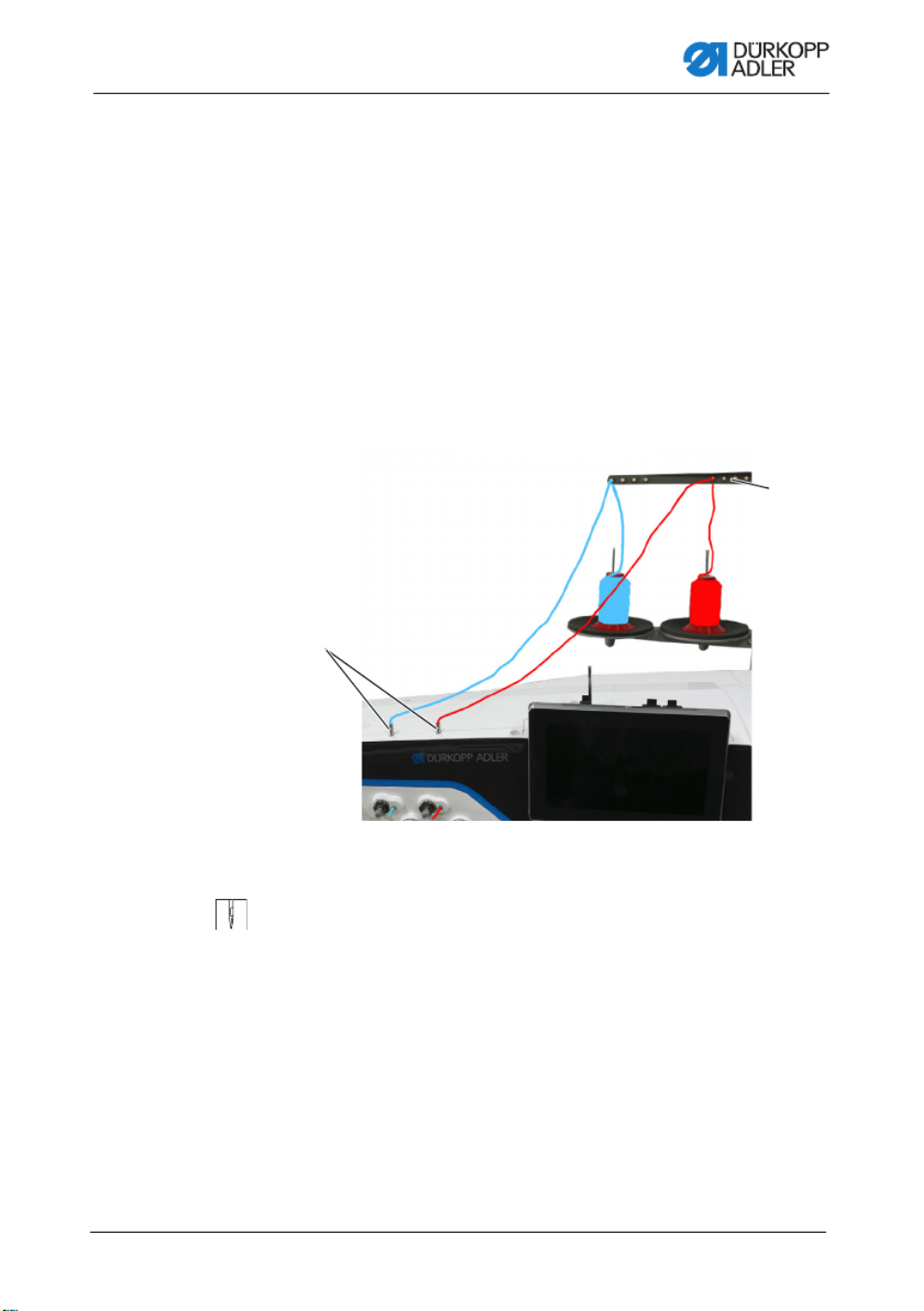
Fig. 10: Threading the needle thread (two-needle machine) (1)
To thread the right and the left needle thread:
1. Fit the thread reels on the reel stands.
The unwinding bracket must stand directly above the thread
reels.
2. Feed the left thread from the rear to the front through
the thread guide (2) on the unwinding bracket.
3. Feed the right thread from the rear to the front through
the thread guide (2) on the unwinding bracket.
(1) - Tube (2) - Thread guide on the unwinding
bracket
②
①

Operation
30 Operating Instructions D887 - 00.0 - 10/2022
Threading the left needle thread at the tensioning plate
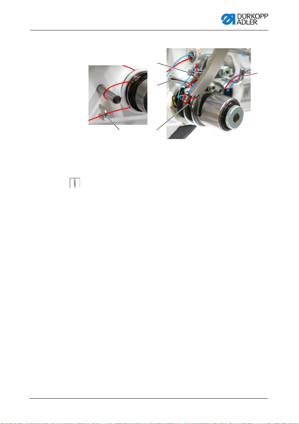
Fig. 11: Threading the needle thread (two-needle machine) (2)
4. Insert the thread from the top and guide it through the tube (1).
5. Feed the thread counterclockwise from the tube (1) around
the pretension (4).
6. Feed the thread clockwise through the rear tension (3).
Fig. 12: Threading the needle thread (3)
7. Feed the thread clockwise around the pin (6) and keep feeding
it clockwise through the front tension (5).
(1) - Tube (left thread)
(3) - Rear tension (left thread)
(4) - Pretension (left thread)
(5) - Front tension (left thread)
(6) - Pin (left thread)
(7) - Rear thread tensioning spring
(8) - Hook
①④ ③⑤
⑥
⑦
⑧
(3) - Rear tension (5) - Front tension
③
⑤

Operation
Operating Instructions D887 - 00.0 - 10/2022 31
Fig. 13: Threading the needle thread (4)
8. Feed the thread through the hook (8) and then clockwise
through the thread tensioning spring (7) from below.
9. Feed the thread around the pin (9) from left to right and then
from bottom to top through the hole of the rear needle thread
regulator (10).
(7) - Rear thread tensioning spring
(left thread)
(8) - Hook
(9) - Pin
(10) - Needle thread regulator
(left thread)
⑦
⑩
⑨⑧

Operation
32 Operating Instructions D887 - 00.0 - 10/2022
Threading the right needle thread at the tensioning plate
Fig. 14: Threading the needle thread (two-needle machine) (5)
10. Insert the thread from the top and guide it through the
tube (11).
11. Feed the thread counterclockwise from the tube (11) around
the pretension (12).
12. Feed the thread clockwise through the rear tension (13).
13. Feed the thread clockwise around the pin (15) and keep
feeding it clockwise through the front tension (14).
(11) - Tube (right thread)
(12) - Pretension (right thread)
(13) - Rear tension
(right thread)
(14) - Front tension
(right thread)
(15) - Pin (right thread)
(16) - Hook (right thread)
(17) - Front thread tensioning spring
⑰
⑮⑯
⑬
⑭
⑫
⑪
Operation
Operating Instructions D887 - 00.0 - 10/2022 33
Fig. 15: Threading the needle thread (6)
14. Feed the thread through hook (16) and over hook (8) before
feeding it clockwise through the front thread tensioning
spring (17) from below.
15. Feed the thread around the pin (9) from left to right and then
from bottom to top through the hole of the front needle thread
regulator (18).
(8) - Hook
(9) - Pin
(16) - Guide
(17) - Front thread tensioning spring
(right thread)
(18) - Needle thread regulator
(right thread)
⑯ ⑰
⑱
⑨
⑧

Operation
34 Operating Instructions D887 - 00.0 - 10/2022
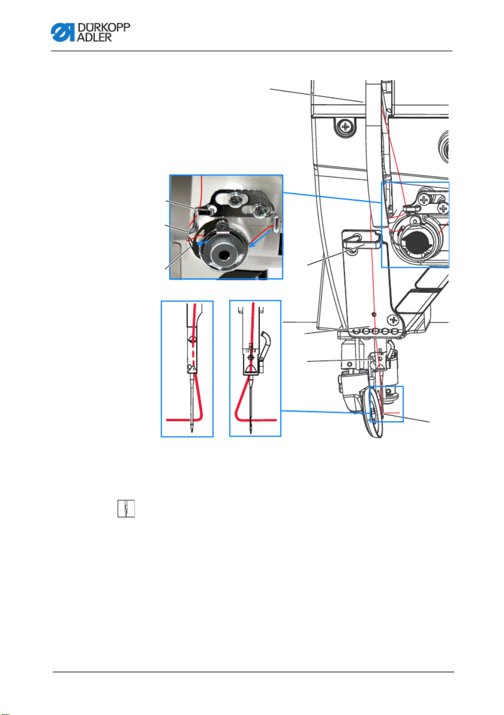
Fig. 16: Threading the needle thread (two-needle machine) (7)
16. Feed the left thread from the right to the left through the upper
hole of the thread lever (19).
17. Feed the right thread from the right to the left through the
lower hole of the thread lever (19).
18. Feed the left and the right thread through the upper thread
guide (20).
19. Feed the left and the right thread through a hole in the lower
thread guide (21).
20. Feed the threads as shown through the thread guide (22) on
the needle holder.
21. Unlock the roller foot. Insert the thread through the needle
eye (23) in such a way that the loose thread end faces the hook.
22. Pull the thread through the needle eye (23) in such a way that
the loose thread end has a length of approx. 4 cm with the
thread lever (19) at the highest position.
(19) - Holes in thread lever
(20) - Upper thread guide
(21) - Lower thread guide
(22) - Thread guide on needle holder
(23) - Needle eye
⑳
⑲

Operation
36 Operating Instructions D887 - 00.0 - 10/2022
Fig. 17: Winding the hook thread (1)
3. Feed the thread through the first two holes of the thread
guide (2): from left to right through the first hole and from right
to left through the second hole.
4. Feed the thread through the third hole of the thread guide (2)
from left to right before threading it clockwise around the
pretension (1).
5. Feed the thread to the left through the thread guide (3).
6. Feed the thread from the left to the right through the bottom-
most hole of the thread guide (3).
(1) - Pretension
(2) - Thread guide
(3) - Thread guide
① ②
③

Operation
Operating Instructions D887 - 00.0 - 10/2022 37
Fig. 18: Winding the hook thread (2)
7. Guide the thread to the winder (7).
8. Clamp the thread behind the knife (6) and tear off the loose
end behind it.
9. Fit the bobbin on the bobbin shaft (5).
10. Turn the bobbin on the bobbin shaft (5) until the drive dog
spring audibly clicks into place in the slot of the bobbin.
11. Pull the winder lever (4) up.
The winding process starts and ends automatically when
the bobbin is full. The winder lever (4) returns to its lower
position.
Information
The hook thread is normally wound on when sewing is in progress.
However, you can also wind on the hook thread without sewing,
e. g. if you require a full bobbin in order to start sewing. For this
purpose, use Bobbin Wind mode in Manual mode (p. 109).
12. Pull off the full bobbin.
13. Tear off the thread behind the knife (6).
14. Insert the full bobbin into the hook (p. 38).
(4) - Winder lever
(5) - Bobbin shaft
(6) - Knife
(7) - Winder
④
⑦
⑥
⑤

Operation
38 Operating Instructions D887 - 00.0 - 10/2022
4.7 Changing the bobbin
The bobbin change works in the same way on one-needle machines
as on two-needle machines. The only difference is that the hook
into which the bobbin is inserted is turned by 180 degrees for the
left and the right side.
Fig. 19: Changing the bobbin (1)
WARNING
Risk of injury from needle tip and moving parts!
Puncture, cutting and crushing possible.
Turn off the machine before changing the bobbin.
NOTICE
Property damage may occur!
The surface of the bobbin may become damaged, causing
the bobbin rotation monitor to stop working correctly.
Do NOT use sharp parts to remove the bobbin!
(1) - Bobbin case retainer
(2) - Recess
(3) - Thread guide
(4) - Tensioning spring
(5) - Recess
(6) - Bobbin
⑥
②
①
③ ④ ⑤
Operation
40 Operating Instructions D887 - 00.0 - 10/2022
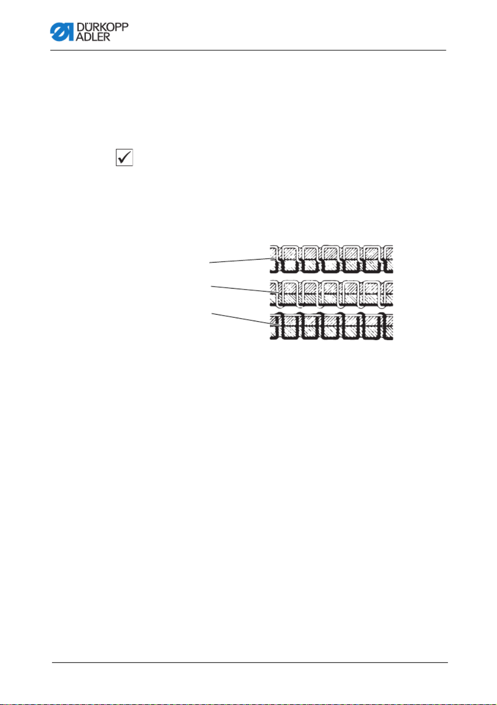
4.8 Thread tension
Together with the hook thread tension, the needle thread tension
influences the final seam pattern. With thin sewing material,
excessive thread tension can lead to undesired ruffing and
thread breaking.
Proper setting
If the tension of needle thread and hook thread is identical,
the thread interlace lies in the middle of the sewing material.
Adjust the needle thread tension so that the desired seam pattern
is achieved with the lowest possible tension.
Fig. 21: Thread tension
4.8.1 Adjusting the needle thread tension
The needle thread tension can only be set using the software of
the Commander Delta; for a detailed description, refer to the chapter
Programming (p. 57).
(1) - Identical needle thread and hook thread tension
(2) - Hook thread tension higher than needle thread tension
(3) - Needle thread tension higher than hook thread tension
DA150018_V52_XX
②
①
③

Operation
Operating Instructions D887 - 00.0 - 10/2022 41
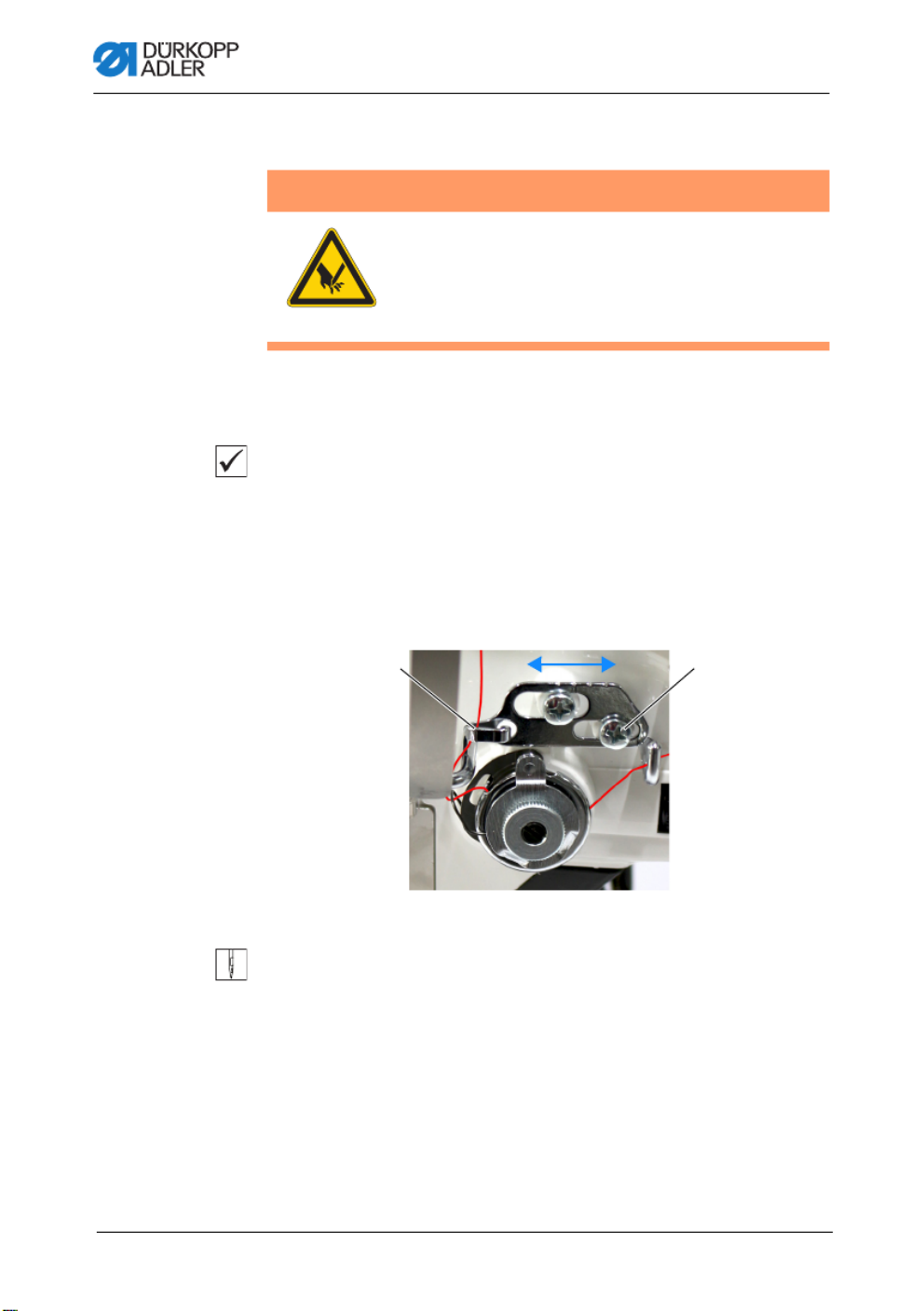
4.8.2 Adjusting the hook thread tension
Fig. 22: Adjusting the hook thread tension
The hook thread tension is generated by the tension spring (1)
and adjusted via the screw (2).
To adjust the hook thread tension:
1. Turn the screw (2).
•Increase the hook thread tension: turn the screw (2)
clockwise
•Reduce the hook thread tension: turn the screw (2)
counterclockwise
WARNING
Risk of injury from needle tip and moving parts!
Puncture, cutting and crushing possible.
Switch off the machine before adjusting the hook
thread tension.
(1) - Tensioning spring (2) - Screw
②①
Operation
42 Operating Instructions D887 - 00.0 - 10/2022
4.9 Adjusting the needle thread regulator
The needle thread regulator determines the tension applied to
guide the needle thread around the hook.
Proper setting
The loop of the needle thread slides at low tension over the thickest
point of the hook.
4.9.1 For one-needle machines
Fig. 23: Adjusting the needle thread regulator (one-needle machine)
To adjust the needle thread regulator:
1. Loosen the screw (2).
•To increase the tension: Slide the needle thread
regulator (1) to the right
•To reduce the tension: Slide the needle thread
regulator (1) to the left
2. Tighten the screw (2).
WARNING
Risk of injury from needle tip and moving parts!
Puncture, cutting and crushing possible.
Switch off the machine before adjusting the
needle thread regulator.
(1) - Needle thread regulator (2) - Screw
①②

Operation
Operating Instructions D887 - 00.0 - 10/2022 43
4.9.2 For two-needle machines
Fig. 24: Adjusting the needle thread regulator (two-needle machine)
To adjust the needle thread regulator for the left thread on two-
needle machines:
1. Loosen the screw (3).
•To increase the tension: Slide the needle thread
regulator (1) to the right
•To reduce the tension: Slide the needle thread
regulator (1) to the left
2. Tighten the screw (3).
To adjust the needle thread regulator for the right thread on two-
needle machines:
1. Loosen the screw (4).
•To increase the tension: Slide the needle thread
regulator (2) to the right
•To reduce the tension: Slide the needle thread
regulator (2) to the left
2. Tighten the screw (4).
(1) - Rear needle thread regulator
(2) - Front needle thread regulator
(3) - Screw
(4) - Screw
①③
②④

Operation
44 Operating Instructions D887 - 00.0 - 10/2022
4.10 Lifting the sewing foot
Lifting with the hand lever
Fig. 25: Lifting with the hand lever
To lift the roller foot:
1. Turn the lever (1) all the way in the direction of the arrow.
The roller foot is locked in place in the upper position.
2. Start the roller foot by returning the lever (1) to its initial
position or by using the pedal.
Information
After the roller foot has been lifted with the hand lever (1) and the
foot has been lifted, the machine can be started (e.g. for winding
the hook thread).
(1) - Hand lever
①
Operation
Operating Instructions D887 - 00.0 - 10/2022 45
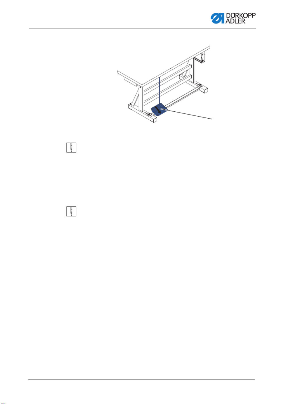
Fig. 26: Lifting with the pedal
To lift the roller foot:
1. Press the pedal (1) halfway back.
The machine stops and lifts the sewing foot.
The roller foot remains up as long as the pedal is pressed
halfway back.
OR
1. Press the pedal (1) fully back.
The thread trimmer is activated, and the roller foot is lifted.
(1) - Pedal
①

Operation
46 Operating Instructions D887 - 00.0 - 10/2022
Opening the roller foot
Fig. 27: Opening the roller foot
1. Open the roller foot in the direction of the arrow (1).
(1) - Roller foot
①

Operation
48 Operating Instructions D887 - 00.0 - 10/2022
Activating a function
To activate the function key:
1. Press the desired button.
Function is activated. The button lights up.
Deactivating a function
To activate/deactivate a function key:
1. Press the desired button again.
Function is deactivated. The button turns off.
Functions of the buttons
Button Function
Sewing backwards
When this button is activated, the machine sews in
reverse.
Positioning of the needle
When this button is activated, the needle moves to a
specific position.
This position is determined individually via the parame-
ter settings. For more information, read the
Service
Instructions.
The machine comes configured so that selecting
the button will bring the needle up.
Bartack suppression
This button cancels the general setting for sewing start
and end bartacks. If bartacks are on, pressing the but-
ton skips the next bartack. If bartacks are off, pressing
the button sews the next bartack.

Operation
Operating Instructions D887 - 00.0 - 10/2022 49
Stitch length
When this button is selected, the machine sews with
the greater stitch length that was programmed for this
stitch length on the control panel.
Value of the additional needle thread tension
Activating this button will cause the machine to sew
with the programmed additional thread tension.
Fully customizable
The button is fully customizable.
The machine comes configured so that a press of
the button will switch on the underarm lighting.
Button Function
+/–
+/–
+/–
+/–
+/–

Operation
50 Operating Instructions D887 - 00.0 - 10/2022
4.12.2 Assigning a function to the favorite buttons
You can transfer the button functions from the push button panel
to the favorite buttons. Select a function that you frequently use
so that you can switch it on faster while sewing.
Fig. 29: Assigning a function to the favorite buttons
You can assign any functions you require to the favorite buttons.
You can define the settings in the software ( p. 66).
(1) - Favorite buttons
①

Operation
Operating Instructions D887 - 00.0 - 10/2022 51
4.13 Sewing
Fig. 30: Sewing
The pedal starts and controls the sewing process.
WARNING
Risk of injury from the needle if sewing is
started unintentionally!
Puncture possible.
Do not press the pedal when your fingers are in
the area of the needle tip.
(1) - Position +1
(2) - Position 0
(3) - Position -1
(4) - Position -2
Status Processes
Before starting sewing
Initial situation • Pedal in rest position (position 0)
Machine is at a standstill.
Needle is up. Roller foot is down.
Positioning
the sewing
material
• Press the pedal halfway back (position -1).
The roller foot is raised.
• Correct the position of the sewing material.
• Release the pedal.
The roller foot is lowered onto the sewing material.
①
②
③
④

Operation
Operating Instructions D887 - 00.0 - 10/2022 53
4.14 Controlling the trimmer
4.14.1 Switching the trimmer on and off
Fig. 31: Switching on and off
Switching on
1. Press the button (1) on the control panel.
The upper knife carrier (2) is moved to the lower cutting
position along with the cutting knife (3).
Information
When set to the default settings, the drive parameters will not
cause the motor-driven knife to oscillate unless the pedal is
pressed to start the machine (can be changed).
Switch Off
1. Press the button (1) on the control panel again.
(1) - Button
(2) - Upper knife carrier
(3) - Knife
①
③
②

Programming Commander DELTA
Operating Instructions D887 - 00.0 - 10/2022 57
5 Programming Commander DELTA
5.1 Control panel Commander Delta
Fig. 34: Control panel Commander Delta
All settings in the software are performed using the Commander
DELTA control panel.
Information
If a value is entered that is not within the specified value range,
the software will automatically adopt the limit value which is closest
to your entry from the value range.

Programming Commander DELTA
58 Operating Instructions D887 - 00.0 - 10/2022
5.2 Navigating the Commander DELTA control
panel
You navigate the control panel by tapping the screen with your
fingers. There is no need for an input device.
You can open menus by pressing the corresponding button with
your finger. Swipe to switch between the different pages of the
main screen.
You can modify the information displayed in the status bar (1).
You can also adjust the tiles shown on the three pages of the main
screen (2). You customize the information using the control panel
settings, p. 84.
Fig. 35: Navigating the Commander DELTA control panel
(1) - Status bar (2) - Main screen
①
②
Programming Commander DELTA
Operating Instructions D887 - 00.0 - 10/2022 59
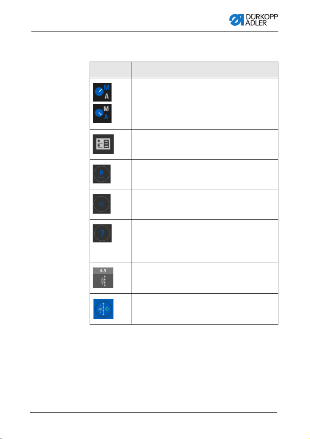
5.2.1 Symbols and buttons
Explanation of recurring symbols:
Icon Meaning
The letter shown in blue is active.
A = Automatic mode
M = Manual mode
Press the symbol to toggle between the two modes.
Programming mode (access via the burger menu),
see p. 113.
Parameters you can set in manual mode.
Burger menu
A window opens that lets you select Automatic mode,
Manual mode, Programming mode or Settings.
Context-sensitive help
Start by pressing the gray question mark before press-
ing the area for which you need help - this brings up a
pop-up window containing a Help text. Press anywhere
to make the window disappear.
Gray tiles
Parameters for which you can/must enter a numerical
value. Values can be input by pressing.
Blue tiles (stored)
You can activate or deactivate the blue tiles encircled
by a white line by pressing. You cannot set any values.

Programming Commander DELTA
Operating Instructions D887 - 00.0 - 10/2022 61
5.2.3 Navigating the burger menu
You can open the burger menu with a press of the symbol .
Fig. 36: Navigating the burger menu
5.2.4 Navigation during the start of the control panel
You can access the languages and settings without having to wait
for the control panel to finish starting up.
You can select these options as soon as their icons are displayed
on the control panel. After entering your user login, you will be
taken to the language options or the settings - depending on which
option you selected.
Icon Explanation
Language selection
Settings
to Manual mode (see p. 83)
to Automatic mode (see p. 109)
to Programming mode (see p. 113)
to the Settings (see Service Instructions)
Open tutorials
Log out user

Programming Commander DELTA
62 Operating Instructions D887 - 00.0 - 10/2022
5.3 User Configuration
The User Configuration allows the currently logged-in user to
customize the software interface to their specific needs.
To access the User Configuration:
1. Press the symbol to bring up the navigation pane.
This opens the navigation interface.
Fig. 37: User Configuration (1)
2. Press Settings (1).
This opens the Settings interface.
Fig. 38: User Configuration (2)
(1) - Settings
①
(2) - User Configuration
②

Programming Commander DELTA
Operating Instructions D887 - 00.0 - 10/2022 63
3. Press the item User Configuration (2) on the left.
You are in the User Configuration.
5.3.1 Setting the language
Here, you can set the language of the software.
Fig. 39: Setting the language (1)
To set the language:
1. Press on the language indicator (1).
A list holding the language selection opens:
Fig. 40: Setting the language (2)
2. You select the language by pressing the desired option.
The language of the control panel is changed immediately.
(1) - Language indicator
①

Programming Commander DELTA
64 Operating Instructions D887 - 00.0 - 10/2022
5.3.2 Adjusting the brightness
Here, you can adjust the brightness of the control panel.
Fig. 41: Adjusting the brightness (1)
To adjust the brightness:
1. Press on the brightness indicator (1).
2. Enter the desired value using the push button panel or
the buttons or .
The brightness of the control panel is adjusted.
(1) - Brightness indicator
①
Programming Commander DELTA
Operating Instructions D887 - 00.0 - 10/2022 65
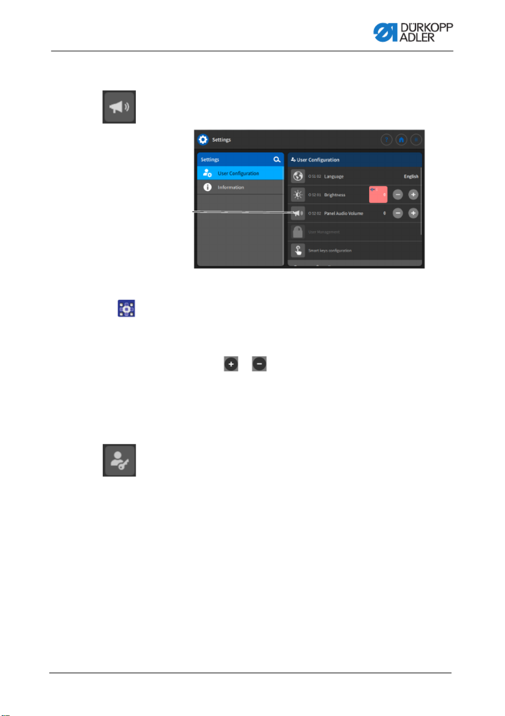
5.3.3 Setting the volume
Here, you can adjust the volume of the audio output.
Fig. 42: Setting the audio volume (1)
To adjust the audio volume:
1. Press on the audio volume indicator (1).
2. Enter the desired value using the push button panel or
the buttons or .
The volume of the control panel is adjusted.
5.3.4 User Management administration
This section is locked if you are logged in as the Default User.
Settings in User Management cannot be adjusted without extended
authorizations.
User Management administration is explained in a separate
chapter (p. 68).
(1) - Audio volume indicator
①

Programming Commander DELTA
Operating Instructions D887 - 00.0 - 10/2022 67
Fig. 45: Setting the smart keys configuration (3)
3. Press to select the function to which you wish to assign the
button.
4. Press to select Without lock or With lock.
5. Press outside the selection to exit the selection.
The adjusted settings are stored.

Programming Commander DELTA
70 Operating Instructions D887 - 00.0 - 10/2022
2. Press Settings (2).
This opens the Settings interface.
Fig. 48: User Management (3)
3. Press the item User Configuration (3) on the left.
4. Press the item User Management (4) on the right.
The user management interface opens - which may look
different depending on the user.
Fig. 49: User Management (4)
5. Define the desired settings (for explanations, see p. 71).
6. Press to return to Settings or to return to Manual mode.
(3) - User Configuration (4) - User Management
③
④

Programming Commander DELTA
Operating Instructions D887 - 00.0 - 10/2022 71
5.4.1 Authorizations as Default Technician
The factory setting for the Default Technician requires that the tech-
nician enter their username and password (technician, 25483) to log
in. If selecting User Management as a Default Technician (p. 68),
you will be presented with the following interface:
Fig. 50: Authorizations as Default Technician
On the left-hand side, you can select between the tabs (1) reserved
for roles (p. 72) and users (p. 76). Detailed explanations
are provided further below. To the right of the tabs you will find
the list (2) of created roles / users - varying with the tab (1) you
selected. On the far right, you will find the settings (3) associated
with the role/user you selected.
Explanation of role and user
(1) - Tab for roles and users
(2) - List of roles/users
(3) - Specify roles/users
Roles User
A role defines which authorizations
are permitted or forbidden.
It is possible to assign more than
one role to a single user.
You need to be a user to log in; you
cannot log in using a role.
You can log in as a user.
A user can be assigned one or
several roles - this is how they
receive their authorizations.
①
② ③

Programming Commander DELTA
72 Operating Instructions D887 - 00.0 - 10/2022
5.4.1.1 Managing roles
If selecting User Management as a Default Technician (p. 62),
you will be presented with the following interface:
Fig. 51: Managing roles
Press the tab (1) reserved for the Roles on the left-hand side.
Deleting a role
To delete a role:
1. Press the desired role.
The role is highlighted in blue.
2. Press .
The role disappears from the list; it has been deleted.
Information
Roles with a symbol behind their names have been created
at the factory. They cannot be deleted.
(1) - Tab for roles
①

Programming Commander DELTA
Operating Instructions D887 - 00.0 - 10/2022 73
Creating/deriving a new role
To create a new role:
1. Press (only a role with fewer or equal authorizations than
your own).
The list shows a new role.
2. Define the settings for the role (see table below).
Information
When logged in as a Default Technician, you can only select role
derivations up to the role of Technician. You can adjust this setting
in the authorizations of the roles (table below).
Settings of the roles
Read/Edit/Access Menu item
Programming
Access Access the programming ui
Edit Access the programming ui
Settings
Access Standard level
Access Technician level
Manual mode
Edit Status bar
Edit Main screen
Access Roles - main screen
Access Roles - status bar
Access Switch to automatic mode
Access Parameter View
Edit Manual bartack
Edit Sewing foot lift

Programming Commander DELTA
74 Operating Instructions D887 - 00.0 - 10/2022
Edit Position of the needle while adjusting the
sewing settings
Edit Bobbin Wind mode
Edit Segment abort
Edit Edge trimmer
Edit 2nd edge guide position
Edit 2nd edge guide height
Edit Edge guide reference position
Edit Stitch length
Edit Switch stitch length
Edit Needle thread tension
Edit Switch thread tension
Edit Sewing foot pressure
Edit Bartack toggle
Edit Max. Speed
Edit Half stitch
Edit Thread trimmer active
Edit Needle thread clamp
Edit Threading mode
Edit Light barrier
Edit Reset Bobbin Counter
Edit Center guide
Automatic mode
Access Program selection
Edit Stitch length correction factor
Edit Needle thread tension correction factor
Read/Edit/Access Menu item

Programming Commander DELTA
Operating Instructions D887 - 00.0 - 10/2022 77
Deleting a user
To delete a user:
1. Press the desired user.
The user is highlighted in blue.
2. Press .
The user disappears from the list; it has been deleted.
Information
Users with a symbol behind their names have been created
at the factory. They cannot be deleted.
Creating a new user
To create a new user:
1. Press .
The list shows a new user.
2. Define the settings for the user (see table below).
Settings of the user
Icon Settings Explanation
General
First name Name of the user, NOT to be
confused with the data used
for logging in!
Name
Authorization
Login with username and
password
On/Off
Username
Name for logging in
Password
Password for logging in

Programming Commander DELTA
84 Operating Instructions D887 - 00.0 - 10/2022
5.6.1 Setting up the user interface
You can customize the arrangement of the tiles and the appear-
ance of the status bar in Manual mode.
Arranging the tiles on the main screen
The main screen consists of three pages, which you can customize
to your individual needs.
To adjust the tiles on the main screen:
1. Press the symbol to bring up the navigation pane.
This opens the navigation interface.
Fig. 56: Setting up the user interface (1)
2. Press Settings (1).
This opens the Settings interface.
(1) - Settings
①

Programming Commander DELTA
88 Operating Instructions D887 - 00.0 - 10/2022
Fig. 62: Setting the parameters
(1) - Search
(2) - Parameters cross-segment
(3) - Parameters Segment End
(4) - Parameters Segment
(5) - Parameters Segment Begin
(6) - Context-sensitive help
①
②
③
⑤ ⑥
④

Programming Commander DELTA
Operating Instructions D887 - 00.0 - 10/2022 93
Software / Stitch Counter
In Software mode, the bobbin
is monitored by the software
based on the number of stitches
sewn.
Counter Type
4 different counters can be applied.
The following 3 sub-items can be
set for each of the counters.
Value range
A/B/C/D
Counter value
Bobbin supply capacity in stitches.
This is a very variable value, which
depends on the size of the bobbin
and the thickness of the thread.
Value range
0 to 99999 [stitches]
Sewing stop
Sewing stops and a notice is shown
on the display when the bobbin is
detected to be nearly empty. If the
parameter is not activated, only the
LEDs on the machine arm give a
warning if the bobbin is empty.
Value range
On/Off
Sewing foot lower position Value range
On/Off
Reset necessary
It is only possible to resume sewing
after changing the bobbin and con-
firming the message on the control
panel.
Value range
On/Off
Menu item Setting option 1 Setting option 2
Produktspecifikationer
| Varumärke: | Durkopp Adler |
| Kategori: | Symaskin |
| Modell: | D887 |
Behöver du hjälp?
Om du behöver hjälp med Durkopp Adler D887 ställ en fråga nedan och andra användare kommer att svara dig
Symaskin Durkopp Adler Manualer

4 Mars 2025
20 Oktober 2024
17 Oktober 2024
17 Oktober 2024
13 Oktober 2024
11 Oktober 2024
6 Oktober 2024
28 September 2024
23 September 2024
23 September 2024
Symaskin Manualer
- Symaskin AEG
- Symaskin IKEA
- Symaskin Medion
- Symaskin Siemens
- Symaskin Ambiano
- Symaskin Alfa
- Symaskin Brother
- Symaskin Silvercrest
- Symaskin Tristar
- Symaskin Livoo
- Symaskin Bestron
- Symaskin Sinbo
- Symaskin Jata
- Symaskin Emerio
- Symaskin Singer
- Symaskin Bernina
- Symaskin Pfaff
- Symaskin Blaupunkt
- Symaskin Juki
- Symaskin Solac
- Symaskin Elna
- Symaskin Termozeta
- Symaskin Jocca
- Symaskin Kenmore
- Symaskin Guzzanti
- Symaskin Easymaxx
- Symaskin Toyota
- Symaskin Husqvarna
- Symaskin Bernette
- Symaskin Janome
- Symaskin Necchi
- Symaskin Yamato
- Symaskin Kayser
- Symaskin RCE
- Symaskin Privileg
- Symaskin Lifetec
- Symaskin Kunft
- Symaskin Veritas
- Symaskin Union Special
- Symaskin Easy Home
- Symaskin Carina
- Symaskin Lervia
- Symaskin Vendomatic
- Symaskin Home Electric
- Symaskin Baby Lock
- Symaskin Empisal
- Symaskin Crofton
- Symaskin Lewenstein
- Symaskin Durabase
- Symaskin Meister Craft
- Symaskin Micromaxx
- Symaskin Yamata
- Symaskin Weasy
- Symaskin Łucznik
- Symaskin Silver
- Symaskin Victoria
- Symaskin Prince
- Symaskin Hofmann
- Symaskin Kohler
- Symaskin Muller
- Symaskin Sinojo
- Symaskin Huskystar
- Symaskin Gritzner
- Symaskin LERAN
- Symaskin W6
- Symaskin Prixton
- Symaskin Primera
- Symaskin Zippy
- Symaskin Feiyue
- Symaskin Mediashop
- Symaskin ER
- Symaskin Novamatic
- Symaskin Siemssen
- Symaskin Mio Star
- Symaskin Husqvarna-Viking
- Symaskin SteamMax
Nyaste Symaskin Manualer
8 April 2025
5 Mars 2025
1 Mars 2025
25 Februari 2025
25 Februari 2025
25 Februari 2025
25 Februari 2025
18 Februari 2025
17 Februari 2025
12 Februari 2025