Ganz PixelMaster NR4HL Bruksanvisning
Ganz
övervakningskamera
PixelMaster NR4HL
Läs nedan 📖 manual på svenska för Ganz PixelMaster NR4HL (105 sidor) i kategorin övervakningskamera. Denna guide var användbar för 4 personer och betygsatt med 4.5 stjärnor i genomsnitt av 2 användare
Sida 1/105


᧮
CONTENT
OVERVIEW PLAY
3 Before Installation 62 If you want to play
4 Key Features
6 Front Panel
7 Rear Panel
8 Remote Control At a Glance
INSTALLATION ARCHIVING
10 Basic Layout 65 To start the Archive menu
11 Connecting to an external devices
MONITORING WEB VIEWER
18 Start up/Shutdown 68 What is the Web Viewer?
20 Live Screen At a Glan 70 Live
74 Search
76 Setup
SYSTEM SETTING MOBILE VIEWER
26 To move to the System Setup menu 88 GanzView
27 Camera Setting
30 Display Setting
33 Audio Setup
34 User Setting
36 Network Setup
39 System Setting
43 Storage
45 Event Setup
RECORD SETTING ARCHIVE VIEWER
52 To start the Record Setup menu 99 Getting started with the Backup Play
52 Record Setup 100 Backup Player At a Glance
SEARCH APPENDIX
58 To move to the Search menu while 103 Specification
in monitoring
58 To move to the Search menu while
in playback mode
59 Search Settings

᧯
OVERVIEW
Before installation
Comply with the following instructions to prevent a fire, explosion, system failure shock. or electric
Remove the power supply module before proceeding.
Check the input voltage (AC100VದAC240V) to the power supply module before connecting it.
Keep the product away from humidity.
Ensure that all devices connected to the product should be properly earth-grounded.
In operation mode
Comply with the following instructions to prevent a fire, explosion, system failure or electric
If you need to open the cover, consult with a service person who could help you do what you
want to do.
Do not connect multiple devices to a single power socket.
Keep the product away from dust or too much combustible substances (ex: propane gas).
Do not touch it with wet hand.
Do not insert a conductor in the vent of the ventilation system.
Do not apply excessive force to unplug the power cord.
Disassembly & Cleaning
When cleaning on the surface, use a dry cloth.
Do not wipe the product using water, paint thinner or organic solvents.
Do never dismantle, repair or modify the product by your own.
During installation
To prevent an accident or physical injury and to operate NVR properly, please comply with the
followings
Secure at least 18 centimeter of distance between cooling fan and wall for a proper ventilation.
Install the product on a flat surface.
Keep it away from direct sunlight or excessive temperature.
While in use
Do not apply force to or shake it while using it.
Do not move, throw away or put excessive force to it.
Using any unrecommended HDD may cause a system failure. Check the compatibility list and
use only compatible HDDs.
{A system failure or data loss caused by an incompatible HDD will void your warranty.}

᧰
OVERVIEW
Key Features
This product allows you to receive audio and video signals from a max of 4/8 CH 1080p H.264
network camera before
saving them to the internal HDD. Besides, you can also transfer them to an external device that can
be monitored on your PC
or mobile phone remotely
Display the video from up to 4/8 CH 1080p network camera in real time (Max 120/240 fps)
Save the video from up to 4/8 CH 1080p network camera in a max of 32/64Mbps (8Mbps
per channel) (Max 120/240fps)
Play up to 4/8 CH 1080p video in real time (Max 120/240 fps)
H.264 BP/MP/HP network camera supported(BP: Baseline profile, MP: Main profile, HP:
High profile)
4/8 built-in port, PoE switching hub (40W/72W)
ಫPlug & Play’ camera connection
Protect the IP camera via secured closed circuit LAN environment
Auto notification with self diagnosis (HDD S.M.A.R.T, temperature, network connection
status,fan error, etc.)
Dual streaming supported for a remote display
Auto resolution & FPS adjustment for a remote service
External eSATA HDD supported – various search methods (time, event, bookmark and
thumbnail)
Mass storage backup via USB port or FTP server
Dedicated smart phone applications that can be used with iPhone and iPad or on Android
OS
1080p Full HD GUI

᧱
OVERVIEW
What's included
Mouse Remote Control x1 Power Cable x2
& Batteries (AAA x2)
DC 12V Adaptor DC 48V Adaptor Screws
Adapter cable retainer clip x2 User manual CD Quick Guide

᧲
OVERVIEW
Front Panel
Name Description
IR Remote
Control
Receiver
Receive the signal from the remote control
USB Used for connecting USB storage or mouse.
Status LED Show the status of power,recording or network connection
together with the corresponding alarm.

᧴
OVERVIEW
Remote Control At a Glance
LOGOUT
LOGOUT
POWER
Turn on or off the power. PANIC
Start the emergency recording.
SEARCH
Display the search window. ALARM
Show the alarm status with
a popup window.
ARCHIVE
Display the backup window. SETUP
Display the system setup menu.
Channel
Function as channel selection
button in live or playback mode.
Or used for entering the password. ID
Set the remote control ID.
DISPLA
Y
Switch the split mode.
SEQ
Switch to sequence mode.
SNAPSHOT
Turn on or off the power.
Used to change the direction
or adjust the play speed
in playback mode.
EXIT
Exit from the current screen
and return to the previous
screen.
ENTER
Select a menu item or apply
your settings.
LOG
Display the log list.
KEYLOC
K
Lock any operation on the unit.
AUDIO
Display the audio channel
Selection window.
RESERVE
Turn on or off the power.
MENU
Display the tool bar on the live
screen.
Use to move through the menus
PTZ/ZOOM
Enter the PTZ or digital zoom
Mode and control the operation.

᧵
OVERVIEW
Change the remote control ID
The remote control will be active only if the remote control ID matches with that specified on the
NVR.
If multiple NVRs are installed on one place and you have just a single remote control, use the ID
button to set the remote control ID. Only the ID-matching NVR can be controlled.
1. From <SYSTEM> - <CONTROL DEVICE> under the System Setup menu, set the
<REMOTE CONTROLLER ID> and press <Apply>.
Select between 00 and 99. For more details, refer to <SYSTEM SETUP>.
The remote control will be active only if the remote control ID matches with that of the
NVR's system ID.
2. Press the [ID] button on the remote control. The default remote control ID is 00.
3. Use the number buttons to provide a two-digit ID. If you want to enter 01, for instance,
enter the number 0 and 1 in sequence.
Check if the remote control ID is set properly by manipulating the remote control.
4. To reset the ID to 00, press and hold the [ID] button.

᧭᧬
INSTALLATION
Basic Layout
Precautions
To secure recording stability from an overloaded network traffic , hacking attempt or DoS (Denial
of Service) attack, only the direct cable connection between camera and NVR is allowed.
Any access from an outside PC to the IP camera will be strictly prohibited for the purpose of
secure operation.
9 Signal connection for POS and ATM is scheduled to be upgraded later.
Camera
Network
Attached
Storage
CMS
Web viewer
Mobile viewer
Full HD
monitor
eSATA
Stora
g
e
Speaker
MIC
Sensor Alarm
Control
Device
POS
ATM
Access
Controlle
r

᧭᧭
INSTALLATION
Connecting to an external device
Connecting to the monitor
This product supports only monitor models featuring 1080p 60Hz HDMI or DVI input.
Connect the HDMI cable between HDMI output port in the bottom rear panel and HDMI port of the
monitor, or use the
HDMI to DVI cable to connect to the DVI port of the monitor.
Power Connection
Two adaptors are provided: one for NVR operation (DC 12V), and the other for PoE (Power Over
Ethernet, DC48V).
NVR power connection
Plug the provided DC 12V adaptor in the rear power port of the NVR.
PoE Switching hub power connection
Plug the provided DC 48V adaptor in the rear power port of the NVR.
When done, attach the adaptor cable clip to the rear panel and insert the cable in.
Make connection when the power is not applied yet.
Arrange up the cables and be careful not to peel off the cable coating.
Do not place the power cord under the carpet or rug. The power cord is usually earth-
grounded. However, even
if it's not earth-grounded, do never modify it on your own for earth-grounding.
Do not insert multiple devices in a single power socket. Otherwise, it may cause a power
overload.
For stable power supply, this product provides two separate adaptors and two
corresponding AC cords by factory default. Make sure all cables are connected properly.
DC48V adapto
r
DC12V adaptor
Adaptor cable
retainer clip

᧭᧮
INSTALLATION
Connecting the camera
You can connect a PoE-featuring IP camera to the rear [CAM1]~[CAM8], RJ45 port using the CAT5
10/100Mb Ethernet cable without a separate power source.
Precautions
To secure recording stability from an overloaded network traffic , hacking attempt or DoS (Denial
of Service) attack, only the direct cable connection between camera and NVR is allowed.
9If the IP camera provides the alarm I/O port or Audio I/O port, you can make alarm or
audio connection. For more details, refer to the user manual of the IP camera.
The Ethernet connection is effective within 100 meter in distance. Beyond that, you may
encounter a data loss or failure to connect to the camera. If you need to make cable
connection of longer than 100 meters, use a separate PoE extender for cable extension.
The total power consumption of the IP cameras should not exceed the rated power capacity
of the 48V PoE adaptor. Beyond that, the video may not be played properly or no video will
be displayed at all. If this is the case, use a separate (additional) power source for supplying
power to the cameras.
For stable operation, a dedicated communication line is established for IP cameras in the
same network. This is why network router or hub connection is not allowed.
Camera HUB or Router NVR

᧭᧯
INSTALLATION
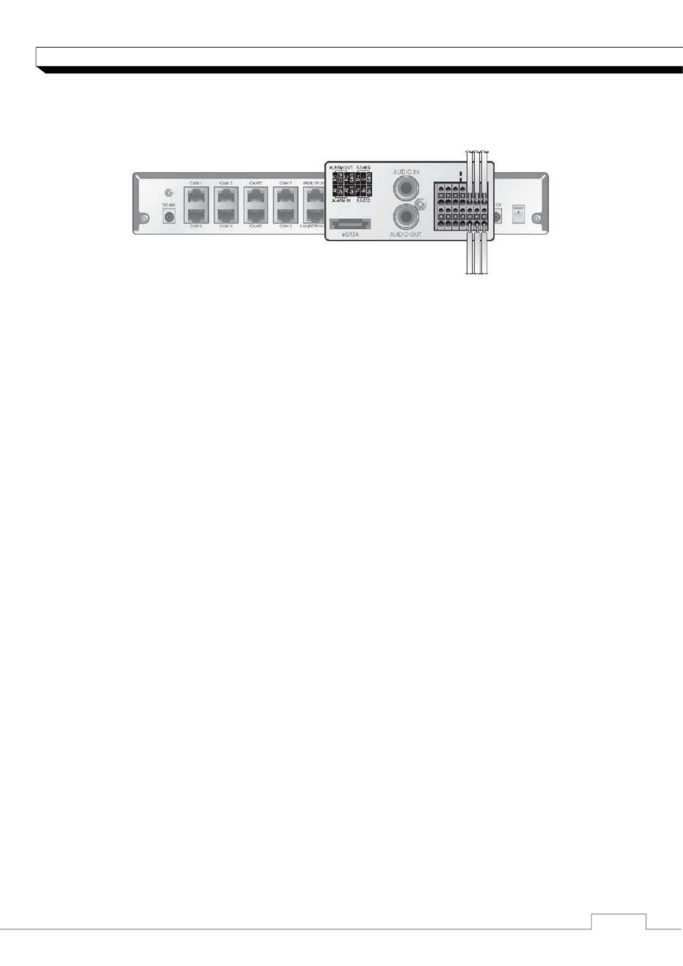
Alarm I/O Connection
connect the alarm input signal
1. While pressing and holding the [A1] or port button in the rear bottom of the NVR, [A2]
insert the alarm signal cable in the hole under the button.
2. Insert the grounding wire in the [GND] port.
3. To ensure secure connection, release the button and pull out the wire to check if it's not
pulled out.
4. To remove the wire, pull it out while holding the upper button.
To connect the alarm output signal
Connect the signal line of an alarm output device to the rear [ALARM OUT] port.
1. Check the relay output type of Normal Open or Normal Close before selecting a proper
type (N/O or N/C). While holding the [N/O] or [N/C] button, arrange the alarm signal cable
through the hole under the button.
9 N/O(Normal Open) : normally Open but switching to Close if an alarm out occurs.
9 GND : Insert the grounding wire.
9 N/C(Normal Close) : normally Close but switching to Open if an alarm out occurs.
2. Insert the grounding wire in the [GND] port.
3. To ensure secure connection, release the button and pull out the wire to check if it's not
pulled out.
4. To remove the wire, pull it out while holding the upper button.
᧭᧰
INSTALLATION
Communication Port
RS-485 Connection
Connect the keyboard controller.
You can connect a text-in device such as POS or ATM. After connecting the control device, be sure
to match the connection settings between NVR and device. Make communication settings in
<Control Device>. (page 43)
1. Use the signal line to make connection between [D+] of the rear NVR and [D+] of the
keyboard controller.
2. Make connection between [D-] of the rear NVR and [D-] of the keyboard controller.
3. Connect [GND] on the rear of the NVR to [GND] of the keyboard controller.
9 For RS-485 connection, refer to the user manual of the keyboard controller.
9 Signal connection for POS and ATM is scheduled to be upgraded later.
RS-232 Connection
You can connect a text-in device such as POS or ATM.
For connection of the text-in device, refer to the user manual of the text-in device.
9 Signal connection for POS and ATM is scheduled to be upgraded later.
Audio Device Connection
You can connect an audio output device such as speaker amplifier.
Connect the audio input device such as microphone to the rear Audio In port, connect the audio
output device such as speaker amplifier to the Audio Out port.

᧭᧱
INSTALLATION
eSATA Storage
If the internal storage space is insufficient, you can extend your storage capacity by adding an
eSATA storage device to the rear eSATA port.
9 Recording may not be enabled with an incompliant eSATA storage. For the compatibility list,
contact the retailer of the eSATA storage.
USB Device
You can connect a USB storage device for saving the video, updating the firmware,
importing/exporting user data or settings. You can also connect the USB mouse to control all
operations of the NVR.
If you need to connect a USB HDD with a high power consumption, it is recommended to
use a separate power source for that HDD.
External HDD
(For backup only)
USB Stora
g
e Mouse
᧭᧲
INSTALLATION
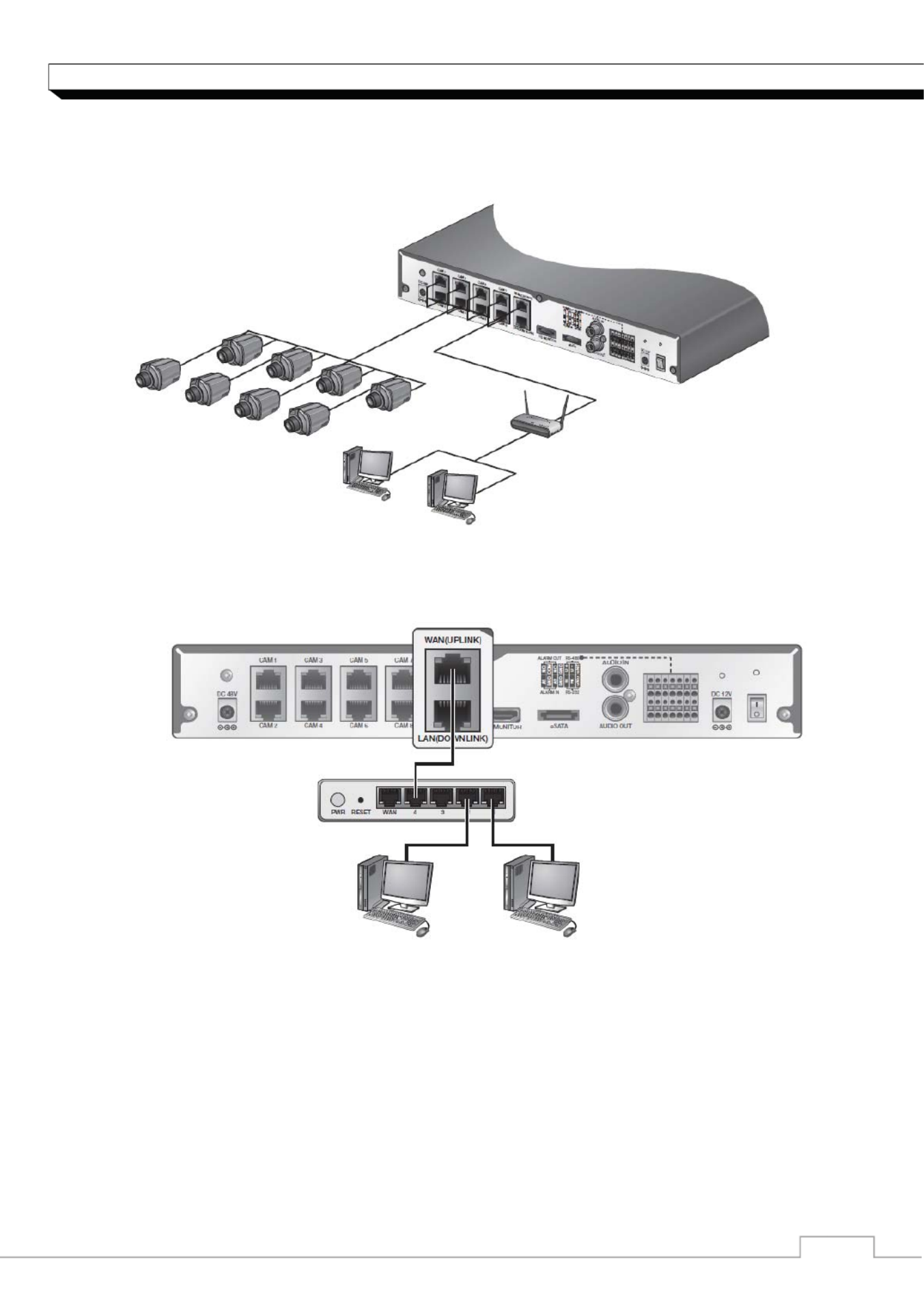
Network Connection
PC connection in the local network
You can connect NVR to a PC in the same network and control or manipulate it on the PC monitor.
1. Connect the [WAN(UPLINK)] port in the rear panel to the router or hub.
2. Connect the local PC to the router or hub.
3. Enter the address in the address bar (web browser) of the local PC or of the dedicated
software program in the format of ಯhttp://IP address:web service port ರ.(Ex : http://192.168.
1.23:8080) The web service port is set to 8080 by default. From the Network Setup screen,
you can change the port number.
4. Provide the ID and password before logging in. Then, you can view the monitoring screen.
5. Access ID (factory default) : ADMIN, P/W : 1234.
9 For the security purpose, change the password right after you purchased the product.
Camera1
Camera2
Camera3
Camera4
Camera5
Camera6
Camera7
Camera8
Local PC
Local PC
Broadband Router
Or
Hub
Broadband Router or Hub
Local PC Local PC

᧭᧳
INSTALLATION
PC connection from a remote network
You can connect NVR to a PC or mobile device in the same remote network and control or
manipulate it on the monitor of the PC or mobile device
1. Connect the [WAN(UPLINK)] port in the rear panel to the router.
2. Connect the [WAN(UPLINK)] port of the router directly to the fixed IP LAN cable, or
connect it to the ADSL modem.
3. If using the router, set the port forwarding and enter the DDNS address in the address bar
(web browser) of the remote PC, or of the dedicated software program or mobile phone.
For the IP and DDNS address settings, refer to “Network Setup”. (page 37)
4. If the MAC address of the NVR is 00-1C-B8-12-34-56 and the web port number is 8080,
enter "http://001CB8123456.dvrlink.net:8080" in the address bar of the web browser.If you
have renamed DDNS as “mydvr”, you can make network connection
athttp://mydvr.dvrlink.net:8080
Local PC
Local PC
Broadband Router
ADSL Modem
Direct Connection
Remote PC
Smart Phone
Broadband Router
Local PC
ADSL Modem

᧭᧴
Monitoring
Start Up/ Shutdown
START
You can connect NVR to a PC in the same network and control or manipulate it on the PC monitor.
1. Connect the adaptor to the 48V PoE power input
port in the rear panel of NVR.
9 Make connection when the power is not applied yet.
2. Connect the adaptor to the 12V power input port in
the rear panel of NVR.
3. Turn on the power switch in the rear panel of NVR.
With a beep, the logo screen appears several
seconds after the front LED turns on.
4. When the booting process is completed, the live
screen then the login screen appears.
Log In
To manipulate or access the menus of NVR, you should have logged in.
1. When the system starts, the login screen appears.
2. Select a user and provide the password.
The default password of the "ADMIN" account is
"1234".
3. Click <OK>.
If the login information is correct and valid, you will
see the live screen.
9 For the security purpose, change the password right
after you purchased the product.
.
Log Out
To prevent unauthorized access, it is recommended to log out when you leave the screen.
9 Hover the cursor near the bottom of the screen to display the menu.
1. In the monitoring screen, click <MENU> in the
bottom left corner of the screen to <LOG OUT>, or
press the [LOGOUT] button on the remote control.
2. 2Access to Search / Backup / System Setup /
Record Setup / System Shutdown will be restricted.

᧭᧵
Monitoring
System Shutdown
You can connect NVR to a PC or mobile device in the same remote network and control or
manipulate it on the monitor of the PC or mobile device
1. In the monitoring screen, click <Menu> in the
bottom left corner of the screen to <SHUTDOWN>
the system, or press the [POWER] button on the
remote control.
2. Use the virtual keyboard to enter the password.
3. Be sure to turn off the power switch in the rear
panel.
9 If you turn off the system in an abnormal manner
such as removing the power cord while the system
is in operation, the disk will have or increase the
bad sectors, causing data loss and shortened life cycle of the disk.

Status Bar
Press the Ⴍ button on the remote control, or place the mouse in the lower area of the screen to
display the status bar.
ITEM Description
Menu Button Select one of the system setup, search and backup menu items
before accessing it.
User ID Show the ID of the user who has currently logged in.
Screen
Control
Buttons
Change the screen layout so that both status bar and timeline are
displayed at all times.
Select a split mode.
Select Auto Sequence or Special Split Mode.
Display or hide the OSD menu on the screen.
PTZ Move to the PTZ screen. You can control the PTZ operations of a
PTZ-compliant camera on the PTZ screen.
Zoom Move to the Digital Zoom.
Quick Log Display the log list of the recent recording events.
Audio
Channel
Selection
Button
You can use the camera supporting the audio input to listen to the
audio.
Microphone
Channel
Selection
Button
Select a camera to which the audio signal will be transferred from the
connected microphone.
Panic Record Start the panic recording.
Alarm Indicator
Turns on if an event occurs. It does not turn on if no reaction to the
event is yet defined.
Click this to check the information of the event that occurred.
Network
Connection
Status
Check if network connection is made via an external PC or mobile
device. Click this to view the details of the concurrent users and to
check the network connection status. For more information, refer to
"Network Setup". (page 36)
Disk Space
Show the disk space information. If you have set the disk overwrite m
ode, it will be displayed "OW" (Over Write) from the start point of the
overwriting. Click this to viewthe details of the disk status. For more
information, refer to "Record Setup".
Date & Time Display the current time and date.

᧮᧯
Monitoring
Using the status bar in the live mode
Selecting a split mode
Click a desired split mode from 1, 4, 9, 6 and 8 split screen. Or press the [DISPLAY] button on the
remote control until a desired split mode is displayed.
9 4CH NVR model support only 1- and 4-split screen modes.
Auto sequence
Click the Sequence button in the status bar, or press the [SEQ] button on the remote control to
perform the specified sequence mode.
You can configure the sequence settings in
<SEQUENCE>.
For details, refer to ಯSequenceರ. (page 31)
Zooming
You can enlarge the monitoring screen for better view.
Zooming will enlarge the video of the selected channel. If no channel is selected, channel 1 will be
zoomed.
1. Click Zoom in the status bar or move the cursor
to a desired channel and right-click it to display
the context menu. Select <ZOOM>.
You can also press the [ZOOM] button on the
remote control.
2. Move to the zoom control screen. When the
menu bar appears in the right bottom, use the
buttons to control the zooming.
Select a channel to zoom in/out.
Zoom out the current (enlarged) image step by step.
Enlarge the current image step by step.
Zoom Box : Use the yellow box to move to or select a desired zooming area.
Exit the zooming screen and return to the live screen.
᧮᧰
Monitoring
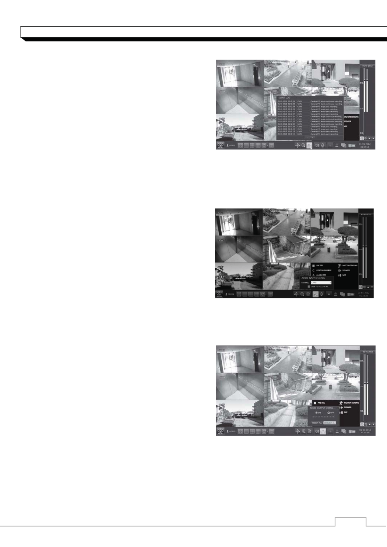
To check the event log
You can check the log of the events that occurred.
1. Click Log to display the “EVENT LOG” window.
The log list is sorted with the latest one on top.
2. Double-click a desired log to display the event
video.
You will move to the play screen of the selected
log.
To select an audio input channel
Select a channel from which the audio signal will be
received.
If you check the <LINK TO FULL SCREEN> option
and change the 1-split screen, the audio signal will be
sync with the selected channel.
9 Even if a channel to syn with is already selected,
checking the <LINK TO FULL SCREEN>
optionwill receive the audio signal only from the
selected1-split screen regardless of the previous
setting.
To select an audio output channel
You can select a camera outputting the voice signal
from the microphone that is connected to NVR.
᧮᧱
Monitoring
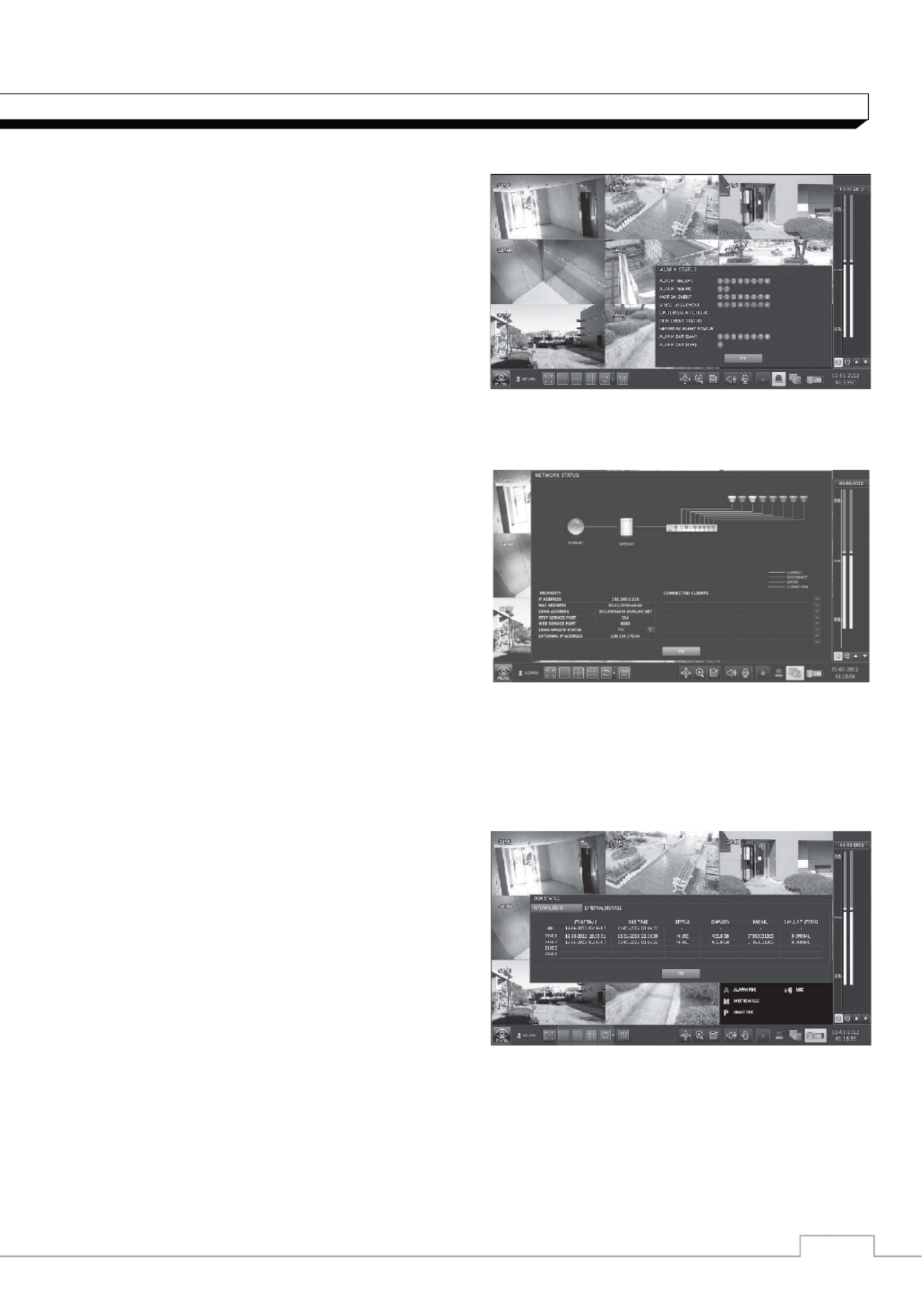
To check the alarm status
You can check the alarm status of each camera.
Click <OK> to close the window
To check the network status
You can check the network connection status.
Click <OK> to close the window.
9 For more information, refer to "Network Status".
(page 38).
To check the disk status
You can check the storage space of the current disk
and check also if there is any problem with the disk.
Click <OK> to close the window.
For more information, refer to "Disk Information".
(page 43).

᧮᧲
System Setting
To move to the System Setup menu
How to use the mouse
How to use the remote control 1
How to use the remote control 2
.

3. Click <ADVANCED> and configure the display
settings in detail for each camera as necessary.
9 The advanced setting items may differ
depending on the camera model.
4. To apply the change, click <APPLY> in the
bottom of the screen.
5. When done, press the [EXIT] button on the remote
control or click <CLOSE> in the lower screen.
The confirmation message appears and you will
return to the previous menu.
It is advisable not to change the <ADVANCED>
settings once you completed the initial settings properly.
Covert Setup
You can set to hide the camera video so that
a specific user or user group can not view.
Set a channel(s) that you want to hide from a specific
user or user group.
1. From <SYSTEM SETUP> - <CAMERA>, select
<COVERT SETUP>.
2. Use the [ʆʈُٙ/ENTER] buttons on the remote
control or use the mouse to select a covert
channel(s) from a specic user group.
>ADMIN, MANAGER, USER : Set them to <ON>.
The selected channel will be hidden from the applicable user account.
>LOGOUT : Set it to <ON>. When the user logs out, the selected channel will not be displayed.
3. Select display title on live view screen for covert channel either “COVERT” or “NO VIDEO”
To activate this settings, user need to logoff then login NVR again.
4. To apply the change, click <APPLY> in the bottom of the screen.
5. When done, press the [EXIT] button on the remote control or click <CLOSE> in the lower
screen.
The conrmation message appears and you will return to the previous menu.
To change the covert settings from user group to user, move to the <USER> menu and make
necessary changes. (page 34)
Motion Sensor
Set the motion sensor of the camera so that it can
detect a motion event.
1. From <SYSTEM SETUP> - <CAMERA>, select
<MOTION SENSOR>.
2. Use the [ʆʈُٙ/ENTER] buttons on the remote
control or use the mouse to specify the use of each
option item.
> ACTIVATION : turn on or off the motion sensor.
> MOTION MARK: Set it to <On>.
The video window will display the motion mark if a motion is detected.
᧮᧵
System Setting
> SENSITIVITY : Set the sensitivity level of the motion sensor to either Daytime or Nighttime.
> MINIMUM BLOCKS : Set the minimum number of blocks (that will be considered an event) to
Daytime or Night if a motion is detected in several blocks in the motion sensor area.
> AREA SETUP : Specify the motion detection area.
3. To apply the change, click <APPLY> in the bottom of the screen.
4. When done, press the [EXIT] button on the remote control or click <CLOSE> in the lower
screen. The confirmation message appears and you will return to the previous menu.
9 The above options such as <SENSITIVITY> and <MINIMUM BLOCKS> and how to set
the motion area may be restricted
9 depending on the specication of the connected camera.
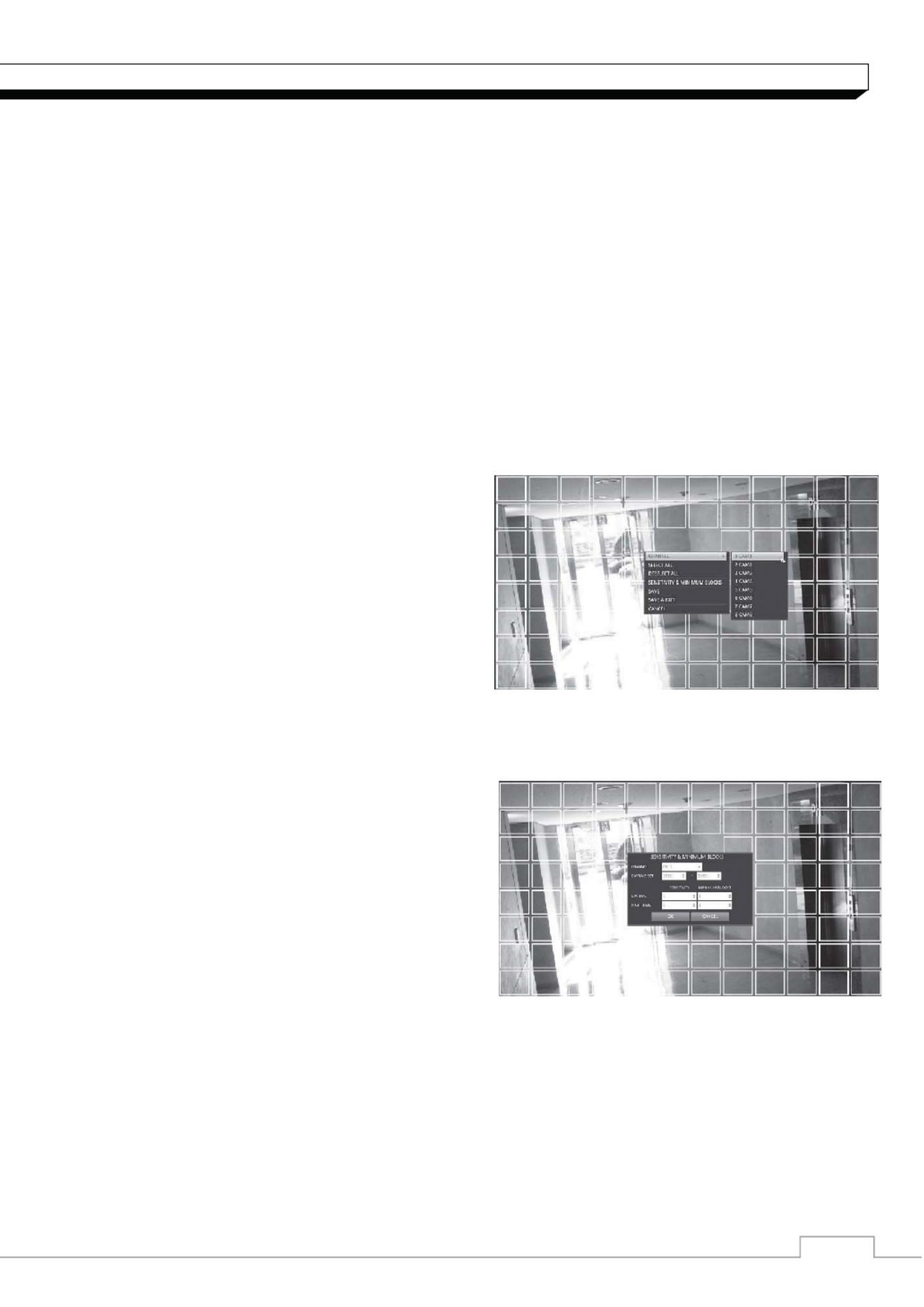
Motion Area Setup
From the motion setup window, click <AREA SETUP> in the right corner to display the area setup
screen. Setting the motion area may differ depending on the camera model. Below is a typical
setting of the motion area.
1. Click <AREA SETUP> to move to the motion
area setup screen.
2. If using the remote control, press the [ENTER]
button to mark the current position.
3. Use the arrow buttons to move to a desired block
and press [ENTER]. The area setup will begin.
Then, use the arrow buttons to specify the area.
Alternatively, you can use the drag-and-drop
method to specify or release the area as using
mouse.
4. If you select the specified area again, it will be
released.
5. Press the [EXIT] button on the remote control or
right-click any area to display the popup window
as in the right picture.
6. From the popup window, move to and specify the
<SENSITIVITY> and <MINIMUM BLOCKS>
for the current channel.
> CHANNEL : select a channel that you specify
the sensitivity and minimum blocks for.
>SENSITIVITY : 1(Low) ~ 10(High) - The higher
the number is, the more higher the sensitivity
level becomes.
>MINIMUM BLOCKS : 1(High) ~ 10(Low) - The
lower the number is, the higher the sensitivity level becomes.
> DAYTIME SET : specify the time period that will be considered as daytime.
> DAYTIME : specify the <SENSITIVITY> and <MINIMUM BLOCKS> for the daytime.
> NIGHTTIME : specify the for the nighttime. <SENSITIVITY> and <MINIMUM BLOCKS>
Images recorded in a low contrast scene such as at night cause severe noise, triggering the motion
event too often.
If this is the case, reduce the nighttime sensitivity to a degree.

᧯᧬
System Setting
Display Setting
You can configure the display settings regarding the OSD menus, monitor and sequence.
OSD
Configure the settings for the time, title, boundary, icon and language that will be displayed on the
screen.
1. From <SYSTEM SETUP> - <DISPLAY>,
select <OSD>.
2. Use the [ʆʈُٙ/ENTER] buttons on the remote
control or use the mouse to set each option of the
OSD item.
> CAMERA TITLE : specify the display of the
camera title on the screen.
> RECORDING MODE ICON : specify the display
of the record mode icon on the screen.
> AUDIO ICON : specify the display of the audio
icon on the screen.
> STATUS BAR ON FULL SCREEN MODE : select to show or hide the status bar in full screen
mode.
- AUTO HIDE : place the cursor in the lower area of the screen to display the status bar.
If moving the cursor up, the status bar will disappear.
- ALWAYS ON : The status bar will be displayed at all times.
- 5 SEC ~1 MIN : If no mouse movement is detected for from 5 seconds to 1 minute, the status
bar will disappear.
> TIMELINE ON FULL SCREEN MODE : select to show or hide the timeline in full screen mode.
- AUTO HIDE : place the cursor in the right corner to display the timeline. If moving the cursor to
the left, the timeline will disappear.
- ALWAYS ON : The timeline will be displayed at all times.
- ALWAYS OFF : The timeline will not be displayed.
> BORDER LINE : specify the display of the cross-border between channels in a split mode
> BORDER COLOR : select a color for the border.
> USER NAME : specify the display of the currently logged-in users on the status bar.
> LANGUAGE : select a menu display language.
3. To apply the change, click <APPLY> in the bottom of the screen.
4. When done, press the [EXIT] button on the remote control or click <CLOSE> in the lower
screen. The confirmation message appears and you will return to the previous menu.

᧯᧭
System Setting
Monitor
If you change from monitoring mode to sequence, you will have to set the interval of the sequence.
1. From <SYSTEM SETUP> - <DISPLAY>, select
<MONITOR>.
2. Use the [ʆʈُٙ/ENTER] buttons on the remote
control or use the mouse to set a sequence interval
for auto mode to 1 through 60 seconds.
3. To apply the change, click <APPLY> in the bottom of
the screen.
4. When done, press the [EXIT] button on the remote
control or click <CLOSE> in the lower screen.
The confirmation message appears and you will
return to the previous menu.
Sequence
Select a split mode for the sequence, and also select a list of active items when the sequence is
performed.
1. From <SYSTEM SETUP> - <DISPLAY>, select
<SEQUENCE>.
2. Use the buttons on the remote [ʆʈُٙ/ENTER]
control or use the mouse to add a sequence or
change the settings of the existing sequence.
>ACTIVATION : Select a list that you want to
Activate the sequence for.
Only one list will become active.
>ADD : add a sequence.
3. To apply the change, click <APPLY> in the bottom of
the screen.
4. When done, press the [EXIT] button on the remote control or click <CLOSE> in the lower
screen. The confirmation message appears and you will return to the previous menu.
To add a sequence
1. Click <ADD> in the bottom of the screen.
2. When the "ADD" dialog appears, enter a title using
thevirtual keyboard.
3. Enter the name of the sequence and click <ADD>.
4. When the <ADD VIEW TYPE> dialog appears,
click <ADD>.
5. When the "SEQUENCE SETUP" dialog appears,
Selecta split mode that you want to add from
<VIEW TYPE>.
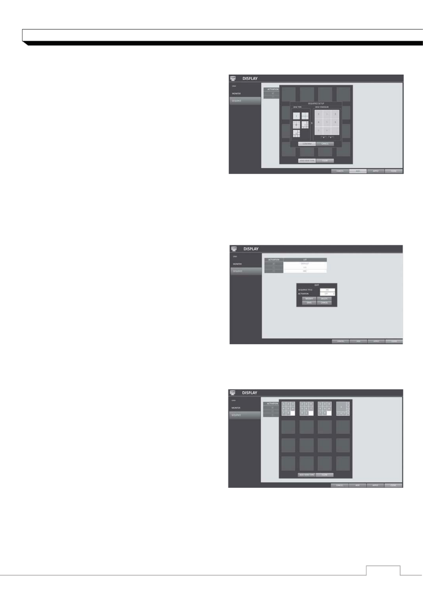
᧯᧮
System Setting
6. If the selected split mode is CONFIRMATION displayed on <VIEW >, select a channel you want
to display in each split screen.
7. Click <OK>.
The set sequence mode is confirmed and will be
added to the Add Sequence list in order
8. When done, click <CLOSE> in the bottom of the
screen.
After the sequence type is saved, you will return to
the previous screen.
9. Right-click on the new sequence, or press the
[ENTER] button on the remote control to edit or
delete it.
To edit a sequence
1. Select a sequence that you want to edit in the list.
2. The "EDIT" dialog appears.
3. Use the [ʆʈُٙ/ENTER] buttons on the remote
control or use the mouse to edit the selected
sequence.
>SEQUENCE TITLE : enter a new sequence name.
>ACTIVATION : specify the use of the sequence.
>MODIFY : change the settings of the sequence
mode.
>DELETE : delete the selected sequence list.
>CANCEL : cancel the changes.
4. Pressing the <EDIT> button will display the Edit Sequence window.
5. To change the existing settings, select a screen mode that you want to edit and right-click to
display the context menu. Then, select <EDIT>.
6. When done, click <CLOSE> to close the window.
7. To apply your changes, click <APPLY>.

᧯᧯
System Setting
Audio Setup
You can configure the settings of the voice and audio signal.
AUDIO
Choose whether to receive the live sound source
and select an audio channel.
1. From <SYSTEM SETUP> - <AUDIO>, select
<AUDIO>.
2. Use the [ʆʈُٙ/ENTER] buttons on the remote
control or use the mouse to select an item that
youwant to edit.
>DEFAULT LIVE AUDIO CHANNEL : select an
Audio channel to monitor on the live screen.
>NETWORK AUDIO TRANSMISSION : decide if
NVR transfers the audio signal to the remote client.
>RECEIVE NETWORK AUDIO : decide if NVR receives the audio signal from the remote client.
3. To apply the change, click <APPLY> in the bottom of the screen.
4. When done, press the [EXIT] button on the remote control or click <CLOSE> in the lower
screen. The confirmation message appears and you will return to the previous menu.
Buzzer output
You can set to output the buzzer if you manipulate
the remote control.
1. From <SYSTEM SETUP> - <AUDIO>, select
<BUZZER>.
2. Use the [ʆʈُٙ/ENTER] buttons on the remote
control or use the mouse to select an item that you
want to edit.
> REMOTE CONTROL : specify the output of a beep
when you press a button on the remote control.
3. To apply the change, click <APPLY> in the bottom
ofthe screen.
4. When done, press the [EXIT] button on the remote control or click <CLOSE> in the lower screen.
The confirmation message appears and you will return to the previous menu.
᧯᧰
System Setting
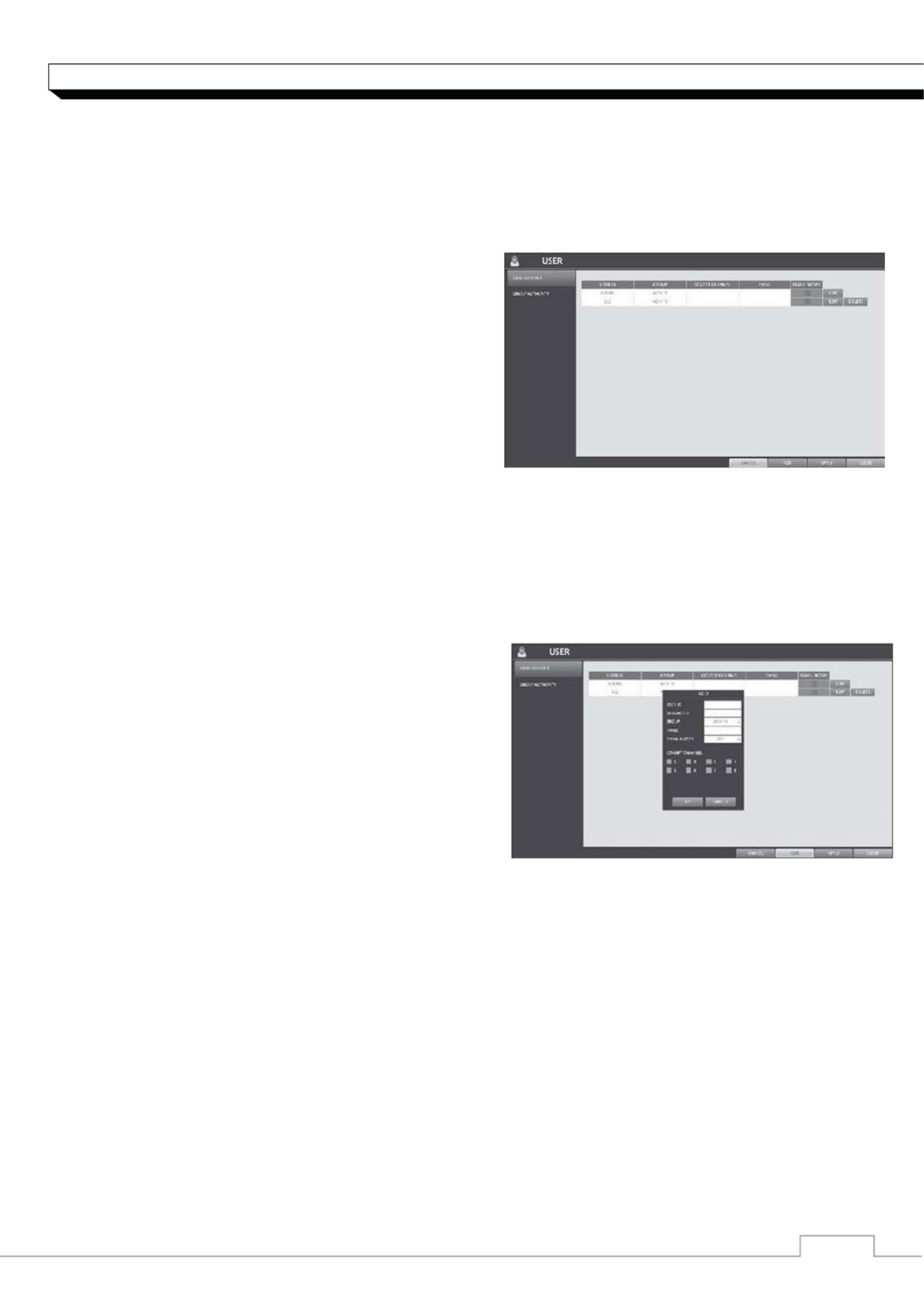
User Setting
You can configure the settings regarding user management and user and group permissions.
Management
You can add a user account(s) that can be edited at
a later time.
1. From <SYSTEM SETUP> - <USER>, select
<MANAGEMENT>.
2. Use the [ʆʈُٙ/ENTER] buttons on the remote
control or use the mouse to add a user account or
select an item that you want to edit.
3. To apply the change, click <APPLY> in the bottom
ofthe screen.
4. When done, press the [EXIT] button on the remote
control or click <CLOSE> in the lower screen. The confirmation message appears and you will
return to the previous menu.
To add a user account
1. Click <ADD> in the bottom of the screen.
2. Use the [ ]ʆʈُٙ buttons on the remote control and
move to a desired item. Then, press [ENTER] to
select the item.
> USER ID : enter the user ID using the virtual
keyboard.
> PASSWORD : With the virtual keyboard, enter the
password.
> GROUP : From <ADMIN>,<MANAGER> and
<USER>, select a group that the user belongs to.
> EMAIL : Type in the e-mail address to which you will receive notification of an event if it occurs.
> EMAIL NOTIFY : Choose whether you will receive notification of an event if it occurs.
> COVERT CHANNEL : You can set the channel to hide from a specific user.
3. When done, click <OK>.
The added user account will be listed.

᧯᧱
System Setting
To edit the user account information
1. From the list of users, select a user account to edit
and click <EDIT> next to it.
2. From the Edit window, make necessary changes
and click <OK>.
3. To delete the user account, click <DELETE>.
The <ADMIN> account can not be changed
or edited.
.
Group Authority
You can grant different user groups different permissions to a specific menu.
1. From <SYSTEM SETUP> - <USER>, select
<GROUP AUTHORITY>.
2. Use the [ʆʈُٙ/ENTER] buttons or use the
mouse to set the permissions for both
<MANAGER>and<USER> groups.
>SEARCH : Set the permissions for the
Search menu.
>ARCHIVING : Set the permissions for the Backup
menu.
>SYSTEM SETUP : Set the permissions for the
System Setup menu.
>RECORD SETUP : Set the Access Permissions for the Record Setup menu.
>EVENT ACTION CONTROL : Set the permissions to output the alarm or control the buzzer if an
event such as alarm occurs.
>LISTEN TO AUDIO : Set the permission to listen to the audio.
>MICROPHONE : Set the permission to speak through the microphone.
>REMOTE LOG IN : Set the permission to access remotely.
>SHUTDOWN : Set the permission to shut down NVR from the System menu.
3. To apply the change, click <APPLY> in the bottom of the screen.
4. When done, press the [EXIT] button on the remote control or click <CLOSE> in the lower
screen. The confirmation message appears and you will return to the previous menu.

᧯᧲
System Setting
Network Setup
You can configure the settings regarding user management and user and group permissions.
IP Setup
Specify the IP address as well as the remote service
port.
1. From <SYSTEM SETUP> - <NETWORK>,
select <IP SETUP>.
2. Use the [ʆʈ/ENTER] buttons on the remote
control or use the mouse to specify each item of the
network settings.
>DHCP : If it is checked, set the IP address of the
NVR to Dynamic IP.
- If the <DHCP> item is checked, the sub items
of IP address, gateway, subnet mask, primary DNS server, secondary DNS server will be filled
in automatically.
If you select to obtain an IP address from the <DHCP> server, when the lease time of the
DHCP server expires, you will lose connection to the IP camera momentarily while the network
settings will be updated. However, the network connection will be restored soon. It is
recommended to use a fixed IP for stable network connection.
>IP ADDRESS : Provide the IP address.
>GATEWAY : provide the gateway address.
>SUBNET MASK : provide the subnet mask address.
>1ST DNS SERVER : Enter the address of the primary DNS server.
>2ST DNS SERVER : Enter the address of the primary DNS server.
>RTSP SERVICE PORT : port number that the remote client receives the NVR video from.
>WEB SERVER PORT : port number used for connecting to the NVR with the web browser.
>PORT FORWARDING : If you are using a router, you can set the port forwarding so that external
access to the NVR is enabled.
If the router does not support the uPnP protocol, you must set the port forwarding manually.
For more information, contact your network administrator.
>DELETE PORT : release the port forwarding settings for the router.
>MAX TX SPEED : Limit the network transfer rate to access a remote client.
The video signal may be transferred at a less rate than specified, which depends on the status of
your network connection.
3. To apply the change, click <APPLY> in the bottom of the screen.
4. When done, press the [EXIT] button on the remote control or click <CLOSE> in the lower
screen. The confirmation message appears and you will return to the previous menu.
᧯᧴
System Setting
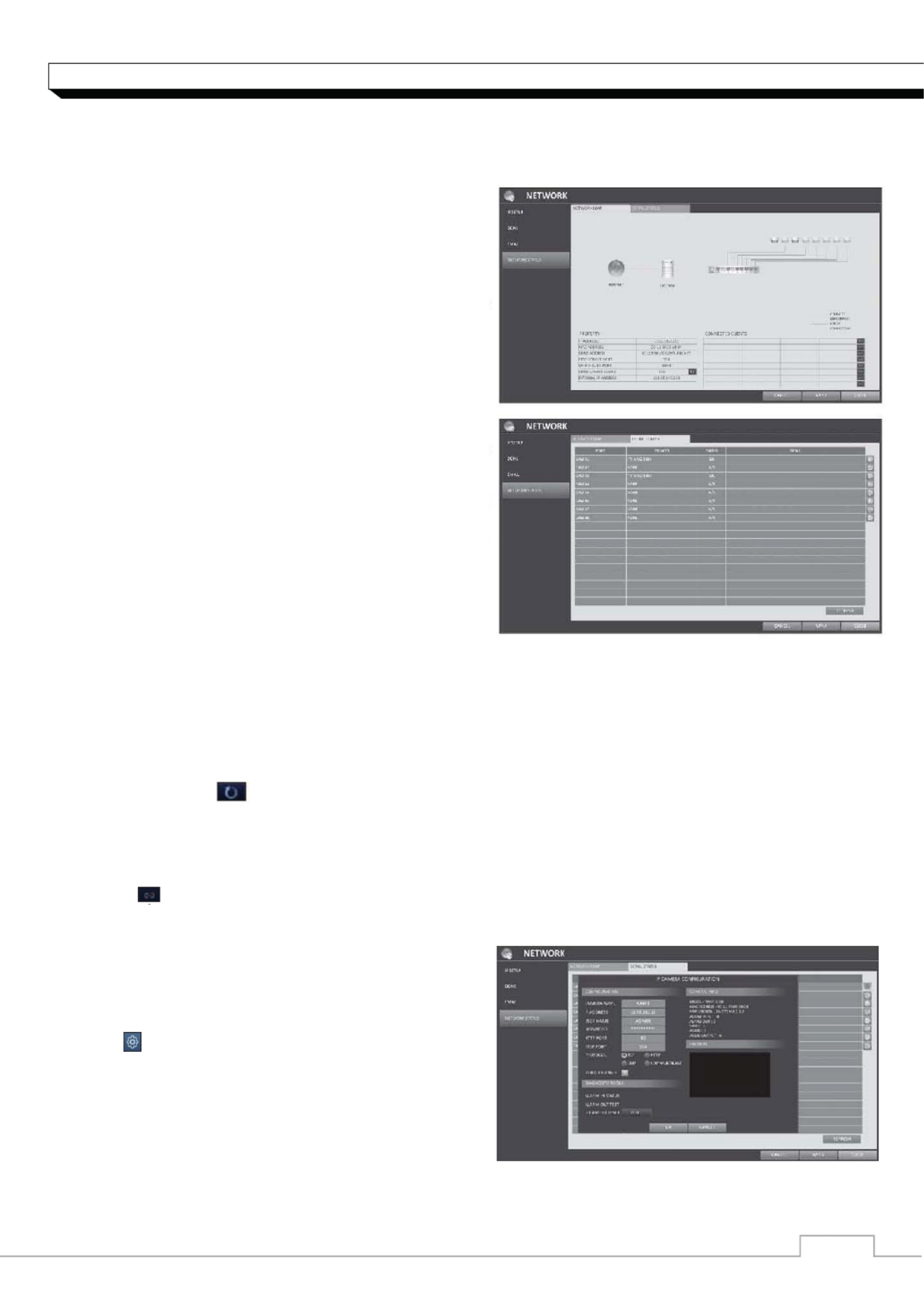
Network Status
From the network map screen, you can check the internet connection status and IP camera connecti
on status, and check also the details of the
connection status for each camera.
1. From <SYSTEM SETUP> - <NETWORK>,
select <NETWORK STATUS>.
2. Use the [ʆʈُٙ/ENTER] buttons on the remote
control or use the mouse to select one between
<NETWORK MAP> and <DETAIL STATUS>.
3. When done, press the [EXIT] button on the
remote control or click <CLOSE> in the lower
screen.
The confirmation message appears and you will
return to the previous menu.
Network Map
> IP ADDRRESS : Indicates the internal IP address
of the NVR.
> MAC ADDRESS: Indicates the internal MAC
address of the NVR.
>DDNS ADDRESS: Indicates the internal DDNS
address of the NVR.
>RTSP SERVICE PORT : Indicates the network
port of the video service.
For remote service, the router must have set up the port forwarding.
>WEB SERVICE PORT : Indicates the web service network port.
For the remote service to be enabled, the corresponding port of the router should have set
up the port forwarding.
>DDNS UPDATE STATUS : Shows if the DDNS address was registered to the DDNS server
normally. Press < > to try to register the DDNS address forcibly.
>EXTERNAL IP ADDRESS : Indicate the IP address for the internet, accessible from the NVR.
The NVR can be granted access with the web browser at http://<External IP Address>:<Web
Service Port>. The IP address can vary in a dynamic IP environment.
>CONNECTED CLIENTS :Shows the list of clients that are currently connected.
Press < > to terminate the connection of an unwanted client forcibly.
Termination is limited to only users in a lower group than the current user.
Detail Status
You can check the details of the cameras that are
connected to each channel.
Click < > in the right area of the list to show the
details. Click <RESET> in the “IP CAMERA
CONFIGURATION” window to reset the IP camera.
When the IP camera settings are complete,
click <OK>.

System Setting
System Setting
You can configure the settings of date/time, system management, and keyboard controller.
Date/Time
Specify the current date and time.
1. From <SYSTEM SETUP> - <SYSTEM>, select
<DATE/TIME>.
2. Use the [ʆʈ/ENTER] buttons on the remote
control or use the mouse to change the time or set
the options as necessary.
>DATE/TIME : Set the current time and date.
Click< > to adjust the time manually.
>DATE FORMAT : specify the date format.
>TIME FORMAT : specify the time format.
>TIME SERVER : obtain the current time from the
time server. Click < > to get the current time.
>AUTO TIME SYNC : automatically synchronize the
time with the time server at a specific time.
>SYNC AT : Set the time to sync with the time
server.
>TIMEZONE : specify the GMT standard time for
your local area.
>DST : You can set up or release the DST (Daylight
Saving Time).
3. To apply the change, click <APPLY> in the bottom of the screen.
4. When done, press the [EXIT] button on the remote control or click <CLOSE> in the lower
screen. The confirmation message appears and you will return to the previous menu.

System Setting
System Management
You can check, update or reset the system information.
1. From <SYSTEM SETUP> - <SYSTEM>, select
<SYSTEM MANAGEMENT>.
2. Use the [ʆʈ/ENTER] buttons on the remote
control or use the mouse to set each option of the
system management.
FW UPDATE : you can update the current
software with the latest version.
FACTORY DEFAULT : Return the NVR settings to
the factory default.
SYSTEM DATA : Save the system settings or get
the system information from other device.
- SAVE : Store the NVR settings to a storage device.
Connect the storage device to the USB port of NVR.
- LOAD : Apply the settings of the storage device
to the NVR. Connect the storage device to the
USB port of NVR.
PASSWORD : Open or close the dialog box for
settings of the menus: quit, system settings, record
settings, backup, and search.
If it is set to <Off>, note that the ADMIN account is
only effective and access to all menus will be
restricted.
EXPIRED TERM OF PASSWORD : You will be
prompted to change the current password after a
certain period of time.
AUTO LOGOUT : If there is no user input for a
certain period of time, you can set to log out
automatically.
WAIT TIME : Specify the waiting time for Auto
Logout.
AC POWER FREQUENCY : Select AC power
Frequency of your area.
60Hz : maximum frame rate will be set to 30fps
50Hz : maximum frame rate will be set to 25fps
If you have a flicker on the image, select suitable
the frequency.
3. When done, press the [EXIT] button on the
remote control or click <CLOSE> in the lower screen
to return to the previous menu.

System Setting
To perform the upgrade
1. Connect the USB storage device that contains the
updatable files.
2. Click <USB>.
3. Select one(s) from the updatable files LIST listed
in <F/W >.
4. Click <UPGRADE>.
5. When the confirmation message appears, click
<OK>.
6. The progress bar displays the progress of the
firmware upgrade process.
7. When the upgrade is complete, reboot the system.
System Setting
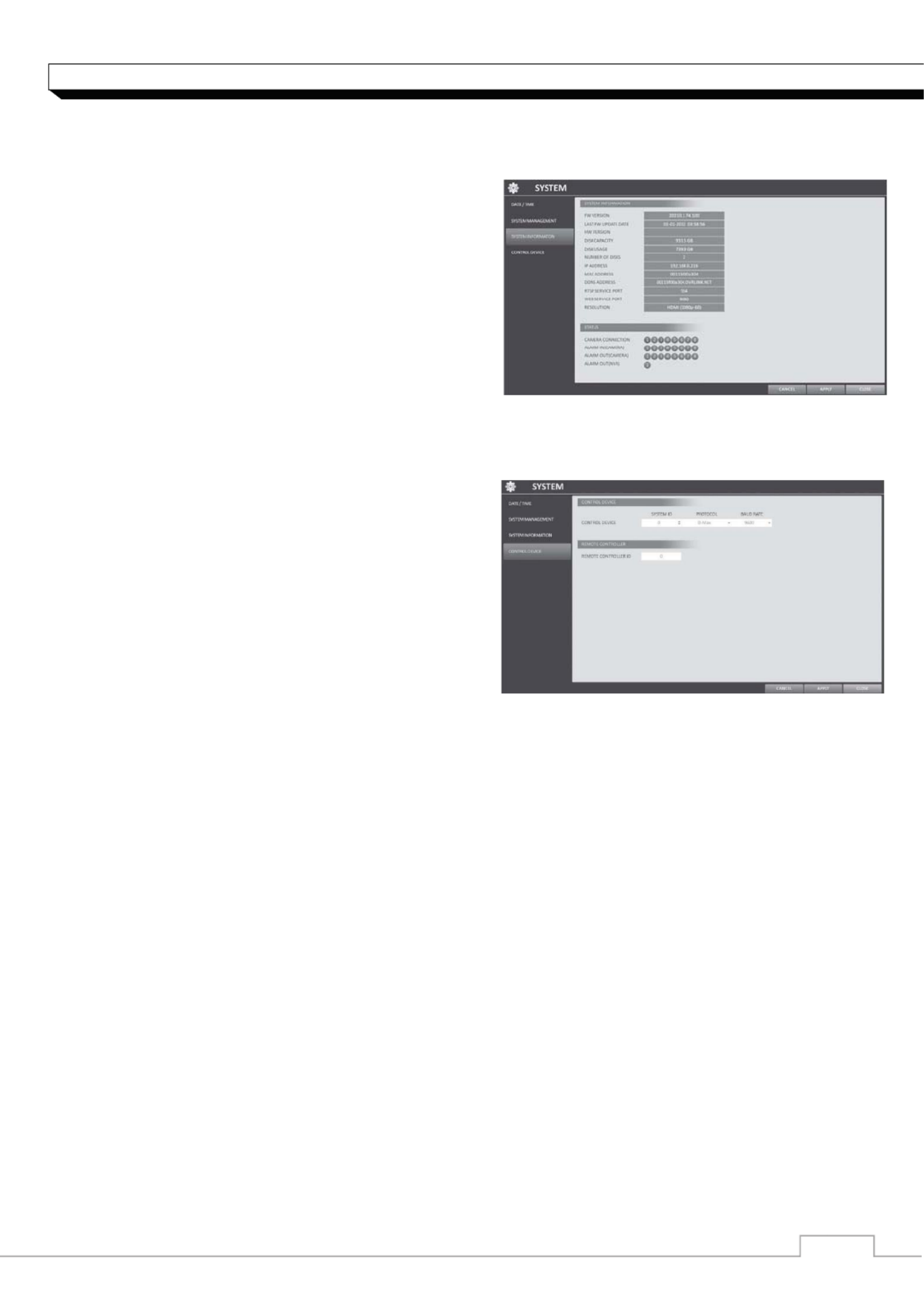
System Information
You can check the current system version and system-related settings.
1. From <SYSTEM SETUP> - <SYSTEM>, select
<SYSTEM INFORMATION>.
2. Check the status of the current system.
3. When done, press the [EXIT] button on the remote
control or click <CLOSE> in the lower screen.
The confirmation message appears and you will
return to the previous menu.
Control Device
Configure the settings of the remote control and
keyboard controller.
1. From <SYSTEM SETUP> - <SYSTEM>, select
<CONTROL DEVICE>.
2. Use the [ʆʈ/ENTER] buttons on the remote
control or use the mouse to set the connection
options for the control device.
>SYSTEM ID : Set the ID of the NVR so that the
keyboard controller can identify.
>PROTOCOL : Set up the protocol of the keyboard
controller.
>BAUD RATE : Specify the RS485 communication speed.
>REMOTE CONTROLLER ID : Set the ID of the remote control.
3. To apply the change, click <APPLY> in the bottom of the screen.
4. When done, press the [EXIT] button on the remote control or click <CLOSE> in the lower
screen. The confirmation message appears and you will return to the previous menu.

System Setting
Storage
You can configure the settings of and view information of the disk and external storage device.
Disk Information
It will show information about the connected disk.
1. From <SYSTEM SETUP> - <STORAGE>,
select <DISK INFORMATION>.
2. Use the [ʆʈ/ENTER] buttons on the remote
control or use the mouse to select either
<INTERNAL > or <EXTERNAL STORAGE>.
Please check the status for each connected device.
>START / END TIME : show the start time and end
time of data stored in each disk.
>STATUS : check if the connected disk is being
used by the NVR. If you encounter a problem with
the disk, the NVR will terminate the connection to
the disk and mark it as Not In Use.
>CAPACITY : show the capacity of the disk.
>MODEL : indicate the disk model.
>S.M.A.R.T STATUS : Read the S.M.A.R.T
information of the disk and check to display if the
current disk is in normal operation.
- NORMAL : The disk is in a normal state.
- CHECK : The disk has an error so that you need to check the disk or the connection cables of
the disk.
If you leave the problem unresolved, no recording may be enabled.
So it is recommended that you replace the disk immediately.
- ERROR : The disk fails or is unable to use due to an error of the disk or the cable.
The disk should be replaced immediately. Contact the retailer or the customer service to replace
the disk.
3. When done, press the [EXIT] button on the remote control or click <CLOSE> in the lower
screen to return to the previous menu.
System Setting
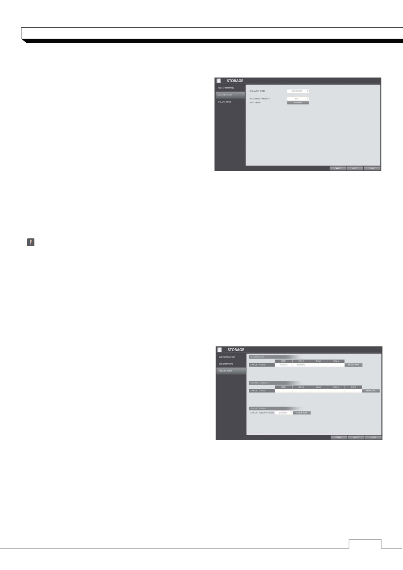
Disk Operations
You can set to delete the recording automatically and set the overwrite options, and you can also
format the HDD
recording data.
1. From <SYSTEM SETUP> - <STORAGE>,
select <DISK OPERATIONS>.
2. Use the [ʆʈ/ENTER] buttons on the remote
control or use the mouse to set the operation
conditions of the disk.
>DISK WRITE MODE
- If it is set to <OVERWRITE>, the existing data
will be overwritten by new recording data if the
recording data size exceeds the free space of the HDD.
- If the option is set to and the HDD is full, the NVR will stop recording and output the <ONCE>
beep or alarm that is pre-defined at <EVENT>.
>RECORDING TIME LIMIT : The recording data will be deleted after a specific time of
reservation. If it is set to <OFF>, this function will be disabled.
>DISK FORMAT : format the hard disk.
Note that formatting the HDD will delete all video data and logs.
3. To apply the change, click <APPLY> in the bottom of the screen.
4. When done, press the [EXIT] button on the remote control or click <CLOSE> in the lower
screen. The confirmation message appears and you will return to the previous menu.
S.M.A.R.T settings
You can check the S.M.A.R.T information of the disk and specify the check frequency.
9 What is S.M.A.R.T information?
9 S.M.A.R.T (Self-Monitoring, Analysis and Report Technology) is to detect a HDD that is likely to
cause a problem in the future with a warning message.
1. From <SYSTEM SETUP> - <STORAGE>,
select <S.M.A.R.T. SETUP>.
2. Use the [ʆʈ/ENTER] buttons on the remote
control or use the mouse to check the S.M.A.R.T
operation and specify the check interval.
>S.M.A.R.T STATUS : Read the S.M.A.R.T
information of the disk and check to display if the
current disk is in normal operation.
Click <DETAIL INFO> to view the details of the
remote control and keyboard controller.
- NORMAL : The disk is in a normal state.
- CHECK : The disk has an error so that you need to check the disk or the connection cables of
the disk. If you leave the problem unresolved, no recording may be enabled.
So it is recommended that you replace the disk immediately.
- ERROR : The disk fails or is unable to use due to an error of the disk or the cable. The disk
should be replaced immediately. Contact the retailer or the customer service to replace the disk.

System Setting
9 S.M.A.R.T CHECK INTERVAL : Specify the S.M.A.R.T check interval. Click <CHECK NOW>
to start checking.
3. To apply the change, click <APPLY> in the bottom of the screen.
4. When done, press the [EXIT] button on the remote control or click <CLOSE> in the lower
screen. The confirmation message appears and you will return to the previous menu.
Event Setup
Define various events, and specify the conditions to notify the user in various ways.
Alarm Out
Specify the alarm output conditions with the work schedule.
Alarm Out
1. From <SYSTEM SETUP> - <EVENT>, select
<ALARM OUT>.
2. Use the [ʆʈ/ENTER] buttons on the
remote control or use the mouse to select
<ALARM OUT>and configure the related settings.
>NAME : You can rename the alarm.
>OPERATION : Set the alarm output mode.
- N/O (Normal Open) : It normally stays Open.
However, if an event occurs, it will switch to Close.
- N/O (Normal Close) : It normally stays Close.
However, if an event occurs, it will switch to Open.
>DURATION : Specify the duration of the alarm output.
- TRANSPARENT : Keep the alarm out for as much time as the event lasts.
- UNTIL KEY : Keep the alarm out until a mouse or remote control button is pressed.
- 5 ~ 300 SEC : Keep the alarm out for as long as specified.
>TEST : Forcibly output the alarm for the test purpose.
3. To apply the change, click <APPLY> in the bottom of the screen.
4. When done, press the [EXIT] button on the remote control or click <CLOSE> in the lower
screen. The confirmation message appears and you will return to the previous menu.

System Setting
ON/OFF Schedule
You can activate or turn off the alarm output as
scheduled.
1. Use the buttons on the remote [ʆʈ/ENTER]
control or use the mouse to select a <DATE> for the
schedule.
2. Drag the mouse to resize the cell or use the on the
[ ]ʆʈ buttons to move to the cell, then press
[ENTER].
3. Select a desired alarm output mode.
>ON : The alarm output is always turned on.
>OFF : The alarm output is always turned off.
>EVENT : Trigger the alarm output in sync with the
event.
4. Click <COPY SCHEDULE> to check the checkbox
of the date that you want to copy the schedule at.
5. When done, click <OK> to apply the settings.
6. To apply the change, click <APPLY> in the bottom
of the screen.
7. When done, press the [EXIT] button on the remote
control or click <CLOSE> in the lower screen.
The confirmation message appears and you will return to the previous menu.
Event Notification
Specify the methods of notification such as buzzer, video popup or email if an event occurs.
1. From <SYSTEM SETUP> - <EVENT>, select <EVENT NOTIFICATION>.
2. Use the [ ]ʆʈ buttons on the remote control or use the mouse to select one from <BUZZER>,
<DISPLAY> and <EMAIL>.
3. Use the [ʆʈ/ENTER] buttons on the remote control or use the mouse to set the output
method and duration.
4. To apply the change, click <APPLY> in the bottom of the screen.
5. When done, press the [EXIT] button on the remote control or click <CLOSE> in the lower
screen. The confirmation message appears and you will return to the previous menu.
System Setting
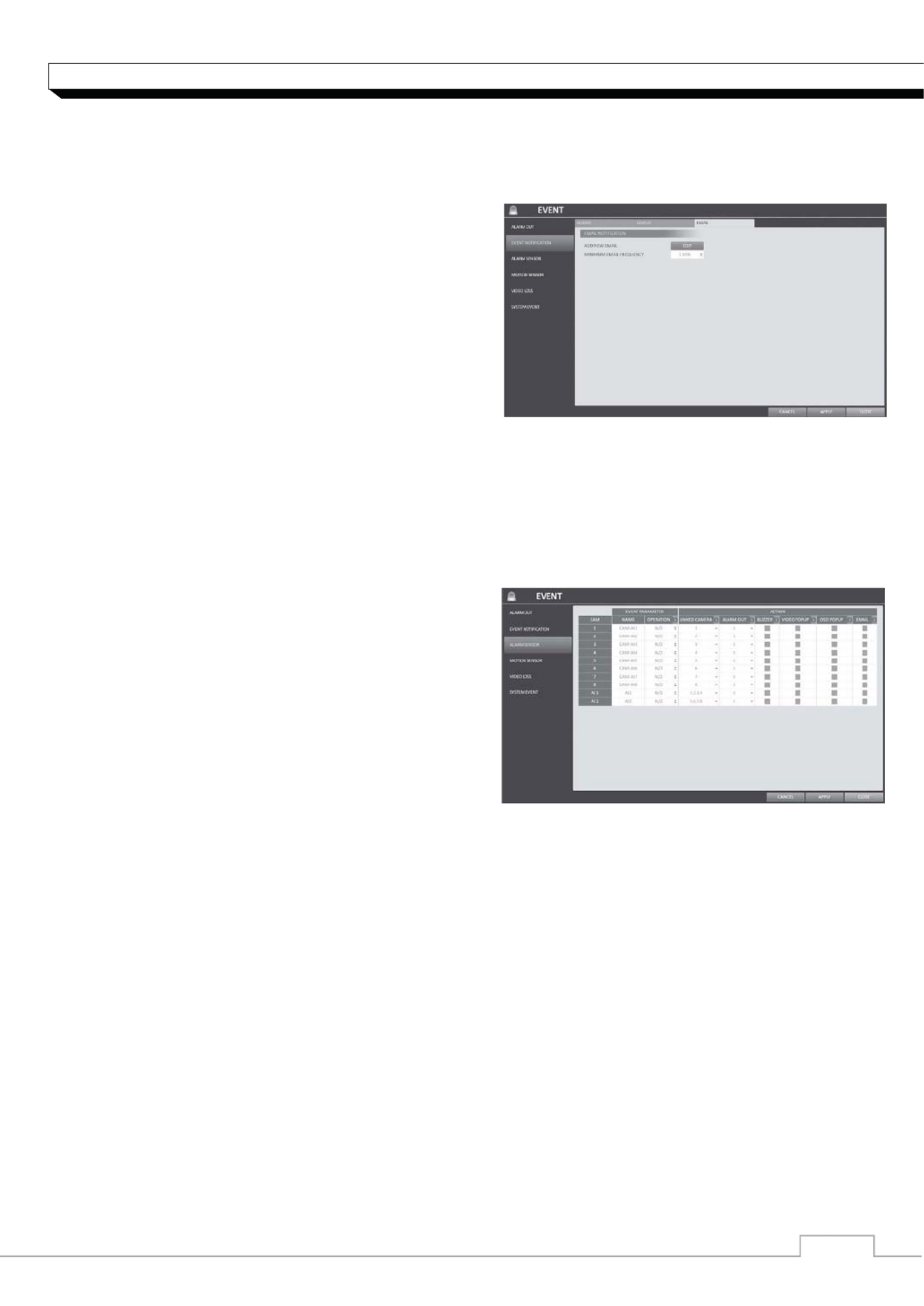
Email
If an event occurs, this will notify registered users of the event by email. If you do not want to receive
the email, uncheck the <EMAIL NOTIFY> option in <MANAGEMENT>. (Page 34)
>ADD NEW EMAIL
If you want to add a new mail recipient beside the
existing ones, click this to add the recipient.
>MINIMUM EMAIL FREQUENCY
Adjust the minimum frequency of sending the email.
For example, even if you have set the minimum
frequency to one minute and another event occurs
in less than one minute after the last email sending,
the email for the new event will be sent one minute
after.
Some email servers can block the email sending
if the email delivery cycle is too short, and
classify it as spam.
Contact your email service provider to adjust the minimum delivery cycle so that the server does
not classify the email as spam.
Alarm Sensor
You can configure the settings of the alarm sensor and specify the operation of the sensor if an
event occurs.
1. From <SYSTEM SETUP> - <EVENT>, select
<ALARM SENSOR>.
2. Use the [ ]ʆʈ buttons on the remote control or
use the mouse to specify the sensor input method
and operation.
>NAME : You can specify the name of the alarm
sensor.
>OPERATION : You can specify the type of the
alarm sensor.
- N/O (Normal Open) : Normally the sensor is left
Open. If the sensor switches to Close, an event will be triggered.
- N/C (Normal Close) : Normally the sensor is left Close. If the sensor switches to Open,
an event will be triggered.
>LINKED CAMERA : Set the camera to sync with the alarm sensor if it is triggered.
If you have set the alarm recording and the sensor detects the recording, all synchronized
cameras will start alarm recording.
>ALARM OUTPUT : Specify the alarm output channel if it is detected by the alarm sensor.
The alarm will be output to the specified channel.
>BUZZER : Specify the output of the buzzer if an alarm is detected by the alarm sensor.
>VIDEO POPUP : Select to display the video popup if an alarm is detected by the alarm sensor.
If there exist multiple <LINKED CAMERA>, the video popup will be displayed in the maximum
split mode.
>OSD POPUP : Select to display the OSD popup message if it is detected by the alarm sensor.
>EMAIL : Select to send an email if detected by the alarm sensor.
3. To apply the change, click <APPLY> in the bottom of the screen.
4. When done, press the [EXIT] button on the remote control or click <CLOSE> in the lower
screen. The confirmation message appears and you will return to the previous menu.
᧱᧭
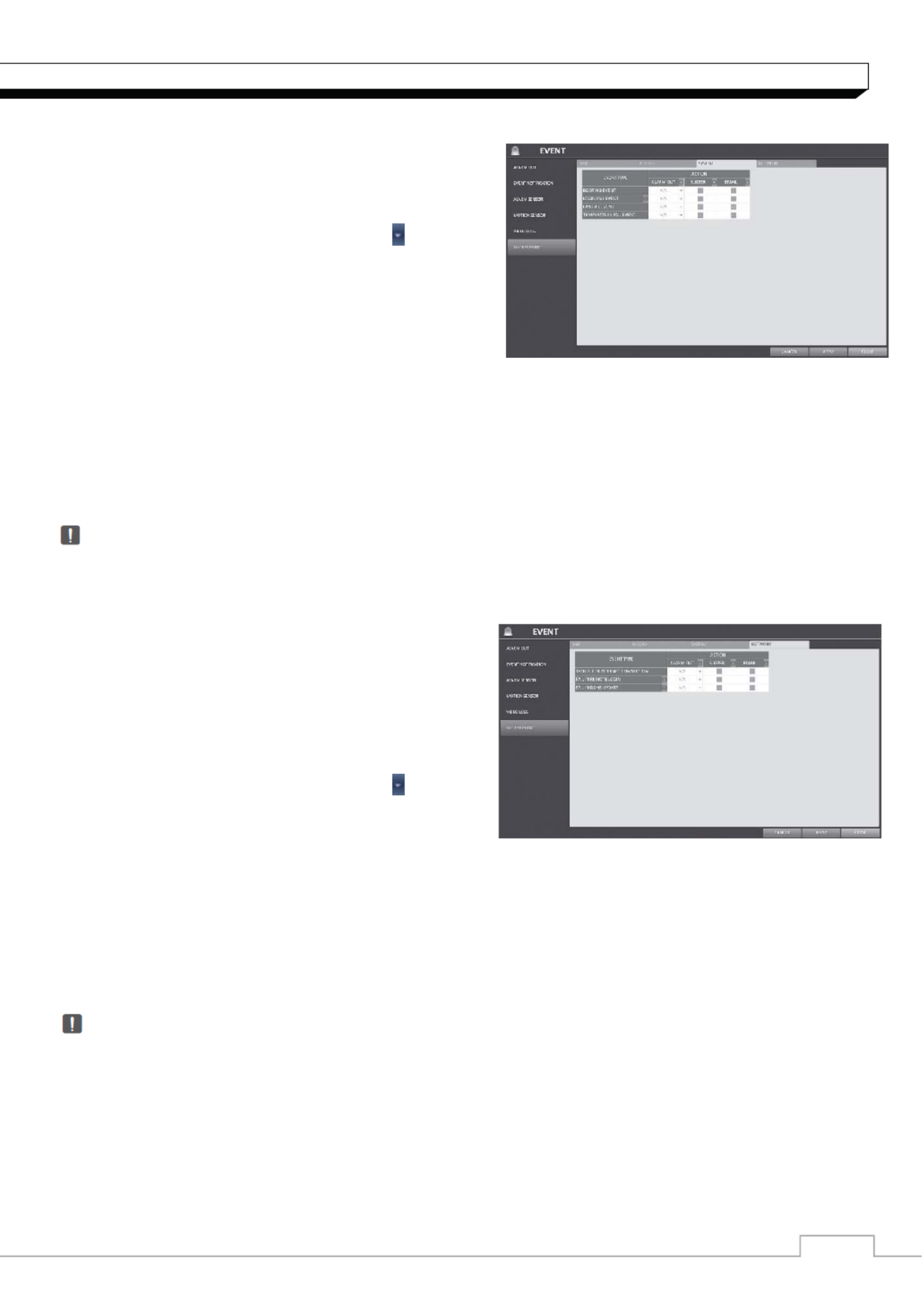
System Setting
System
>BOOTING EVENT: This event occurs when the
NVR is booting.
>LOGIN FAIL EVENT: This event occurs when the
NVR fails to log in.
You can specify the times of clicking < > to
trigger the event.
>FAN ERROR EVENT : This event occurs if the CPU
cooling fan or unit's cooling fan does not work at all.
If the fan fails, no recording will proceed by the NVR.
If you encounter a fan failure, contact the retailer or
the service enter for technical assistance.
>TEMPERATURE FAIL EVENT : This event occurs if the internal temperature of the NVR exceeds
the effective range. Then, the NVR will not operate normally. If this is the case, check the
followings and take a necessary measure.
- Check if the ventilation of the NVR is clogged with foreign substances. If so, remove them.
- Keep the NVR away from a heat source such as heater. Install it in a flat, lower area with good
ventilation.
- If the problem persists, contact the retailer or service center.
To monitor the normal operation of the NVR, it is recommended not to change the buzzer output
settings of the fan failure event and the temperature fail event.
Network
>TROUBLE IN INTERNET CONNECTION : Occurs
if the Internet connection to the NVR fails.
If you do not want to connect the NVR to the
network, leave the <Action> item blank.
>FAIL IN REMOTE LOGIN : This event occurs if a
remote client fails to log in due to an invalid ID or
password.
You can specify the times of clicking < > to
trigger the event.
>FAIL IN DDNS UPDATE : This event occurs if the
NVR tried to update the DDNS address but failed.
9 If the DDNS address fails to be updated,the NVR may not connect to a remote client.
If this is the case, enter the IP address from the client side to allow access from the NVR.
This is just a temporary measure.
For the IP address, move to and check <EXTERNAL IP ADDRESS> from the
<NETWORK> window. Note that the <EXTERNAL IP ADDRESS > is subject to change if
the NVR does not use the static IP.
Note that the <EXTERNAL IP ADDRESS> can change at any time in a dynamic IP
environment.
Produktspecifikationer
| Varumärke: | Ganz |
| Kategori: | övervakningskamera |
| Modell: | PixelMaster NR4HL |
Behöver du hjälp?
Om du behöver hjälp med Ganz PixelMaster NR4HL ställ en fråga nedan och andra användare kommer att svara dig
övervakningskamera Ganz Manualer

4 September 2024
4 September 2024
4 September 2024
4 September 2024
4 September 2024
2 September 2024
2 September 2024
2 September 2024
1 September 2024
1 September 2024
övervakningskamera Manualer
- övervakningskamera Sony
- övervakningskamera Samsung
- övervakningskamera Xiaomi
- övervakningskamera Bosch
- övervakningskamera Braun
- övervakningskamera Philips
- övervakningskamera Panasonic
- övervakningskamera Grundig
- övervakningskamera Gigaset
- övervakningskamera Honeywell
- övervakningskamera JVC
- övervakningskamera Motorola
- övervakningskamera Toshiba
- övervakningskamera VTech
- övervakningskamera Canon
- övervakningskamera Abus
- övervakningskamera Ag Neovo
- övervakningskamera Allnet
- övervakningskamera Alecto
- övervakningskamera Apc
- övervakningskamera Aldi
- övervakningskamera Aluratek
- övervakningskamera Airlive
- övervakningskamera Anker
- övervakningskamera Aritech
- övervakningskamera Acti
- övervakningskamera ACME
- övervakningskamera Edimax
- övervakningskamera Strong
- övervakningskamera Flamingo
- övervakningskamera Hikvision
- övervakningskamera Nedis
- övervakningskamera Thomson
- övervakningskamera Gembird
- övervakningskamera Yale
- övervakningskamera Pyle
- övervakningskamera Caliber
- övervakningskamera SereneLife
- övervakningskamera Eminent
- övervakningskamera Avanti
- övervakningskamera Renkforce
- övervakningskamera Kodak
- övervakningskamera Overmax
- övervakningskamera Niceboy
- övervakningskamera Sitecom
- övervakningskamera Blaupunkt
- övervakningskamera TP Link
- övervakningskamera Megasat
- övervakningskamera Logitech
- övervakningskamera Manhattan
- övervakningskamera Exibel
- övervakningskamera Ezviz
- övervakningskamera Trust
- övervakningskamera Fortinet
- övervakningskamera Elro
- övervakningskamera EMOS
- övervakningskamera Extech
- övervakningskamera KlikaanKlikuit
- övervakningskamera Denver
- övervakningskamera DataVideo
- övervakningskamera Schneider
- övervakningskamera Axis
- övervakningskamera Sanyo
- övervakningskamera Vitek
- övervakningskamera Imou
- övervakningskamera Hama
- övervakningskamera Maginon
- övervakningskamera Mitsubishi
- övervakningskamera Velleman
- övervakningskamera Smartwares
- övervakningskamera Profile
- övervakningskamera Marquant
- övervakningskamera Trebs
- övervakningskamera Ednet
- övervakningskamera Cisco
- övervakningskamera AVerMedia
- övervakningskamera Eufy
- övervakningskamera Steren
- övervakningskamera Perel
- övervakningskamera Engenius
- övervakningskamera Burg-Wachter
- övervakningskamera Lumens
- övervakningskamera Flir
- övervakningskamera Somfy
- övervakningskamera Netis
- övervakningskamera Genius
- övervakningskamera Adj
- övervakningskamera Digitus
- övervakningskamera Olympia
- övervakningskamera Belkin
- övervakningskamera Linksys
- övervakningskamera Buffalo
- övervakningskamera Uniden
- övervakningskamera Dahua Technology
- övervakningskamera Ion
- övervakningskamera GeoVision
- övervakningskamera Arlo
- övervakningskamera Netgear
- övervakningskamera Nest
- övervakningskamera LevelOne
- övervakningskamera DIO
- övervakningskamera Boss
- övervakningskamera Siedle
- övervakningskamera Ricoh
- övervakningskamera Hive
- övervakningskamera Netatmo
- övervakningskamera Marshall
- övervakningskamera Switel
- övervakningskamera Chacon
- övervakningskamera InFocus
- övervakningskamera Hombli
- övervakningskamera Reolink
- övervakningskamera First Alert
- övervakningskamera UniView
- övervakningskamera Planet
- övervakningskamera ZyXEL
- övervakningskamera Western Digital
- övervakningskamera Clas Ohlson
- övervakningskamera Naxa
- övervakningskamera Konig
- övervakningskamera Valueline
- övervakningskamera Trevi
- övervakningskamera Foscam
- övervakningskamera BRK
- övervakningskamera Orion
- övervakningskamera Zebra
- övervakningskamera EVE
- övervakningskamera Technaxx
- övervakningskamera D-Link
- övervakningskamera Waeco
- övervakningskamera Swann
- övervakningskamera Withings
- övervakningskamera Tenda
- övervakningskamera QSC
- övervakningskamera Xavax
- övervakningskamera Marmitek
- övervakningskamera Minox
- övervakningskamera Delta Dore
- övervakningskamera M-e
- övervakningskamera Lorex
- övervakningskamera Ubiquiti Networks
- övervakningskamera Marshall Electronics
- övervakningskamera Vaddio
- övervakningskamera Gira
- övervakningskamera Jung
- övervakningskamera Interlogix
- övervakningskamera Ring
- övervakningskamera Trendnet
- övervakningskamera DSC
- övervakningskamera Boyo
- övervakningskamera Laserliner
- övervakningskamera Iget
- övervakningskamera CRUX
- övervakningskamera Conceptronic
- övervakningskamera EverFocus
- övervakningskamera Adesso
- övervakningskamera Satel
- övervakningskamera Vivotek
- övervakningskamera Notifier
- övervakningskamera Lanberg
- övervakningskamera Friedland
- övervakningskamera Nexxt
- övervakningskamera Revo
- övervakningskamera Quantum
- övervakningskamera Monoprice
- övervakningskamera Broan
- övervakningskamera Avidsen
- övervakningskamera Furrion
- övervakningskamera Beafon
- övervakningskamera SPC
- övervakningskamera Stabo
- övervakningskamera Crestron
- övervakningskamera Chuango
- övervakningskamera ORNO
- övervakningskamera ETiger
- övervakningskamera INSTAR
- övervakningskamera Grandstream
- övervakningskamera Provision ISR
- övervakningskamera Monacor
- övervakningskamera Logilink
- övervakningskamera Aqara
- övervakningskamera Moxa
- övervakningskamera Advantech
- övervakningskamera Digital Watchdog
- övervakningskamera Ferguson
- övervakningskamera MEE Audio
- övervakningskamera Kwikset
- övervakningskamera Elmo
- övervakningskamera Intellinet
- övervakningskamera ClearOne
- övervakningskamera Ebode
- övervakningskamera Oplink
- övervakningskamera Kerbl
- övervakningskamera Dorr
- övervakningskamera Sonic Alert
- övervakningskamera Linear PRO Access
- övervakningskamera BirdDog
- övervakningskamera AVer
- övervakningskamera Summer Infant
- övervakningskamera SMC
- övervakningskamera Topica
- övervakningskamera Vimar
- övervakningskamera Kogan
- övervakningskamera Iiquu
- övervakningskamera Speco Technologies
- övervakningskamera Verint
- övervakningskamera ZKTeco
- övervakningskamera Brinno
- övervakningskamera Raymarine
- övervakningskamera Rostra
- övervakningskamera Caddx
- övervakningskamera Spyclops
- övervakningskamera Schwaiger
- övervakningskamera EKO
- övervakningskamera Inovonics
- övervakningskamera Kguard
- övervakningskamera Woonveilig
- övervakningskamera Mobi
- övervakningskamera V-Tac
- övervakningskamera Surveon
- övervakningskamera Hollyland
- övervakningskamera Epcom
- övervakningskamera EVOLVEO
- övervakningskamera Indexa
- övervakningskamera AViPAS
- övervakningskamera Kramer
- övervakningskamera Lutec
- övervakningskamera Whistler
- övervakningskamera Hanwha
- övervakningskamera ClearView
- övervakningskamera VideoComm
- övervakningskamera IMILAB
- övervakningskamera 3xLOGIC
- övervakningskamera Pelco
- övervakningskamera Leviton
- övervakningskamera EtiamPro
- övervakningskamera Inkovideo
- övervakningskamera Pentatech
- övervakningskamera Weldex
- övervakningskamera SecurityMan
- övervakningskamera Brilliant
- övervakningskamera Lindy
- övervakningskamera Canyon
- övervakningskamera CNB Technology
- övervakningskamera Tapo
- övervakningskamera Aigis
- övervakningskamera Exacq
- övervakningskamera Brickcom
- övervakningskamera Laxihub
- övervakningskamera Securetech
- övervakningskamera EFB Elektronik
- övervakningskamera Ernitec
- övervakningskamera NetMedia
- övervakningskamera Videotec
- övervakningskamera Illustra
- övervakningskamera Atlona
- övervakningskamera AVMATRIX
- övervakningskamera Nivian
- övervakningskamera Arenti
- övervakningskamera E-bench
- övervakningskamera Blow
- övervakningskamera Syscom
- övervakningskamera Tecno
- övervakningskamera Night Owl
- övervakningskamera Guardzilla
- övervakningskamera Astak
- övervakningskamera Blink
- övervakningskamera Milestone Systems
- övervakningskamera Zavio
- övervakningskamera Campark
- övervakningskamera IPX
- övervakningskamera Dedicated Micros
- övervakningskamera Hamlet
- övervakningskamera Equip
- övervakningskamera Annke
- övervakningskamera AVTech
- övervakningskamera Qoltec
- övervakningskamera Approx
- övervakningskamera Digimerge
- övervakningskamera Y-cam
- övervakningskamera Alfatron
- övervakningskamera Feelworld
- övervakningskamera KJB Security Products
- övervakningskamera Wisenet
- övervakningskamera BZBGear
- övervakningskamera WyreStorm
- övervakningskamera Infortrend
- övervakningskamera Epiphan
- övervakningskamera HiLook
- övervakningskamera Mach Power
- övervakningskamera Compro
- övervakningskamera Aida
- övervakningskamera Ikegami
- övervakningskamera Accsoon
- övervakningskamera Vimtag
- övervakningskamera Sonoff
- övervakningskamera Gewiss
- övervakningskamera Alula
- övervakningskamera Insteon
- övervakningskamera Costar
- övervakningskamera ALC
- övervakningskamera Security Labs
- övervakningskamera Comtrend
- övervakningskamera Seneca
- övervakningskamera Avigilon
- övervakningskamera American Dynamics
- övervakningskamera Vosker
- övervakningskamera Sentry360
- övervakningskamera Bea-fon
- övervakningskamera Owltron
- övervakningskamera Petcube
- övervakningskamera Enabot
- övervakningskamera Luis Energy
- övervakningskamera Sir Gawain
- övervakningskamera VisorTech
- övervakningskamera Atlantis Land
- övervakningskamera B & S Technology
- övervakningskamera I3International
- övervakningskamera IDIS
- övervakningskamera Promise Technology
- övervakningskamera Ecobee
- övervakningskamera Turing
- övervakningskamera Qian
- övervakningskamera Wasserstein
- övervakningskamera Qolsys
- övervakningskamera Control4
- övervakningskamera Milesight
- övervakningskamera GVI Security
- övervakningskamera Conbrov
- övervakningskamera HuddleCamHD
- övervakningskamera Setti+
- övervakningskamera Defender
- övervakningskamera Mobotix
- övervakningskamera IOIO
- övervakningskamera BIRDFY
- övervakningskamera I-PRO
- övervakningskamera DVDO
- övervakningskamera TCP
- övervakningskamera Bolin Technology
- övervakningskamera Nextech
Nyaste övervakningskamera Manualer
5 April 2025
5 April 2025
5 April 2025
28 Januari 2025

25 Januari 2025
25 Januari 2025

16 Januari 2025
10 Januari 2025
8 Januari 2025
8 Januari 2025