Gigabyte GA-M68MT-S2P Bruksanvisning
Läs nedan 📖 manual på svenska för Gigabyte GA-M68MT-S2P (88 sidor) i kategorin moderkort. Denna guide var användbar för 2 personer och betygsatt med 4.5 stjärnor i genomsnitt av 2 användare
Sida 1/88

GA-M68MT-S2P
AM3 socket motherboard for
AMD Phenom™ II processor/ AMD Athlon™ II processor
User's Manual
Rev. 1001
12ME-M68MT2P-1001R

Dec. 14, 2009
Motherboard
GA-M68MT-S2P
Motherboard
GA-M68MT-S2P
Dec. 14, 2009

Copyright
© 2010 GIGA-BYTE TECHNOLOGY CO., LTD. All rights reserved.
The trademarks mentioned in this manual are legally registered to their respective owners.
Disclaimer
Information in this manual is protected by copyright laws and is the property of GIGABYTE.
Changes to the specifications and features in this manual may be made by GIGABYTE
without prior notice. No part of this manual may be reproduced, copied, translated, transmitted,
or published in any form or by any means without GIGABYTE's prior written permission.
Documentation Classications
In order to assist in the use of this product, GIGABYTE provides the following types of documentations:
For detailed product information, carefully read the User's Manual.
For instructions on how to use GIGABYTE's unique features, read or download the information
on/from the Support&Downloads\Motherboard\Technology Guide page on our website.
For product-related information, check on our website at:
http://www.gigabyte.com.tw
Identifying Your Motherboard Revision
The revision number on your motherboard looks like this: "REV: X.X." For example, "REV: 1.0"
means the revision of the motherboard is 1.0. Check your motherboard revision before updating
motherboard BIOS, drivers, or when looking for technical information.
Example:

- 4 -
Table of Contents
Box Contents ...................................................................................................................6
Optional Items .................................................................................................................6
GA-M68MT-S2P Motherboard Layout .............................................................................7
GA-M68MT-S2P Motherboard Block Diagram ................................................................8
Chapter 1 Hardware Installation .....................................................................................9
1-1 Installation Precautions .................................................................................... 9
1-2 ProductSpecications .................................................................................... 10
1-3 Installing the CPU and CPU Cooler ............................................................... 13
1-3-1 Installing the CPU ...................................................................................................13
1-3-2 Installing the CPU Cooler .......................................................................................15
1-4 Installing the Memory ..................................................................................... 16
1-4-1 DualChannelMemoryConguration .....................................................................16
1-4-2 Installing a Memory ...............................................................................................17
1-5 Installing an Expansion Card ......................................................................... 18
1-6 Back Panel Connectors .................................................................................. 19
1-7 Internal Connectors ........................................................................................ 21
Chapter 2 BIOS Setup ..................................................................................................29
2-1 Startup Screen ............................................................................................... 30
2-2 The Main Menu .............................................................................................. 31
2-3 MB Intelligent Tweaker(M.I.T.) ........................................................................ 33
2-4 Standard CMOS Features .............................................................................. 36
2-5 Advanced BIOS Features .............................................................................. 38
2-6 Integrated Peripherals .................................................................................... 40
2-7 Power Management Setup ............................................................................. 43
2-8 PnP/PCICongurations ................................................................................. 45
2-9 PC Health Status ............................................................................................ 46
2-10 Load Fail-Safe Defaults .................................................................................. 48
2-11 Load Optimized Defaults ................................................................................ 48
2-12 Set Supervisor/User Password ...................................................................... 49
2-13 Save & Exit Setup .......................................................................................... 50
2-14 Exit Without Saving ........................................................................................ 50

- 5 -
Chapter 3 Drivers Installation ........................................................................................51
3-1 Installing Chipset Drivers ............................................................................... 51
3-2 Application Software ...................................................................................... 52
3-3 Technical Manuals .......................................................................................... 52
3-4 Contact ........................................................................................................... 53
3-5 System ........................................................................................................... 53
3-6 Download Center ........................................................................................... 54
Chapter 4 Unique Features ...........................................................................................55
4-1 Xpress Recovery2 .......................................................................................... 55
4-2 BIOS Update Utilities ..................................................................................... 58
4-2-1 Updating the BIOS with the Q-Flash Utility .............................................................58
4-2-2 Updating the BIOS with the @BIOS Utility .............................................................61
4-3 EasyTune 6 .................................................................................................... 62
Chapter 5 Appendix ......................................................................................................63
5-1 ConguringSATAHardDrive(s) ..................................................................... 63
5-1-1 ConguringtheOnboardSATAController ..............................................................63
5-1-2 Making a SATA RAID Driver Diskette .....................................................................68
5-1-3 Installing the SATA RAID Driver and Operating System .........................................69
5-2 ConguringAudioInputandOutput ............................................................... 73
5-2-1 Conguring2/4/5.1/7.1-ChannelAudio ...................................................................73
5-2-2 ConguringS/PDIFIn/Out ......................................................................................76
5-2-3 ConguringMicrophoneRecording ........................................................................78
5-2-4 Using the Sound Recorder .....................................................................................80
5-3 Troubleshooting.............................................................................................. 81
5-3-1 Frequently Asked Questions ..................................................................................81
5-3-2 Troubleshooting Procedure ....................................................................................82
5-4 Regulatory Statements ................................................................................... 84
- 6 -
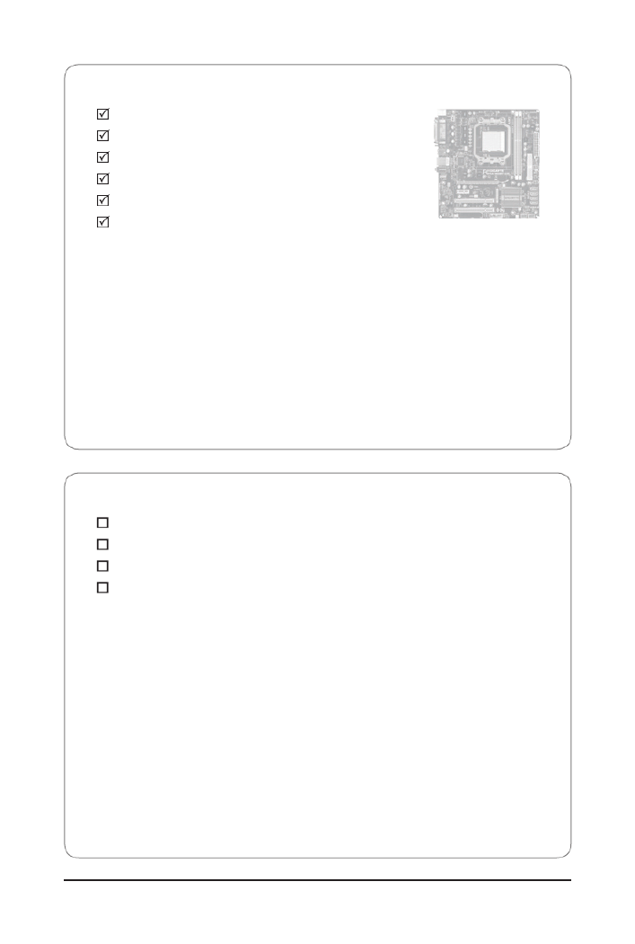
Box Contents
GA-M68MT-S2P
Motherboard driver disk
User's Manual
One IDE cable
One SATA cable
I/O Shield
Optional Items
Floppy disk drive cable (Part No. 12CF1-1FD001-7*R)
2-port USB 2.0 bracket (Part No. 12CR1-1UB030-5*R)
2-port SATA power cable (Part No. 12CF1-2SERPW-0*R)
S/PDIF In and Out cable (Part No. 12CR1-1SPINO-1*R)
• The box contents above are for reference only and the actual items shall depend on the product package you obtain.
The box contents are subject to change without notice.
• The motherboard image is for reference only.

- 7 -
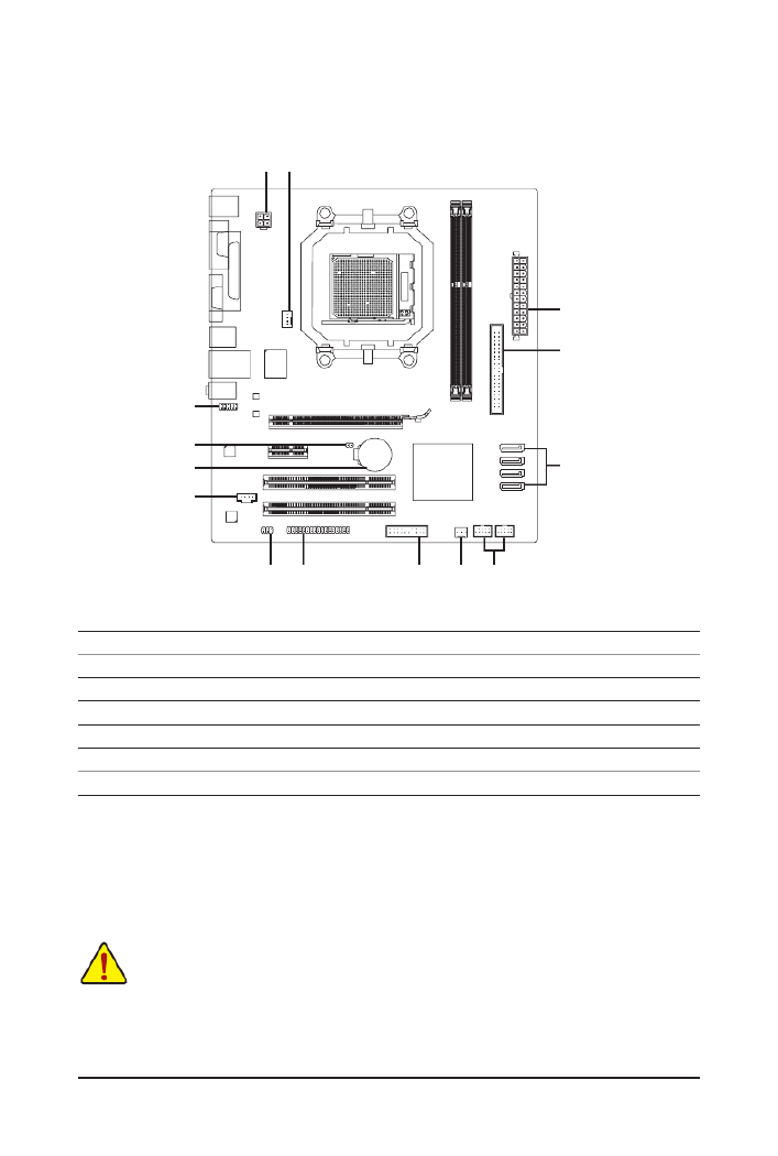
GA-M68MT-S2P Motherboard Layout
KB_MS
CPU_FAN
Socket AM3 ATX
GA-M68MT-S2P
CD_IN
F_AUDIO
AUDIO
PCIEX16
IDE
DDR3_1
DDR3_2
ATX_12V
NVIDIA® GeForce
7025/nForce 630a
SATA2_2
SATA2_3
SATA2_1
SATA2_0
PCI1
COMA
CODEC
BAT
VGA
USB
LAN
PCI2
F_USB1
M_BIOS
FDD F_PANEL
B_BIOS
F_USB2
PCIEX1
R_USB
CLR_CMOS
SPDIF_IO
LPT
SYS_FAN
Realtek
RTL8211CL
iTE
IT8720
- 8 -
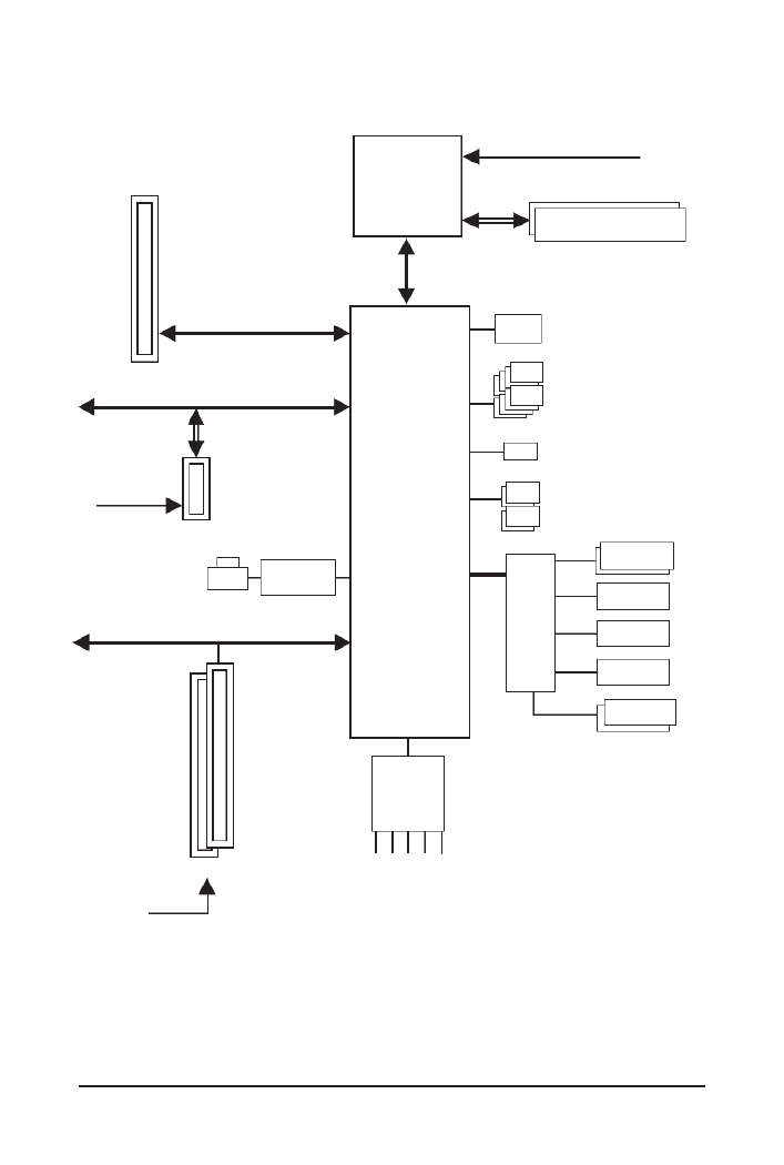
GA-M68MT-S2P Motherboard Block Diagram
AM3 CPU
Hyper Transport Bus
NVIDIA
®
GeForce
7025/nForce 630a
2 PCI
PCI Bus
PCI CLK
(33 MHz)
PCIe CLK
(100 MHz)
PCI Express Bus
iTE
IT8720
Floppy
CPU CLK+/- (200 MHz)
ATA-133/100/66/33 IDE Channel
Dual BIOS
COM Port
LPC
Bus
1 PCI Express x1
PCIe CLK
(100 MHz)
1 PCI Express x16
4 SATA 3Gb/s
LAN RJ45
x1
PCI Express x16
PS/2 KB/Mouse
8 USB 2.0/1.1
Line Out
MIC
Line In
S/PDIF In
S/PDIF Out
CODEC
1 D-Sub
Realtek
RTL8211CL
LPT Port
Dual Channel Memory
DDR3 1666(O.C.)/1066/800 MHz

- 9 - Hardware Installation
1-1 Installation Precautions
The motherboard contains numerous delicate electronic circuits and components which can
become damaged as a result of electrostatic discharge (ESD). Prior to installation, carefully read
the user's manual and follow these procedures:
Prior to installation, do not remove or break motherboard S/N (Serial Number) sticker or •
warranty sticker provided by your dealer. These stickers are required for warranty validation.
Always remove the AC power by unplugging the power cord from the power outlet before •
installing or removing the motherboard or other hardware components.
When connecting hardware components to the internal connectors on the motherboard, •
make sure they are connected tightly and securely.
When handling the motherboard, avoid touching any metal leads or connectors.•
It is best to wear an electrostatic discharge (ESD) wrist strap when handling electronic com-•
ponents such as a motherboard, CPU or memory. If you do not have an ESD wrist strap,
keepyourhandsdryandrsttouchametalobjecttoeliminatestaticelectricity.
•
Prior to installing the motherboard, please have it on top of an antistatic pad or within an
electrostatic shielding container.
Before unplugging the power supply cable from the motherboard, make sure the power sup-•
ply has been turned off.
Before turning on the power, make sure the power supply voltage has been set according to •
the local voltage standard.
Before using the product, please verify that all cables and power connectors of your hard-•
ware components are connected.
To prevent damage to the motherboard, do not allow screws to come in contact with the •
motherboard circuit or its components.
Make sure there are no leftover screws or metal components placed on the motherboard or •
within the computer casing.
Do not place the computer system on an uneven surface•
.
Do not place the computer system in a high-temperature environment.•
Turning on the computer power during the installation process can lead to damage to sys-•
tem components as well as physical harm to the user.
If you are uncertain about any installation steps or have a problem related to the use of the •
product,pleaseconsultacertiedcomputertechnician.
Chapter 1 Hardware Installation

- 11 - Hardware Installation
Internal 1 x 24-pin ATX main power connector
Connectors 1 x 4-pin ATX 12V power connector
1xoppydiskdriveconnector
1 x IDE connector
4 x SATA 3Gb/s connectors
1 x CPU fan header
1 x system fan header
1 x front panel header
1 x front panel audio header
1 x CD In connector
1 x S/PDIF In/Out header
2 x USB 2.0/1.1 headers
1 x clearing CMOS jumper
Back Panel 1 x PS/2 keyboard port
Connectors 1 x PS/2 mouse port
1 x D-Sub port
1 x parallel port
1 x serial port
4 x USB 2.0/1.1 ports
1 x RJ-45 port
3 x audio jacks (Line In/Line Out/Microphone)
I/O Controller iTE IT8720 chip
Hardware Monitor
System voltage detection
CPU/System temperature detection
CPU/System fan speed detection
CPU/System overheating warning
CPU/System fan fail warning
CPU fan speed control
(Note 3)
BIOS 2x8Mbitash
Use of licensed AWARD BIOS
Support for DualBIOS
™
PnP 1.0a, DMI 2.0, SM BIOS 2.4, ACPI 1.0b

Hardware Installation - 12 -
(Note 1) Due to Windows 32-bit operating system limitation, when more than 4 GB of physical memory is
installed, the actual memory size displayed will be less than 4 GB.
(Note2) To congure7.1-channel audio,youhaveto usean HDfrontpanel audiomoduleand enablethe
multi-channel audio feature through the audio driver.
(Note 3) Whether the CPU fan speed control function is supported will depend on the CPU cooler you install.
(Note 4) Available functions in EasyTune may differ by motherboard model.
Unique Features Support for @BIOS
Support for Q-Flash
Support for Xpress BIOS Rescue
Support for Download Center
Support for Xpress Install
Support for Xpress Recovery2
Support for EasyTune
(Note 4)
Bundled Software
Norton Internet Security (OEM version)
Operating System
Support for Microsoft
®
Windows
®
7/Vista/XP
Form Factor Micro ATX Form Factor; 24.4cm x 22.5cm

- 13 - Hardware Installation
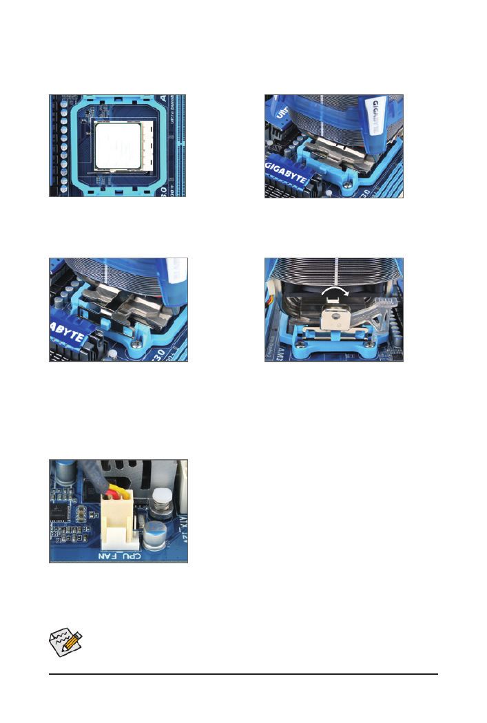
1-3 Installing the CPU and CPU Cooler
1-3-1 Installing the CPU
A. Locate the pin one (denoted by a small triangle) of the CPU socket and the CPU.
Read the following guidelines before you begin to install the CPU:
• Make sure that the motherboard supports the CPU.
(Go to GIGABYTE's website for the latest CPU support list.)
• Always turn off the computer and unplug the power cord from the power outlet before installing
the CPU to prevent hardware damage.
• Locate the pin one of the CPU. The CPU cannot be inserted if oriented incorrectly. (Or you may
locate the notches on both sides of the CPU and alignment keys on the CPU socket.)
• Apply an even and thin layer of thermal grease on the surface of the CPU.
• Do not turn on the computer if the CPU cooler is not installed, otherwise overheating and dam-
age of the CPU may occur.
• SettheCPUhostfrequencyinaccordancewiththeCPUspecications.Itisnotrecommended
thatthesystembusfrequencybesetbeyondhardwarespecicationssinceitdoesnotmeetthe
standard requirements for the peripherals. If you wish to set the frequency beyond the standard
specications,pleasedosoaccordingtoyourhardwarespecicationsincludingtheCPU,graph-
ics card, memory, hard drive, etc.
AM3 CPU
AM3 Socket
A Small Triangle Marking
Denotes CPU Pin One
A Small Triangle Mark
Denotes Pin One of the
Socket

Hardware Installation - 14 -
B. Follow the steps below to correctly install the CPU into the motherboard CPU socket.
• Before installing the CPU, make sure to turn off the computer and unplug the power cord from the
power outlet to prevent damage to the CPU.
• DonotforcetheCPUintotheCPUsocket.TheCPUcannottiniforientedincorrectly.Adjustthe
CPU orientation if this occurs.
Step 1:
Completely lift up the CPU socket locking lever.
Step 2:
Align the CPU pin one (small triangle marking) with the triangle mark
on the CPU socket and gently insert the CPU into the socket. Make
surethattheCPUpinstperfectlyintotheirholes.OncetheCPUis
positionedintoitssocket,placeonengerdownonthemiddleofthe
CPU, lowering the locking lever and latching it into the fully locked
position.
CPU Socket
Locking Lever
- 15 - Hardware Installation
Use extreme care when removing the CPU cooler because the thermal grease/tape between the
CPU cooler and CPU may adhere to the CPU. Inadequately removing the CPU cooler may damage
the CPU.
1-3-2 Installing the CPU Cooler
Follow the steps below to correctly install the CPU cooler on the CPU. (The following procedure uses the
GIGABYTE cooler as the example.)
Step 1:
Apply an even and thin layer of thermal grease
on the surface of the installed CPU.
Step 2:
Place the CPU cooler on the CPU.
Step 3:
Hook the CPU cooler clip to the mounting lug
on one side of the retention frame. On the other
side,push straight down on the the CPU cooler
clip to hook it to the mounting lug on the reten-
tion frame.
Step 4:
Turn the cam handle from the left side to the
right side (as the picture above shows) to lock
into place. (Refer to your CPU cooler installation
manual for instructions on installing the cooler.)
Step 5:
Finally, attach the power connector of the CPU cooler to the CPU
fan header (CPU_FAN) on the motherboard.
Hardware Installation - 16 -
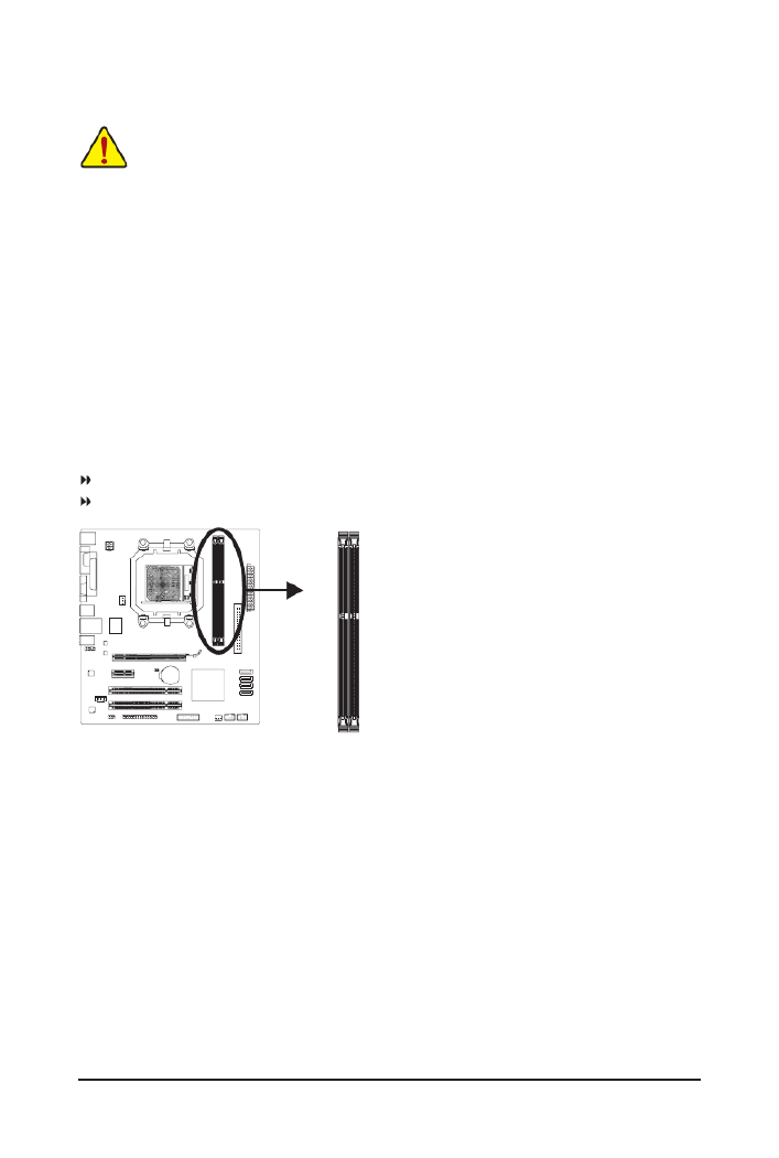
1-4 Installing the Memory
Due to CPU limitation, read the following guidelines before installing the memory in Dual Channel mode.
1. Dual Channel mode cannot be enabled if only one DDR3 memory module is installed.
2. When enabling Dual Channel mode with two memory modules, it is recommended that memory of
the same capacity, brand, speed, and chips be used.
Read the following guidelines before you begin to install the memory:
• Make sure that the motherboard supports the memory. It is recommended that memory of the
same capacity, brand, speed, and chips be used.
(Go to GIGABYTE's website for the latest supported memory speeds and memory modules.)
• Always turn off the computer and unplug the power cord from the power outlet before installing
the memory to prevent hardware damage.
• Memory modules have a foolproof design. A memory module can be installed in only one direc-
tion. If you are unable to insert the memory, switch the direction.
1-4-1 Dual Channel Memory Conguration
This motherboard provides two DDR3 memory sockets and supports Dual Channel Technology. After the
memory is installed, theBIOS willautomatically detect thespecications and capacityof the memory. En-
abling Dual Channel memory mode will double the original memory bandwidth.
The two DDR3 memory sockets are divided into two channels and each channel has two memory sockets as
following:
Channel 0: DDR3_1
Channel 1: DDR3_2
DDR3_1
DDR3_2

- 17 - Hardware Installation
1-4-2 Installing a Memory
Notch
ADDR3memorymodulehasanotch,soitcanonlytinonedirection.Followthestepsbelowtocorre
install your memory modules in the memory sockets.
DDR3 DIMM
Step 1:
Note the orientation of the memory module. Spread the retaining
clips at both ends of the memory socket. Place the memory module
onthesocket.Asindicatedinthepictureontheleft,placeyourn-
gers on the top edge of the memory, push down on the memory and
insert it vertically into the memory socket.
Step 2:
The clips at both ends of the socket will snap into place when the
memory module is securely inserted.
Before installing a memory module, make sure to turn off the computer and unplug the power
cord from the power outlet to prevent damage to the memory module.
DDR3 and DDR2 DIMMs are not compatible to each other or DDR DIMMs. Be sure to install
DDR3 DIMMs on this motherboard.

Hardware Installation - 18 -
1-5 Installing an Expansion Card
Read the following guidelines before you begin to install an expansion card:
• Make sure the motherboard supports the expansion card. Carefully read the manual that came
with your expansion card.
• Always turn off the computer and unplug the power cord from the power outlet before installing
an expansion card to prevent hardware damage.
PCI Slot
PCI Express p18-x1 Slot
PCI Express x16 Slot
Follow the steps below to correctly install your expansion card in the expansion slot.
1. Locate an expansion slot that supports your card. Remove the metal slot cover from the chassis back panel.
2. Align the card with the slot, and press down on the card until it is fully seated in the slot.
3. Make sure the metal contacts on the card are completely inserted into the slot.
4. Secure the card’s metal bracket to the chassis back panel with a screw.
5. After installing all expansion cards, replace the chassis cover(s).
6. Turn on your computer. If necessary, go to BIOS Setup to make any required BIOS changes for your
expansion card(s).
7. Install the driver provided with the expansion card in your operating system.
Example: Installing and Removing a PCI Express Graphics Card:
• Installing a Graphics Card:
Gently push down on the top edge of the card until
it is fully inserted into the PCI Express slot. Make
sure the card is securely seated in the slot and
does not rock.
• Removing the Card:
Gently push back on the lever on the slot and then lift the card straight out from
the slot.

- 19 - Hardware Installation
1-6 Back Panel Connectors
PS/2 Keyboard and PS/2 Mouse Port
Use the upper port (green) to connect a PS/2 mouse and the lower port (purple) to connect a PS/2 keyboard.
Parallel Port
Use the parallel port to connect devices such as a printer, scanner and etc. The parallel port is also
called a printer port.
Serial Port
Use the serial port to connect devices such as a mouse, modem or other peripherals.
D-Sub Port
The D-Sub port supports a 15-pin D-Sub connector. Connect a monitor that supports D-Sub connection
to this port.
USB 2.0/1.1 Port
TheUSBportsupportstheUSB2.0/1.1specication.UsethisportforUSBdevicessuchasaUSBke
board/mouse,USBprinter,USBashdriveandetc.
RJ-45 LAN Port
The Gigabit Ethernet LAN port provides Internet connection at up to 1 Gbps data rate. The following de-
scribes the states of the LAN port LEDs.
Activity LED:
State Description
Blinking Data transmission or receiving is occurring
Off No data transmission or receiving is occurring
Connection/Speed LED:
State Description
Orange 1 Gbps data rate
Green 100 Mbps data rate
Off 10 Mbps data rate
Activity LED
Connection/
Speed LED
LAN Port

Hardware Installation - 20 -
• When removing the cable connected to a back panel connector, rst remove the cable from
your device and then remove it from the motherboard.
• When removing the cable, pull it straight out from the connector. Do not rock it side to side to
prevent an electrical short inside the cable connector.
To congure 7.1-channel audio, you have to use an HD front panel audio module and enable
the multi-channel audio feature through the audio driver. Refer to the instructions on setting up a
2/4/5.1/7.1-channelaudiocongurationinChapter5,"Conguring2/4/5.1/7.1-ChannelAudio."
Line In Jack (Blue)
The default line in jack. Use this audio jack for line in devices such as an optical drive, walkman, etc.
Line Out Jack (Front Speaker Out, Green)
The default line out jack. Use this audio jack for a headphone or 2-channel speaker. This jack can be
usedtoconnectfrontspeakersina4/5.1-channelaudioconguration.
Mic In Jack (Pink)
The default Mic in jack. Microphones must be connected to this jack.
- 21 - Hardware Installation
1-7 Internal Connectors
Read the following guidelines before connecting external devices:
• First make sure your devices are compliant with the connectors you wish to connect.
• Before installing the devices, be sure to turn off the devices and your computer. Unplug the
power cord from the power outlet to prevent damage to the devices.
• After installing the device and before turning on the computer, make sure the device cable has
been securely attached to the connector on the motherboard.
1) ATX_12V
2) ATX
3) CPU_FAN
4) SYS_FAN
5) FDD
6) IDE
7) SATA2_0/1/2/3
8) F_PANEL
9) F_AUDIO
10) CD_IN
11) SPDIF_IO
12) F_USB1/F_USB2
13) CLR_CMOS
14) BAT
1
9
10
5 8 12
7
6
2
11
14
13
3
4

Hardware Installation - 22 -
ATX:
PinNo. Denition
13 3.3V
14 -12V
15 GND
16 PS_ON (soft On/Off)
17 GND
18 GND
19 GND
20 -5V
21 +5V
22 +5V
23 +5V (Only for 2x12-pin ATX)
24 GND (Only for 2x12-pin ATX)
PinNo. Denition
1 3.3V
2 3.3V
3 GND
4 +5V
5 GND
6 +5V
7 GND
8 Power Good
9 5VSB (stand by +5V)
10 +12V
11 +12V (Only for 2x12-pin ATX)
12 3.3V (Only for 2x12-pin ATX)
1/2) ATX_12V/ATX (2x2 12V Power Connector and 2x12 Main Power Connector)
With the use of the power connector, the power supply can supply enough stable power to all the
components on the motherboard. Before connecting the power connector,rst make surethe power
supply is turned off and all devices are properly installed. The power connector possesses a foolproof
design. Connect the power supply cable to the power connector in the correct orientation. The 12V
power connector mainly supplies power to the CPU. If the 12V power connector is not connected, the
computer will not start.
To meet expansion requirements, it is recommended that a power supply that can withstand high
power consumption be used (500W or greater). If a power supply is used that does not provide
the required power, the result can lead to an unstable or unbootable system.
ATX_12V
21
4 3
ATX_12V:
PinNo. Denition
1 GND
2 GND
3 +12V
4 +12V
1224
113
ATX

Hardware Installation - 24 -
6) IDE (IDE Connector)
The IDE connector supports up to two IDE devices such as hard drives and optical drives. Before attach-
ing the IDE cable, locate the foolproof groove on the connector. If you wish to connect two IDE devices,
remember to set the jumpers and the cabling according to the role of the IDE devices (for example,
masterorslave).(Forinformationaboutconguringmaster/slavesettingsfortheIDEdevices,readth
instructions from the device manufacturers.)
2
40
1
39
7) SATA2_0/1/2/3 (SATA 3Gb/s Connectors)
The SATA connectors conform to SATA 3Gb/s standard and are compatible with SATA 1.5Gb/s standard.
Each SATA connector supports a single SATA device. The NVIDIA
®
GeForce 7025/nForce 630a control-
lersupportsRAID0,RAID1,RAID5,RAID10,andJBOD.RefertoChapter5,"ConguringSATA
Drive(s),"forinstructionsonconguringaRAIDarray.
PinNo. Denition
1 GND
2 TXP
3 TXN
4 GND
5 RXN
6 RXP
7 GND
• ARAID 0or RAID 1 conguration requiresat least two hard drives. If morethan two ha
drives are to be used, the total number of hard drives must be an even number.
• ARAID5congurationrequires atleast threeharddrives.(Thetotalnumberof harddrive
does not have to be an even number.)
• ARAID10congurationrequiresatleastfourharddrivesandthetotalnumberofharddriv
must be an even number.
7
1SATA2_3
SATA2_271
SATA2_1
71
SATA2_0
71
Please connect the L-shaped end of
the SATA cable to your SATA hard
drive.
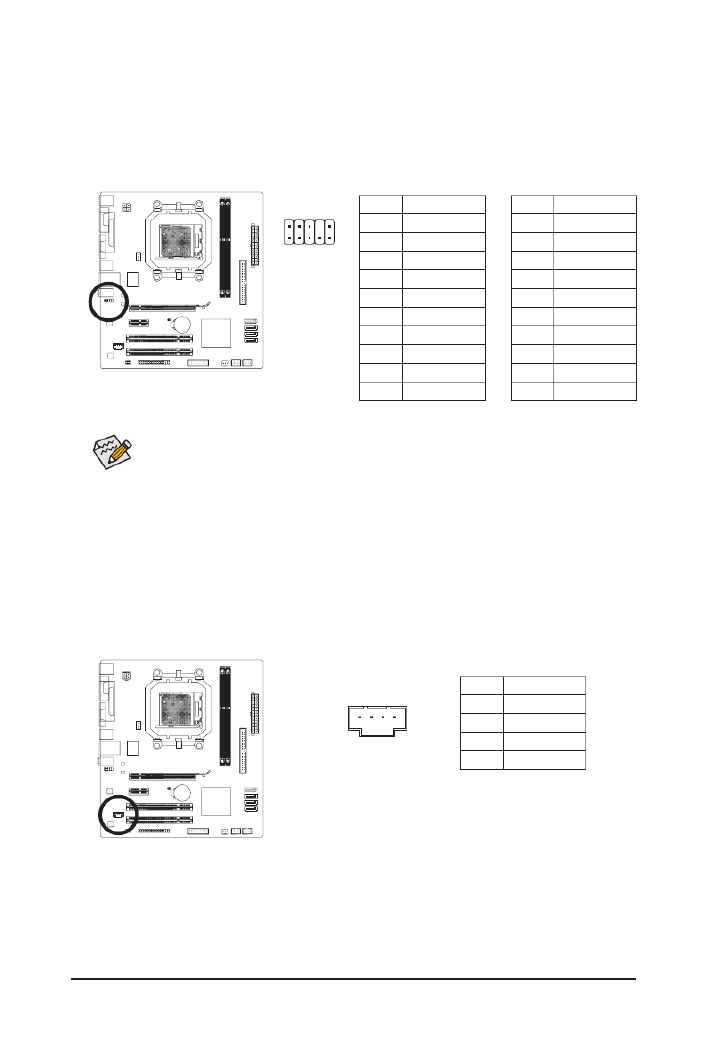
Hardware Installation - 26 -
9) F_AUDIO (Front Panel Audio Header)
ThefrontpanelaudioheadersupportsIntelHighDenitionaudio(HD)andAC'97audio.Youmayconn
your chassis front panel audio module to this header. Make sure the wire assignments of the module con-
nector match the pin assignments of the motherboard header. Incorrect connection between the module
connector and the motherboard header will make the device unable to work or even damage it.
PinNo. Denition
1 MIC2_L
2 GND
3 MIC2_R
4 -ACZ_DET
5 LINE2_R
6 GND
7 FAUDIO_JD
8 No Pin
9 LINE2_L
10 GND
PinNo. Denition
1 MIC
2 GND
3 MIC Power
4 NC
5 Line Out (R)
6 NC
7 NC
8 No Pin
9 Line Out (L)
10 NC
For HD Front Panel Audio: For AC'97 Front Panel Audio:
• The front panel audio header supports HD audio by default. If your chassis provides an AC'97
front panel audio module, refer to the instructions on how to activate AC'97 functionality via
theaudiosoftwareinChapter5,"Conguring2/4/5.1/7.1-ChannelAudio."
• Audio signals will be present on both of the front and back panel audio connections simultane-
ously. If you want to mute the back panel audio (only supported when using an HD front panel
audiomodule),refertoChapter5,"Conguring2/4/5.1/7.1-ChannelAudio."
• Some chassis provide a front panel audio module that has separated connectors on each wire
instead of a single plug. For information about connecting the front panel audio module that
has different wire assignments, please contact the chassis manufacturer.
10) CD_IN (CD In Connector)
You may connect the audio cable that came with your optical drive to the header.
PinNo. Denition
1 CD-L
2 GND
3 GND
4 CD-R
1
91
102

- 27 - Hardware Installation
12) F_USB1/F_USB2 (USB Headers)
TheheadersconformtoUSB2.0/1.1specication.EachUSBheadercanprovidetwoUSBportsviaa
optional USB bracket. For purchasing the optional USB bracket, please contact the local dealer.
PinNo. Denition
1 Power (5V)
2 Power (5V)
3 USB DX-
4 USB DY-
5 USB DX+
6 USB DY+
7 GND
8 GND
9 No Pin
10 NC
• Do not plug the IEEE 1394 bracket (2x5-pin) cable into the USB header.
• Prior to installing the USB bracket, be sure to turn off your computer and unplug the power
cord from the power outlet to prevent damage to the USB bracket.
10
9
2
1
11) SPDIF_IO (S/PDIF In/Out Header)
This header supports digital S/PDIF In/Out. Via an optional S/PDIF In and Out cable, this header can
connect to an audio device that supports digital audio out and an audio system that supports digital au-
dio in. For purchasing the optional S/PDIF In and Out cable, please contact the local dealer.
PinNo. Denition
1 Power
2 No Pin
3 SPDIF
4 SPDIFI
5 GND
6 GND
5 1
6 2

Hardware Installation - 28 -
13) CLR_CMOS (Clearing CMOS Jumper)
UsethisjumpertocleartheCMOSvalues(e.g.dateinformationandBIOScongurations)andrese
the CMOS values to factory defaults. To clear the CMOS values, place a jumper cap on the two pins to
temporarily short the two pins or use a metal object like a screwdriver to touch the two pins for a few
seconds.
• Always turn off your computer and unplug the power cord from the power outlet before clear-
ing the CMOS values.
• After clearing the CMOS values and before turning on your computer, be sure to remove the
jumper cap from the jumper. Failure to do so may cause damage to the motherboard.
• After system restart, go to BIOS Setup to load factory defaults (select Load Optimized De-
faults)ormanuallycongure theBIOSsettings(refertoChapter2,"BIOSSetup," for BIOS
congurations).
Open: Normal
Short: Clear CMOS Values
14) BAT (Battery)
Thebatteryprovidespowertokeepthevalues(suchasBIOScongurations,date,andtimeinformation
in the CMOS when the computer is turned off. Replace the battery when the battery voltage drops to a
low level, or the CMOS values may not be accurate or may be lost.
You may clear the CMOS values by removing the battery:
1. Turn off your computer and unplug the power cord.
2. Gently remove the battery from the battery holder and wait for one
minute. (Or use a metal object like a screwdriver to touch the positive
and negative terminals of the battery holder, making them short for 5
seconds.)
3. Replace the battery.
4. Plug in the power cord and restart your computer.
• Always turn off your computer and unplug the power cord before replacing the battery.
• Replace the battery with an equivalent one. Danger of explosion if the battery is replaced with
an incorrect model.
• Contact the place of purchase or local dealer if you are not able to replace the battery by your-
self or uncertain about the battery model.
• When installing the battery, note the orientation of the positive side (+) and the negative side (-)
of the battery (the positive side should face up).
• Used batteries must be handled in accordance with local environmental regulations.

- 29 - BIOS Setup
BIOS (Basic Input and Output System) records hardware parameters of the system in the CMOS on the
motherboard. Its major functions include conducting the Power-On Self-Test (POST) during system startup,
saving system parameters and loading operating system, etc. BIOS includes a BIOS Setup program that
allowsthe usertomodifybasicsystem congurationsettings ortoactivate certainsystem features.Whe
the power is turned off, the battery on the motherboard supplies the necessary power to the CMOS to keep
thecongurationvaluesintheCMOS.
To access the BIOS Setup program, press the <Delete> key during the POST when the power is turned on.
To see more advanced BIOS Setup menu options, you can press <Ctrl> + <F1> in the main menu of the
BIOS Setup program.
To upgrade the BIOS, use either the GIGABYTE Q-Flash or @BIOS utility.
• Q-Flash allows the user to quickly and easily upgrade or back up BIOS without entering the operating
system.
• @BIOS is a Windows-based utility that searches and downloads the latest version of BIOS from the
Internet and updates the BIOS.
For instructions on using the Q-Flash and @BIOS utilities, refer to Chapter 4, "BIOS Update Utilities."
Chapter 2 BIOS Setup
• BecauseBIOS ashing ispotentially risky, ifyoudo notencounter problemsusingthe curren
versionof BIOS, itisrecommended thatyounot ash theBIOS.To ash theBIOS, doit wi
caution.InadequateBIOSashingmayresultinsystemmalfunction.
• BIOS will emit a beep code during the POST. Refer to Chapter 5, "Troubleshooting," for the beep
codes description.
• It is recommended that you not alter the default settings (unless you need to) to prevent system
instability or other unexpected results. Inadequately altering the settings may result in system's
failure to boot. If this occurs, try to clear the CMOS values and reset the board to default values.
(Refer to the "Load Optimized Defaults" section in this chapter or introductions of the battery/
clearing CMOS jumper in Chapter 1 for how to clear the CMOS values.)

BIOS Setup - 30 -
2-1 Startup Screen
The following screens may appear when the computer boots.
Function Keys:
<DEL>: BIOS SETUP
Press the <Delete> key to enter BIOS Setup or to access the Q-Flash utility in BIOS Setup.
<F9>: XPRESS RECOVERY2
If you have ever entered Xpress Recovery2 to back up hard drive data using the driver disk, the <F9>
key can be used for subsequent access to Xpress Recovery2 during the POST. For more information,
refer to Chapter 4, "Xpress Recovery2."
<F12>: BOOT MENU
BootMenuallowsyoutosettherstbootdevicewithoutenteringBIOSSetup.InBootMenu,usetheup
arrow key <
h> or the down arrow key <
i>toselecttherstbootdevice,thenpress<Enter>toaccept.
ToexitBootMenu,press<Esc>.ThesystemwilldirectlybootfromthedeviceconguredinBootMenu.
Note: The setting in Boot Menu is effective for one time only. After system restart, the device boot order
willstillbebasedonBIOSSetupsettings.YoucanaccessBootMenuagaintochangetherstbootde-
vice setting as needed.
<END>: Q-FLASH
Pressthe<End>keytoaccesstheQ-FlashutilitydirectlywithouthavingtoenterBIOSSetuprst.
Motherboard Model
BIOS Version
Award Modular BIOS v6.00PG, An Energy Star Ally
Copyright (C) 1984-2009, Award Software, Inc.
M68MT-S2P D4
.
.
.
<DEL>:BIOSSetup<F9>:XpressRecovery2<F12>:BootMenu<End>:Qash
11/27/2009-NF-MCP68-6A61KG0FC-00
Function Keys

- 33 - BIOS Setup
2-3 MB Intelligent Tweaker(M.I.T.)
Whether the system will work stably with the overclock settings you made is dependent on your over-
allsystemcongurations.IncorrectlydoingoverclockmayresultindamagetoCPU,chipset,or
memory and reduce the useful life of these components. This page is for advanced users only and
we recommend you not to alter the default settings to prevent system instability or other unexpected
results. (Inadequately altering the settings may result in system's failure to boot. If this occurs, clear
the CMOS values and reset the board to default values.)
CMOS Setup Utility-Copyright (C) 1984-2009 Award Software
MB Intelligent Tweaker(M.I.T.)
Set Memory Clock [Auto]
x Memory Clock x5.33 1066Mhz
DRAMConguration [PressEnter]
CPU NB VID Control [Normal]
CPU Voltage Control [Normal]
DDR3 Voltage Control [Auto]
Normal CPU Vcore 1.3500V
higf
: Move Enter: Select +/-/PU/PD: Value F10: Save ESC: Exit F1: General Help
F5: Previous Values F6: Fail-Safe Defaults F7: Optimized Defaults
Item Help
Menu Level
Set Memory Clock
Determines whether to manually set the memory clock. lets BIOS automatically set the memory Auto
clock as required. Manualallowsthememoryclockcontrolitembelowtobecongurable.(Default:Auto)
Memory Clock
ThisoptioniscongurableonlywhenSet Memory Clock Manual is set to .
X4.00 Sets Memory Clock to X4.00.
X5.33 Sets Memory Clock to X5.33.
X6.66 Sets Memory Clock to X6.66.
X8.00 Sets Memory Clock to X8.00.

BIOS Setup - 34 -
DRAM Conguration
CMOS Setup Utility-Copyright (C) 1984-2009 Award Software
DRAMConguration
higf: Move Enter: Select +/-/PU/PD: Value F10: Save ESC: Exit F1: General Help
F5: Previous Values F6: Fail-Safe Defaults F7: Optimized Defaults
Item Help
Menu Level
DCTs Mode [Unganged]
DDR3 Timing Items [Auto] SPD Auto
x CAS# latency Auto 7T 7T
x RAS to CAS R/W Delay Auto 7T 7T
x Row Precharge Time Auto 7T 7T
x Minimum RAS Active Time Auto 20T 20T
x 1T/2T Command Timing Auto -- --
x TwTr Command Delay Auto 4T 4T
x Trfc0 for DIMM1 Auto 110ns 110ns
x Trfc1 for DIMM3 Auto -- --
x Write Recovery Time Auto 8T 8T
x Precharge Time Auto 4T 4T
x Row Cycle Time Auto 27T 27T
x RAS to RAS Delay Auto 4T 4T
CKE Power Down Mode [Disabled]
CKE Power Down Control [per Channel]
DCTs Mode
Allows you to set memory control mode.
Ganged Sets memory control mode to single dual-channel.
Unganged Sets memory control mode to two single-channel. (Default)
DDR3 Timing Items
ManualallowsallDDR3Timingitemsbelowtobecongurable.
Options are: Auto (default), Manual.
CAS# latency
Options are: Auto (default), 4T~12T.
RAS to CAS R/W Delay
Options are: Auto (default), 5T~12T.
Row Precharge Time
Options are: Auto (default), 5T~12T.
Minimum RAS Active Time
Options are: Auto (default), 15T~30T.
1T/2T Command Timing
Options are: Auto (default), 1T, 2T.
TwTr Command Delay
Options are: Auto (default), 4T~7T.
Trfc0 for DIMM1
Options are: Auto (default), 90ns, 110ns, 160ns, 300ns, 350ns.
Trfc1 for DIMM3
Options are: Auto (default), 90ns, 110ns, 160ns, 300ns, 350ns.
Write Recovery Time
Options are: Auto (default), 5T~12T.

- 35 - BIOS Setup
Precharge Time
Options are: Auto (default), 4T~7T.
Row Cycle Time
Options are: Auto (default), 11T~42T.
RAS to RAS Delay
Options are: Auto (default), 4T~7T.
CKE Power Down Mode
Determines whether to set the memory to power down mode when the CKE pin is closed. (Default: Dis-
abled)
CKE Power Down Control
Allows you to select a CKE power down mode. Options are per Channel (Default), per CS.
CPU NB VID Control
Allows you to set the CPU Northbridge VID voltage. sets the CPU Northbridge VID voltage as re-Auto
quired. The adjustable range is dependent on the CPU being installed. (Default: Normal)
Note: Increasing CPU voltage may result in damage to your CPU or reduce the useful life of the CPU.
CPU Voltage Control
Allows you to set the CPU voltage. sets the CPU voltage as required. The adjustable range is de-Auto
pendent on the CPU being installed. (Default: Normal)
Note: Increasing CPU voltage may result in damage to your CPU or reduce the useful life of the CPU.
DDR3 Voltage Control
Allows you to set the memory voltage.
Normal Supplies the memory voltage as required. (Default)
+0.05V ~ +0.4V The adjustable range is from +0.05V to +0.4V.
Note: Increasing memory voltage may result in damage to the memory or reduce the useful life of the
memory.
Normal CPU Vcore
Displays the normal operating voltage of your CPU.

BIOS Setup - 36 -
Date (mm:dd:yy)
Setsthesystemdate.Thedateformatisweek(read-only),month,dateandyear.Selectthedesiredeld
and use the up arrow or down arrow key to set the date.
Time (hh:mm:ss)
Setsthesystemtime.Forexample,1p.m.is13:0:0.Selectthedesiredeldandusetheuparrowor
down arrow key to set the time.
IDE Channel 0 Master/Slave
IDE HDD Auto-Detection
Press <Enter> to autodetect the parameters of the IDE/SATA device on this channel.
IDE Channel 0 Master/Slave
CongureyourIDE/SATAdevicesbyusingoneofthetwomethodsbelow:
•Auto Lets the BIOS automatically detect IDE/SATA devices during the POST. (Default)
•None If no IDE/SATA devices are used, set this item to so the system will skip None
the detection of the device during the POST for faster system startup.
Access Mode Sets the hard drive access mode. Options are: Auto (default), CHS, LBA, Large.
IDE Channel 2, 3, 4, 5 Master
IDE Auto-Detection
Press <Enter> to autodetect the parameters of the IDE/SATA device on this channel.
Extended IDE Drive
CongureyourIDE/SATAdevicesbyusingoneofthetwomethodsbelow:
•Auto Lets the BIOS automatically detect IDE/SATA devices during the POST. (Default)
•None If no IDE/SATA devices are used, set this item to so the system will skip None
the detection of the device during the POST for faster system startup.
Access Mode Sets the hard drive access mode. Options are: Auto (default), Large.
2-4 Standard CMOS Features
CMOS Setup Utility-Copyright (C) 1984-2009 Award Software
Standard CMOS Features
Date (mm:dd:yy) Wed, Nov 25 2009
Time (hh:mm:ss) 22:31:24
IDE Channel 0 Master [None]
IDE Channel 0 Slave [None]
IDE Channel 2 Master [None]
IDE Channel 3 Master [None]
IDE Channel 4 Master [None]
IDE Channel 5 Master [None]
Drive A [1.44M, 3.5"]
Floppy 3 Mode Support [Disabled]
Halt On [All, But Keyboard]
Base Memory 640K
Extended Memory 1918M
higf
: Move Enter: Select +/-/PU/PD: Value F10: Save ESC: Exit F1: General Help
F5: Previous Values F6: Fail-Safe Defaults F7: Optimized Defaults
Item Help
Menu Level

- 37 - BIOS Setup
Thefollowingeldsdisplayyourharddrivespecications.Ifyouwishtoentertheparametersmanually,
refer to the information on the hard drive.
Capacity Approximate capacity of the currently installed hard drive.
Cylinder Number of cylinders.
Head Number of heads.
Precomp Write precompensation cylinder.
Landing Zone Landing zone.
Sector Number of sectors.
Drive A
Allowsyoutoselectthetypeofoppydiskdriveinstalledinyoursystem.Ifyoudonotinstallaoppy
disk drive, set this item to . Options are: None, 360K/5.25", 1.2M/5.25", 720K/3.5", 1.44M/3.5", None
2.88M/3.5".
Floppy 3 Mode Support
Allows youto specify whether the installedoppy disk drive is3-mode oppy disk drive, aJapanese
standardoppydiskdrive.Optionsare:Disabled(default),DriveA.
Halt On
Allows you to determine whether the system will stop for an error during the POST.
All Errors Whenever the BIOS detects a non-fatal error the system boot will stop.
No Errors The system boot will not stop for any error.
All, But Keyboard The system boot will not stop for a keyboard error but stop for all other errors.
(Default)
All,ButDiskette Thesystembootwillnotstopforaoppydiskdriveerrorbutstopforallother
errors.
All,ButDisk/Key Thesystembootwillnotstopforakeyboardoraoppydiskdriveerrorbutit
will stop for all other errors.
Memory
Theseeldsareread-onlyandaredeterminedbytheBIOSPOST.
Base Memory Also called conventional memory. Typically, 640 KB will be reserved for the
MS-DOS operating system.
Extended Memory The amount of extended memory.
BIOS Setup - 38 -
2-5 Advanced BIOS Features
Virtualization
Virtualization allows a platform to run multiple operating systems and applications in independent parti-
tions. With virtualization, one computer system can function as multiple virtual systems.
(Default: Enabled)
AMD K8 Cool&Quiet control
Auto Lets the AMD Cool'n'Quiet driver dynamically adjust the CPU clock and VID to
reduce heat output from your computer and its power consumption. (Default)
Disabled Disables this function.
Hard Disk Boot Priority
Speciesthesequenceofloadingtheoperatingsystemfromtheinstalledharddrives.Usetheupor
down arrow key to select a hard drive, then press the plus key <+> (or <PageUp>) or the minus key <-> (or
<PageDown>)tomoveitupordownonthelist.Press<Esc>toexitthismenuwhennished.
First/Second/Third Boot Device
Speciesthebootorder fromtheavailabledevices. Usetheupor downarrowkeyto selectadevice
and press <Enter> to accept. Options are: Floppy, LS120, Hard Disk, CDROM, ZIP, USB-FDD, USB-ZIP,
USB-CDROM, USB-HDD, Legacy LAN, Disabled.
Password Check
Specieswhether apassword isrequired everytimethesystemboots,oronlywhen youenter BIOS
Setup.Afterconguringthisitem,setthepassword(s)undertheSet Supervisor/User Password item in
the BIOS Main Menu.
Setup A password is only required for entering the BIOS Setup program. (Default)
System A password is required for booting the system and for entering the BIOS Setup
program.
CMOS Setup Utility-Copyright (C) 1984-2009 Award Software
Advanced BIOS Features
Virtualization [Enabled]
AMD K8 Cool&Quiet control [Auto]
Hard Disk Boot Priority [Press Enter]
First Boot Device [Floppy]
Second Boot Device [Hard Disk]
Third Boot Device [CDROM]
Password Check [Setup]
HDD S.M.A.R.T. Capability [Disabled]
Away Mode [Disabled]
Backup BIOS Image to HDD [Disabled]
Init Display First [PEG]
Frame Buffer Size [64M]
Onboard GPU [Enable If No Ext PEG]
higf
: Move Enter: Select +/-/PU/PD: Value F10: Save ESC: Exit F1: General Help
F5: Previous Values F6: Fail-Safe Defaults F7: Optimized Defaults
Item Help
Menu Level

- 39 - BIOS Setup
HDD S.M.A.R.T. Capability
Enables or disables the S.M.A.R.T. (Self Monitoring and Reporting Technology) capability of your hard
drive. This feature allows your system to report read/write errors of the hard drive and to issue warnings
when a third party hardware monitor utility is installed. (Default: Enabled)
Away Mode
Enables or disables Away Mode in Windows XP Media Center operating system. Away Mode allows the
system to silently perform unattended tasks while in a low-power mode that appears off.
(Default: Disabled)
Backup BIOS Image to HDD
AllowsthesystemtocopytheBIOSimageletotheharddrive.IfthesystemBIOSiscorrupted,itwill
berecoveredfromthisimagele.(Default:Disabled)
Init Display First
Species the rst initiation of the monitor display from the installed PCI graphics card, PCI Express
graphics card, or the onboard graphics.
PCISlot SetsthePCIgraphicscardastherstdisplay.
OnboardVGA Setstheonboardgraphicsastherstdisplay.
PEG SetsthePCIExpressgraphicscardastherstdisplay.(Default)
Frame Buffer Size
Frame buffer size is the total amount of system memory allocated solely for the onboard graphics controller.
MS-DOS, for example, will use only this memory for display. Options are: Disabled, 32MB, 64MB (Default),
128MB, 256MB.
Onboard GPU
Enables or disables the onboard graphics function.
Enable If No Ext PEG
Activates the onboard graphics only if no PCI Express graphics card is installed. (Default)
Always Enable
Always activates the onboard graphics, whether or not a PCI Express card is installed. If you wish to set
upadualviewconguration,setthisitemtoAlwaysEnable.

BIOS Setup - 40 -
2-6 Integrated Peripherals
On-Chip IDE Channel
Enables or disables the integrated IDE controller. (Default: Enabled)
NV Serial-ATA Controller
Enables or disables the integrated SATA controller(s). You can select whether to enable all SATA control-
lersoronlytherstSATAcontroller.(Default:AllEnabled)
IDE Prefetch Mode
Enables or disables prefetch mode for the integrated IDE controller. Enabled activates the IDE prefetch
buffer to enhance hard drive performance. (Default: Enabled)
USB Memory Type
SpeciesthetypeofmemoryallocatedforUSBdevices.Optionsare:SHADOW(default),BaseMemory
(640K).
CMOS Setup Utility-Copyright (C) 1984-2009 Award Software
Integrated Peripherals
On-Chip IDE Channel [Enabled]
NV Serial-ATA Controller [All Enabled]
IDE Prefetch Mode [Enabled]
USB Memory Type [SHADOW]
Serial-ATARAIDCong [PressEnter]
Onboard Audio Function [Auto]
On-Chip MAC Lan [Auto]
Onboard LAN Boot ROM [Disabled]
Onboard Serial Port 1 [3F8/IRQ4]
Onboard Parallel Port [378/IRQ7]
Parallel Port Mode [SPP]
x ECP Mode Use DMA 3
On-Chip USB [V1.1+V2.0]
USB Keyboard Support [Disabled]
USB Mouse Support [Disabled]
Legacy USB storage detect [Enabled]
higf
: Move Enter: Select +/-/PU/PD: Value F10: Save ESC: Exit F1: General Help
F5: Previous Values F6: Fail-Safe Defaults F7: Optimized Defaults
Item Help
Menu Level
Serial-ATA RAID Cong
CMOS Setup Utility-Copyright (C) 1984-2009 Award Software
Serial-ATARAIDCong
NV SATA RAID function [Disabled]
x NV SATA 1 Primary RAID Enabled
x NV SATA 1 Secondary RAID Enabled
x NV SATA 2 Primary RAID Enabled
x NV SATA 2 Secondary RAID Enabled
higf
: Move Enter: Select +/-/PU/PD: Value F10: Save ESC: Exit F1: General Help
F5: Previous Values F6: Fail-Safe Defaults F7: Optimized Defaults
Item Help
Menu Level
NV SATA RAID function
EnablesordisablesRAIDfortheintegratedSATA3Gb/scontrollers.Enabledallowsyoutocongure
RAID for individual SATA channel. (Default: Disabled)

- 41 - BIOS Setup
NV SATA 1 Primary RAID
EnablesordisablesRAIDfortherstchanneloftherstintegratedSATA3Gb/scontroller.Thisitemis
congurableonlyiftheNV SATA RAID function item is set to Enabled. (Default: Enabled)
NV SATA 1 Secondary RAID
EnablesordisablesRAIDforthesecondchanneloftherstintegratedSATA3Gb/scontroller.Thisitem
iscongurableonlyiftheNV SATA RAID function item is set to Enabled. (Default: Enabled)
NV SATA 2 Primary RAID
EnablesordisablesRAIDfortherstchannelofthesecondintegratedSATA3Gb/scontroller.Thisitem
iscongurableonlyiftheNV SATA RAID function item is set to Enabled. (Default: Enabled)
NV SATA 2 Secondary RAID
EnablesordisablesRAIDfortherstchannelofthesecondintegratedSATA3Gb/scontroller.Thisitem
iscongurableonlyiftheNV SATA RAID function item is set to Enabled. (Default: Enabled)
Onboard Audio Function
Enables or disables the onboard audio function. (Default: Auto)
If you wish to install a 3rd party add-in audio card instead of using the onboard audio, set this item to
Disabled.
On-Chip MAC Lan
Enables or disables the onboard LAN function. (Default: Auto)
If you wish to install a 3rd party add-in network card instead of using the onboard LAN, set this item to
Disabled.
Onboard LAN Boot ROM
Allows you to decide whether to activate the boot ROM integrated with the onboard LAN chip.
(Default: Disabled)
Onboard Serial Port 1
Enablesordisablestherstserialport andspeciesitsbaseI/Oaddressand correspondinginterrupt.
Options are: Auto, 2F8/IRQ3, 3F8/IRQ4(default), 3E8/IRQ4, 2E8/IRQ3, Disabled.
Onboard Parallel Port
Enablesordisablestheonboardparallelport(LPT)andspeciesitsbaseI/Oaddressandcorrespond-
ing interrupt. Options are: 378/IRQ7 (default), 278/IRQ5, 3BC/IRQ7, Disabled.
Parallel Port Mode
Selects an operating mode for the onboard parallel (LPT) port. Options are: SPP (Standard Parallel Port)
(default), EPP (Enhanced Parallel Port), ECP (Extended Capabilities Port), ECP+EPP.
ECP Mode Use DMA
SelectsDMAchannelfortheLPTportinECPmode.ThisitemiscongurableonlyifParallel Port Mode
is set to or mode. Options are: 3 (default), 1. ECP ECP+EPP
On-Chip USB
V1.1+V2.0 Enables the USB 1.1 and USB 2.0 controllers. (Default)
V1.1 Enables only the USB 1.1 controller.
Disabled Disables the onboard USB controller.

BIOS Setup - 42 -
USB Keyboard Support
Allows USB keyboard to be used in MS-DOS. (Default: Disabled)
USB Mouse Support
Allows USB mouse to be used in MS-DOS. (Default: Disabled)
Legacy USB storage detect
Determines whether to detectUSBstoragedevices,includingUSBashdrivesandUSBharddrives
during the POST. (Default: Enabled)

- 43 - BIOS Setup
ACPI Suspend Type
SpeciestheACPIsleepstatewhenthesystementerssuspend.
S1(POS) Enables the system to enter the ACPI S1 (Power on Suspend) sleep state.
In S1 sleep state, the system appears suspended and stays in a low power mode.
The system can be resumed at any time.
S3(STR) Enables the system to enter the ACPI S3 (Suspend to RAM) sleep state (default).
In S3 sleep state, the system appears to be off and consumes less power than in
the S1 state. When signaled by a wake-up device or event, the system resumes to
its working state exactly where it was left off.
Soft-Off by Power button
ConguresthewaytoturnoffthecomputerinMS-DOSmodeusingthepowerbutton.
Instant-Off Press the power button and then the system will be turned off instantly. (Default)
Delay 4 Sec. Press and hold the power button for 4 seconds to turn off the system. If the power
button is pressed for less than 4 seconds, the system will enter suspend mode.
PME Event Wake Up
Allows the system to be awakened from an ACPI sleep state by a wake-up signal from a PCI or PCIe de-
vice. Note: To use this function, you need an ATX power supply providing at least 1A on the +5VSB lead.
(Default: Enabled)
Modem Ring On
Allows the system to be awakened from an ACPI sleep state by a wake-up signal from a modem that
supports wake-up function. (Default: Enabled)
USB Resume from Suspend
Allows the system to be awakened from ACPI S3 sleep state by a wake-up signal from the installed USB
device. (Default: Enabled)
(Note) Supported on Windows 7/Vista operating system only.
2-7 Power Management Setup
CMOS Setup Utility-Copyright (C) 1984-2009 Award Software
Power Management Setup
ACPI Suspend Type [S3(STR)]
Soft-Off by Power button [Instant-Off]
PME Event Wake Up [Enabled]
Modem Ring On [Enabled]
USB Resume from Suspend [Enabled]
Power-On by Alarm [Disabled]
x Day of Month Alarm Everyday
x Time (hh:mm:ss) Alarm 0 : 0 : 0
HPET Support
(Note) [Enabled]
HPET Mode
(Note) [32-bit mode]
Power On By Mouse [Disabled]
Power On By Keyboard [Disabled]
x KB Power ON Password Enter
AC Back Function [Soft-Off]
EuP Support [Disabled]
higf
: Move Enter: Select +/-/PU/PD: Value F10: Save ESC: Exit F1: General Help
F5: Previous Values F6: Fail-Safe Defaults F7: Optimized Defaults
Item Help
Menu Level

- 45 - BIOS Setup
PCI 1 IRQ Assignment
Auto BIOSauto-assignsIRQtotherstPCIslot.(Default)
3,4,5,7,9,10,11,12,14,15 AssignsIRQ3,4,5,7,9,10,11,12,14,15totherstPCIslot.
PCI 2 IRQ Assignment
Auto BIOS auto-assigns IRQ to the second PCI slot. (Default)
3,4,5,7,9,10,11,12,14,15 Assigns IRQ 3,4,5,7,9,10,11,12,14,15 to the second PCI slot.
2-8 PnP/PCI Congurations
CMOS Setup Utility-Copyright (C) 1984-2009 Award Software
PnP/PCICongurations
PCI 1 IRQ Assignment [Auto]
PCI 2 IRQ Assignment [Auto]
higf
: Move Enter: Select +/-/PU/PD: Value F10: Save ESC: Exit F1: General Help
F5: Previous Values F6: Fail-Safe Defaults F7: Optimized Defaults
Item Help
Menu Level
BIOS Setup - 46 -
Reset Case Open Status
Keeps or clears the record of previous chassis intrusion status. clears the record of previous Enabled
chassis intrusion status and the Case Openedeldwillshow"No"atnextboot.(Default:Disabled)
Case Opened
Displays the detection status of the chassis intrusion detection device attached to the motherboard CI
header.Ifthesystemchassiscoverisremoved,thiseldwillshow"Yes",otherwiseitwillshow"No".To
clear the chassis intrusion status record, set to , save the settings to Reset Case Open Status Enabled
the CMOS, and then restart your system.
Current Voltage(V) Vcore/DDR2 1.8V/+3.3V/+12V
Displays the current system voltages.
Current System/CPU Temperature
Displays current system/CPU temperature.
Current CPU/SYSTEM FAN Speed (RPM)
Displays current CPU/system fan speed.
System/CPU Warning Temperature
Sets the warning threshold for system/CPU temperature. When system/CPU temperature exceeds
the threshold, BIOS will emit warning sound. Options are: Disabled (default), 60oC/140oF, 70oC/158oF,
80oC/176oF, 90oC/194oF.
CPU/SYSTEM FAN Fail Warning
Allows the system to emit warning sound if the CPU/system fan is not connected or fails. Check the fan
condition or fan connection when this occurs. (Default: Disabled)
CPU Smart FAN Control
Enables or disables the CPU fan speed control function. allows the CPU fan to run at different Enabled
speed according to the CPU temperature. You can adjust the fan speed with EasyTune based on system
requirements. If disabled, the CPU fan runs at full speed. (Default: Enabled)
2-9 PC Health Status
CMOS Setup Utility-Copyright (C) 1984-2009 Award Software
PC Health Status
Reset Case Open Status [Disabled]
Case Opened No
Vcore 1.364V
DDR3 1.5V 1.520V
+3.3V 3.280V
+12V 12.048V
Current System Temperature 38
oC
Current CPU Temperature 36
oC
Current CPU FAN Speed 1962 RPM
Current SYSTEM FAN Speed 0 RPM
System Warning Temperature [Disabled]
CPU Warning Temperature [Disabled]
CPU FAN Fail Warning [Disabled]
SYSTEM FAN Fail Warning [Disabled]
CPU Smart FAN Control [Enabled]
CPU Smart FAN Mode [Auto]
higf
: Move Enter: Select +/-/PU/PD: Value F10: Save ESC: Exit F1: General Help
F5: Previous Values F6: Fail-Safe Defaults F7: Optimized Defaults
Item Help
Menu Level

- 47 - BIOS Setup
CPU Smart FAN Mode
SpecieshowtocontrolCPUfanspeed.ThisitemiscongurableonlyifCPU Smart FAN Control is set
to . Enabled
Auto Lets the BIOS automatically detect the type of CPU fan installed and sets the optimal
CPU fan control mode. (Default)
Voltage Sets Voltage mode for a 3-pin CPU fan.
PWM Sets PWM mode for a 4-pin CPU fan.
BIOS Setup - 48 -
Press <Enter> on this item and then press the <Y> key to load the safest BIOS default settings.
In case system instability occurs, you may try to load Fail-Safe defaults, which are the safest and most stable
BIOS settings for the motherboard.
2-10 Load Fail-Safe Defaults
CMOS Setup Utility-Copyright (C) 1984-2009 Award Software
Load Fail-Safe Defaults
MB Intelligent Tweaker(M.I.T.)
Standard CMOS Features
Advanced BIOS Features
Integrated Peripherals
Power Manageme
PnP/PCICongur
PC Health Status
ESC: Quit
higf: Select Item
F8: Q-Flash F10: Save & Exit Setup
Load Fail-Safe Defaults
Load Optimized Defaults
Set Supervisor Password
Set User Password
Load Fail-Safe Defaults (Y/N)? N
Press <Enter> on this item and then press the <Y> key to load the optimal BIOS default settings.
The BIOS defaults settings help the system to operate in optimum state. Always load the Optimized defaults
after updating the BIOS or after clearing the CMOS values.
2-11 Load Optimized Defaults
CMOS Setup Utility-Copyright (C) 1984-2009 Award Software
Load Optimized Defaults
MB Intelligent Tweaker(M.I.T.)
Standard CMOS Features
Advanced BIOS Features
Integrated Peripherals
Power Manageme
PnP/PCICongur
PC Health Status
ESC: Quit
higf: Select Item
F8: Q-Flash F10: Save & Exit Setup
Load Fail-Safe Defaults
Load Optimized Defaults
Set Supervisor Password
Set User Password
Load Optimized Defaults (Y/N)? N

- 49 - BIOS Setup
Press <Enter> on this item and type the password with up to 8 characters and then press <Enter>. You will
berequestedtoconrmthepassword.Typethepasswordagainandpress<Enter>.
The BIOS Setup program allows you to specify two separate passwords:
Supervisor Password
When a system password is set and the item in is set to Password Check Advanced BIOS Features
Setup, you must enter the supervisor password for entering BIOS Setup and making BIOS changes.
When the item is set to , you must enter the supervisor password (or user Password Check System
password) at system startup and when entering BIOS Setup.
User Password
When the item is set to , you must enter the supervisor password (or user Password Check System
password) at system startup to continue system boot. In BIOS Setup, you must enter the supervisor
password if you wish to make changes to BIOS settings. The user password only allows you to view the
BIOS settings but not to make changes.
To clear the password, press <Enter> on the password item and when requested for the password, press
<Enter> again. The message "PASSWORD DISABLED" will appear, indicating the password has been can-
celled.
2-12 Set Supervisor/User Password
CMOS Setup Utility-Copyright (C) 1984-2009 Award Software
Change/Set/Disable Password
MB Intelligent Tweaker(M.I.T.)
Standard CMOS Features
Advanced BIOS Features
Integrated Peripherals
Power Manageme
PnP/PCICongur
PC Health Status
ESC: Quit
higf: Select Item
F8: Q-Flash F10: Save & Exit Setup
Load Fail-Safe Defaults
Load Optimized Defaults
Set Supervisor Password
Set User Password
Enter Password:

BIOS Setup - 50 -
Press <Enter> on this item and press the <Y> key. This saves the changes to the CMOS and exits the BIOS
Setup program. Press <N> or <Esc> to return to the BIOS Setup Main Menu.
2-13 Save & Exit Setup
Press <Enter> on this item and press the <Y> key. This exits the BIOS Setup without saving the changes
made in BIOS Setup to the CMOS. Press <N> or <Esc> to return to the BIOS Setup Main Menu.
2-14 Exit Without Saving
CMOS Setup Utility-Copyright (C) 1984-2009 Award Software
Save Data to CMOS
MB Intelligent Tweaker(M.I.T.)
Standard CMOS Features
Advanced BIOS F
Integrated Periphe
Power Management Setup
PnP/PCICongurations
PC Health Status
ESC: Quit
higf: Select Item
F8: Q-Flash F10: Save & Exit Setup
Load Fail-Safe Defaults
Load Optimized Defaults
ord
Save & Exit Setup
Exit Without Saving
Save to CMOS and EXIT (Y/N)? Y
CMOS Setup Utility-Copyright (C) 1984-2009 Award Software
Abandon all Data
MB Intelligent Tweaker(M.I.T.)
Standard CMOS Features
Advanced BIOS F
Integrated Periphe
Power Management Setup
PnP/PCICongurations
PC Health Status
ESC: Quit
higf: Select Item
F8: Q-Flash F10: Save & Exit Setup
Load Fail-Safe Defaults
Load Optimized Defaults
ord
Save & Exit Setup
Exit Without Saving
Quit Without Saving (Y/N)? N

- 51 - Drivers Installation
3-1 Installing Chipset Drivers
Chapter 3 Drivers Installation
After inserting the driver disk, "Xpress Install" will automatically scan your system and then list all the drivers
that are recommended to install. You can click the button and "Xpress Install" will install all the rec-Install All
ommended drivers. Or click to manually select the drivers you wish to install.Install Single Items
• Beforeinstallingthedrivers,rstinstalltheoperatingsystem.
• After installing the operating system, insert the motherboard driver disk into your optical drive.
The driver Autorun screen is automatically displayed which looks like that shown in the screen
shot below. (If the driver Autorun screen does not appear automatically, go to My Computer,
double-click the optical drive and execute the .exe program.)Run
• Please ignore the popup dialog box(es) (e.g. the ) displayed Found New Hardware Wizard
when "Xpress Install" is installing the drivers. Failure to do so may affect the driver installation.
• Some device drivers will restart your system automatically during the driver installation. After the
system restart, "Xpress Install" will continue to install other drivers.
• After the drivers are installed, follow the on-screen instructions to restart your system. You can
install other applications included in the motherboard driver disk.
• For USB 2.0 driver support under the Windows XP operating system, please install the Windows
XP Service Pack 1 or later. After installing the SP1 (or later), if a question mark still exists in
Universal Serial Bus Controller Device Manager in , please remove the question mark (by
right-clicking your mouse and select ) and restart the system. (The system will then Uninstall
autodetect and install the USB 2.0 driver.)

Drivers Installation - 52 -
3-2 Application Software
This page displays all the utilities and applications that GIGABYTE develops and some free software. You
can click the button on the right of an item to install it.Install
3-3 Technical Manuals
This page provides GIGABYTE's application guides, content descriptions for this driver disk, and the mother-
board manuals.

- 53 - Drivers Installation
3-4 Contact
ForthedetailedcontactinformationoftheGIGABYTETaiwanheadquarterorworldwidebranchofces,click
the URL on this page to link to the GIGABYTE website.
3-5 System
This page provides the basic system information.

Drivers Installation - 54 -
3-6 Download Center
To update the BIOS, drivers, or applications, click the button to link to the GIGABYTE Download Center
website. The latest version of the BIOS, drivers, or applications will be displayed.
Produktspecifikationer
| Varumärke: | Gigabyte |
| Kategori: | moderkort |
| Modell: | GA-M68MT-S2P |
Behöver du hjälp?
Om du behöver hjälp med Gigabyte GA-M68MT-S2P ställ en fråga nedan och andra användare kommer att svara dig
moderkort Gigabyte Manualer

10 Mars 2025
3 Mars 2025
3 Mars 2025
18 Februari 2025
11 Februari 2025
11 Februari 2025
11 Februari 2025
11 Februari 2025
11 Februari 2025
11 Februari 2025
moderkort Manualer
- moderkort Asus
- moderkort Sharkoon
- moderkort Asrock
- moderkort Supermicro
- moderkort Evga
- moderkort Intel
- moderkort MSI
- moderkort ECS
- moderkort NZXT
- moderkort Foxconn
- moderkort Advantech
- moderkort Elitegroup
- moderkort EPoX
- moderkort Biostar
Nyaste moderkort Manualer
8 April 2025
8 April 2025
3 April 2025
3 April 2025
3 April 2025
3 April 2025
2 April 2025
2 April 2025
1 April 2025
30 Mars 2025