Gigabyte Z490 UD Bruksanvisning
Läs nedan 📖 manual på svenska för Gigabyte Z490 UD (48 sidor) i kategorin moderkort. Denna guide var användbar för 4 personer och betygsatt med 4.5 stjärnor i genomsnitt av 2 användare
Sida 1/48

To reduce the impacts on global warming, the packaging materials of this product
are recyclable and reusable. GIGABYTE works with you to protect the environment.
For more product details, please visit GIGABYTE's website.
Z490 UDZ490 UD AC
Z490 UD AC
Z490 UD
User's Manual
Rev. 1001
12ME-Z49UD-1001R

Copyright
© 2020 GIGA-BYTE TECHNOLOGY CO., LTD. All rights reserved.
The trademarks mentioned in this manual are legally registered to their respective owners.
Disclaimer
Information in this manual is protected by copyright laws and is the property of GIGABYTE.
Changes to the specications and features in this manual may be made by GIGABYTE
without prior notice.
No part of this manual may be reproduced, copied, translated, transmitted, or published in any
form or by any means without GIGABYTE's prior written permission.
In order to assist in the use of this product, carefully read the User's Manual.
For product-related information, check on our website at: https://www.gigabyte.com
Identifying Your Motherboard Revision
The revision number on your motherboard looks like this: "REV: X.X." For example, "REV:
1.0" means the revision of the motherboard is 1.0. Check your motherboard revision before
updating motherboard BIOS, drivers, or when looking for technical information.
Example:

- 3 -
Table of Contents
Z490 UD (AC) Motherboard Layout 4 .................................................................................
Chapter 1 Hardware Installation 5 .....................................................................................
1-1 Installation Precautions 5 ....................................................................................
1-2 ProductSpecications ...................................................................................... 6
1-3 Installing the CPU 9 ............................................................................................
1-4 Installing the Memory 9 .......................................................................................
1-5 Installing an Expansion Card 10 .........................................................................
1-6 Back Panel Connectors 10 ..................................................................................
1-7 Internal Connectors 12 ........................................................................................
Chapter 2 BIOS Setup 21 ..................................................................................................
2-1 Startup Screen 21 ...............................................................................................
2-2 The Main Menu 22 ..............................................................................................
2-3 Favorites (F11) 23 ...............................................................................................
2-4 Tweaker .......................................................................................................... 24
2-5 Settings .......................................................................................................... 29
2-6 System Info. 35 ...................................................................................................
2-7 Boot ................................................................................................................ 36
2-8 Save & Exit 39 .....................................................................................................
Chapter 3 Appendix 40 ......................................................................................................
3-1 ConguringaRAIDSet .................................................................................. 40
3-2 Installing an Intel® Optane™ Memory 42 ..............................................................
3-3 Drivers Installation 44 ..........................................................................................
RegulatoryNotices .................................................................................................... 45
Contact Us 48 ................................................................................................................
- 4 -
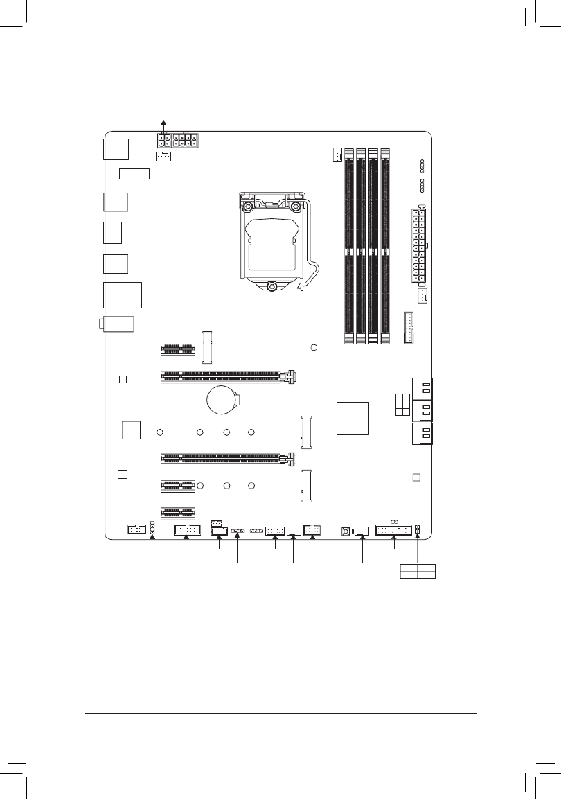
Z490 UD (AC) Motherboard Layout
* The box contents above are for reference only and the actual items shall depend on the product package you
obtain. The box contents are subject to change without notice.
Box Contents
5Z490 UD AC or Z490 UD Motherboard
5Motherboard driver disc 5Two SATA cables
5User's Manual 5One antennaj
KB_MS_USB
HDMI
U32
U32_LAN
LGA1200
ATX
AUDIO
ATX_12V_2X4
Intel® Z490
CLR_CMOS
M_BIOS
PCIEX1_1
PCIEX4
PCIEX16
PCIEX1_2
PCIEX1_3
F_U32
M2P_32G (Note)
CODEC
Z490 UD (AC)
F_PANELF_USB
LED_C1
F_AUDIO
COM SYS_FAN3
SPI_TPM
SYS_FAN1
SYS_FAN2
CPU_FAN
iTE®
Super I/O
80
SATA3 531
420
BAT
Realtek®
GbELAN
CPU DRAM
VGA BOOT
U32_G2
THB_C1
M2M_SB
426080
ATX_12V_2X2
DDR4_B1
DDR4_B2
DDR4_A1
DDR4_A2
D_LED2
LED_C2
QFLASH_PLUS
426080110
M2A_SB
SYS_FAN4D_LED1
SPDIF_O
CNVIj
(Note) TheM.2connectorisreservedonly.Nofunctionalities.
j Only for the Z490 UD AC.
QFLED
THB_C2

Chapter 1 Hardware Installation
1-1 Installation Precautions
The motherboard contains numerous delicate electronic circuits and components which can become
damaged as a result of electrostatic discharge (ESD). Prior to installation, carefully read the user's
manual and follow these procedures:
•Prior to installation, make sure the chassis is suitable for the motherboard.
•Prior to installation, do not remove or break motherboard S/N (Serial Number) sticker or
warranty sticker provided by your dealer. These stickers are required for warranty validation.
•Always remove the AC power by unplugging the power cord from the power outlet before
installing or removing the motherboard or other hardware components.
•When connecting hardware components to the internal connectors on the motherboard, make
sure they are connected tightly and securely.
•When handling the motherboard, avoid touching any metal leads or connectors.
•It is best to wear an electrostatic discharge (ESD) wrist strap when handling electronic
components such as a motherboard, CPU or memory. If you do not have an ESD wrist strap,
keepyourhandsdryandrsttouchametalobjecttoeliminatestaticelectricity.
•Prior to installing the motherboard, please have it on top of an antistatic pad or within an
electrostatic shielding container.
•Before connecting or unplugging the power supply cable from the motherboard, make sure
the power supply has been turned off.
•Before turning on the power, make sure the power supply voltage has been set according to
the local voltage standard.
•Before using the product, please verify that all cables and power connectors of your hardware
components are connected.
•To prevent damage to the motherboard, do not allow screws to come in contact with the
motherboard circuit or its components.
•Make sure there are no leftover screws or metal components placed on the motherboard or
within the computer casing.
•Do not place the computer system on an uneven surface.
•Do not place the computer system in a high-temperature or wet environment.
•Turning on the computer power during the installation process can lead to damage to system
components as well as physical harm to the user.
•If you are uncertain about any installation steps or have a problem related to the use of the
product,pleaseconsultacertiedcomputertechnician.
•If you use an adapter, extension power cable, or power strip, ensure to consult with its installation
and/or grounding instructions.
- 5 -

j Only for the Z490 UD AC.
Storage Interface SupportforRAID0,RAID1,RAID5,andRAID10
* Referto"1-7InternalConnectors,"fortheinstallationnoticesfortheM.2andSATA
connectors.
Intel® Optane™MemoryReady
USB Chipset:
- 1 x USB 3.2 Gen 2 Type-A port (red) on the back panel
- 7 x USB 3.2 Gen 1 ports (5 ports on the back panel, 2 ports available through
the internal USB header)
- 4 x USB 2.0/1.1 ports (2 ports on the back panel, 2 ports available through
the internal USB header)
Internal
Connectors
1 x 24-pin ATX main power connector
1 x 4-pin ATX 12V power connector
1 x 8-pin ATX 12V power connector
1 x CPU fan header
4 x system fan headers
2 x addressable LED strip headers
2xRGBLEDstripheaders
1 x Q-Flash Plus button
6 x SATA 6Gb/s connectors
2 x M.2 Socket 3 connectors
1 x front panel header
1 x front panel audio header
1 x S/PDIF Out header
1 x USB 3.2 Gen 1 header
1 x USB 2.0/1.1 header
1 x Trusted Platform Module header (For the GC-TPM2.0 SPI/GC-TPM2.0 SPI
2.0 module only)
2 x Thunderbolt™ add-in card connectors
1 x serial port header
1 x Clear CMOS jumper
Back Panel
Connectors
1 x PS/2 keyboard/mouse port
2xSMAantennaconnectors(1T1R)j
1 x HDMI port
1 x USB 3.2 Gen 2 Type-A port (red)
5 x USB 3.2 Gen 1 ports
2 x USB 2.0/1.1 ports
1xRJ-45port
3 x audio jacks
I/O Controller iTE® I/O Controller Chip
Hardware
Monitor
Voltage detection
Temperature detection
Fan speed detection
Overheating warning
Fan fail warning
Fan speed control
* Whether the fan speed control function is supported will depend on the cooler you
install.
- 7 -

BIOS 1x256Mbitash
Use of licensed AMI UEFI BIOS
PnP 1.0a, DMI 2.7, WfM 2.0, SM BIOS 2.7, ACPI 5.0
Unique Features Support for APP Center
* Available applications in APP Center may vary by motherboard model.
Supported functions of each application may also vary depending on
motherboardspecications.
- @BIOS
- EasyTune
- Fast Boot
- Game Boost
- ON/OFFCharge
- RGBFusion
- Smart Backup
- System Information Viewer
Support for Q-Flash Plus
Support for Q-Flash
Support for Xpress Install
Bundled
Software
Norton® Internet Security (OEM version)
Realtek® 8118 Gaming LA Bandwidth Control UtilityN
Operating
System Support for Windows 10 64-bit
Form Factor ATX Form Factor; 30.5cm x 24.4cm
* GIGABYTEreservestherighttomakeanychangestotheproductspecicationsandproduct-relatedinformationwithout
prior notice.
Please visit GIGABYTE's website for support lists of CPU, memory modules,
SSDs, and M.2 devices.
Z490 UD AC Z490 UD
Please visit the page on GIGABYTE's website to download the latest Support\Utility List
version of apps.
- 8 -

1-3 Installing the CPU
1-4 Installing the Memory
Readthefollowingguidelinesbeforeyoubegintoinstallthememory:
•Make sure that the motherboard supports the memory. It is recommended that memory of the same
capacity, brand, speed, and chips be used.
(Go to GIGABYTE's website for the latest supported memory speeds and memory modules.)
•Always turn off the computer and unplug the power cord from the power outlet before installing the
memory to prevent hardware damage.
•Memory modules have a foolproof design. A memory module can be installed in only one direction.
If you are unable to insert the memory, switch the direction.
DualChannelMemoryConguration
This motherboard provides four memory sockets and supports Dual Channel Technology. After the memory
isinstalled,theBIOSwillautomaticallydetectthespecicationsandcapacityofthememory.EnablingDual
Channel memory mode will double the original memory bandwidth.
Please visit GIGABYTE's website for details on hardware installation.
ReadthefollowingguidelinesbeforeyoubegintoinstalltheCPU:
•Make sure that the motherboard supports the CPU.
(Go to GIGABYTE's website for the latest CPU support list.)
•Always turn off the computer and unplug the power cord from the power outlet before installing the
CPU to prevent hardware damage.
•Locate the pin one of the CPU. The CPU cannot be inserted if oriented incorrectly. (Or you may
locate the notches on both sides of the CPU and alignment keys on the CPU socket.)
•Apply an even and thin layer of thermal grease on the surface of the CPU.
•Do not turn on the computer if the CPU cooler is not installed, otherwise overheating and damage
of the CPU may occur.
•SettheCPUhostfrequencyinaccordancewiththeCPUspecications.Itisnotrecommended
thatthesystembusfrequencybesetbeyondhardwarespecicationssinceitdoesnotmeetthe
standard requirements for the peripherals. If you wish to set the frequency beyond the standard
specications,pleasedosoaccordingtoyourhardwarespecicationsincludingtheCPU,graphics
card, memory, hard drive, etc.
Installing the CPU
Locate the alignment keys on the motherboard CPU socket and the notches on the CPU.
Do not remove the CPU socket cover before inserting the CPU. It may pop off from the load
plate automatically during the process of re-engaging the lever after you insert the CPU.
Triangle Pin One Marking on the CPU
NotchNotch
LGA1200 CPU
Alignment
Key
Alignment
Key
LGA1200 CPU Socket
Pin One Corner of the CPU Socket
- 9 -

The four memory sockets are divided into two channels and each channel has two memory sockets as following:
ChannelA:DDR4_A1,DDR4_A2
ChannelB:DDR4_B1,DDR4_B2
RecommandedDualChannelMemoryConguration:
DDR4_A1 DDR4_A2 DDR4_B1 DDR4_B2
2 Modules - - DS/SS - - DS/SS
4 Modules DS/SS DS/SS DS/SS DS/SS
(SS=Single-Sided,DS=Double-Sided,"--"=NoMemory)
Due to CPU limitations, read the following guidelines before installing the memory in Dual Channel mode.
1. Dual Channel mode cannot be enabled if only one memory module is installed.
2. When enabling Dual Channel mode with two or four memory modules, it is recommended that memory
of the same capacity, brand, speed, and chips be used.
1-5 Installing an Expansion Card
Readthefollowingguidelinesbeforeyoubegintoinstallanexpansioncard:
•Make sure the motherboard supports the expansion card. Carefully read the manual that came
with your expansion card.
•Always turn off the computer and unplug the power cord from the power outlet before installing an
expansion card to prevent hardware damage.
1-6 Back Panel Connectors
USB 2.0/1.1 Port
TheUSBportsupportstheUSB2.0/1.1specication.UsethisportforUSBdevices.
PS/2 Keyboard/Mouse Port
Use this port to connect a PS/2 mouse or keyboard.
SMA Antenna Connectors (1T1R)j
Use this connector to connect an antenna.
After installing the HDMI device, make sure to set the default sound playback device to HDMI.
(The item name may differ depending on your operating system.)
j
USB 3.2 Gen 1 Port
TheUSB3.2Gen1port supportsthe USB3.2Gen1specicationand iscompatibletothe USB2.0
specication.UsethisportforUSBdevices.
HDMI Port
The HDMI port supports HDCP 2.3 and Dolby TrueHD and DTS HD Master Audio
formats.Italsosupportsupto192KHz/16bit7.1-channelLPCMaudiooutput.
You can use this port to connect your HDMI-supported monitor. The maximum supported resolution is
4096x2160@30Hz,buttheactualresolutionssupportedaredependentonthemonitorbeingused.
Tighten the antennas to the antenna connectors and then aim the antennas correctly for better
signal reception.
j Only for the Z490 UD AC.
- 10 -

Activity LED
Connection/
Speed LED
LANPort
Activity LED:Connection/Speed LED:
State Description
Orange 1 Gbps data rate
Green 100 Mbps data rate
Off 10 Mbps data rate
USB 3.2 Gen 2 Type-A Port (Red)
TheUSB3.2Gen2Type-AportsupportstheUSB3.2Gen2specicationandiscompatibletotheUSB
3.2Gen1andUSB2.0specication.UsethisportforUSBdevices.
RJ-45 LAN Port
TheGigabit EthernetLANportprovidesInternetconnectionatup to 1Gbps datarate.The following
describesthestatesoftheLANportLEDs.
PleasevisitGIGABYTE'swebsitefordetailsonconguringtheaudiosoftware.
•Whenremovingthecableconnectedtoabackpanelconnector,rstremovethecablefromyour
device and then remove it from the motherboard.
•When removing the cable, pull it straight out from the connector. Do not rock it side to side to
prevent an electrical short inside the cable connector.
AudioJackCongurations:
Jack Headphone/
2-channel 4-channel 5.1-channel 7.1-channel
LineIn/RearSpeakerOut aaa
Line Out/Front Speaker Out aaaa
Mic In/Center/Subwoofer Speaker Out a a
Front Panel Line Out/Side Speaker Out a
USB 3.2 Gen 1 Type-A Port (Q-Flash Plus Port)
TheUSBportsupports theUSB3.2Gen1specication.Usethis portfor USBdevices.Beforeusing
Q-Flash Plus (Note),makesuretoinserttheUSBashdriveintothisportrst.
Line In/Rear Speaker Out (Blue)
The line in jack. Use this audio jack for line in devices such as an optical drive, walkman, etc.
Line Out/Front Speaker Out (Green)
The line out jack.
Mic In/Center/Subwoofer Speaker Out (Pink)
The Mic in jack.
State Description
Blinking Data transmission or receiving is occurring
Off Nodatatransmissionorreceivingisoccurring
(Note) ToenabletheQ-FlashPlusfunctionpleasevisitthe"UniqueFeatures"webpageofGIGABYTE'swebsite.
- 11 -
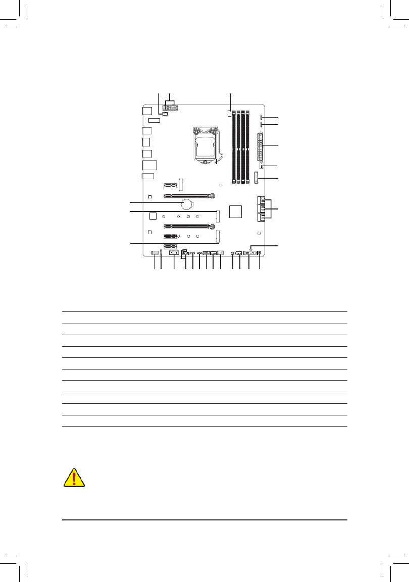
1-7 Internal Connectors
Readthefollowingguidelinesbeforeconnectingexternaldevices:
•First make sure your devices are compliant with the connectors you wish to connect.
•Before installing the devices, be sure to turn off the devices and your computer. Unplug the power
cord from the power outlet to prevent damage to the devices.
•After installing the device and before turning on the computer, make sure the device cable has
been securely attached to the connector on the motherboard.
1) ATX_12V_2X2/ATX_12V_2X4
2) ATX
3) CPU_FAN
4) SYS_FAN1/2/3/4
5) D_LED1/D_LED2
6) LED_C1/LED_C2
7) SATA3 0/1/2/3/4/5
8) M2A_SB/M2M_SB
9) F_PANEL
10) F_AUDIO
11) SPDIF_O
12) F_U32
13) F_USB
14) THB_C1/THB_C2
15) COM
16) SPI_TPM
17) QFLASH_PLUS
18) CLR_CMOS
19) BAT
20) CPU/DRAM/VGA/BOOT
920
4
2
7
12
165
10 11
14
14
18
19
15 13 4
3
8
4
5
6
6
8
17
- 12 -

3/4) CPU_FAN/SYS_FAN1/2/3/4 (Fan Headers)
All fan headers on this motherboard are 4-pin. Most fan headers possess a foolproof insertion design.
When connecting a fan cable, be sure to connect it in the correct orientation (the black connector wire is
the ground wire). The speed control function requires the use of a fan with fan speed control design. For
optimum heat dissipation, it is recommended that a system fan be installed inside the chassis.
•Be sure to connect fan cables to the fan headers to prevent your CPU and system from
overheating. Overheating may result in damage to the CPU or the system may hang.
•Thesefanheadersarenotcongurationjumperblocks.Donotplaceajumpercapontheheaders.
SYS_FAN1
1 1
CPU_FAN/SYS_FAN2 SYS_FAN3/SYS_FAN4
1
PinNo. Denition
1GND
2 Voltage Speed Control
3 Sense
4 PWM Speed Control
5) D_LED1/D_LED2 (Digital LED Strip Headers)
The headers can be used to connect a standard 5050 addressable LED strip, with maximum power rating
of 5A (5V) and maximum number of 1000 LEDs.
PinNo. Denition
1 V (5V)
2 D
3NoPin
4 G
11
D_LED1 D_LED2
Connect your addressable LED strip to the header. The power pin
(marked with a triangle on the plug) of the LED strip must be connected
to Pin 1 of the addressable LED strip header. Incorrect connection may
lead to the damage of the LED strip.
6) LED_C1/LED_C2 (RGB LED Strip Headers)
Theheaderscanbeusedtoconnectastandard5050RGBLEDstrip(12V/G/R/B),withmaximumpower
rating of 2A (12V) and maximum length of 2m.
PinNo. Denition
1 12V
2 G
3R
4 B
Before installing the devices, be sure to turn off the devices and your computer. Unplug the power
cord from the power outlet to prevent damage to the devices.
1
ConnectyourRGBLEDstriptotheheader.Thepowerpin(marked
with a triangle on the plug) of the LED strip must be connected to Pin
1 (12V) of this header. Incorrect connection may lead to the damage
of the LED strip.
Forhowtoturnon/offthelightsoftheLEDstrippleasevisitthe"UniqueFeatures"webpageof
GIGABYTE's website.
LED_C2
1
LED_C1
RGBLEDStrip
1
12V
Addressable LED
Strip
1
- 14 -

7) SATA3 0/1/2/3/4/5 (SATA 6Gb/s Connectors)
The SATA connectors conform to SATA 6Gb/s standard and are compatible with SATA 3Gb/s and SATA
1.5Gb/s standard. Each SATA connector supports a single SATA device. The Intel®ChipsetsupportsRAID0,
RAID1,RAID5,andRAID10.RefertoChapter3,"ConguringaRAIDSet,"forinstructionsonconguring
aRAIDarray.
PinNo. Denition
1GND
2 TXP
3TXN
4GND
5RXN
6RXP
7GND
Toenablehot-pluggingfortheSATAports,refertoChapter2,"BIOSSetup,""Settings\IOPorts\
SATAAndRSTConguration,"formoreinformation.
1
1
SATA3 531
420
7
7
8) M2A_SB/M2M_SB (M.2 Socket 3 Connectors)
TheM.2connectorssupportM.2SATASSDsorM.2PCIeSSDsandsupportRAIDconguration.Please
notethatanM.2PCIeSSDcannotbeusedtocreateaRAIDseteitherwithanM.2SATASSDoraSATA
harddrive.TocreateaRAIDarraywithanM.2PCIeSSD,youmustsetupthecongurationinUEFIBIOS
mode.RefertoChapter3,"ConguringaRAIDSet,"forinstructionsonconguringaRAIDarray.
SB_
80110 60
M2A_SB
_
B
BS_
B
80 60
M2M_SB
42
42
Follow the steps below to correctly install an M.2 SSD in the M.2 connector.
Step 1:
Use a screw driver to unfasten the screw and standoff from the motherboard. Locate the proper mounting
holefortheM.2SSDtobeinstalledandthenscrewthestandoffrst.
Step 2:
Slide the M.2 SSD into the connector at an angle.
Step 3:
Press the M.2 SSD down and then secure it with the screw.
- 15 -

•M2A_SB:
SATA3 0 SATA3 1 SATA3 2 SATA3 3 SATA3 4 SATA3 5
M.2 SATA SSD araaaa
M.2 PCIe SSD
aaaaaa
NoM.2SSDInstalled aaaaaa
a r: Available, :Notavailable
Connector
Type of
M.2 SSD
Installation Notices for the M.2 and SATA Connectors:
The availability of the SATA connectors may be affected by the type of device installed in the M.2 sockets. The
M2A_SBconnectorsharesbandwidthwiththeSATA31connector.Refertothefollowingtablesfordetails.
•M2M_SB:
SATA3 0 SATA3 1 SATA3 2 SATA3 3 SATA3 4 SATA3 5
M.2 PCIe SSD *
aaaaaa
NoM.2SSDInstalled aaaaaa
a r: Available, :Notavailable
* The M2M_SB connector supports only PCIe SSDs.
Connector
Type of
M.2 SSD
- 16 -

The front panel design may differ by chassis. A front panel module mainly consists of power switch, reset
switch, power LED, hard drive activity LED, speaker and etc. When connecting your chassis front panel
module to this header, make sure the wire assignments and the pin assignments are matched correctly.
9) F_PANEL (Front Panel Header)
Connect the power switch, reset switch, speaker, chassis intrusion switch/sensor and system status indicator
onthechassistothisheaderaccordingtothepinassignmentsbelow.Notethepositiveandnegativepins
before connecting the cables.
System Status LED
S0 On
S3/S4/S5 Off
•PW(PowerSwitch,Red):
Connects to the power switch on the chassis front panel. You may
congure the way to turn off your system using the power switch
(refertoChapter2,"BIOSSetup,""Settings\PlatformPower,"formore
information).
•SPEAK (Speaker, Orange):
Connects to the speaker on the chassis front panel. The system reports
system startup status by issuing a beep code. One single short beep
•PLED/PWR_LED (Power LED, Yellow/Purple):
Connects to the power status indicator
on the chassis front panel. The LED is on
when the system is operating. The LED is
off when the system is in S3/S4 sleep state
or powered off (S5).
will be heard if no problem is detected at system startup.
•HD (Hard Drive Activity LED, Blue):
Connects to the hard drive activity LED on the chassis front panel. The LED is on when the hard drive
is reading or writing data.
•RES (ResetSwitch,Green):
Connects to the reset switch on the chassis front panel. Press the reset switch to restart the computer
ifthecomputerfreezesandfailstoperformanormalrestart.
•CI (Chassis Intrusion Header, Gray):
Connects to the chassis intrusion switch/sensor on the chassis that can detect if the chassis cover has
been removed. This function requires a chassis with a chassis intrusion switch/sensor.
•NC (Orange):NoConnection.
Power LED
1
2
19
20
CI-
CI+
PWR_LED-
PWR_LED+
PLED-
PW-
SPEAK+
SPEAK-
PLED+
PW+
Power LED
HD-
RES+
HD+
RES-
Hard Drive
Activity LED
Reset
Switch Chassis Intrusion
Header
Power Switch Speaker
PWR_LED-
NC
NC
10) F_AUDIO (Front Panel Audio Header)
ThefrontpanelaudioheadersupportsHighDenitionaudio(HD).Youmayconnectyourchassisfront
panel audio module to this header. Make sure the wire assignments of the module connector match the
pin assignments of the motherboard header. Incorrect connection between the module connector and the
motherboard header will make the device unable to work or even damage it.
Some chassis provide a front panel audio module that has separated connectors on each wire instead
of a single plug. For information about connecting the front panel audio module that has different wire
assignments, please contact the chassis manufacturer.
9 1
10 2
PinNo. Denition PinNo. Denition
1 MIC2_L 6 Sense
2 7GND FAUDIO_JD
3 8MIC2_R NoPin
4 9NC LINE2_L
5 10 SenseLINE2_R
- 17 -

11) SPDIF_O (S/PDIF Out Header)
This header supports digital S/PDIF Out and connects a S/PDIF digital audio cable (provided by expansion
cards) for digital audio output from your motherboard to certain expansion cards like graphics cards and
sound cards. For example, some graphics cards may require you to use a S/PDIF digital audio cable for
digital audio output from your motherboard to your graphics card if you wish to connect an HDMI display
to the graphics card and have digital audio output from the HDMI display at the same time. For information
about connecting the S/PDIF digital audio cable, carefully read the manual for your expansion card.
PinNo. Denition
1 5VDUAL
2NoPin
3 SPDIFO
4GND
1
PinNo. Denition PinNo. Denition PinNo. Denition
1 VBUS 8 D1- 15 SSTX2-
2 9 D1+ 16SSRX1- GND
3 10 17SSRX1+ NC SSRX2+
4 D2+ 18GND 11 SSRX2-
5 SSTX1- 12 D2- 19 VBUS
6 SSTX1+ 13 20GND NoPin
7 14 SSTX2+GND
12) F_U32 (USB 3.2 Gen 1 Header)
TheheaderconformstoUSB3.2Gen1andUSB2.0specicationandcanprovidetwoUSBports.For
purchasingtheoptional3.5"frontpanelthatprovidestwoUSB3.2Gen1ports,pleasecontactthelocal
dealer.
10
20 1
11
13) F_USB (USB 2.0/1.1 Header)
TheheaderconformstoUSB2.0/1.1specication.EachUSBheadercanprovidetwoUSBportsviaan
optional USB bracket. For purchasing the optional USB bracket, please contact the local dealer.
PinNo. Denition PinNo. Denition
1 Power (5V) 6 USB DY+
2 Power (5V) 7 GND
3 USB DX- 8 GND
4 USB DY- 9 NoPin
5 USB DX+ 10 NC
•Do not plug the IEEE 1394 bracket (2x5-pin) cable into the USB 2.0/1.1 header.
•Prior to installing the USB bracket, be sure to turn off your computer and unplug the power cord
from the power outlet to prevent damage to the USB bracket.
10
9
2
1
- 18 -

14) THB_C1/THB_C2 (Thunderbolt™ Add-in Card Connectors)
The connectors are used to connect to a GIGABYTE Thunderbolt™ add-in card
Supports a Thunderbolt™ add-in card.
10
9
2
1
15) COM (Serial Port Header)
The COM header can provide one serial port via an optional COM port cable. For purchasing the optional
COM port cable, please contact the local dealer.
PinNo. Denition PinNo. Denition
1 6NDCD- NDSR-
2 7NSIN NRTS-
3 8NSOUT NCTS-
4 9NDTR- NRI-
5 10GND NoPin
12
11
2
1
16) SPI_TPM (Trusted Platform Module Header)
You may connect an SPI TPM (Trusted Platform Module) to this header.
PinNo. Denition PinNo. Denition
1Data Output 7Chip Select
2Power (3.3V) 8GND
3NoPin 9IRQ
4NC 10 NC
5Data Input 11 NC
6CLK 12 RST
17) QFLASH_PLUS (Q-Flash Plus Button)
Q-Flash Plus allows you to update the BIOS when your system is off (S5 shutdown state). Save the latest
BIOSonaUSBthumbdriveandplugitintothededicatedport,andthenyoucannowashtheBIOS
automaticallybysimplypressingtheQ-FlashPlusbutton.TheQFLEDwillashwhentheBIOSmatching
andashingactivitiesstartandwillstopashingwhenthemainBIOSashingiscomplete.
ForhowtouseQ-FlashPluspleasevisitthe"UniqueFeatures"webpageofGIGABYTE'swebsite.
QFLASH_PLUS
QFLED
S
SF
B_
1
1THB_C2
THB_C1
- 19 -

19) BAT (Battery)
Thebatteryprovidespowertokeepthevalues(suchasBIOScongurations,date,andtimeinformation)
intheCMOSwhenthecomputeristurnedoff.Replacethebatterywhenthebatteryvoltagedropstoalow
level, or the CMOS values may not be accurate or may be lost.
You may clear the CMOS values by removing the battery:
1. Turn off your computer and unplug the power cord.
2. Gently remove the battery from the battery holder and wait for one minute. (Or use a metal
object like a screwdriver to touch the positive and negative terminals of the battery holder,
making them short for 5 seconds.)
3. Replacethebattery.
4. Plug in the power cord and restart your computer.
•Always turn off your computer and unplug the power cord before replacing the battery.
•Replacethebatterywithanequivalentone.Damagetoyourdevicesmayoccurifthebatteryis
replaced with an incorrect model.
•Contact the place of purchase or local dealer if you are not able to replace the battery by yourself
or uncertain about the battery model.
•When installing the battery, note the orientation of the positive side (+) and the negative side (-)
of the battery (the positive side should face up).
•Used batteries must be handled in accordance with local environmental regulations.
20) CPU/DRAM/VGA/BOOT (Status LEDs)
The status LEDs show whether the CPU, memory, graphics card, and operating system are working
properlyaftersystempower-on.IftheCPU/DRAM/VGALEDison,thatmeansthecorrespondingdevice
is not working normally; if the BOOT LED is on, that means you haven't entered the operating system yet.
CPU: CPU status LED
DRAM: Memory status LED
VGA: Graphics card status LED
BOOT: Operating system status LED
S_
18) CLR_CMOS (Clear CMOS Jumper)
UsethisjumpertocleartheBIOScongurationandresettheCMOSvaluestofactorydefaults.Toclear
the CMOS values, use a metal object like a screwdriver to touch the two pins for a few seconds.
•Always turn off your computer and unplug the power cord from the power outlet before clearing
the CMOS values.
•Aftersystemrestart,gotoBIOSSetuptoloadfactorydefaults(selectLoadOptimizedDefaults)or
manuallyconguretheBIOSsettings(refertoChapter2,"BIOSSetup,"forBIOScongurations).
Open:Normal
Short: Clear CMOS Values
- 20 -
CPU DRAM
VGA BOOT

BIOS (Basic Input and Output System) records hardware parameters of the system in the CMOS on the
motherboard. Its major functions include conducting the Power-On Self-Test (POST) during system startup,
saving system parameters and loading operating system, etc. BIOS includes a BIOS Setup program that allows
theusertomodifybasicsystemcongurationsettingsortoactivatecertainsystemfeatures.
When the power is turned off, the battery on the motherboard supplies the necessary power to the CMOS to
keepthecongurationvaluesintheCMOS.
To access the BIOS Setup program, press the <Delete> key during the POST when the power is turned on.
To upgrade the BIOS, use either the GIGABYTE Q-Flash or @BIOS utility.
•Q-Flash allows the user to quickly and easily upgrade or back up BIOS without entering the operating system.
•@BIOS is a Windows-based utility that searches and downloads the latest version of BIOS from the Internet
and updates the BIOS.
Chapter 2 BIOS Setup
•BecauseBIOSashingispotentiallyrisky,ifyoudonotencounterproblemsusingthecurrentversionofBIOS,
itisrecommendedthatyounotashtheBIOS.ToashtheBIOS,doitwithcaution.InadequateBIOSashing
may result in system malfunction.
•It is recommended that you not alter the default settings (unless you need to) to prevent system instability or other
unexpected results. Inadequately altering the settings may result in system's failure to boot. If this occurs, try to
cleartheCMOSvaluesandresettheboardtodefaultvalues.(Refertothe"LoadOptimizedDefaults"sectionin
this chapter or introductions of the battery/clear CMOS jumper in Chapter 1 for how to clear the CMOS values.)
2-1 Startup Screen
The following startup Logo screen will appear when the computer boots.
•When the system is not stable as usual, select the item to set your system to its defaults.Load Optimized Defaults
•The BIOS Setup menus described in this chapter are for reference only and may differ by BIOS version.
Function Keys
There are two different BIOS modes as follows and you can use the <F2> key to switch between the two modes.
Easy Mode allows users to quickly view their current system information or to make adjustments for optimum
performance.InEasyMode,youcanuseyourmousetomovethroughcongurationitems.TheAdvancedMode
provides detailed BIOS settings. You can press the arrow keys on your keyboard to move among the items
and press <Enter> to accept or enter a sub-menu. Or you can use your mouse to select the item you want.
- 21 -

2-2 The Main Menu
Hardware
Information
Option Description Current Settings
Setup Menus
Conguration
Items
System
Time
Quick Access Bar allows you to quickly move to
the General Help, Easy Mode, Smart Fan 5, or
Q-Flash screen.
Advanced Mode Function Keys
<f><g> Move the selection bar to select a setup menu
<h><i>Movetheselectionbartoselectancongurationitemonamenu
<Enter>/Double Click Execute command or enter a menu
<+ >/<Page Up> Increase the numeric value or make changes
<->/<Page Down> Decrease the numeric value or make changes
<F1> Show descriptions of the function keys
<F2> Switch to Easy Mode
<F3> SavethecurrentBIOSsettingstoaprole
<F4> LoadtheBIOSsettingsfromaprolecreatedbefore
<F5> RestorethepreviousBIOSsettingsforthecurrentsubmenus
<F6> Display the Smart Fan 5 screen
<F7> LoadtheOptimizedBIOSdefaultsettingsforthecurrentsubmenus
<F8> Access the Q-Flash utility
<F10> Save all the changes and exit the BIOS Setup program
<F11> Switch to the Favorites submenu
<F12> Capture the current screen as an image and save it to your USB drive
<Insert> Add or remove a favorite option
<Ctrl>+<S> Display information on the installed memory
<Esc> Main Menu: Exit the BIOS Setup program
Submenus: Exit current submenu
- 22 -

2-3 Favorites (F11)
Set your frequently used options as your favorites and use the <F11> key to quickly switch to the page where
all of your favorite options are located. To add or remove a favorite option, go to its original page and press
<Insert>ontheoption.Theoptionismarkedwithastarsignifsetasa"favorite."
- 23 -

&FCLK Frequency for Early Power On
AllowsyoutosettheFCLKfrequency.Optionsare:Normal(800Mhz),1GHz,400MHz.(Default:1GHz)
&Hyper-Threading Technology
Allows you to determine whether to enable multi-threading technology when using an Intel® CPU that
supports this function. This feature only works for operating systems that support multi-processor mode.
AutoletstheBIOSautomaticallycongurethissetting.(Default:Auto)
&No. of CPU Cores Enabled
Allows you to select the number of CPU cores to enable in an Intel® multi-core CPU (the number of CPU
coresmayvarybyCPU).AutoletstheBIOSautomaticallycongurethissetting.(Default:Auto)
dPer Core HT Disable Setting
&HT Disable (Note)
AllowsyoudeterminewhethertodisabletheHTfeatureforeachCPUcore.Thisitemiscongurableonly
when Per Core HT Disable Setting is set to Manual. (Default: Disabled)
&VT-d
Enables or disables Intel®VirtualizationTechnologyforDirectedI/O.(Default:Enabled)
&Intel(R) Speed Shift Technology (Intel® Speed Shift Technology) (Note)
Enables or disables Intel® Speed Shift Technology. Enabling this feature allows the processor to ramp up
its operating frequency more quickly and then improves the system responsiveness. (Default: Enabled)
&CPU Thermal Monitor (Note)
Enables or disables Intel® Thermal Monitor function, a CPU overheating protection function. When enabled,
the CPU core frequency and voltage will be reduced when the CPU is overheated. lets the BIOS Auto
automaticallycongurethissetting.(Default:Auto)
&Ring to Core offset (Down Bin)
AllowsyoutodeterminewhethertodisabletheCPURingratioauto-downfunction.Auto lets the BIOS
automaticallycongurethissetting.(Default:Auto)
&CPU EIST Function (Note)
Enables or disables Enhanced Intel® Speed Step Technology (EIST). Depending on CPU loading, Intel®
EIST technology can dynamically and effectively lower the CPU voltage and core frequency to decrease
average power consumption and heat production. AutoletstheBIOSautomaticallycongurethissetting.
(Default: Auto)
&Race To Halt (RTH) (Note)/EnergyEfcientTurbo (Note)
Enables or disables the CPU power saving related settings.
&Voltage Optimization
Allowsyoutodeterminewhethertoenablevoltageoptimizationtoreducepowerconsumption.(Default:
Auto)
&Intel(R) Turbo Boost Technology (Note)
Allows you to determine whether to enable the Intel® CPU Turbo Boost technology. lets the BIOS Auto
automaticallycongurethissetting.(Default:Auto)
&CPU Flex Ratio Override
EnablesordisablestheCPUFlexRatio.ThemaximumCPUclockratiowillbebasedontheCPU Flex
Ratio Settings CPU Clock Ratio Auto value if is set to . (Default: Disabled)
&CPU Flex Ratio Settings
AllowsyoutosettheCPUFlexRatio.TheadjustablerangemayvarybyCPU.
(Note) ThisitemispresentonlywhenyouinstallaCPUthatsupportsthisfeature.Formoreinformationabout
Intel® CPUs' unique features, please visit Intel's website.
- 25 -

&Frequency Clipping TVB (Note)
Allows you to enable or disable automatic CPU frequency reduction initiated by Thermal Velocity Boost.
AutoletstheBIOSautomaticallycongurethissetting.(Default:Auto)
&Voltage reduction initiated TVB (Note)
Allows you to enable or disable automatic CPU voltage reduction initiated by Thermal Velocity Boost. Auto
letstheBIOSautomaticallycongurethissetting.(Default:Auto)
dActive Turbo Ratios
&Turbo Ratio (1-Core Active~10-Core Active)
Allows you to set the CPU Turbo ratios for different number of active cores. sets the CPU Turbo Auto
ratiosaccordingtotheCPUspecications.
Thisitemiscongurableonlywhen
Active Turbo Ratios is set
to
Enabled
.
(Default: Auto)
dC-States Control
&CPU Enhanced Halt (C1E)
Enables or disables Intel
®
CPU Enhanced Halt (C1E) function, a CPU power-saving function in system halt state.
When enabled, the CPU core frequency and voltage will be reduced during system halt state to decrease
power consumption. AutoletstheBIOSautomaticallycongurethissetting.Thisitemiscongurableonly
when is set to C-States Control Enabled. (Default: Auto)
&C3 State Support (Note)
Allows you to determine whether to let the CPU enter C3 mode in system halt state. When enabled, the
CPU core frequency and voltage will be reduced during system halt state to decrease power consumption.
The C3 state is a more enhanced power-saving state than C1. AutoletstheBIOSautomaticallycongure
thissetting.ThisitemiscongurableonlywhenC-States Control Enabled is set to . (Default: Auto)
&C6/C7 State Support (Note)
Allows you to determine whether to let the CPU enter C6/C7 mode in system halt state. When enabled, the
CPU core frequency and voltage will be reduced during system halt state to decrease power consumption.
The C6/C7 state is a more enhanced power-saving state than C3. AutoletstheBIOSautomaticallycongure
thissetting.ThisitemiscongurableonlywhenC-States Control Enabled is set to . (Default: Auto)
&C8 State Support (Note)
Allows you to determine whether to let the CPU enter C8 mode in system halt state. When enabled, the CPU
core frequency and voltage will be reduced during system halt state to decrease power consumption. The
C8 state is a more enhanced power-saving state than C6/C7. AutoletstheBIOSautomaticallycongure
thissetting.ThisitemiscongurableonlywhenC-States Control Enabled is set to . (Default: Auto)
&C10 State Support (Note)
Allows you to determine whether to let the CPU enter C10 mode in system halt state. When enabled, the
CPU core frequency and voltage will be reduced during system halt state to decrease power consumption.
The C10 state is a more enhanced power-saving state than C8. AutoletstheBIOSautomaticallycongure
thissetting.ThisitemiscongurableonlywhenC-States Control Enabled is set to . (Default: Auto)
&Package C State Limit (Note)
Allows you to specify the C-state limit for the processor. AutoletstheBIOSautomaticallycongurethis
setting.ThisitemiscongurableonlywhenC-States Control Enabled is set to . (Default: Auto)
(Note) ThisitemispresentonlywhenyouinstallaCPUthatsupportsthisfeature.Formoreinformationabout
Intel® CPUs' unique features, please visit Intel's website.
- 26 -

&Rank Interleaving
Enables or disables memory rank interleaving. allows the system to simultaneously access different Enabled
ranks of the memory to increase memory performance and stability. lets the BIOS automatically Auto
congurethissetting.(Default:Auto)
&Memory Boot Mode
Provides memory detection and training methods.
Auto LetstheBIOSautomaticallycongurethissetting.(Default)
Normal TheBIOSautomaticallyperformsmemorytraining.Pleasenotethatifthesystem
becomes unstable or unbootable, try to clear the CMOS values and reset the board
todefaultvalues.(Refertotheintroductionsofthebattery/clearCMOSjumperin
Chapter 1 for how to clear the CMOS values.)
Fast Skipmemorydetectionand traininginsomespeciccriteriaforfastermemory
boot.
Disable Fast Boot Detect and train memory at every single boot.
&Realtime Memory Timing
Allowsyoutone-tunememorytimingsaftertheBIOSstage.(Default:Auto)
&Memory Enhancement Settings
Providesseveralmemoryperformanceenhancementsettings:Auto,RelaxOC,EnhancedStability,Normal,
EnhancedPerformance,HighFrequency,HighDensity,andDDR-4500+.(Default:Auto)
&Memory Channel Detection Message
Allows you to determine whether to show an alert message when the memory is not installed in the optimal
memory channel. (Default: Enabled)
SPD Info
Displays information on the installed memory.
Memory Channels Timing
d Channels Standard Timing Control, Channels Advanced Timing Control, Channel Misc
Timing Control
Thesesectionsprovidememorytimingsettings.Note:Yoursystemmaybecomeunstableorfailtoboot
after you make changes on the memory timings. If this occurs, please reset the board to default values by
loadingoptimizeddefaultsorclearingtheCMOSvalues.
& Vcore Voltage Mode/SVID offset/BCLK Adaptive Voltage/CPU Graphics Voltage
(VAXG)/DRAM Voltage (CH A/B)/CPU VCCIO/CPU VCCIO2/CPU System Agent Voltage/
VCC Substained/VCCPLL/VCCPLL OC/VCCVTT/PCH Core
These items allow you to adjust the CPU Vcore and memory voltages.
Advanced Voltage Settings
ThissubmenuallowsyoutocongureLoad-LineCalibrationlevel,over-voltageprotectionlevel,andover-
current protection level.
- 28 -

2-5 Settings
Platform Power
&Platform Power Management
Enables or disables the Active State Power Management function (ASPM). (Default: Disabled)
&Power On By Keyboard
Allows the system to be turned on by a PS/2 keyboard wake-up event.
Note:Tousethisfunction,youneedanATXpowersupplyprovidingatleast1Aonthe+5VSBlead.
Disabled Disables this function. (Default)
Password Set a password with 1~5 characters to turn on the system.
Keyboard98 PressPOWERbuttonontheWindows98keyboardtoturnonthesystem.
Any Key Press any key to turn on the system.
&Power On Password
Set the password when is set to .Power On By Keyboard Password
Press <Enter> on this item and set a password with up to 5 characters and then press <Enter> to accept.
To turn on the system, enter the password and press <Enter>.
Note:Tocancelthepassword,press<Enter>onthisitem.Whenpromptedforthepassword,press<Enter>
again without entering the password to clear the password settings.
&Power On By Mouse
Allows the system to be turned on by a PS/2 mouse wake-up event.
Note:Tousethisfunction,youneedanATXpowersupplyprovidingatleast1Aonthe+5VSBlead.
Disabled Disables this function. (Default)
Move Move the mouse to turn on the system.
Double Click Double click on left button on the mouse to turn on the system.
&ErP
Determines whether to let the system consume least power in S5 (shutdown) state. (Default: Disabled)
Note:WhenthisitemissettoEnabled,thefollowingfunctionswillbecomeunavailable:ResumebyAlarm,
power on by mouse, and power on by keyboard.
&Soft-Off by PWR-BTTN
ConguresthewaytoturnoffthecomputerinMS-DOSmodeusingthepowerbutton.
Instant-Off Press the power button and then the system will be turned off instantly. (Default)
Delay 4 Sec. Press and hold the power button for 4 seconds to turn off the system. If the power
button is pressed for less than 4 seconds, the system will enter suspend mode.
- 29 -

&Resume by Alarm
Determines whether to power on the system at a desired time. (Default: Disabled)
If enabled, set the date and time as following:
Wakeupday:Turnonthesystemataspecictimeoneachdayoronaspecicdayinamonth.
Wake up hour/minute/second: Set the time at which the system will be powered on automatically.
Note:Whenusingthisfunction,avoidinadequateshutdownfromtheoperatingsystemorremovalofthe
AC power, or the settings may not be effective.
&Power Loading
Enables or disables dummy load. When the power supply is at low load, a self-protection will activate causing
it to shutdown or fail. If this occurs, please set to Enabled Auto. letstheBIOSautomaticallycongurethis
setting. (Default: Auto)
&RC6(Render Standby)
Allows you to determine whether to let the onboard graphics enter standby mode to decrease power
consumption. (Default: Enabled)
&AC BACK
Determines the state of the system after the return of power from an AC power loss.
Memory The system returns to its last known awake state upon the return of the AC power.
Always On The system is turned on upon the return of the AC power.
Always Off The system stays off upon the return of the AC power. (Default)
IO Ports
&Initial Display Output
SpeciestherstinitiationofthemonitordisplayfromtheinstalledPCIExpressgraphicscardortheonboard
graphics.
IGD Video(Note) Setstheonboardgraphicsastherstdisplay.
PCIe1Slot SetsthegraphicscardonthePCIEX16slotastherstdisplay.(Default)
PCIe2Slot SetsthegraphicscardonthePCIEX4slotastherstdisplay.
&Internal Graphics
Enables or disables the onboard graphics function. (Default: Auto)
&DVMT Pre-Allocated
Allowsyoutosettheonboardgraphicsmemorysize.Optionsare:32M~512M.(Default:64M)
&DVMT Total Gfx Mem
AllowsyoutoallocatetheDVMTmemorysizeoftheonboardgraphics.Optionsare:128M,256M,MAX.
(Default: 256M)
&Aperture Size
Allows you to set the maximum amount of system memory that can be allocated to the graphics card.
Options are: 128MB, 256MB, 512MB, 1024MB, and 2048MB. (Default: 256MB)
&PCIE Bifurcation Support
Allows you to determine how the bandwidth of the PCIEX16 slot is divided. Options: PCIE x16, PCIE x8/
x8, PCIE x8/x4/x4. (Default: Auto)
&OnBoard LAN Controller
EnablesordisablestheonboardLANfunction.(Default:Enabled)
Ifyouwishtoinstalla3rdpartyadd-innetworkcardinsteadofusingtheonboardLAN,setthisitemto
Disabled.
(Note) ThisitemispresentonlywhenyouinstallaCPUthatsupportsthisfeature.
- 30 -
Produktspecifikationer
| Varumärke: | Gigabyte |
| Kategori: | moderkort |
| Modell: | Z490 UD |
Behöver du hjälp?
Om du behöver hjälp med Gigabyte Z490 UD ställ en fråga nedan och andra användare kommer att svara dig
moderkort Gigabyte Manualer

10 Mars 2025
3 Mars 2025
3 Mars 2025
18 Februari 2025
11 Februari 2025
11 Februari 2025
11 Februari 2025
11 Februari 2025
11 Februari 2025
11 Februari 2025
moderkort Manualer
- moderkort Asus
- moderkort Sharkoon
- moderkort Asrock
- moderkort Supermicro
- moderkort Evga
- moderkort Intel
- moderkort MSI
- moderkort ECS
- moderkort NZXT
- moderkort Foxconn
- moderkort Advantech
- moderkort Elitegroup
- moderkort EPoX
- moderkort Biostar
Nyaste moderkort Manualer
8 April 2025
8 April 2025
3 April 2025
3 April 2025
3 April 2025
3 April 2025
2 April 2025
2 April 2025
1 April 2025
30 Mars 2025