Hanwha SNV-8081R Bruksanvisning
Hanwha
övervakningskamera
SNV-8081R
Läs gratis den bruksanvisning för Hanwha SNV-8081R (166 sidor) i kategorin övervakningskamera. Guiden har ansetts hjälpsam av 17 personer och har ett genomsnittsbetyg på 4.3 stjärnor baserat på 9 recensioner. Har du en fråga om Hanwha SNV-8081R eller vill du ställa frågor till andra användare av produkten? Ställ en fråga
Sida 1/166

SNO-8081R/SNV-8081R
NETWORK CAMERA
User Manual

Copyright
©2016 Hanwha Techwin
Co., Ltd. All rights reserved.
Trademark
Each of trademarks herein is registered. The name of this product and other trademarks mentioned in this manual are the registered trademark of their
respective company.
Restriction
Copyright of this document is reserved. Under no circumstances, this document shall be reproduced, distributed or changed, partially or wholly, without
formal authorization.
Disclaimer
Hanwha Techwin makes the best to verify the integrity and correctness of the contents in this document, but no formal guarantee shall be
provided. Use of this document and the subsequent results shall be entirely on the user’s own responsibility.
Hanwha Techwin reserves the
right to change the contents of this document without prior notice.
Design and specications are subject to change without prior notice.
The initial administrator ID is “admin” and the password should be set when logging in for the rst time.
Please change your password every three months to safely protect personal information and to prevent the damage of the information
theft.
Please, take note that it’s a user’s responsibility for the security and any other problems caused by mismanaging a password.
Network Camera
User Manual

English _3
● overview
important Safety inStructionS
1. Read these instructions.
2. Keep these instructions.
3. Heed all warnings.
4. Follow all instructions.
5. Do not use this apparatus near water.
6. Clean the contaminated area on the product surface with a soft, dry cloth or a damp
cloth.
(Do not use a detergent or cosmetic products that contain alcohol, solvents or
surfactants or oil constituents as they may deform or cause damage to the product.)
7. Do not block any ventilation openings, Install in accordance with the manufacturer’s
instructions.
8. Do not install near any heat sources such as radiators, heat registers, stoves, or other
apparatus (including amplifiers) that produce heat.
9. Do not defeat the safety purpose of the polarized or grounding-type plug. A polarized
plug has two blades with one wider than the other. A grounding type plug has two
blades and a third grounding prong. The wide blade or the third prong are provided for
your safety. If the provided plug does not fit into your outlet, consult an electrician for
replacement of the obsolete outlet.
10. Protect the power cord from being walked on or pinched particularly at plugs,
convenience receptacles, and the point where they exit from the apparatus.
11. Only use attachments/ accessories specified by the manufacturer.
12. Use only with the cart, stand, tripod, bracket, or table specified by
the manufacturer, or sold with the apparatus. When a cart is used,
use caution when moving the cart/apparatus combination to avoid
injury from tip-over.
13. Unplug this apparatus during lighting storms or when unused for
long periods of time.
14. Refer all servicing to qualified service personnel. Servicing is required when the
apparatus has been damaged in any way, such as power-supply cord or plug is
damaged, liquid has been spilled or objects have fallen into the apparatus, the apparatus
has been exposed to rain or moisture, does not operate normally, or has been dropped.
15. This product is intended to be supplied by a Listed Power Supply Unit marked “Class 2”
or “LPS” and rated from 24 Vac (50/60 Hz) 1.0 A or 12 Vdc, 1.0 A.
overview
overview
4_ overview
warninG
TO REDUCE THE RISK OF FIRE OR ELECTRIC SHOCK, DO NOT EXPOSE
THIS PRODUCT TO RAIN OR MOISTURE. DO NOT INSERT ANY METALLIC
OBJECT THROUGH THE VENTILATION GRILLS OR OTHER OPENNINGS
ON THE EQUIPMENT.
Apparatus shall not be exposed to dripping or splashing and that no objects
filled with liquids, such as vases, shall be placed on the apparatus.
To prevent injury, this apparatus must be securely attached to the Wall/ceiling
in accordance with the installation instructions.
caution
caution
riSK of eLectric SHocK.
Do not open
CAUTION : TO REDUCE THE RISK OF ELECTRIC SHOCK.
DO NOT REMOVE COVER (OR BACK).
NO USER SERVICEABLE PARTS INSIDE.
REFER SERVICING TO QUALIFIED SERVICE PERSONNEL.
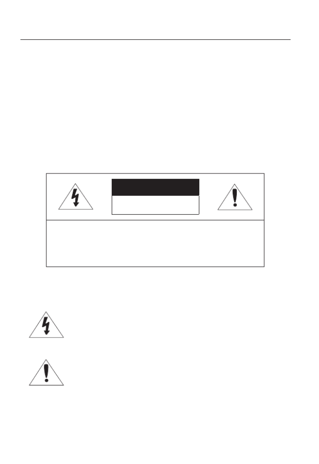
eXpLanation of GrapHicaL SymBoLS
The lightning flash with arrowhead symbol, within an
equilateral triangle, is intended to alert the user to the
presence of “dangerous voltage” within the product’s
enclosure that may be of sufficient magnitude to constitute a
risk of electric shock to persons.
The exclamation point within an equilateral triangle is intended
to alert the user to the presence of important operating
and maintenance (servicing) instructions in the literature
accompanying the product.

English _5
● OVERVIEW
Class construction
An apparatus with CLASS construction shall be connected to a MAINS
socket outlet with a protective earthing connection.
Battery
Batteries(battery pack or batteries installed) shall not be exposed to excessive
heat such as sunshine, fire or the like.
Disconnection Device
Disconnect the main plug from the apparatus, if it’s defected. And please call
a repair man in your location.
When used outside of the U.S., it may be used HAR code with fittings of
an approved agency is employed.
CAUTION
Risk of explosion if battery is replaced by an incorrect type.
Dispose of used batteries according to the instructions.
These servicing instructions are for use by qualified service personnel only.
To reduce the risk of electric shock do not perform any servicing other than
that contained in the operating instructions unless you are qualified to do so.
The CVBS out terminal of the product is provided for easier installation, and is
not recommended for monitoring purposes.
Please use the input power with just one camera and other devices must not
be connected.
The ITE is to be connected only to PoE networks without routing to the
outside plant.

overview
6_ overview
Please read the following recommended safety precautions carefully.
yDo not place this apparatus on an uneven surface.
yDo not install on a surface where it is exposed to direct sunlight, near
heating equipment or heavy cold area.
yDo not place this apparatus near conductive material.
yDo not attempt to service this apparatus yourself.
yDo not place a glass of water on the product.
yDo not install near any magnetic sources.
yDo not block any ventilation openings.
yDo not place heavy items on the product.
User’s Manual is a guidance book for how to use the products.
The meaning of the symbols are shown below.
yReference : In case of providing information for helping of product’s usages
yNotice : If there’s any possibility to occur any damages for the goods and
human caused by not following the instruction
Please read this manual for the safety before using of goods and keep it in
the safe place.

overview
10_ overview
recommenDeD pc SpecificationS
•CPU : Intel Core i5 compatible or higher
Intel Core i7 2.8 GHz or higher (when H.265 codec is used)
`Web Plug-in is optimized to SSE 4.1 Instruction Set.
•Resolution : 1280X1024 pixels or higher (32 bit color)
`If Mode is changed, the system is rebooted.
•Maximum resolution : 5M Mode + LDC ON : 15fps
2M Mode + LDC ON : 30fps
5M Mode + LDC ON + Hallway ON : 10fps
2M Mode + LDC ON + Hallway ON : 30fps
•RAM : 2GB or higher
•Supported OS : Windows XP / VISTA / 7 / 8 / 8.1, MAC OS X 10.7 ~ 10.10
•Supported Browser : Microsoft Internet Explorer (Ver. 8 ~ 11),
Mozilla Firefox (Ver. 9 ~ 35), Google Chrome (Ver. 15 ~ 40),
Apple Safari (Ver. 8.0.2(Mac OS X 10.10), 7.0.6(Mac OS X 10.9), 6.0.2 (Mac OS X 10.8,
10.7 only), 5.1.7) ※ Mac OS X only
`Windows 8 is supported only in the Desktop mode.
`Neither a beta test version unlike the version released in the company website nor the developer version will
be supported.
`For IPv6 connection, Window 7 or higher is recommended.
`For Mac OS X, only the Safari browser is supported.
`For all browsers, it is limited to a version that supports the web plug-in (Active X or NPAPI) function.
•VGA : PCIe 256MB GDDR3 video graphics card or higher
J
`If the driver of the video graphic adapter is not installed properly or is not the latest version, the
video may not be played properly.
`For a multi-monitoring system involving at least 2 monitors, the playback performance can be
deteriorated depending on the system.
English _11
● overview
recommenDeD micro SD/SDHc/SDXc memory carD
SpecificationS
•Recommended capacity : 4GB ~ 128GB
•For your camera, we recommend you use a memory card from the following manufacturers:
Micro SD/SDHC/SDXC Memory Card : Sandisk, Transcend
•For the framerate below 30 fps, it is recommended to use the specification memory card
of Class 6 or higher.
•For the framerate over 31 fps, it is recommended to use the specification memory card of
Class 10 UHS or higher.
naS recommenDeD SpecS
•Recommended capacity : 200GB or higher is recommended.
•Simultaneous access : One unit of NAS can accept a maximum of sixteen camera
accesses.
•For this camera, you are recommended to use a NAS with the following manufacturer’s
specs.
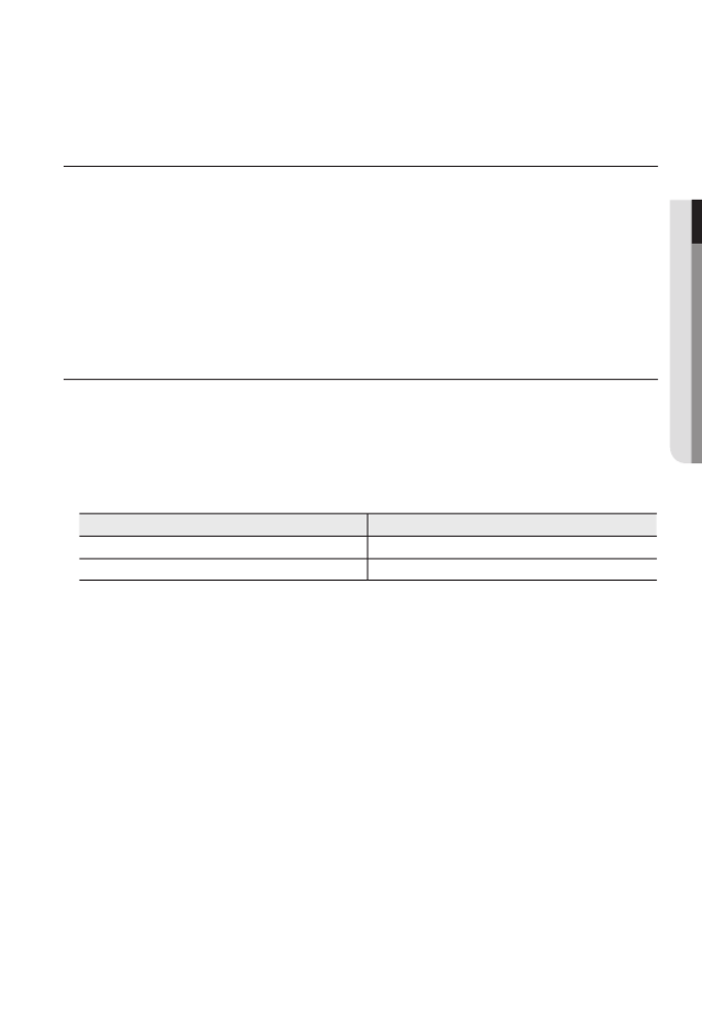
Recommended products Available sizes
Netgear NAS A maximum of 16 cameras can access simultaneously.
Synology NAS A maximum of 16 cameras can access simultaneously.
J
`When you use Netgear’s NAS equipment, do not allocate the capacity for use.
`If you use NAS equipment for purposes other than video saving, the number of accessible
cameras may be reduced.
overview
12_ overview
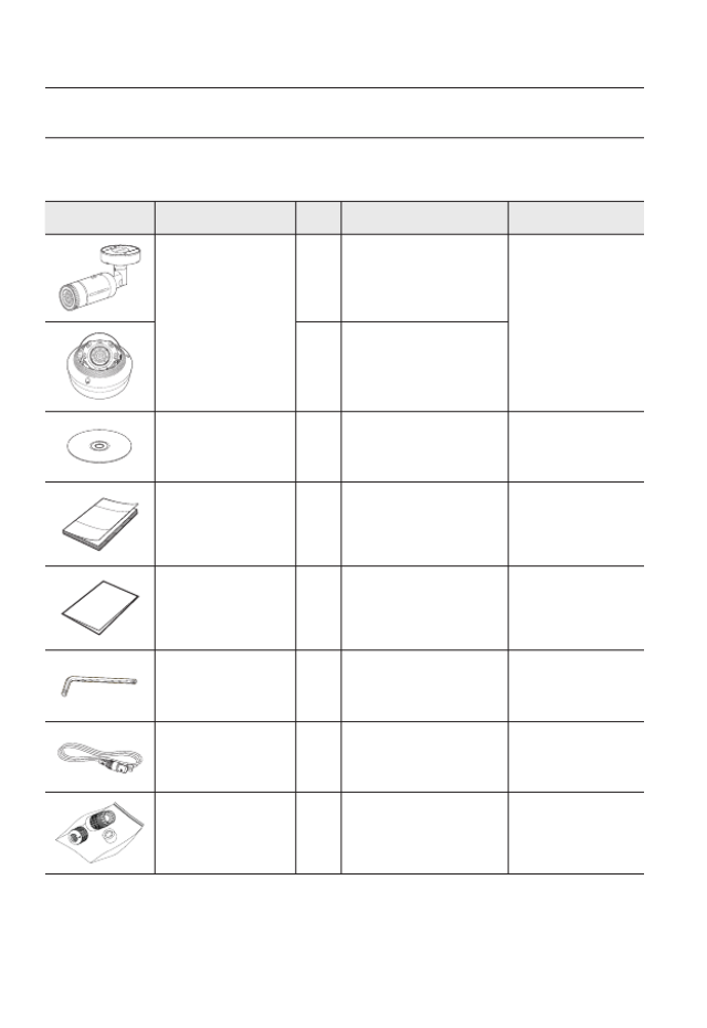
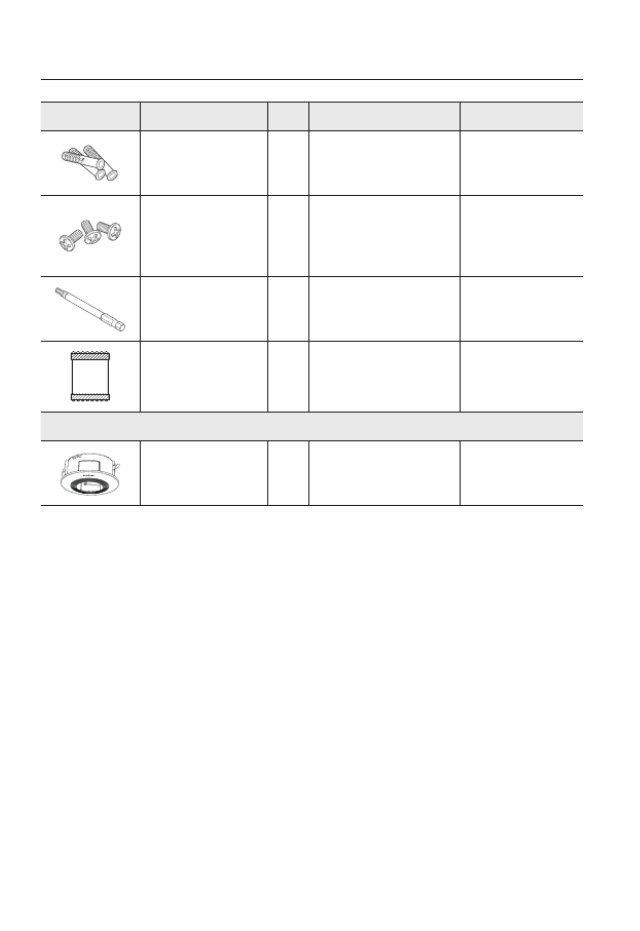
wHat’S incLuDeD
Please check if your camera and accessories are all included in the product package.
(As for each sales country, accessories are not the same.)
Appearance Item Name
Quantity
Description Model Name
Camera
1
SNO-8081R or
SNV-8081R
1
Instruction book,
Installer S/W CD 1SNO-8081R/
SNV-8081R
Quick Guide
(Optional) 1SNO-8081R/
SNV-8081R
Warranty card
(Optional) 1SNO-8081R/
SNV-8081R
L Wrench
1
Used to control the direction of
the camera / Used to remove and
replace the dome cover
SNO-8081R/
SNV-8081R
Cable for the testing
monitor 1
Used to test the camera
connection to a portable display
device
SNO-8081R/
SNV-8081R
RJ45 waterproof accessory
1
Used to install in humid places
SNO-8081R
English _13
● overview
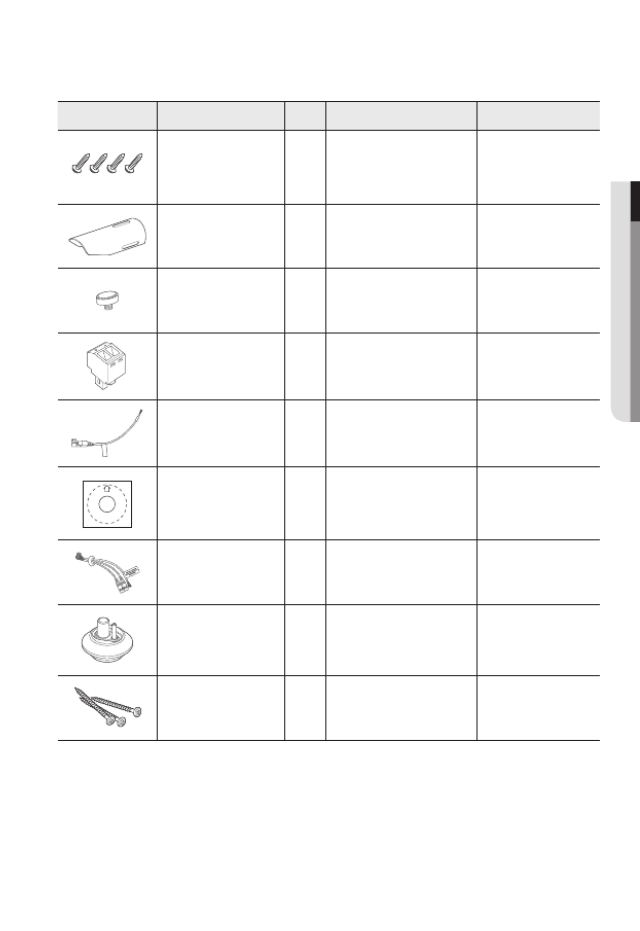
Appearance Item Name
Quantity
Description Model Name
Tapping Screw 4
Used for installation on the wall
or ceiling
SNO-8081R
Sunshield 1 It protects the camera from the
direct sunlight.
SNO-8081R
Sunshield Hold 1 It fixes the sunshield with the
camera.
SNO-8081R
Power Terminal Block Plugged in the power plug1SNV-8081R
CAUTION: Be w are of the Rated Voltage and Po larit y
of the power connec tion.
Power Cable
1
Used to plug into the power port
SNV-8081R
Template
1
Product installation guide
SNV-8081R
Audio/alarm cable
1
Used to connect with the
audio and alarm port
SNV-8081R
Cable bush 1 Used to connect the LAN cable
with a diameter of Ø7~8.5. SNV-8081R
Tapping Screw
3
Used for installation on the
wall or ceiling
SNV-8081R
overview
14_ overview
Appearance Item Name
Quantity
Description Model Name
Plastic Anchor
3
For fixing a screw,
Inserted in a hole
(reinforced anchoring force)
SNV-8081R
Machine Screws 3
Used for assembling the dome
case when installing the product
on the pipe, wall mount, etc. or
blocking a hole.
SNV-8081R
Drill bit 1
Used for dome cover
disassembly, assembly and
camera installation.
SNV-8081R
Card-type moisture
absorbent
1
Attached when installed.
SNV-8081R
Options (not included)
Indoor Buried Housing Housing for installing indoor
buried type cameras SNV-8081R
English _15
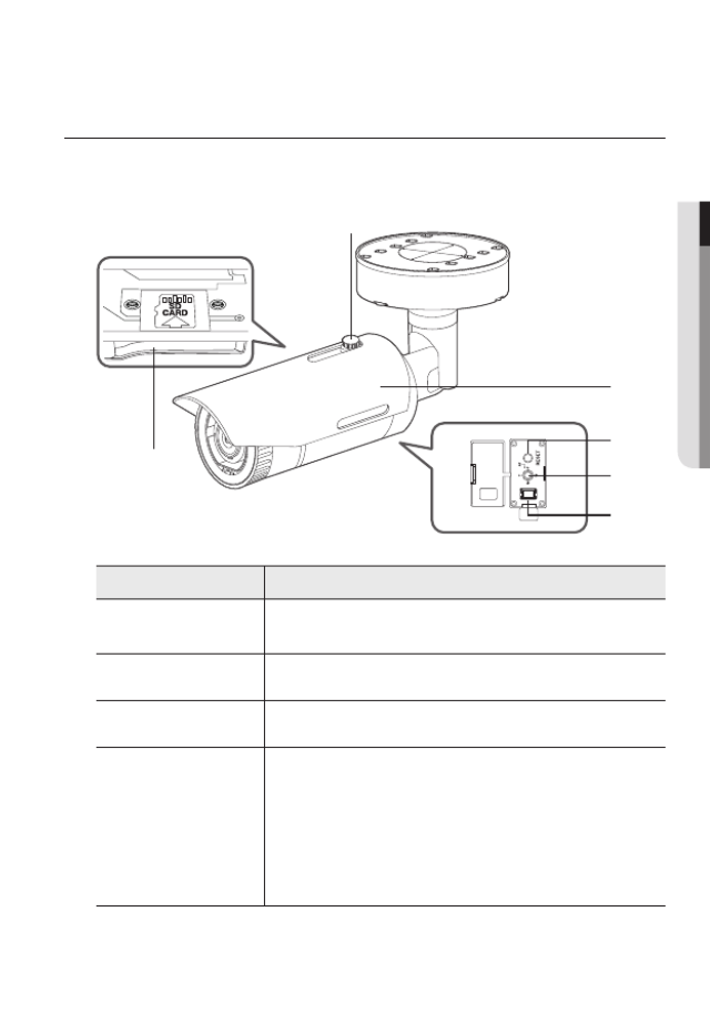
● OVERVIEW
AT A GLANCE (SNO-8081R)
Appearance
Item Description
a
Micro SD card slot (Internal space of the product) This is a slot in which you can insert a Micro
SD card.
b
Sunshield Hold It fixes the sunshield with the camera.
c
Sunshield It protects the camera from the direct sunlight.
d
Reset Button
The button restores all camera settings to the factory default.
Press and hold for about 5 seconds to reboot the system.
J If you reset the camera, the network settings will be adjusted so that
DHCP can be enabled. If there is no DHCP server in the network, you
must run the IP Installer program to change the basic network settings
such as IP address, Subnet mask, Gateway, etc., before you can
connect to the network.
d
e
c
f
a
b

overview
16_ overview
Item Description
e
Zoom/Focus Control
Button
T Zoom in (Tele)
W Zoom out (Wide)
N Focusing on a near object (Near)
F Focusing on a far object (Far)
Focus Control Press this button for automatic focus control.
f
Test Monitor Out Output port for test monitoring the video output. Use the test monitor cable
to connect to a mobile display and check the test video.
M
`Wipe out a dirty surface of the lens softly with a lens tissue or cloth to which you have applied
ethanol.
English _17
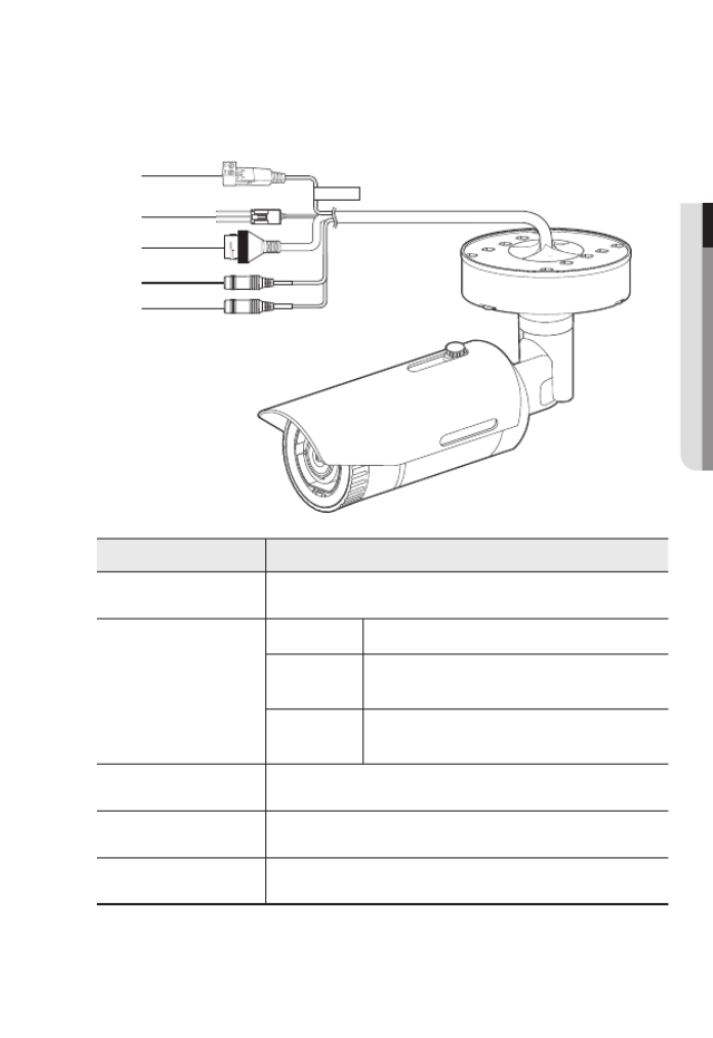
● OVERVIEW
Components
Item Description
a
Power Port Used to plug the power cable.
b
Alarm I/O Port
ARM-OUT Used to connect the alarm output signal.
GND These are common ports to connect alarm input/output
signals.
ARM-IN Used to connect the alarm input sensor or external day/
night sensor.
c
Network Port Used to connect the PoE or Ethernet cable for network connection.
d
Audio Out Jack Used to connect to speakers.
e
Audio In Jack Used to connect to a microphone.
CAUTIO N:Be ware of the
Rated Voltag e and Po larity
of the power co nnection.
a
b
c
d
e
overview
18_ overview
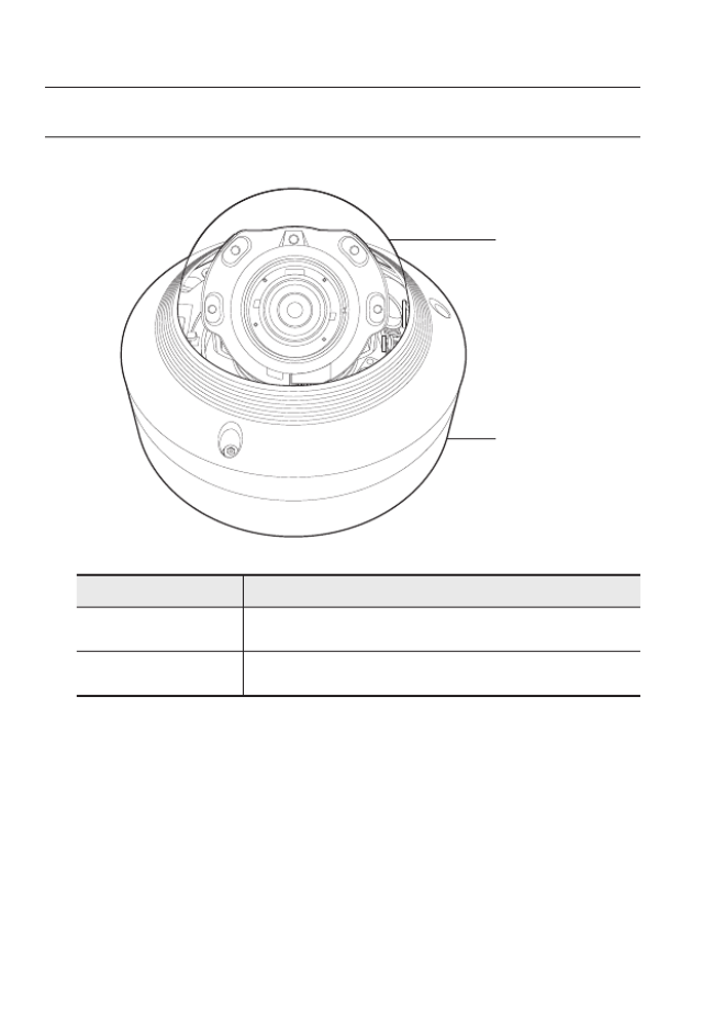
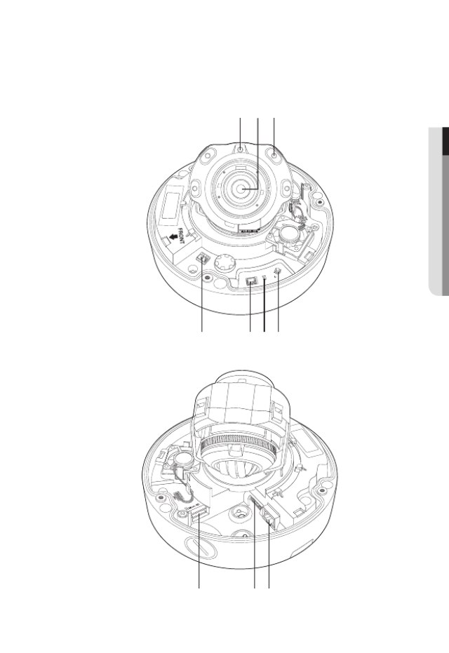
AT A GLANCE (SNV-8081R)
Appearance
Item Description
a
Dome cover Case cover used to protect the lens and the main unit.
b
Camera Case Housing part that covers the camera body.
a
b
English _19
● OVERVIEW
Components
AC 24V / DC 12V
RESET
VID EO
F
W
AF
T
N
+ -
a cb
d efg
h ji

overview
20_ overview
Item Description
a
Illumination Sensor Detects incoming light to control the IR LED.
b
Lens Lens for the camera.
c
IR LED These infrared LED’s are controlled by the illumination sensor.
d
Power Port Port for power terminal block.
e
Test Monitor Out Output port for test monitoring the video output. Use the test monitor cable
to connect to a mobile display and check the test video.
f
Reset Button
The button restores all camera settings to the factory default.
Press and hold for about 5 seconds to reboot the system.
J If you reset the camera, the network settings will be adjusted so that
DHCP can be enabled. If there is no DHCP server in the network, you
must run the IP Installer program to change the basic network settings
such as IP address, Subnet mask, Gateway, etc., before you can
connect to the network.
g
Zoom/Focus Control
Button
T Zoom in (Tele)
W Zoom out (Wide)
N Focusing on a near object (Near)
F Focusing on a far object (Far)
Focus Control Press this button for automatic focus control.
h
Micro SD Memory
Card Compartment Compartment for the Micro SD memory card.
i
Audio and alarm
cable port
Plug in the audio and alarm cable to this port to connect with external alarm
device/microphone/speaker.
j
Network Port Used to connect the PoE or Ethernet cable for network connection.
English _21
● INSTALLATION & CONNECTION
INSTALLATION (SNO-8081R)
J
`This camera is waterproof and in compliance with the IP66 spec, but the jack connected to the
external cable is not. You are recommended to install this product below the edge of eaves to
prevent the cable from being externally exposed.
Precautions before installation
Ensure you read out the following instructions before installing the camera:
• It must be installed on the area (ceiling or wall) that can withstand 5 times the weight
of the camera including the installation bracket.
• Stuck-in or peeled-off cables can cause damage to the product or a fire.
• For safety purposes, keep anyone else away from the installation site.
And put aside personal belongings from the site, just in case.
Installation
1. Fix the Bottom cover using the 4 tapping
screws provided.
installation & connection
installation & connection
22_ installation & connection
2. Hang the safety cable up on a hook that looks
like an arrow in the Bottom cover.
3. Connect the appropriate cables with camera
terminals.
4. Tighten the 3 screws on the Top cover using
the L wrench provided.
5. Adjust the camera direction using the L
wrench provided.
J
`When you adjust the camera position using a
bracket, please loosen the bracket screw, adjust
the camera, and tighten it. If you attempt to adjust
it forcibly while the screw is tight, it may result in
a scratch or other problems.
English _23
● INSTALLATION & CONNECTION
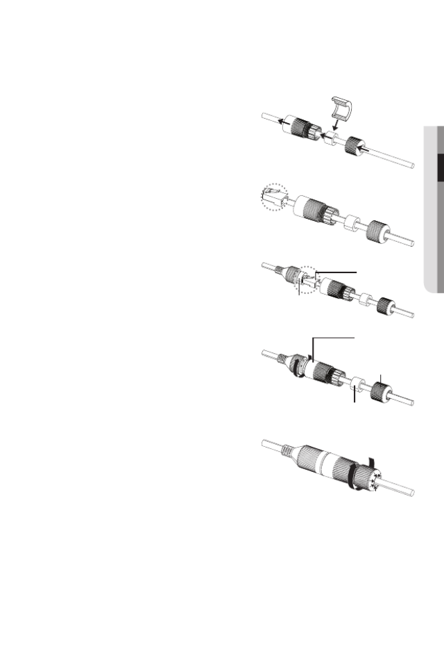
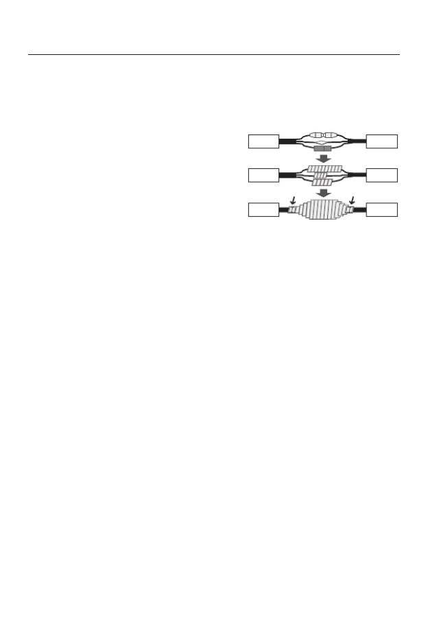
How to connect the RJ45 waterproof cable to a LAN cable
1. Insert it through the arrow direction.
2. Connect the LAN connector (male) to the
cable.
3. Connect the RJ45 modular jack (female) to
the RJ45 connector (male).
J
`Please, keep each of the parts separated.
4. Assemble by rotating the RJ45 modular
jack (female) and the RJ45 protection cover
clockwise (Follow the arrow).
5. Assemble by rotating RJ45 protection cover
and back cover clockwise (Follow the arrow).
When the back cover is assembled, the cable
waterproof gasket is tightly attached to the
cable to make it waterproof.
J
`You must fully assemble it to rotate the back cover up to the end of the screw thread of the RJ4
connector.
RJ45 connector
(male)
RJ45 modular
jack (female)
RJ45 connector
protection cover
Back cover
Cable waterproof
gasket
installation & connection
24_ installation & connection
Outdoor installation
When you install it outside of the building, please waterproof it with waterproof butyl rubber
tape (can be purchased in stores) so that water does not leak from the gap of the cable
connected to the outside.
1. Connect the power, I/O, AUDIO, and LAN
cables.
2. Wrap the black cable jacket (Area A) and
the cable connection area with waterproof
(butyl rubber) tape so that more than half of
the butyl rubber tape is overlapped.
J
`If the cable jacket is not waterproofed properly,
then it can directly cause leakage. Make sure to protect the cable with a dense layer of taping.
`Waterproof butyl tape is made of butyl rubber that can be stretched to twice its normal length.
Ca erm a
Ca erm a
Ca erm a
S temys
S temys
S temys
AA
English _25
● INSTALLATION & CONNECTION
INSTALLATION (SNV-8081R)
J
`This camera is waterproof and in compliance with the IP66 spec, but the jack connected to the
external cable is not. You are recommended to install this product below the edge of eaves to
prevent the cable from being externally exposed.
Precautions before installation
Ensure you read out the following instructions before installing the camera:
• It must be installed on the area (ceiling or wall) that can withstand 5 times the weight
of the camera including the installation bracket.
• Stuck-in or peeled-off cables can cause damage to the product or a fire.
• For safety purposes, keep anyone else away from the installation site.
And put aside personal belongings from the site, just in case.
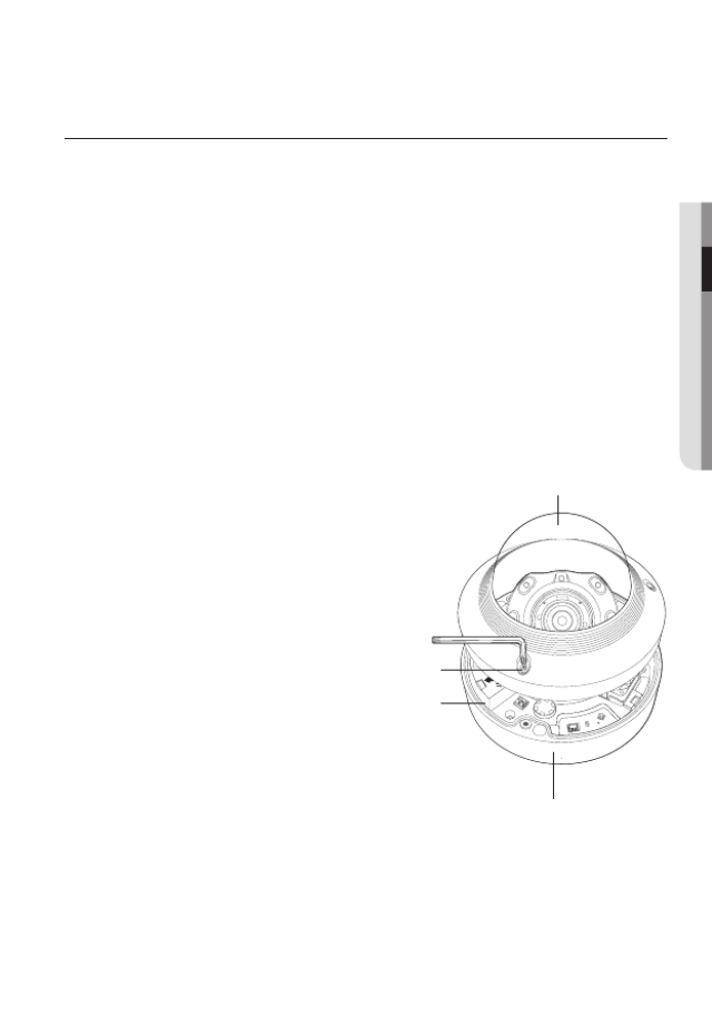
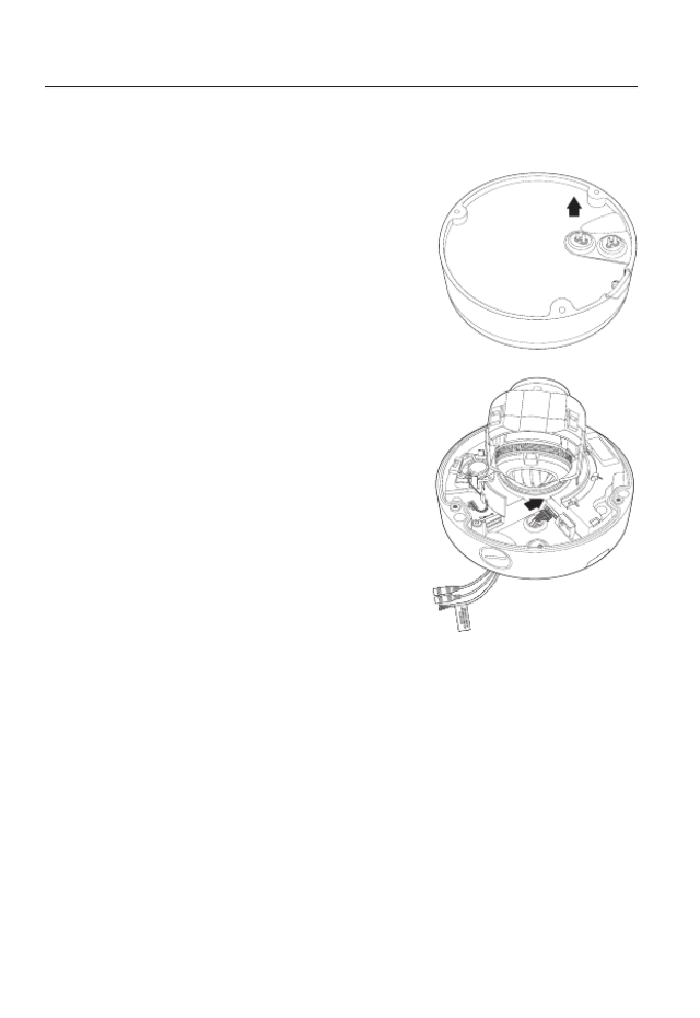
Disassembling
1. With the provided L-wrench and
drill bit, loosen 3 bolts on the dome
cover counter clockwise to remove
the cover.
RESET
VIDE O
F
W
AF
T
N
AC 24V / DC 12V
+ -
Bolts
Dome cover
Camera Case
Camera Body
installation & connection
26_ installation & connection
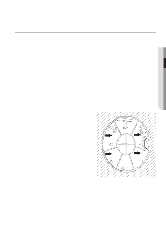
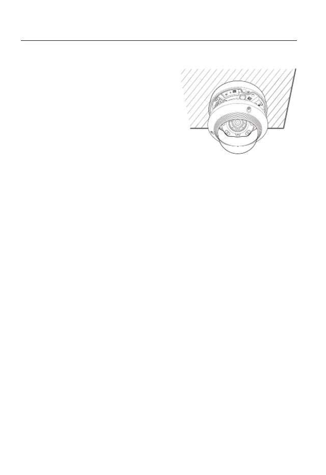
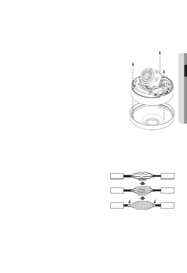
Installation
1. Using the template provided as an
accessory, drill the screw installation
hole(diameter of 6mm, minimal depth of
55mm) and firmly insert the plastic anchor
provided as an accessory to the end.
2. Fit the bottom hole to the anchor hole and
insert and fix the taping screw (M4.5xL50).
3. Connect and arrange the necessary cables
lest that they should be damaged or twisted
while installing the camera.
4. Adjust the lens in a desired direction by referring to the “Adjusting the monitoring
direction for the camera” section. (page 32)
5. Close the dome cover.
`To ensure waterproofing, tight up the fixing bolts using the L-wrench and drill bit.
RESET
VIDEO
F
W
AF
T
N
AC 24V / DC 12V
+ -
English _27
● INSTALLATION & CONNECTION
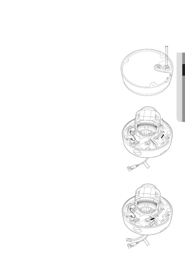
Connecting waterproof power cable and LAN cable
1. Remove the dome cover and the case.
2. Pull out the long projected part of the rubber plug on
the bottom and remove it as shown in the figure.
J
`Use an appropriate cable bush for the LAN cable to be
connected.
- Basic camera : Use the cable with a diameter of Ø5~6.5.
- Components provided : Use the cable with a diameter of
Ø7~8.5.
3. Insert the power cable into the small hole made by
removing the projected part of the rubber plug in step
2 above, and lay the cable along the long groove.
4. Connect the power cable with the power terminal
block.
5. Insert the LAN cable into the large hole made by
removing the projected part of the rubber plug in step
2 above.
6. Remove the sheath with a cable cutter, and align the
cables.
7. Connect the LAN cable with a LAN connector, and
insert it into the LAN tool.
8. Connect the finished cable to the Ethernet port.
CAUTION : Be w are of the
Rated Vo ltage and P olarit y
of the power conne ction.
CAUTION : Be w are of the
Rated Vo ltage and P olarit y
of the power conne ction.
installation & connection
28_ installation & connection
Connecting alarm cable
1. Remove the dome cover and the case.
2. Pull out the rubber plug on the bottom as shown in
the figure.
3. Insert the alarm cable into the hole made by
removing the rubber plug in step 2, and connect the
cable with the PCB alarm terminal.
4. Align the cable so that it should not be damaged or
jammed when installing the camera.
5. Put the rubber plug of the alarm cable into the hole.
6. Adjust the lens in a desired direction by referring to
the “Adjusting the monitoring direction for the
camera” section.
(page
32
)
7. Attach the dome cover.
English _29
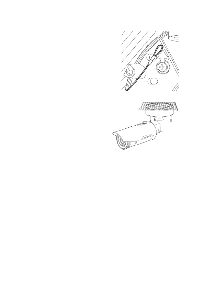
● INSTALLATION & CONNECTION
Attaching to the unbundled adapter
Choose and purchase a necessary one of the following options (unbundled) that is suitable
to the installation site or for your convenience.
1. Remove the dome cover from the case by referring to
the “ ” section. (page 25)Disassembling
2. Use the provided machine screw to fix the camera
case to the unbundled adapter.
3. Connect and arrange the necessary cables lest that
they should be damaged or twisted while installing the
camera.
4. Install the camera body in the reverse order of
“ ”.Disassembling
5. Adjust the lens in a desired direction by referring to the
“ ” Adjusting the monitoring direction for the camera
section. (page 32)
6. Close the dome cover.
`To ensure waterproofing, tight up the fixing bolts using the
L-wrench and drill bit.
Outdoor installation
When you install it outside of the building, please waterproof it with waterproof butyl rubber
tape (can be purchased in stores) so that water does not leak from the gap of the cable
connected to the outside.
1. Connect the power, I/O, AUDIO, and LAN
cables.
2. Wrap the black cable jacket (Area A) and the
cable connection area with waterproof (butyl
rubber) tape so that more than half of the
butyl rubber tape is overlapped.
J
`If the cable jacket is not waterproofed properly,
then it can directly cause leakage. Make sure to
protect the cable with a dense layer of taping.
`Waterproof butyl tape is made of butyl rubber that can be stretched to twice its normal length.
Ca erm a
Ca erm a
Ca erm a
S temys
S temys
S temys
AA
installation & connection
30_ installation & connection
Optional Accessories for Installation
For your easier installation, you can purchase appropriate optional accessories available.
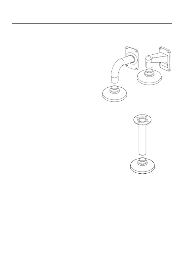
1. WALL MOUNT ADAPTOR(SBP-300WM or
SBP-300WM1)/HANGING MOUNT
(SBP-300HM6)
This adaptor is used when installing the
dome camera onto a wall.
2. CEILING MOUNT ADAPTOR(SBP-300CM)/
HANGING MOUNT(SBP-300HM6)
This adaptor is used when installing the dome
camera on a concrete ceiling.
English _31
● inStaLLation & connection
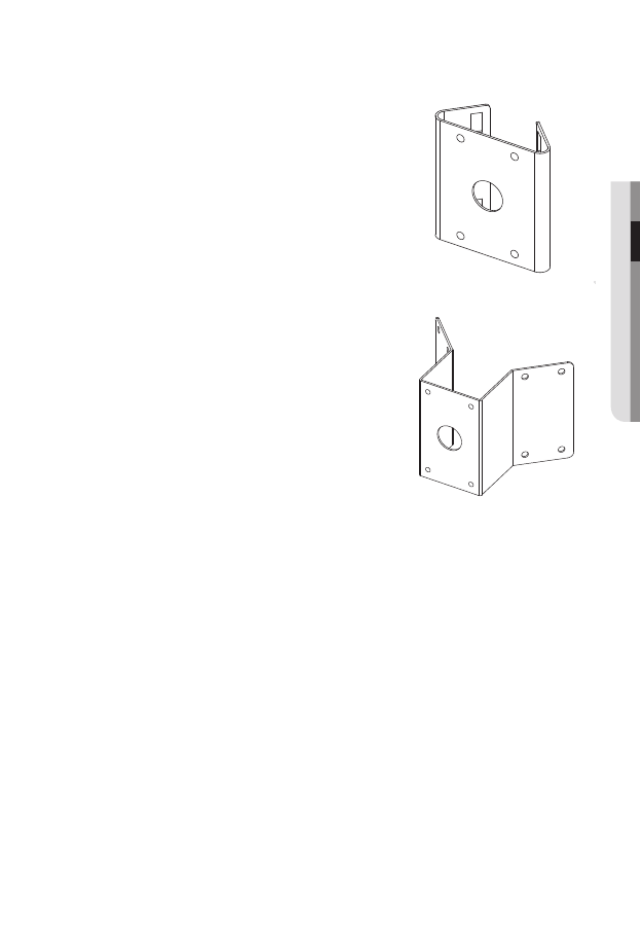
3. POLE MOUNT ADAPTOR(SBP-300PM)
This is an adaptor for WALL MOUNT ADAPTOR
(SBP-300WM or SBP-300WM1) installation on a
pole whose diameter is bigger than 80mm.
4. CORNER MOUNT ADAPTOR (SBP-300KM)
This is an adaptor for WALL MOUNT ADAPTOR
(SBP-300WM or SBP-300WM1) installation on
the corner of wall joint.
installation & connection
32_ installation & connection
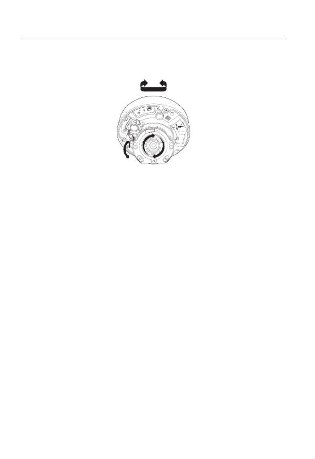
Adjusting the monitoring direction for the camera
`Adjusting the monitoring direction
You can adjust the camera direction only when the camera is fixed on the ceiling.
Where, rotating the camera unit to the left or right is called Pan, adjusting the tilt is called
Tilt, and turning the lens on its axis is called Rotation.
- The effective range of pan is a total of 354 degrees.
- The effective range of rotation is a total of 355 degrees.
- The effective range of tilt is a total of 67 degrees.
J
`The image can be covered up by the camera case depending on the angle.
`Do not forcefully turn the focus/zoom lens after the dome case is disassembled.
Otherwise, it may cause an incorrect focus due to a motor failure.
`Methods of adjustment
1. After installing the camera, adjust the panning angle in consideration of the
monitoring direction.
2. Set the horizontal angle so that the image is not reversed.
3. Adjust the tilt angle so that the camera faces toward the monitoring object.
AC 24V / DC 12V
RESET
VIDEO
F
W
AF
T
N
+ -
Pan
Tilt
Lens rotation
English _33
● INSTALLATION & CONNECTION
INSERTING/REMOVING A MICRO SD MEMORY CARD
J
`Disconnect the power cable from the camera before inserting the Micro SD memory card.
`Do not insert the Micro SD memory card while it’s upside down by force.
Otherwise, it may damage the Micro SD memory card.
`
When it rains or the humidity is high, insertion or ejection of a Micro SD card is not recommended.
`
Disassembly of the product cover should be finished within 5 minutes, or there will be the risk of
internal dew condensation.
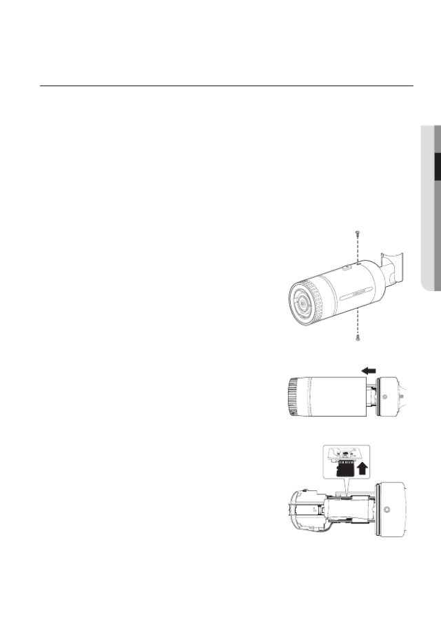
Inserting a Micro SD Memory Card (SNO-8081R)
1. Loosen two screws on the camera.
2. Pull and separate the front cover.
3. Insert a Micro SD card in the arrow direction shown
in the figure.
DESICCANTS
DES ICCANT S
installation & connection
34_ installation & connection
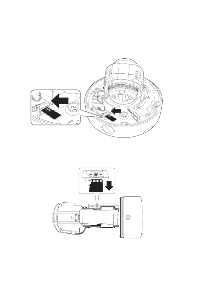
Inserting a Micro SD Memory Card (SNV-8081R)
1. Separate the Dome cover of the camera.
2. Insert a Micro SD card in the arrow direction shown in the figure.
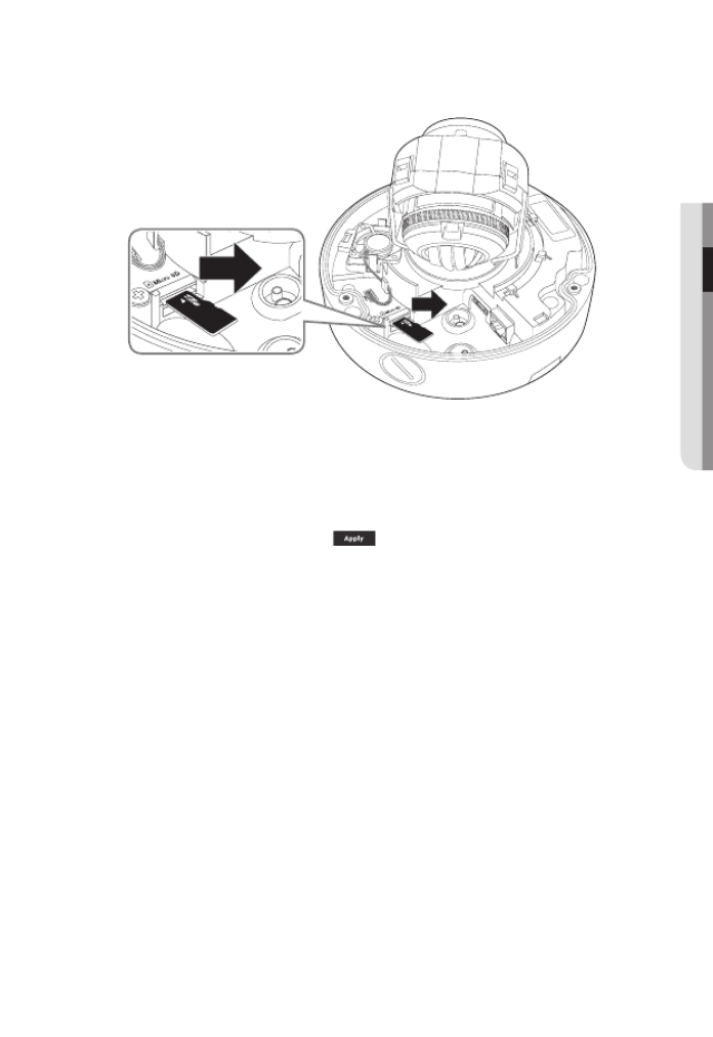
Removing a Micro SD Memory Card
Gently press down on the exposed end of the memory card as shown in the diagram to
eject the memory card from the slot.
DESICCANTS
<SNO-8081R>
English _35
● inStaLLation & connection
<SNV-8081R>
J
`Pressing too hard on the Micro SD memory card can cause the card to shoot out uncontrollably
from the slot when released.
`Before removing your Micro SD memory card, turn off the camera or go to < >, turn the Storage
device off, and press the [Apply ( )] button. (Page 106)
`If you turn off the camera or remove the Micro SD memory card that contains data from the
product, the data may be lost or damaged.
installation & connection
36_ installation & connection
MEMORY CARD INFORMATION (NOT INCLUDED)
What is a memory card?
The memory card is an external data storage device that has been developed to offer an
entirely new way to record and share video, audio, and text data using digital devices.
Selecting a memory card that’s suitable for you
Your camera supports Micro SD/SDHC/SDXC memory cards.
You may, however, experience compatibility issues depending on the model and make of
the memory card.
For your camera, we recommend you use a memory card from the following
manufacturers:
Micro SD/SDHC/SDXC Memory Card : Sandisk, Transcend
Memory cards of 4GB ~ GB is recommended for using with this camera.128
Playback performance can be affected depending on the speed of memory card, so use
the high-speed memory card.
For the framerate below 30 fps, it is recommended to use the specification memory card of
Class 6 or higher.
For the framerate over 31 fps, it is recommended to use the specification memory card of
Class 10 UHS or higher.
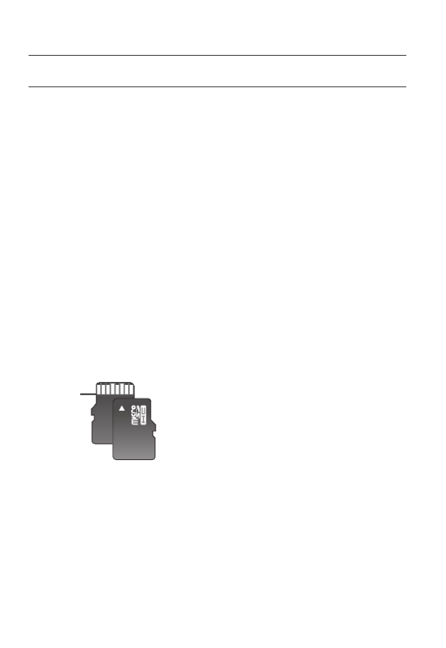
Memory Card Components
Micro SD/SDHC/SDXC
Contacts
English _37
● inStaLLation & connection
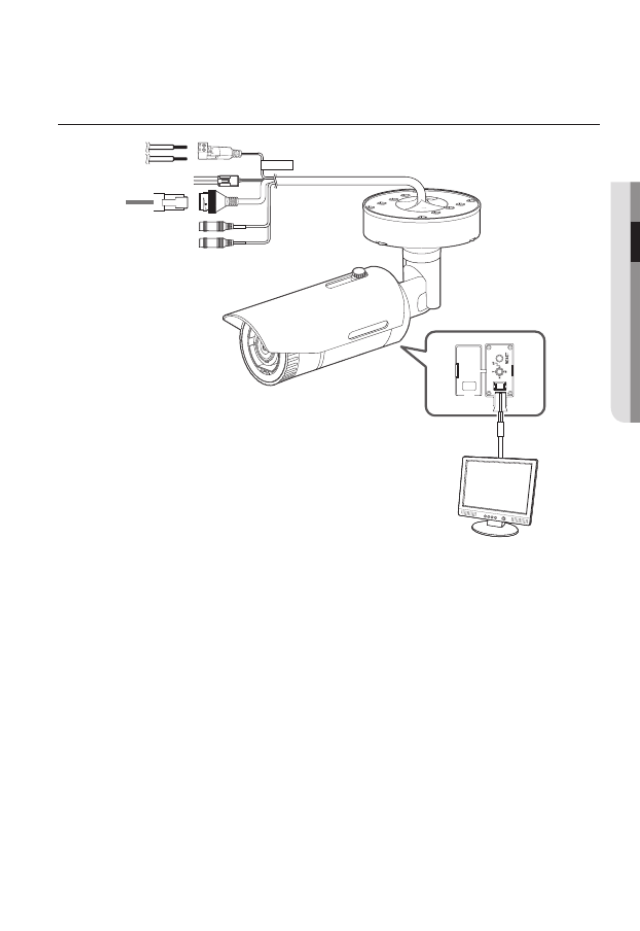
connectinG witH otHer Device
<SNO-8081R>
CAU T IO N :Be ware of the
Rated Voltage and Polarity
of t he powe r connection.
Ethernet
Power
Monitor to install
installation & connection
38_ installation & connection
J
`The CVBS out terminal of the product is provided for easier installation, and is not recommended
for monitoring purposes.
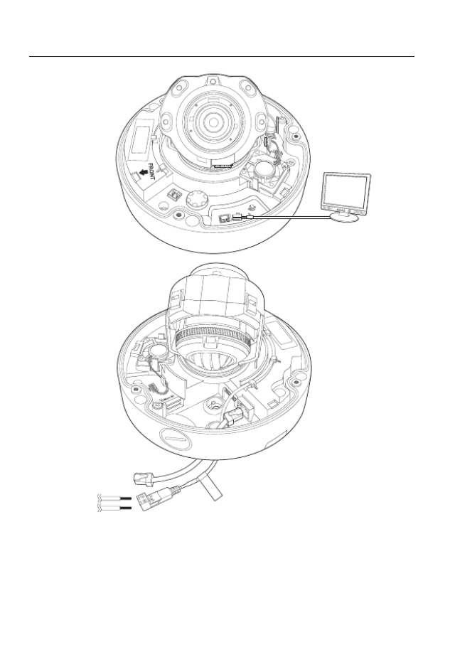
<SNV-8081R>
AC 24V / DC 12V
RESET
VID EO
F
W
AF
T
N
+ -
Monitor to install
CAUTI ON: B e ware of th e
Rated Volta ge and Polar ity
of th e pow er con necti on.
Ethernet
Power
English _39
● INSTALLATION & CONNECTION
Ethernet Connection
Connect the Ethernet cable to the local network or to the Internet.
Power Supply
Use the screwdriver to connect each line (+, –) of the power cable to the corresponding
power port of the camera.
J
`If you turn on PoE and DC12V and AC24V at the same time, the first applied one will be used
the power source.
- You can also use a router featuring PoE to supply power to the camera.
- Use PoE that is compliant with the IEEE 802.3af protocols.
`Be careful not to reverse the polarity when you connect the power cable.
`AC 24V can be connected in non-polar union.
`If you want to connect an external device, you must turn off the external device before proceed
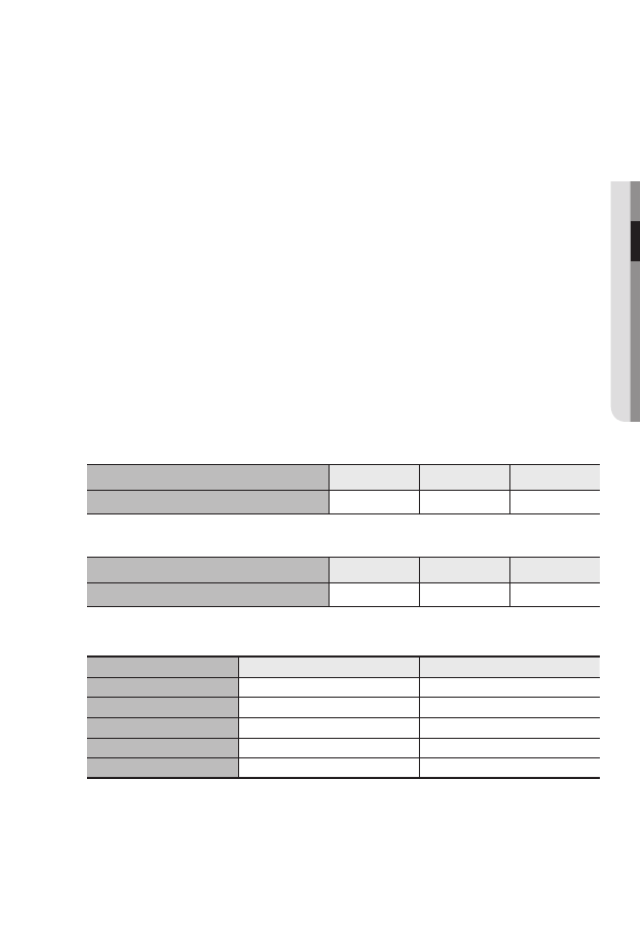
Power Cable Specification for Each Model
In case of DC 12V Input:
Wire Type (AWG) #22 #20 #18
Cable Length (Max.) 24m 38m 60m
In case of AC 24V Input:
Wire Type (AWG) #22 #20 #18
Cable Length (Max.) 34m 55m 88m
Network Cable Specification
Item Contents Remark
Connector RJ45
Ethernet 10/100Base-T 10/100 Mbps
Cable UTP Category 5e
Max Distance 100M
PoE Support IEEE 802.3af
installation & connection
40_ installation & connection
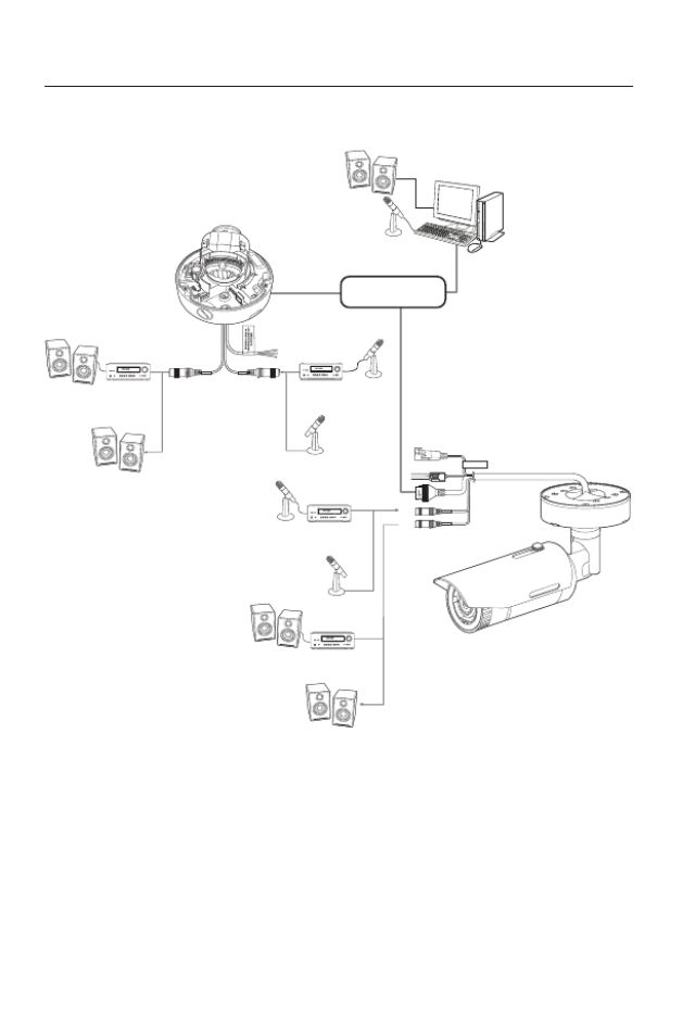
Connecting to Audio Input/Output
CAUTION:Be w are of th e
Rated Voltage and Polarity
of the power connecti on.
Network
PC
Microphone
Speaker
Speaker
Speaker
Speaker
Amp
Amp Amp
Microphone
Microphone
Amp
Microphone
Microphone
Speaker

English _41
● INSTALLATION & CONNECTION
1. Connect the AUDIO IN port of the camera with the microphone or LINE OUT port of
the amplifier that the microphone is connected to.
2. Connect the AUDIO OUT port of the camera with the speaker or LINE IN port of the
amplifier that the speaker is connected to.
3. Check the specifications for audio input.
• Audio Codec
- Audio In : G.711 PCM (Bit Rate: 64kbps / Sampling Frequency: 8kHz), G.726
ADPCM (Bit Rate: 16Kbps, 24Kbps, 32Kbps, 40Kbps / Sampling Frequency: 8kHz)
- Audio Out : G.711 PCM (Bit Rate: 64kbps / Sampling Frequency: 8kHz)
• Full duplex Audio
• Audio in : Mono signal line input (Max.2.4 Vpp)
• Audio out : Mono signal line output (Max.2.4 Vpp)
• Line out impedance : 600Ω
installation & connection
42_ installation & connection
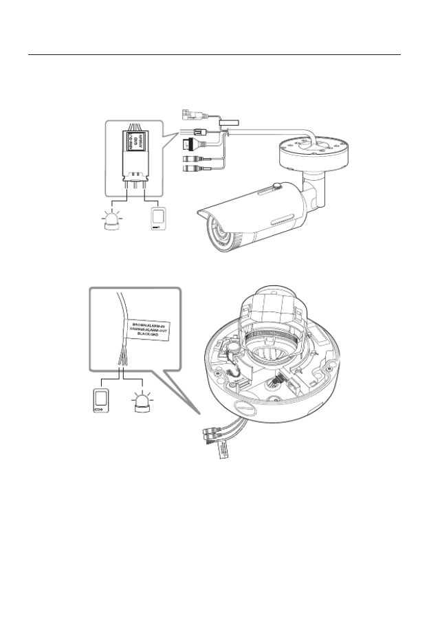
Connecting to the I/O port box
Connect the Alarm I/O cable to the corresponding port of the port box.
• ALARM-IN : Used to connect the alarm input sensor or external day/night sensor.
• ALARM-OUT : Used to connect the alarm output signal.
• GND : These are common ports to connect alarm input/output signals.
J
`If devices (e.g., flashing light and siren) that exceed the voltage and current specifications are
connected by using the open collector method, it may cause malfunction.
Refer to the “ ” when connecting devices that exceed the voltage and Alarm Out Wiring Diagram
current specifications. (page 43)
CAUTION:Be ware of the
Rated Voltage an d Polari ty
of the powe r connec tion.
Alarm
(Warning lamp)
Sensor
<SNO-8081R>
<SNV-8081R>
Sensor Alarm
(Warning lamp)
English _43
● INSTALLATION & CONNECTION
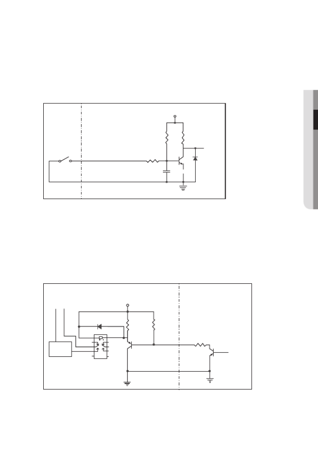
To connect the external sensor
Connect one strand of each signal line (2-strand) of the sensors to the [ ] port, ALARM IN
and connect the other strand to the [ ] port.GND
Alarm In Wiring Diagram
To connect the alarm out
If devices (e.g., flashing light and siren) that exceed the voltage and current specifications
are connected by using the open collector method, it may cause malfunction.
Refer to the alarm out connection diagram below when connecting devices that exceed the
voltage and current specifications.
Alarm Out Wiring Diagram
Sensor
GND
RESISTORALARM IN (5mA SINK)
RESISTOR RESISTOR
VCC_3.3V
DIODE
GND
MLCC TRANSISTOR
External
connection
Inside of the camera
Warning lamp /
Siren power
Warning lamp /
Siren
(
-
) (
+
)
ALARM OUT (12VDC 20mA MAX)
RESISTOR 10K ohm
DIODE
RELAY
DC 5V or 3.3V
TRANSISTOR
GND
GND
TRANSISTOR
External connection Inside of the camera
GND
RESISTOR
44_ network connection and setup
network connection and setup
You can set up the network settings according to your network configurations.
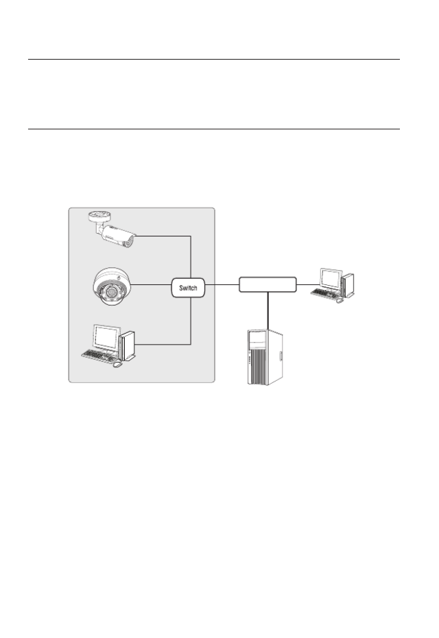
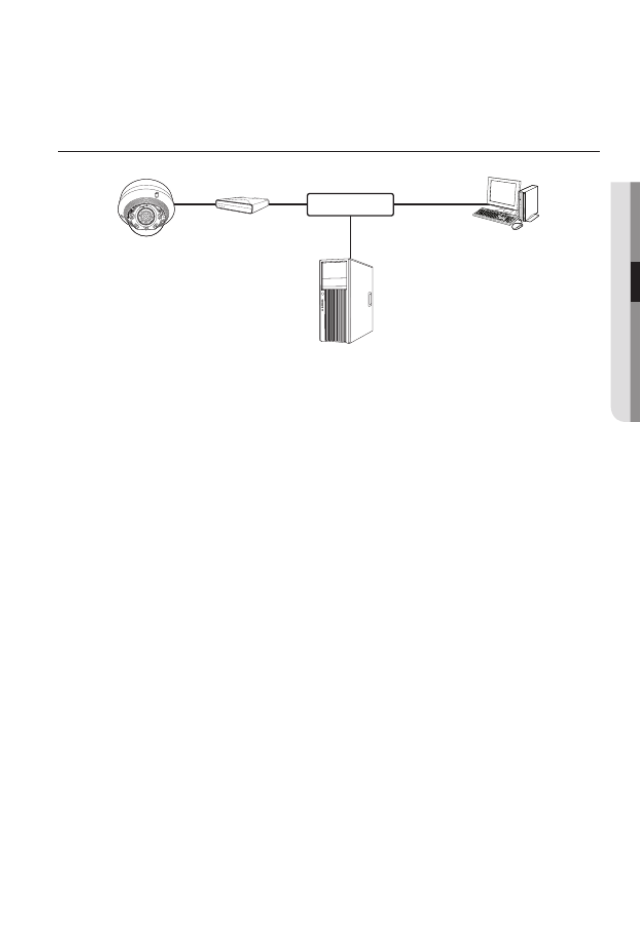
CONNECTING THE CAMERA DIRECTLY TO LOCAL AREA
NETWORKING
Connecting to the camera from a local PC in the LAN
1. Launch an Internet browser on the local PC.
2. Enter the IP address of the camera in the address bar of the browser.
M
`A remote PC in an external Internet out of the LAN network may not be able to connect to the
camera installed in the intranet if the port-forwarding is not properly set or a firewall is set.
In this case, to resolve the problem, contact your network administrator.
`In the IP installer, you can use the initial password, “ ” to set IP Address, Subnet Mask, 4321
Gateway, HTTP Port, VNP Port, IP type. After changing the network interface, for better security,
access the web viewer and change the password.
`By factory default, the IP address will be assigned from the DHCP server automatically.
If there is no DHCP server available, the IP address will be set to 192.168.1.100.
To change the IP address, use the IP Installer.
For further details on IP Installer use, refer to “ ”. (Page Static IP Setup 49)
<Local Network>
Camera
Camera
Local PC
INTERNET
External Remote PC
DDNS Server
(Data Center, KOREA)
English _45
●
NETWORK CONNECTION AND SETUP
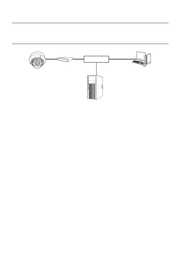
CONNECTING THE CAMERA DIRECTLY TO A DHCP
BASED DSL/CABLE MODEM
1. Connect the user PC directly with the network camera.
2. Run the IP Installer and change the IP address of the camera so that you can use
the web browser on your desktop to connect to the Internet.
3. Use the Internet browser to connect to the web viewer.
4. SetupMove to [ ] page.
5. Network DDNSMove to [ ] – [ ] and configure the DDNS settings.
6. Basic IP & Port DHCPMove to [ ] – [ ], and set the IP type to [ ].
7. Connect the camera, which was removed from your PC, directly to the modem.
8. Restart the camera.
M
`For configuring the DDNS settings, refer to “ ”. (page DDNS 95)
`For registering the DDNS settings, refer to “ ”. (page Registering with DDNS 96)
`Refer to “IP & Port” for how to setup IP. (page 81)
Camera External Remote PC
DDNS Server
(Data Center, KOREA)
DSL/Cable Modem
INTERNET
46_ network connection and setup
network connection and setup
CONNECTING THE CAMERA DIRECTLY TO A PPPoE
MODEM
1. Connect the user PC directly with the network camera.
2. Run the IP Installer and change the IP address of the camera so that you can use
the web browser on your desktop to connect to the Internet.
3. Use the Internet browser to connect to the web viewer.
4. SetupMove to [ ] page.
5. Network DDNSMove to [ ] – [ ] and configure the DDNS settings.
6. Basic IP & Port PPPoEMove to [ ] – [ ] Setup Page, set the IP type to [ ], and enter the
network service’s ID and password.
7. Connect the camera, which was removed from your PC, directly to the modem.
8. Restart the camera.
M
`For configuring the DDNS settings, refer to “ ”. (page DDNS 95)
`For registering the DDNS settings, refer to “ ”. (page Registering with DDNS 96)
`Refer to “IP & Port” for how to setup IP. (page 81)
Camera External Remote PC
DDNS Server
(Data Center, KOREA)
PPPoE Modem
INTERNET
English _47
●
NETWORK CONNECTION AND SETUP
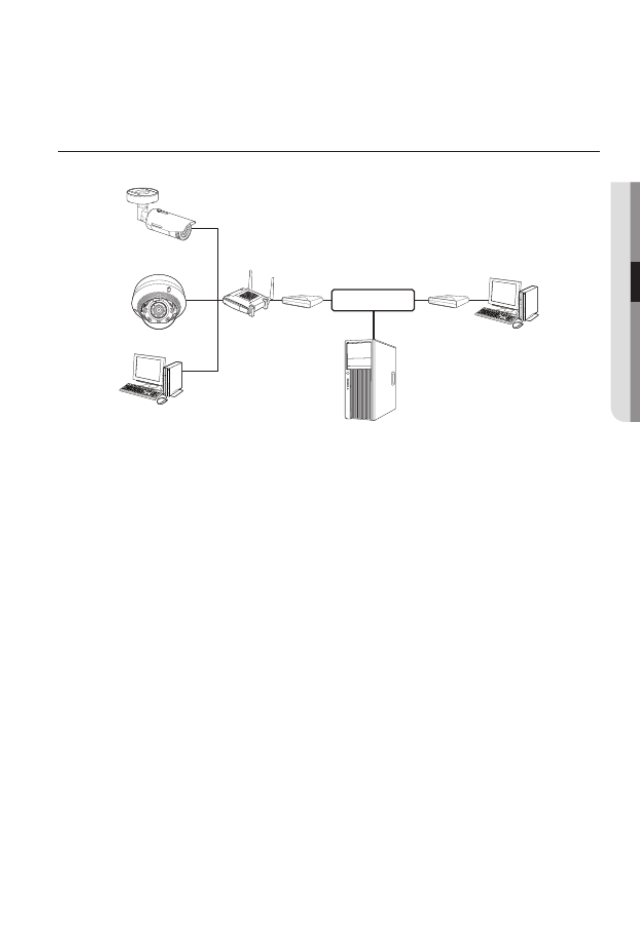
CONNECTING THE CAMERA TO A BROADBAND ROUTER
WITH THE PPPoE/CABLE MODEM
This is for a small network environment such as homes, SOHO and ordinary shops.
Configuring the network settings of the local PC connected to a
Broadband Router
Configuring the network settings of the local PC connected to a Broadband Router, follow
the instructions below.
• Select : < > Network < > Properties < > Local Area Connection < > General
< > Properties < > Internet Protocol (TCP/IP) < > Properties <Obtain an
IP address automatically Use the following IP address> or < >.
• Follow the instructions below if you select < >:Use the following IP address
ex1) If the address (LAN IP) of the Broadband Router is 192.168.1.1
IP address : 192.168.1.100
Subnet Mask : 255.255.255.0
Default Gateway : 192.168.1.1
ex2) If the address (LAN IP) of the Broadband Router is 192.168.0.1
IP address : 192.168.0.100
Subnet Mask : 255.255.255.0
Default Gateway : 192.168.0.1
ex3) If the address (LAN IP) of the Broadband Router is 192.168.xxx.1
IP address : 192.168.xxx.100
Subnet Mask : 255.255.255.0
Default Gateway : 192.168.xxx.1
M
`For the address of the Broadband Router, refer to the product’s documentation.
`For more information about port forwarding of the broadband router, refer to "Port Range
Forward (Port Mapping) Setup”. (Page 54)
Camera
Camera
Local PC
Broadband
Router
PPPoE or
Cable Modem
PPPoE or
Cable Modem
External Remote PC
DDNS Server
(Data Center, KOREA)
INTERNET
48_ network connection and setup
network connection and setup
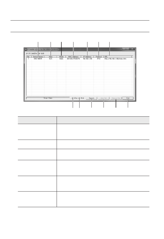
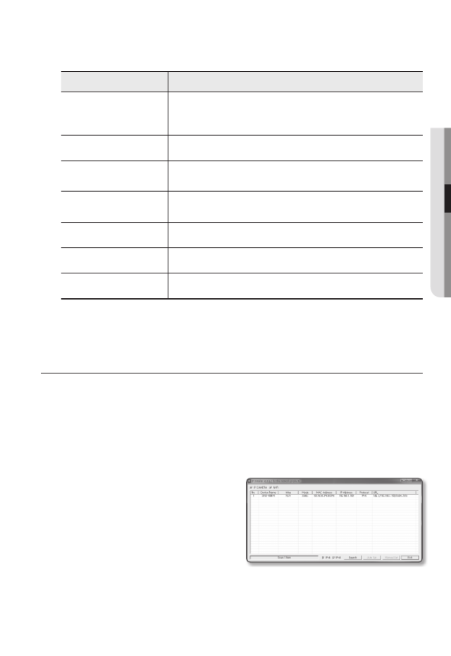
ButtonS uSeD in ip inStaLLer
Item Description
a
Device Name
Model name of the connected camera.
Click the column to sort the list by model name.
However, search will be stopped if clicked during the search.
b
Alias This function is not currently implemented.
c
Mode Displays either < >, < > or < > for the current network Static Dynamic PPPoE
connection status.
d
MAC(Ethernet)
Address
Ethernet address for the connected camera.
Click the column to sort the list by Ethernet address.
However, search will be stopped if clicked during the search.
e
IP Address
IP address.
Click the column to sort the list by IP address.
However, search will be stopped if clicked during the search.
f
Protocol
Network setting for the camera.
The factory default is “IPv4”.
Cameras with the IPv6 setting will be displayed “IPv6”.
a b c d e f g
h i j k l m
English _49
●
NETWORK CONNECTION AND SETUP
Item Description
g
URL
DDNS URL address enabling access from the external Internet.
However, this will be replaced with the < > of the camera if IP Address
DDNS registration has failed.
h
IPv4 Scans for cameras with the IPv4 setting.
i
IPv6 Scans for cameras with the IPv6 setting.
Activated in an IPv6 compliant environment only.
j
Search Scans for cameras that are currently connected to the network.
However, this button will be grayed out if neither IPv4 nor IPv6 is checked.
k
Auto Set The IP Installer automatically configures the network settings.
l
Manual Set You should configure the network settings manually.
m
Exit Exits the IP Installer program.
M
`
For the IP installer, use only the installer version provided in the installation CD or use the latest o
available. You can download the latest version from the Hanwha Techwin web site.
STATIC IP SETUP
Manual Network Setup
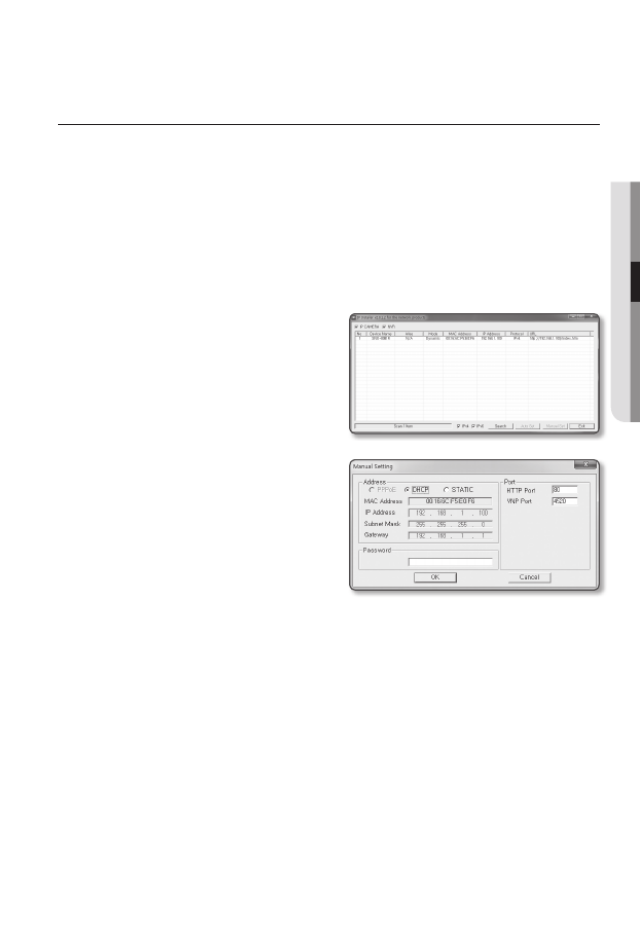
Run < > to display the camera search list.IP Installer_v2.XX.exe
At the initial startup, both [ ] and [ ] will be grayed out.Auto Set Manual Set
M
`For cameras found with the IPv6 setting, these buttons will be grayed out as the cameras do no
support this function.
1. Select a camera in the search list.
Check the MAC address of the camera
on the camera’s label.
Both the [ ] and [ ] Auto Set Manual Set
buttons will be activated.
2. Manual SetClick [ ].
The Manual Setting dialog appears.
< >, < >, IP Address Subnet Mask
< >, < >, and < > of the camera are displayed in the Gateway HTTP Port VNP Port
preset values.
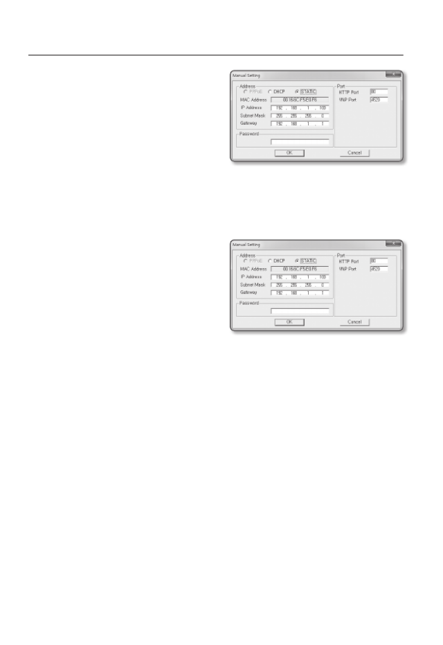
50_ network connection and setup
network connection and setup
3. AddressIn the < > pane, provide the
necessary information.
• MAC (Ethernet) Address : The MAC
address imprinted on the camera
label is automatically displayed and
requires no user setting.
M
`IP related parameters can be set only
when DHCP is not checked.
If not using a Broadband Router
For setting < >, < >, and < >, contact your network IP Address Subnet Mask Gateway
administrator.
4. PortIn the < > pane, provide necessary
information.
• HTTP Port : Used to access the
camera using the Internet browser,
defaulted to 80.
• VNP Port : Used to control the video
signal transfer, defaulted to 4520.
5. Enter the password.
Enter the password of “ ” account, which was used to access the camera.admin
J
`For the security purposes, you are recommended to use a combination of numbers, alphabets
uppercase and lowercase and special characters for your password.
`If you want to change the password, refer to “ ” of the user Administrator password change
setup. (page 78)
6. OKClick [ ].
Manual network setup will be completed.
English _51
●
NETWORK CONNECTION AND SETUP
If using a Broadband Router
• IP Address : Enter an address falling in
the IP range provided by the Broadband
Router.
ex) 192.168.1.2~254,
192.168.0.2~254,
192.168.XXX.2~254
• Subnet Mask : The < > Subnet Mask
of the Broadband Router will be the
< > of the camera.Subnet Mask
• Gateway : The < > of Local IP Address
the Broadband Router will be the < > of the camera.Gateway
M
`The settings may differ depending on the connected Broadband Router model.
For more information, refer to the user manual of the applicable router.
`For more information about port forwarding of the broadband router, refer to “Port Range
Forward (Port Mapping) Setup”. (Page 54)
If the Broadband Router has more than one camera connected
Configure the IP related settings and the Port related settings distinctly with each other.
ex)
Category Camera #1 Camera #2
IP related settings
IP Address
Subnet Mask
Gateway
192.168.1.100
255.255.255.0
192.168.1.1
192.168.1.101
255.255.255.0
192.168.1.1
Port related settings HTTP Port
VNP Port
8080
4520
8081
4521
M
`If the < > is set other than 80, you must provide the < > number in the address baHTTP Port Port
of the Internet browser before you can access the camera.
ex) http://IP address : HTTP Port
http://192.168.1.100:8080
52_ network connection and setup
network connection and setup
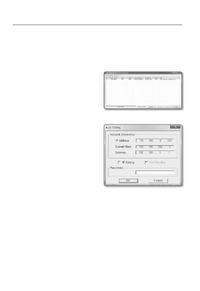
Auto Network Setup
Run < > to display the camera search list.IP Installer_v2.XX.exe
At the initial startup, both [ ] and [ ] will be grayed out.Auto Set Manual Set
M
`For cameras found with the IPv6 setting, these buttons will be grayed out as the cameras do not
support this function.
1. Select a camera in the search list.
Check the MAC address of the camera
on the camera’s label.
Both the [ ] and [ ] Auto Set Manual Set
buttons will be activated.
2. Auto SetClick [ ].
The Auto Setting dialog appears.
The < >, < >, IP Address Subnet Mask
and < > will be set automatically.Gateway
3. Enter the password.
Enter the password of “ ” account, admin
which was used to access the camera.
J
`For the security purposes, you are
recommended to use a combination
of numbers, alphabets uppercase and
lowercase and special characters for your
password.
`If you want to change the password, refer
to “Administrator password change” of
the user setup. (page 78)
4. OKClick [ ].
Auto network setup will be completed.
English _53
●
NETWORK CONNECTION AND SETUP
DYNAMIC IP SETUP
Dynamic IP Environment Setup
• Example of the Dynamic IP environment
- If a Broadband Router, with cameras connected, is assigned an IP address by the
DHCP server
- If connecting the camera directly to modem using the DHCP protocols
- If IPs are assigned by the internal DHCP server via the LAN
Checking the Dynamic IP
1. Run the IP Installer on the user’s local
computer.
Cameras allocated with < > Dynamic IP
address are shown in the list.
2. Select a camera from the search result.
3. Manual SetClick the [ ] button and
check the camera’s < > Dynamic IP
address.
If you uncheck < >, you can DHCP
change IP to < >.Static
54_ network connection and setup
network connection and setup
PORT RANGE FORWARD (PORT MAPPING) SETUP
If you have installed a Broadband Router with a camera connected, you must set the port range
forwarding on the Broadband Router so that a remote PC can access the camera in it.
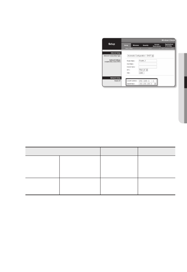
Manual Port Range Forwarding
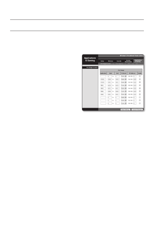
1. From the Setup menu of the Broadband
Router, select <Applications &
Gaming Port Range Forward> - < >.
For setting the port range forward for
a third-party Broadband Router, refer
to the user guide of that Broadband
Router.
2. TCP UDP PortSelect < > and < >
for each connected camera to the
Broadband Router.
Each port number for the Broadband
Router should match that specified in
< > - < > - < > from Setup Basic IP & Port
the camera’s web viewer menu.
3. Save SettingsWhen done, click [ ].
Your settings will be saved.
M
`Above sample instructions are based on the CISCO’s Broadband Router.
`The settings may differ depending on the connected Broadband Router model.
For more information, refer to the user manual of the applicable router.
English _55
●
NETWORK CONNECTION AND SETUP
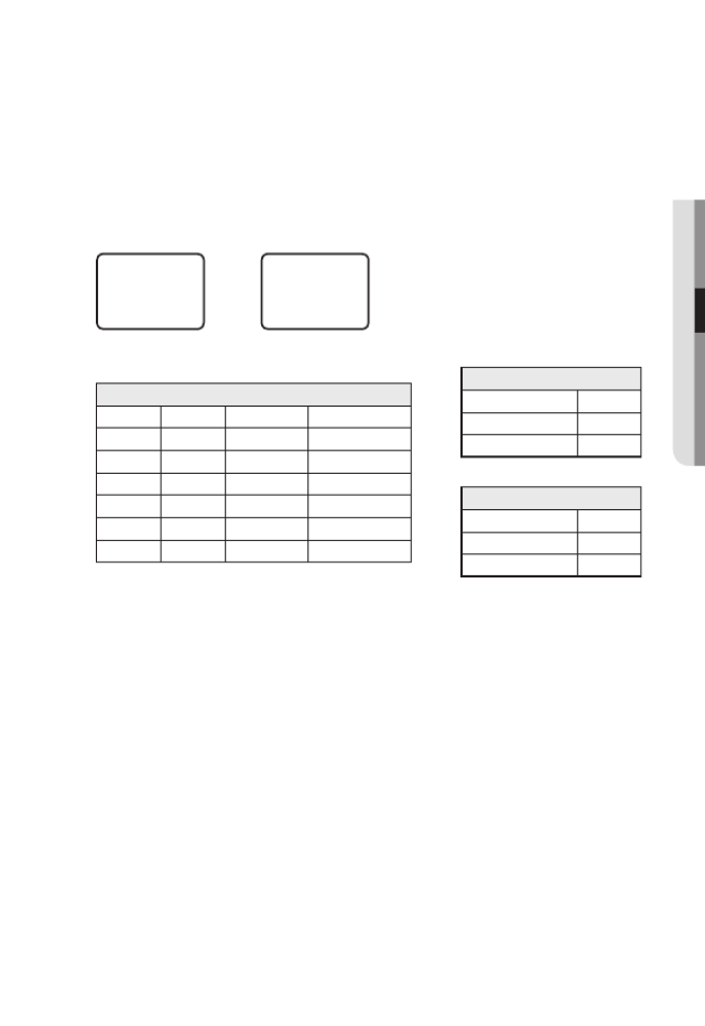
Setting up Port Range Forward for several network cameras
• You can set a rule of Port Forwarding on the Broadband Router device through its
configuration web page.
• A user can change each port using the camera setting screen.
When Camera1 and Camera2 are connected to a router :
M
`Port forwarding can be done without additional router setup if the router supports the UPnP
(Universal Plug and Play) function.
After connecting the network camera, set < > of < > to < > in Quick connect Samsung DDNS On
the “Setup
Network DDNS” menu.
User Internet
Broadband Router
Start End Protocol IP Address
3000 3000 TCP/UDP 192.168.1.100
3001 3001 TCP/UDP 192.168.1.101
4520 4520 TCP/UDP 192.168.1.100
4521 4521 TCP/UDP 192.168.1.101
8080 8080 TCP/UDP 192.168.1.100
8081 8081 TCP/UDP 192.168.1.101
Camera1 (192.168.1.100)
HTTP port 8080
Device port 4520
RTSP port 3000
Camera2 (192.168.1.101)
HTTP port 8081
Device port 4521
RTSP port 3001

56_ network connection and setup
network connection and setup
connectinG to tHe camera from a SHareD LocaL pc
1. Run the IP Installer.
It will scan for connected cameras and
display them as a list.
2. Double-click a camera to access.
The Internet browser starts and
connects to the camera.
M
`Access to the camera can also be gained by typing the camera's IP address in the address bar of
the Internet browser.
connectinG to tHe camera from a remote pc via
tHe internet
Since using the IP Installer on a remote computer that is not in the Broadband Router’s network
cluster is not allowed, users can access cameras within a Broadband Router’s network by using
the camera’s DDNS URL.
1. Before you can access a camera in the Broadband Router network, you should have
set the port range forward for the Broadband Router.
2. From the remote PC, launch the Internet browser and type the DDNS URL address
of the camera, or the IP address of the Broadband Router in the address bar.
ex) http://www.samsungipolis.com/Product ID
M
`For registering the DDNS settings, refer to “ ”. (page Registering with DDNS 96)
English _57
● WEB VIEWER
web viewer
CONNECTING TO THE CAMERA
Normally, you would
1. Launch the Internet browser.
2. Type the IP address of the camera in
the address bar.
ex) • IP address (IPv4) : 192.168.1.100
http://192.168.1.100
- the Login dialog should appear.
• IP address (IPv6) : 2001:230:abcd:
ffff:0000:0000:ffff:1111
http://[2001:230:abcd:ffff:0000
:0000:ffff:1111] - the Login dialog
should appear.
If the HTTP port is other than 80
1. Launch the Internet browser.
2. Type the IP address and HTTP port number of the camera in the address bar.
ex) IP address : 192.168.1.100:HTTP Port number(8080)
http://192.168.1.100:8080 - the Login dialog should appear.
Using URL
1. Launch the Internet browser.
2. Type the DDNS URL of the camera in the address bar.
ex) URL address : http://www.samsungipolis.com/Product ID
- the Login dialog should appear.
J
`Network connection is disabled in the LAN only environment.

58_ web viewer
web viewer
Connecting via UPnP
1. Run the client or operating system in support of the UPnP protocol.
2. Click the camera name for search.
In the Windows operating system, click the camera name searched from the
network menu.
- The login window is displayed.
Connecting via Bonjour
1. Run the client or operating system in support of the Bonjour protocol.
2. Click the camera name for search.
In the Mac operating system, click the camera name searched from the Bonjour tab
of Safari.
- The login window is displayed.
To check the DDNS address
If the camera is connected directly to the DHCP cable modem, DSL modem, or PPPoE
modem, the IP address of your network will be changed each time you try to connect to
the ISP (Internet Service Provider) server.
If this is the case, you will not be informed of the IP address changed by DDNS.
Once you register a dynamic IP-based device with the DDNS server, you can easily check
the changed IP when you try to access the device.
To register your device to the < > server, visit www.samsungipolis.com and register DDNS
your device first, and then set the Web Viewer’s < > - < > to <Network DDNS Samsung
DDNS>, as well as providing < > that had been used for DDNS registration.Product ID
English _59
● WEB VIEWER
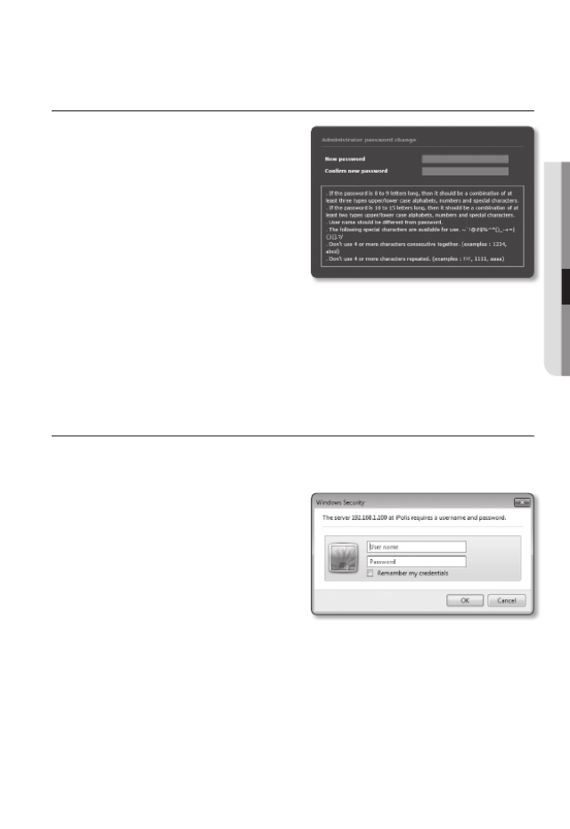
PASSWORD SETTING
When you access the product for the first time,
you must register the login password.
When the “ ” window appears, Password change
enter the new password.
J
`For a new password with 8 to 9 digits,
you must use at least 3 of the following:
uppercase/lowercase letters, numbers
and special characters. For a password
with 10 to 15 digits, you must use at least
2 types of those mentioned.
- Special characters that are allowed. : ~`!@#$%^*()_-+=|{}[].?/
`For higher security, you are not recommended to repeat the same characters or consecutive
keyboard inputs for your passwords.
`If you lost your password, you can press the [ ] button to initialize the product. So, don’RESET
your password by using a memo pad or memorizing it.
LOGIN
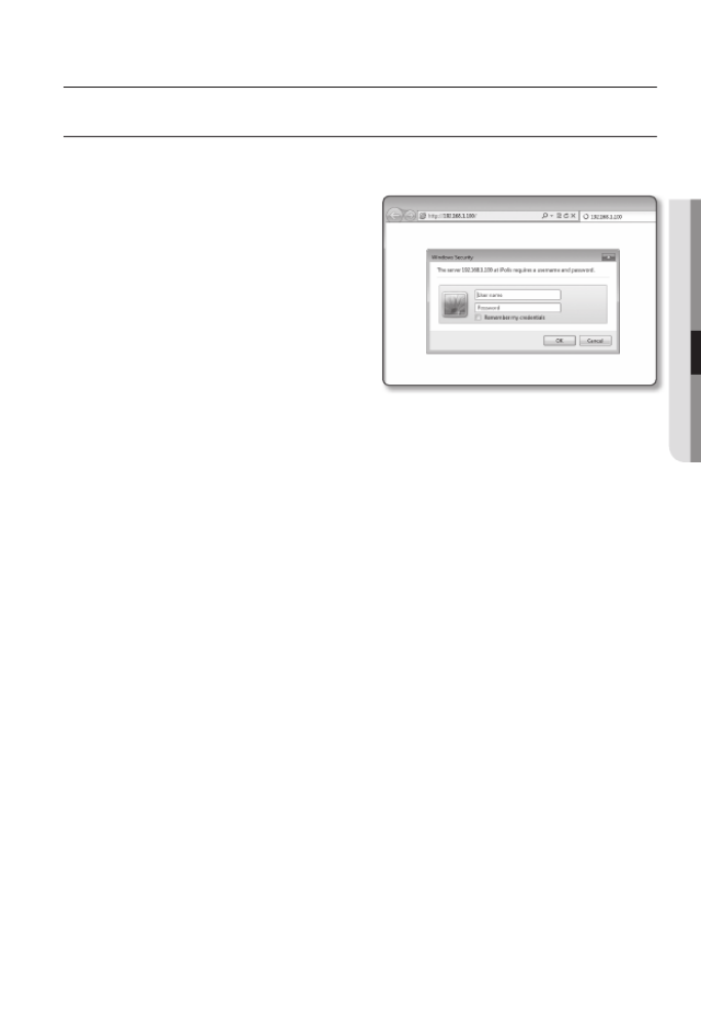
Whenever you access the camera, the login window appears.
Enter the User ID and password to access the camera.
1. admin User nameEnter “ ” in the < >
input box.
The administrator ID, “ ”, is fixed admin
and can not be changed.
2. Enter the password in the <Password>
input field.
3. OKClick [ ].
If you have logged in successfully, you
will the Live Viewer screen.
J
`When you access the camera web viewer, pay special attention to the security by checking
whether the image data is encrypted.
M
`If you check the “ ” option when your input is done, in future you wiRemember my credentials
be logged in automatically without being prompted to enter the login information.
`You will experience the best video quality if the screen size is 100%. Reducing the ratio may c
the image on the borders.
60_ web viewer
web viewer
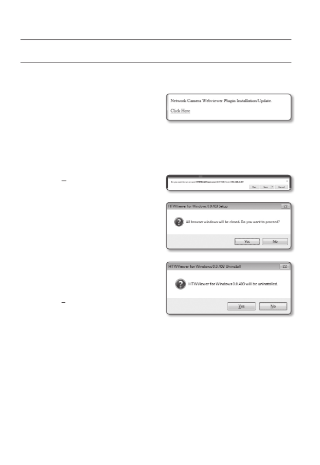
INSTALLING WebViewer PLUGIN
If connecting to a camera for the first time, you will see the installation message. Then, install the
required WebViewer Plugin to access the camera and control the video from it in real time.
1. When the monitoring page is accessed
for the very first time, the installation
page is displayed. Click [ ] to Click Here
begin installation.
J
`If the plug-in installation file download status is suspended at 99% in the Internet Explorer
browser, retry it after selecting “Release SmartScreen filter” in “Tool
SmartScreen filter”.
2. RunClick [ ] in the message window.
3. YesClick [ ] when the notice window
saying that all browser windows will be
closed.
M
`Steps 4 and 5 will be skipped if no Web
Viewer Plug-in is installed.
4. When the old version of the Web Viewer
Plug-in is installed, a notice window
saying the old version will be deleted is
displayed.
Click [Yes] when the notice window is
displayed.
English _61
● WEB VIEWER
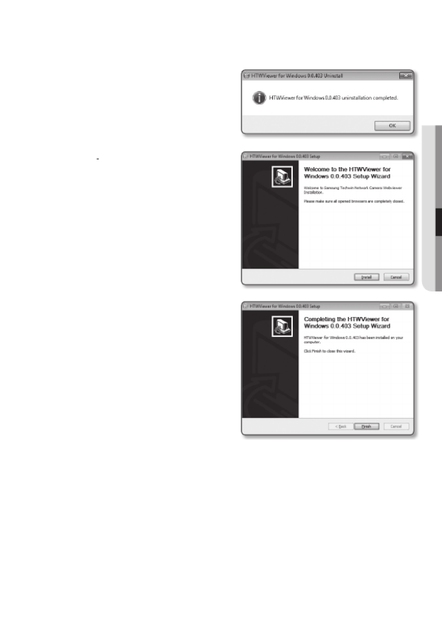
5. OKClick [ ].
The old version of Web Viewer Plug-in
is deleted.
6. InstallClick [ ] to begin installation of the
Web Viewer Plug-in.
7. FinishClick [ ].
Web Viewer Plug-in installation is
completed.
J
`In your internet explorer, if you need to
move to the installation screen after
installing the webviewer plugin, check
whether webviewer_activexplugin_lib.
control in the “Tool
Additional Function
Management” menu is “Activated”. If
not, and if there is a persisting problem,
then select “Tools
Internet Options
General” and delete all the search records.
62_ web viewer
web viewer
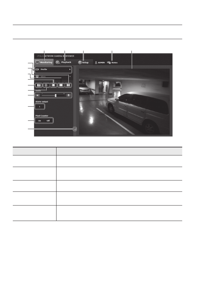
uSinG tHe Live Screen
Item Description
a
Monitoring Move to the monitoring screen.
b
Playback Move to the screen where you can search for the video recording saved in your Micro
SD memory card or NAS.
c
Setup Move to the Setup screen.
d
Profile access
information You can read the profile information.
e
Viewer Screen Displays the Live video on the screen.
`You can use the mouse wheel to activate the digital zooming in Viewer screen.
i
a b c d e
f
g
h
j
k
l
m
n
o

English _63
● weB viewer
Item Description
f
Profile type
You can select a profile type in < > under the < > setup menu.Video profile Basic
`When the Web Viewer is connected, the profile information currently using is
displayed.
J
`
Afterimages can be displayed on the screen under the following conditions if
the video is played in the monitoring page:
- The resolution is changed due to a profile change.
- Incoming data is being slowed due to a network delay when the profile i
changed.
- The web browser window size and location is changed.
`
You cannot watch a profile using H.265 Codec on the web viewer live
monitoring screen.
g
Screen
Optimization The video size of the camera will switch to as big as the Web browser.
h
Fix the resolution Regardless of the resolution setup configured in the camera, it sets the resolution to
640x480. Press it again to switch back to the default resolution.
i
Full Screen Switch the current video to the maximum size of the monitor.
j
Capture Saves the snapshot as an image file in the .jpg format.
k
Instant Recording Users can store videos to a PC by themselves.
`The H.265 Codec video does not support instant recording.
l
Audio/Microphone
Control
Enable Audio and Microphone are control the Audio volume.
`Only the Audio volume can be controlled.
m
Alarm output Activate the Alarm Out port.
n
Pixel Counter It is possible to check the image pixels in a chosen area.
o
Hide the context
menu The left-corner context menu will disappear but only the menu icon.
Produktspecifikationer
| Varumärke: | Hanwha |
| Kategori: | övervakningskamera |
| Modell: | SNV-8081R |
Behöver du hjälp?
Om du behöver hjälp med Hanwha SNV-8081R ställ en fråga nedan och andra användare kommer att svara dig
övervakningskamera Hanwha Manualer

18 Juli 2025

18 Juli 2025

18 Juli 2025

18 Juli 2025

18 Juli 2025

26 Oktober 2024

21 September 2024

20 September 2024

19 September 2024

19 September 2024
övervakningskamera Manualer
- EVE
- BirdDog
- Airlive
- Konig
- Mitsubishi
- CRUX
- AViPAS
- EKO
- LevelOne
- Pelco
- Belkin
- Mobi
- Pioneer
- Kramer
- Wasserstein
Nyaste övervakningskamera Manualer

31 Juli 2025

31 Juli 2025

31 Juli 2025

30 Juli 2025

30 Juli 2025

29 Juli 2025

29 Juli 2025

28 Juli 2025

27 Juli 2025

27 Juli 2025