Hikvision DS-2CD2942F Bruksanvisning
Hikvision
övervakningskamera
DS-2CD2942F
Läs nedan 📖 manual på svenska för Hikvision DS-2CD2942F (165 sidor) i kategorin övervakningskamera. Denna guide var användbar för 3 personer och betygsatt med 4.5 stjärnor i genomsnitt av 2 användare
Sida 1/165

User Manual of Network Camera
1
User Manual
UD.6L0201D1919A01
Network Camera

User Manual of Network Camera
2
User Manual
COPYRIGHT ©2015 Hangzhou Hikvision Digital Technology Co., Ltd.
ALL RIGHTS RESERVED.
Any and all information, including, among others, wordings, pictures, graphs are the
properties of Hangzhou Hikvision Digital Technology Co., Ltd. or its subsidiaries
(hereinafter referred to be “Hikvision”). This user manual (hereinafter referred to be
“the Manual”) cannot be reproduced, changed, translated, or distributed, partially or
wholly, by any means, without the prior written permission of Hikvision. Unless
otherwise stipulated, Hikvision does not make any warranties, guarantees or
representations, express or implied, regarding to the Manual.
About this Manual
This Manual is applicable to Network Camera (V5.3.0).
The Manual includes instructions for using and managing the product. Pictures, charts,
images and all other information hereinafter are for description and explanation only.
The information contained in the Manual is subject to change, without notice, due to
firmware updates or other reasons. Please find the latest version in the company
website ( ). http://overseas.hikvision.com/en/
Please use this user manual under the guidance of professionals.
Trademarks Acknowledgement
and other Hikvision’s trademarks and logos are the properties of
Hikvision in various jurisdictions. Other trademarks and logos mentioned below are
the properties of their respective owners.
Legal Disclaimer
TO THE MAXIMUM EXTENT PERMITTED BY APPLICABLE LAW, THE
PRODUCT DESCRIBED, WITH ITS HARDWARE, SOFTWARE AND
FIRMWARE, IS PROVIDED “AS IS”, WITH ALL FAULTS AND ERRORS, AND
HIKVISION MAKES NO WARRANTIES, EXPRESS OR IMPLIED, INCLUDING
WITHOUT LIMITATION, MERCHANTABILITY, SATISFACTORY QUALITY,

User Manual of Network Camera
3
FITNESS FOR A PARTICULAR PURPOSE, AND NON-INFRINGEMENT OF
THIRD PARTY. IN NO EVENT WILL HIKVISION, ITS DIRECTORS, OFFICERS,
EMPLOYEES, OR AGENTS BE LIABLE TO YOU FOR ANY SPECIAL,
CONSEQUENTIAL, INCIDENTAL, OR INDIRECT DAMAGES, INCLUDING,
AMONG OTHERS, DAMAGES FOR LOSS OF BUSINESS PROFITS, BUSINESS
INTERRUPTION, OR LOSS OF DATA OR DOCUMENTATION, IN
CONNECTION WITH THE USE OF THIS PRODUCT, EVEN IF HIKVISION HAS
BEEN ADVISED OF THE POSSIBILITY OF SUCH DAMAGES.
REGARDING TO THE PRODUCT WITH INTERNET ACCESS, THE USE OF
PRODUCT SHALL BE WHOLLY AT YOUR OWN RISKS. HIKVISION SHALL
NOT TAKE ANY RESPONSIBILITES FOR ABNORMAL OPERATION,
PRIVACY LEAKAGE OR OTHER DAMAGES RESULTING FROM CYBER
ATTACK, HACKER ATTACK, VIRUS INSPECTION, OR OTHER INTERNET
SECURITY RISKS; HOWEVER, HIKVISION WILL PROVIDE TIMELY
TECHNICAL SUPPORT IF REQUIRED.
SURVEILLANCE LAWS VARY BY JURISDICTION. PLEASE CHECK ALL
RELEVANT LAWS IN YOUR JURISDICTION BEFORE USING THIS PRODUCT
IN ORDER TO ENSURE THAT YOUR USE CONFORMS THE APPLICABLE
LAW. HIKVISION SHALL NOT BE LIABLE IN THE EVENT THAT THIS
PRODUCT IS USED WITH ILLEGITIMATE PURPOSES.
IN THE EVENT OF ANY CONFLICTS BETWEEN THIS MANUAL AND THE
APPLICABLE LAW, THE LATER PREVAILS.
Regulatory Information
FCC Information
FCC compliance: This equipment has been tested and found to comply with the
limits for a digital device, pursuant to part 15 of the FCC Rules. These limits are
designed to provide reasonable protection against harmful interference when the
equipment is operated in a commercial environment. This equipment generates, uses,
and can radiate radio frequency energy and, if not installed and used in accordance

User Manual of Network Camera
10
Chapter 1 System Requirement
Operating System: Microsoft Windows XP SP1 and above version / Vista / Win7 /
Server 2003 / Server 2008 32bits
CPU: Intel Pentium IV 3.0 GHz or higher
RAM: 1G or higher
Display: 1024×768 resolution or higher
Web Browser: Internet Explorer 6.0 and above version, Apple Safari 5.02 and above
version, Mozilla Firefox 3.5 and above version and Google Chrome8 and above
version.

User Manual of Network Camera
11
Chapter 2 Network Connection
Note:
You shall acknowledge that the use of the product with Internet access might be
under network security risks. For avoidance of any network attacks and
information leakage, please strengthen your own protection. If the product does
not work properly, please contact with your dealer or the nearest service center.
To ensure the network security of the network camera, we recommend you to
have the network camera assessed and maintained termly. You can contact us if
you need such service.
Before you start:
If you want to set the network camera via LAN (Local Area Network), please a
refer to Section 2.1 Setting the Network Camera over the LAN.
If you want to set the network camera via WAN (Wide Area Network), please a
refer to Section 2.2 Setting the Network Camera over the WAN.
2.1 Setting the Network Camera over the LAN
Purpose:
To view and configure the camera via LAN, you need to connect the network a
camera in the same subnet with your computer, and install the SADP or iVMS-4200
software to search and change the IP of the network camera.
Note: For the detailed introduction of SADP, please refer to Appendix 1.
2.1.1 Wiring over the LAN
The following figures show the two ways of cable connection of network camera a
and computer: a
Purpose:
To test the network camera, you can directly connect the network camera to the
computer with a network cable as shown in Figure 2-1.

User Manual of Network Camera
14
Figure 2-4 SADP Interface
3. Create a password and input the password in the password field, and confirm the
password.
STRONG PASSWORD RECOMMENDED– We highly recommend
you create a strong password of your own choosing (using a minimum
of 8 characters, including upper case letters, lower case letters, numbers,
and special characters) in order to increase the security of your product.
And we recommend you reset your password regularly, especially in the
high security system, resetting the password monthly or weekly can
better protect your product.
4. Click to save the password. OK
You can check whether the activation is completed on the popup window. If activation
failed, please make sure that the password meets the requirement and try again.
5. Change the device IP address to the same subnet with your computer by either
modifying the IP address manually or checking the checkbox of Enable DHCP.

User Manual of Network Camera
15
Figure 2-5 Modify the IP Address
6. Input the password and click the button to activate your IP address Save
modification.
Activation via Client Software
The client software is versatile video management software for multiple kinds of
devices.
Get the client software from the supplied disk or the official website, and install the
software according to the prompts. Follow the steps to activate the camera.
Steps:
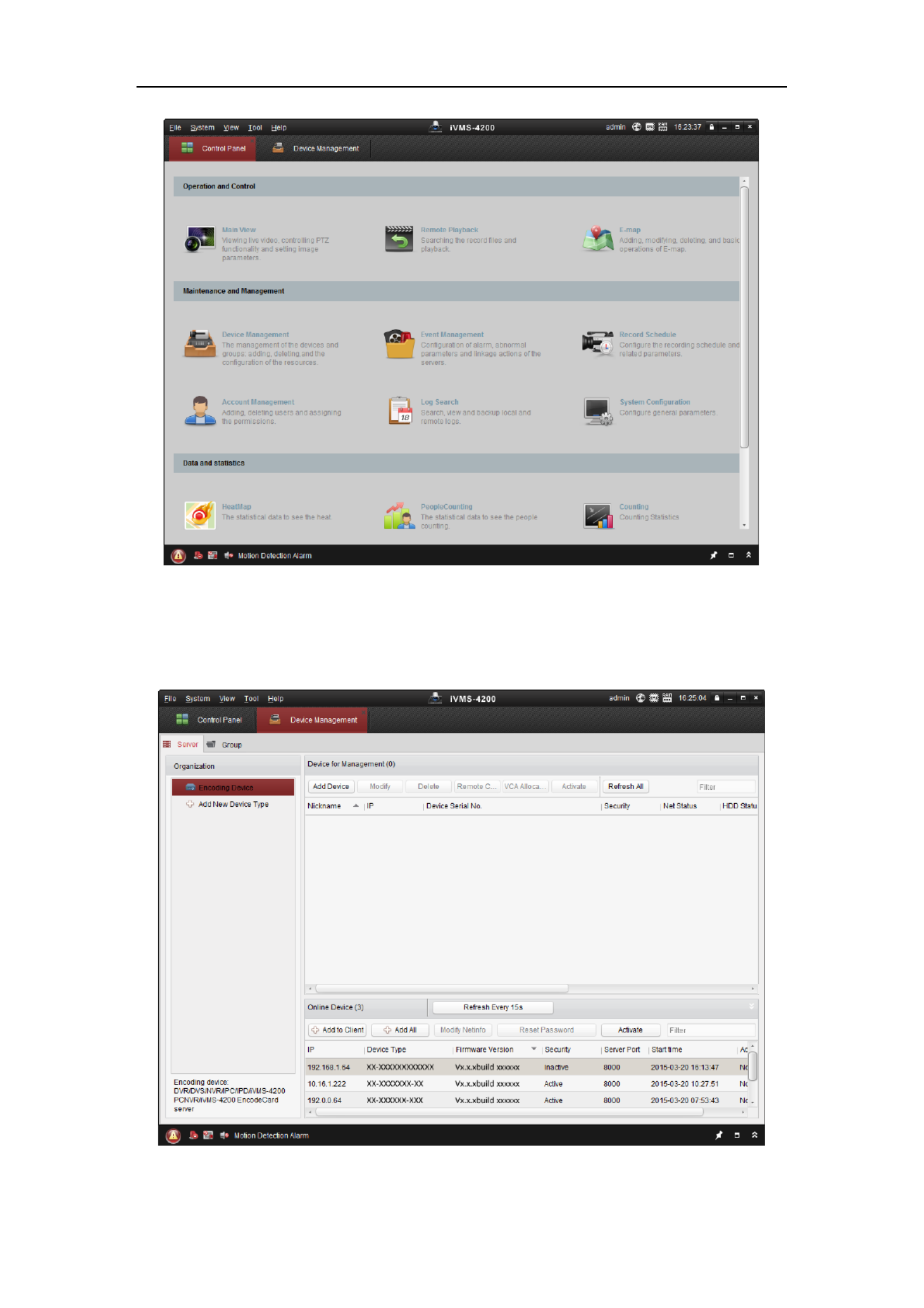
1. Run the client software and the control panel of the software pops up, as shown in
the figure below.
User Manual of Network Camera
16
Figure 2-6 Control Panel
2. Click the icon to enter the Device Management interface, as Device Management
shown in the figure below.
Figure 2-7 Device Management Interface
User Manual of Network Camera
18
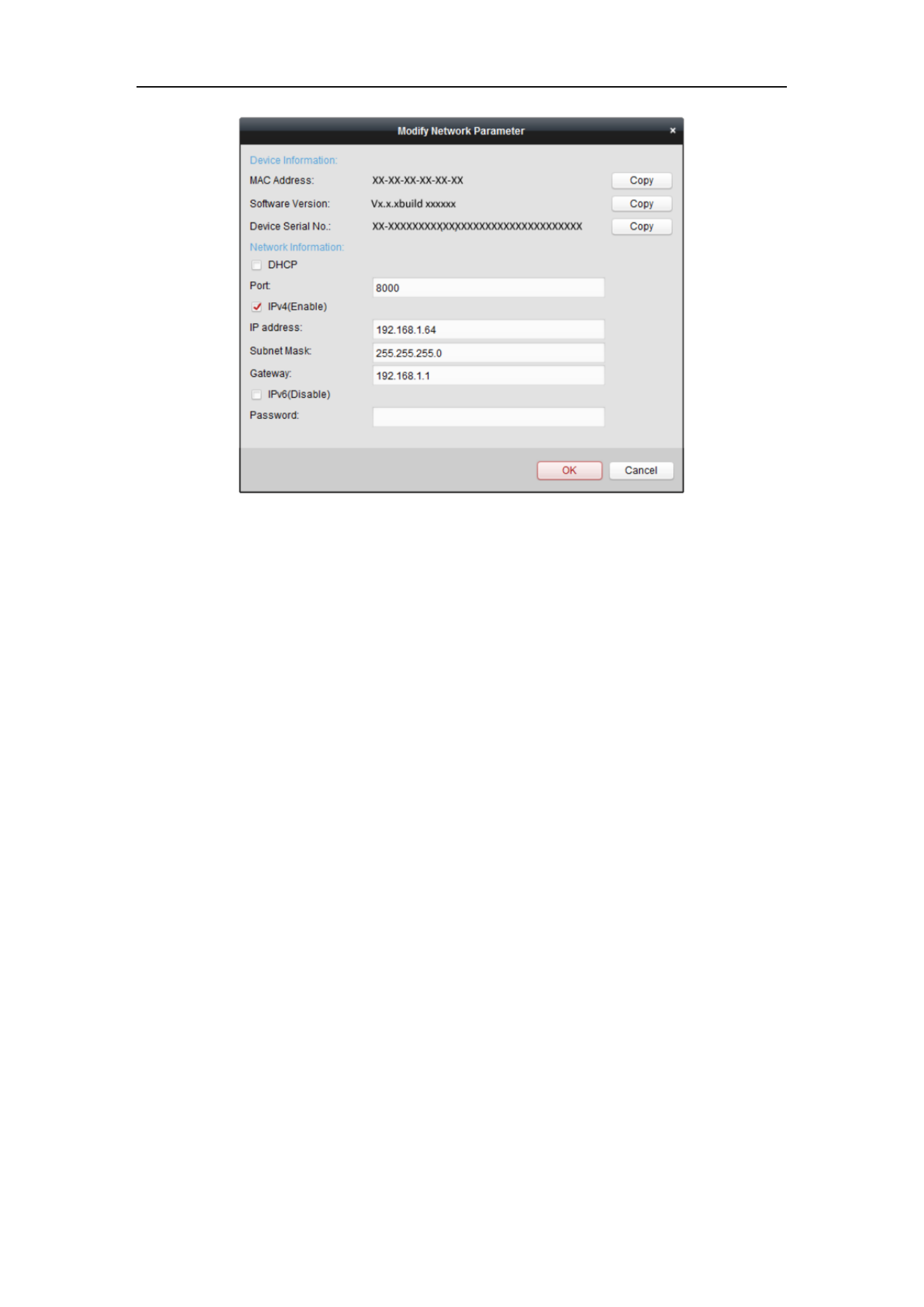
Figure 2-9 Modifying the Network Parameters
8. Change the device IP address to the same subnet with your computer by either
modifying the IP address manually or checking the checkbox of Enable DHCP.
9. Input the password to activate your IP address modification.
2.2 Setting the Network Camera over the WAN
Purpose:
This section explains how to connect the network camera to the WAN with a static IP
or a dynamic IP.
2.2.1 Static IP Connection
Before you start:
Please apply a static IP from an ISP (Internet Service Provider). With the static IP
address, you can connect the network camera via a router or connect it to the WAN
directly.
Connecting the network camera via a router
Steps:
1. Connect the network camera to the router.

User Manual of Network Camera
19
2. Assign a LAN IP address, the subnet mask and the gateway. Refer to Section 2.1.2
for detailed IP address configuration of the network camera.
3. Save the static IP in the router.
4. Set port mapping, e.g., 80, 8000, and 554 ports. The steps for port mapping vary
according to the different routers. Please call the router manufacturer for
assistance with port mapping.
Note: Refer to Appendix 2 for detailed information about port mapping.
5. Visit the network camera through a web browser or the client software over the
internet.
Figure 2-10 Accessing the Camera through Router with Static IP
Connecting the network camera with static IP directly
You can also save the static IP in the camera and directly connect it to the internet
without using a route Refer to Section 2.1.2 for detailed IP address configuration of r.
the network camera.
Figure 2-11 Accessing the Camera with Static IP Directly
2.2.2 Dynamic IP Connection
Before you start:
Please apply a dynamic IP from an ISP. With the dynamic IP address, you can connect
the network camera a modem or a router. to
Connecting the network camera via a router
Steps:

User Manual of Network Camera
20
1. Connect the network camera to the router.
2. In the camera, assign a LAN IP address, the subnet mask and the gateway. Refer
to Section 2.1.2 for detailed IP address configuration of the network camera.
3. In the router, set the PPPoE user name, password and confirm the password.
4. Set port mapping. E.g. 80, 8000, and 554 ports. The steps for port mapping vary
depending on different routers. Please call the router manufacturer for assistance
with port mapping.
Note: Refer to Appendix 2 for detailed information about port mapping.
5. Apply a domain name from a domain name provider.
6. Configure the DDNS settings in the setting interface of the router.
7. Visit the camera via the applied domain name.
Connecting the network camera via a modem
Purpose:
This camera supports the PPPoE auto dial-up function. The camera gets a public IP
address by ADSL dial-up after the camera is connected to a modem. You need to
configure the PPPoE parameters of the network camera. Refer to Section 6.3.3
Configuring PPPoE Settings for detailed configuration.
Figure 2-12 Accessing the Camera with Dynamic IP
Note: The obtained IP address is dynamically assigned via PPPoE, so the IP address
always changes after rebooting the camera. To solve the inconvenience of the
dynamic IP, you need to get a domain name from the DDNS provider (E.g.
DynDns.com). Please follow the steps below for normal domain name resolution and
private domain name resolution to solve the problem.
Normal Domain Name Resolution

User Manual of Network Camera
24
web browser and log in again after installing the plug-in.
3.2 Accessing by Client Software
The product CD contains the iVMS-4200 client software. You can view the live video
and manage the camera with the software.
Follow the installation prompts to install the software. The control panel and live view
interface of iVMS-4200 client software are shown as below.
Figure 3-5 iVMS-4200 Control Panel

User Manual of Network Camera
25
Figure 3-6 iVMS-4200 Main View
Note: For detailed information about the software, please refer to the user manual of
the iVMS-4200.
User Manual of Network Camera
26
Chapter 4 -Fi Settings Wi
Purpose:
By connecting to the wireless network, you don’t need to use cable of any kind for
network connection, which is very convenient for the actual surveillance application.
Note: This chapter is only applicable for the cameras with the built-in Wi-Fi module.
4.1 Configuring Wi-Fi Connection in Manage and
Ad-hoc Modes
Before you start:
A wireless network must be configured.
Wireless Connection in Manage Mode
Steps:
1. Enter the Wi-Fi configuration interface.
Configuration> Advanced Configuration> Network> Wi- Fi
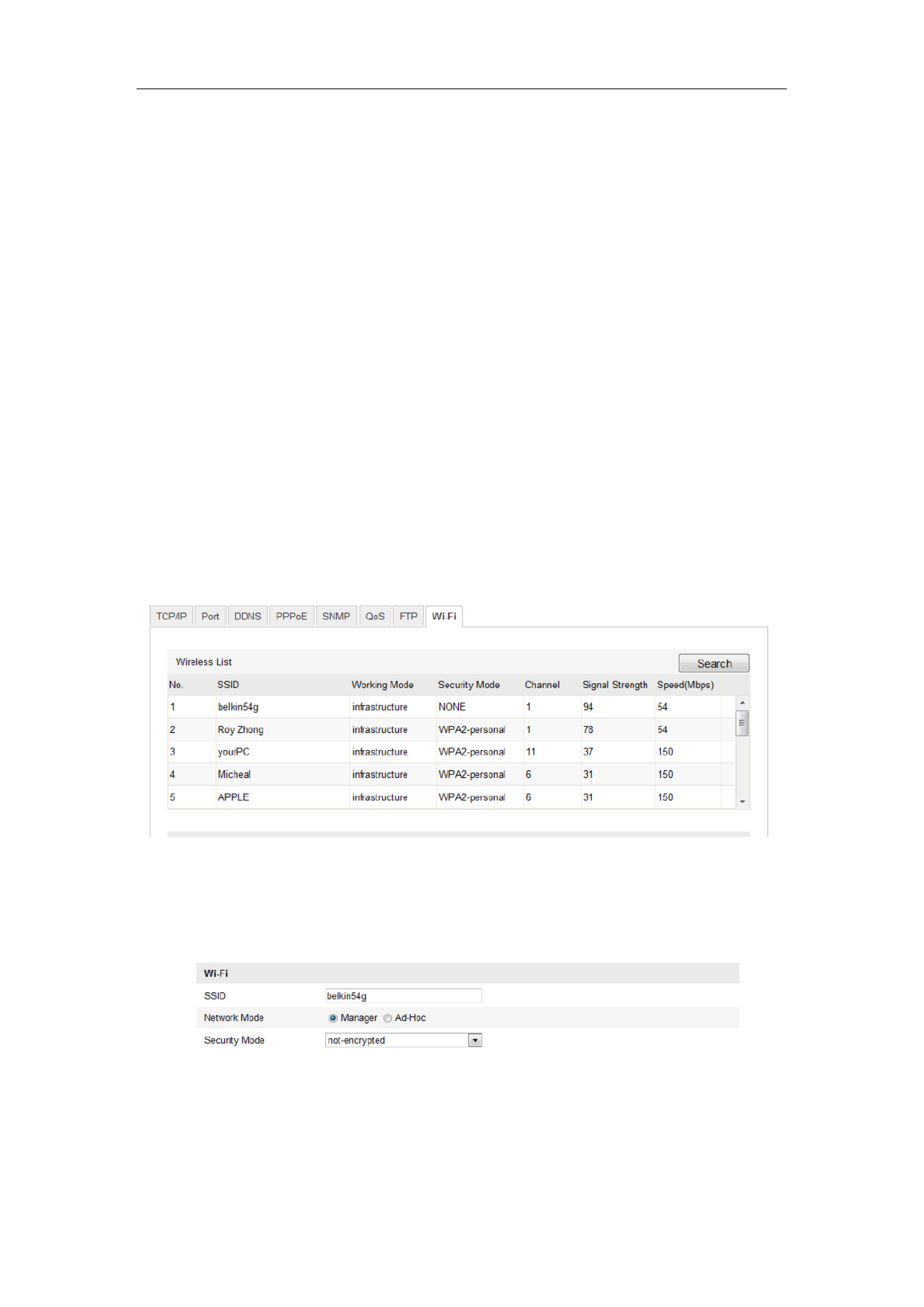
Figure 4-1 Wireless Network List
2. Click Search to search the online wireless connections.
3. Click to choose a wireless connection on the list.
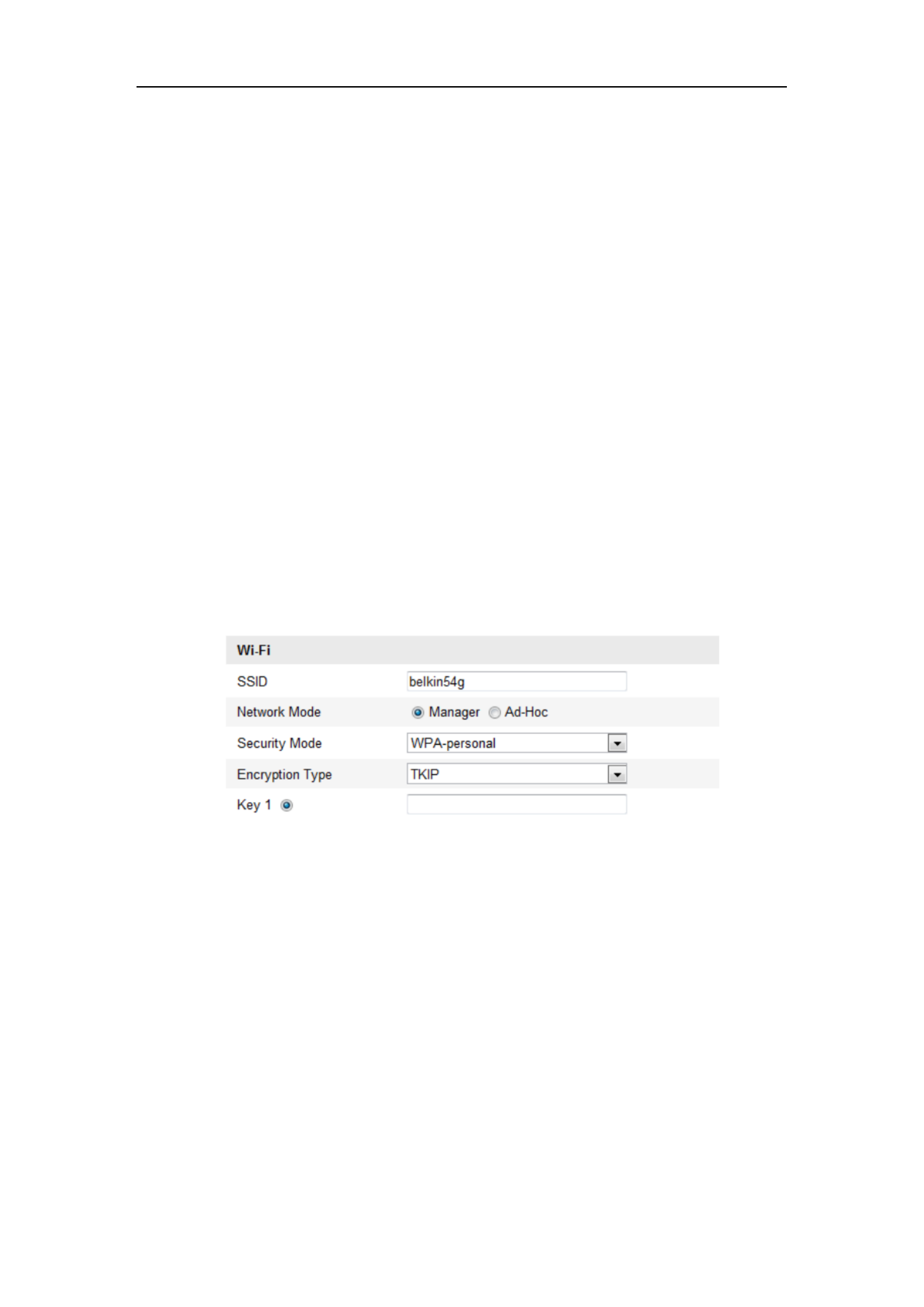
Figure 4-2 -Fi Setting- Manage Mode Wi
User Manual of Network Camera
27
4. Check the checkbox to select the and the Network mode as Manage, Security
mode of the network is automatically shown when you select the wireless
network, please don’t change it manually.
Note: These parameters are exactly identical with those of the router.
5. Enter the key to connect the wireless network. The key should be that of the
wireless network connection you set on the router.
Wireless Connection in Ad-hoc Mode
If you choose the Ad-hoc mode, you don’t need to connect the wireless camera via a
router. The scenario is the same as you connect the camera and the PC directly with a
network cable.
Steps:
1. Choose Ad-hoc mode.
Figure 4-3 -Fi Setting- Wi Ad-hoc
2. Customize a SSID for the camera.
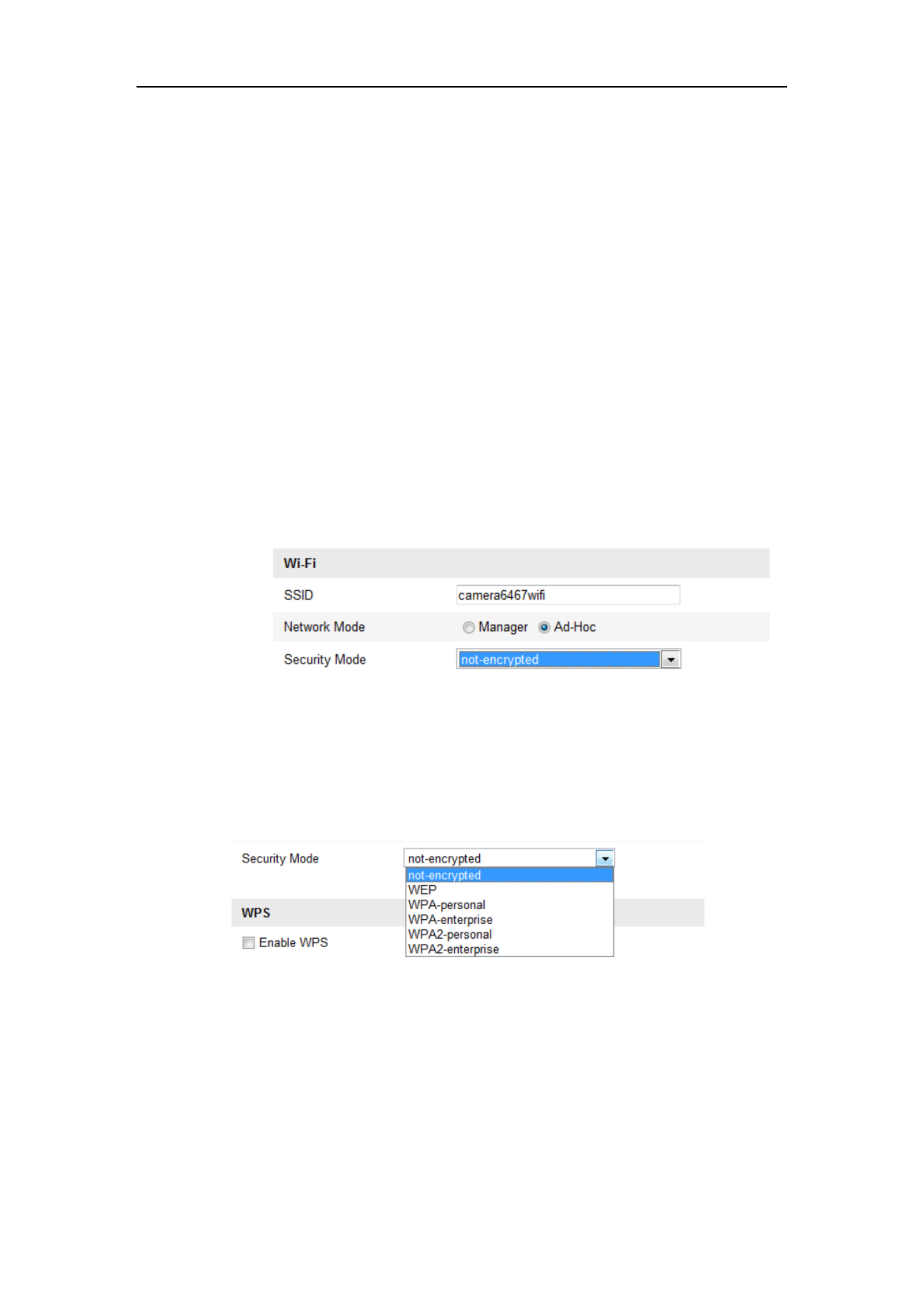
3. Choose the Security Mode of the wireless connection.
Figure 4-4 Security Mode- Ad-hoc Mode
4. able the wireless connection function for your PC. En
5. On the PC side, search the network and you can see the SSID of the camera
listed.

User Manual of Network Camera
28
Figure 4-5 -hoc Connection Point Ad
6. Choose the SSID and connect.
Security Mode Description:
Figure 4-6 Security Mode
You can choose the Security Mode as not-encrypted, WEP, WPA-personal,
WPA-enterprise, WPA2-personal, and WPA2-enterprise.
WEP mode:
Figure 4-7 WEP Mode
Authentication - Select Open or Shared Key System Authentication, depending on
User Manual of Network Camera
29
the method used by your access point. Not all access points have this option, in
which case they probably use Open System, which is sometimes known as SSID
Authentication.
Key length - This sets the length of the key used for the wireless encryption, 64 or
128 bit. The encryption key length can sometimes be shown as 40/64 and
104/128.
Key type - The key types available depend on the access point being used. The
following options are available:
HEX - Allows you to manually enter the hex key.
ASCII - In this method the string must be exactly 5 characters for 64-bit WEP
and 13 characters for 128-bit WEP.
WPA-personal and WPA2-personal Mode:
Enter the required Pre-shared Key for the access point, which can be a hexadecimal
number or a passphrase.
Figure 4-8 Security Mode- WPA-personal
WPA- enterprise and WPA2-enterprise Mode:
Choose the type of client/server authentication being used by the access point;
EAP-TLS or EAP-PEAP.
EAP-TLS

User Manual of Network Camera
30
Figure 4-9 EAP-TLS
Identity - Enter the user ID to present to the network.
Private key password Enter the password for your user ID. –
EAPOL version - Select the version used (1 or 2) in your access point.
CA Certificates - Upload a CA certificate to present to the access point for
authentication.
EAP-PEAP:
User Name - Enter the user name to present to the network
Password - Enter the password of the network
PEAP Version - Select the PEAP version used at the access point.
Label - Select the label used by the access point.
EAPOL version - Select version (1 or 2) depending on the version used at the
access point
CA Certificates - Upload a CA certificate to present to the access point for
authentication
For your privacy and to better protect your system against security risks, we
strongly recommend the use of strong passwords for all functions and network
devices. The password should be something of your own choosing (using a
minimum of 8 characters, including upper case letters, lower case letters,
User Manual of Network Camera
31
numbers and special characters) in order to increase the security of your product.
Proper configuration of all passwords and other security settings is the
responsibility of the installer and/or end-user.
4.2 Easy Wi-Fi Connection with WPS function
Purpose:
The setting of the wireless network connection is never easy. To avoid the complex
setting of the wireless connection you can enable the WPS function.
WPS (Wi-Fi Protected Setup) refers to the easy configuration of the encrypted
connection between the device and the wireless router. The WPS makes it easy to add
new devices to an existing network without entering long passphrases. There are two
modes of the WPS connection, the PBC mode and the PIN mode.
Note: If you enable the WPS function, you do not need to configure the parameters
such as the encryption type and you don’t need to know the key of the wireless
connection.
Steps:
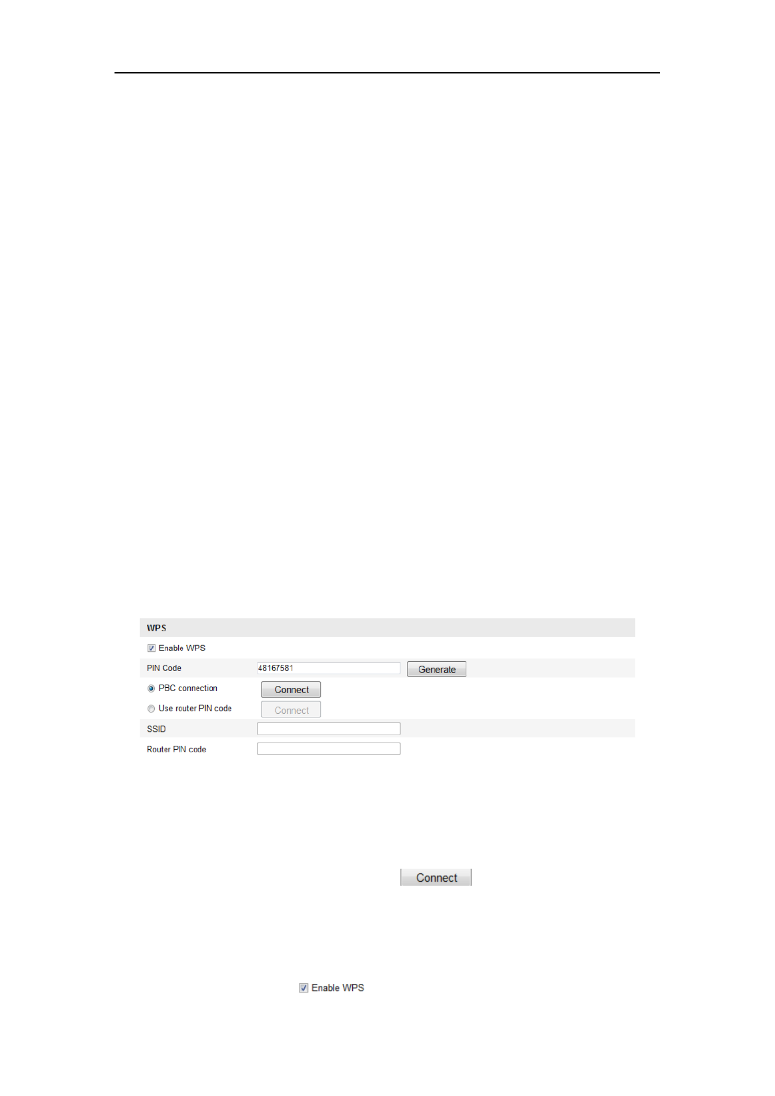
Figure 4-10 -Fi Settings - WPS Wi
PBC Mode:
PBC refers to the Push-Button-Configuration, in which the user simply has to push a
button, either an actual or virtual one (as the button on the configuration
interface of the IE browser), on both the Access Point (and a registrar of the network)
and the new wireless client device.
1. Check the checkbox of to enable WPS.

User Manual of Network Camera
32
2. Choose the connection mode as PBC.
Note: Support of this mode is mandatory for both the Access Points and the
connecting devices.
3. Check on the Wi-Fi router to see if there is a WPS button. If yes push the button
and you can see the indicator near the button start flashing, which means the WPS
function of the router is enabled. For detailed operation, please see the user guide of
the router.
4. Push the WPS button to enable the function on the camera.
If there is not a WPS button on the camera, you can also click the virtual button to
enable the PBC function on the web interface.
5. Click button. Connect
When the PBC mode is both enabled in the router and the camera, the camera and the
wireless network is connected automatically.
PIN Mode:
The PIN mode requires a Personal Identification Number (PIN) to be read from either
a sticker or the display on the new wireless device. This PIN must then be entered to
connect the network, usually the Access Point of the network.
Steps:
1. Choose a wireless connection on the list and the SSID is shown.

User Manual of Network Camera
33
Figure 4-11 -Fi Settings WPS PIN Mode Wi –
2. Choose Use route PIN code.
If the PIN code is generated from the router side, you should enter the PIN code you
get from the router side in the Router PIN code field.
3. Click . Connect
Or
You can generate the PIN code on the camera side. And the expired time for the PIN
code is 120 seconds.
1. Click . Generate
2. Enter the code to the router, in the example, enter 48167581 to the route r.
4.3 IP Property Settings for Wireless Network
Connection
The default IP address of wireless network interface controller is 192.168.1.64. When
you connect the wireless network you can change the default IP.
Steps:

User Manual of Network Camera
34
1. Enter the TCP/IP configuration interface.
Configuration> Advanced Configuration> Network> TCP/IP
Or
Configuration> Basic Configuration> Network> TCP/IP
Figure 4-12 TCP/IP Settings
2. Select the NIC as wlan.
3. Customize the IPv4 address, the IPv4 Subnet Mask and the Default Gateway.
The setting procedure is the same with that of LAN.
If you want to be assigned the IP address you can check the checkbox to enable the
DHCP.

User Manual of Network Camera
100
1. Enter the Line Crossing Detection settings interface:
Configuration> Advanced Configuration> Sma Event> Line Crossing rt
Detection
2. Check the checkbox of to enable the function. Enable Line Crossing Detection
3. Select the line from the drop-down list for detection settings.
4. Click the button, and a virtual line is displayed on the live video. Draw Area
5. ick-and-drag the line, and you can locate it on the live video as desired. Click Cl
on the line, two red squares are displayed on each end, and you can
click-and-drag one of the red squares to define the shape and length of the line.
6. Select the direction for line crossing detection. And you can select the directions
as A<->B, A ->B, and B->A.
A<->B: Only the arrow on the B side shows; when an object going across the plane
with both direction can be detected and alarms are triggered.
A->B: Only the object crossing the configured line from the A side to the B side
can be detected.
B->A: Only the object crossing the configured line from the B side to the A side
can be detected.
7. Click-and-drag the slider to set the detection sensitivity.
Sensitivity: Range [1-100]. The higher the value is, the more easily the line
crossing action can be detected.
8. Repeat the above steps to configure other lines. Up to 4 lines can be set. You can
click the button to clear all pre-defined lines. Clear
9. Click the button to set the arming schedule. Edit
10. Select the linkage methods for line crossing detection, including Notify
Surveillance Center, Send Email, Upload to FTP, Trigger Channel and Trigger
Alarm Output.
11. Click to save the settings. Save

User Manual of Network Camera
101
Figure 6-62 Draw Crossing Line
6.6.12 Configuring Intrusion Detection
Purpose:
Intrusion detection function detects people, vehicle or other objects which enter and
loiter in a pre-defined virtual region, and some certain actions can be taken when the
alarm is triggered.
Note: Intrusion detection function varies according to different camera models.
Steps:
1. Enter the Intrusion Detection settings interface:
Configuration> Advanced Configuration> Smart Event> Intrusion Detection
2. Check the checkbox of to enable the function. Enable Intrusion Detection
3. Select the region from the drop-down list for detection settings.
4. Click the button to start the region drawing. Draw Area
5. Click on the live video to specify the four vertexes of the detection region, and
right click to complete drawing.

User Manual of Network Camera
102
6. Set the time threshold, detection sensitivity and object percentage for intrusion
detection.
Threshold: Range [0s-10s], the threshold for the time of the object loitering in
the region. If you set the value as 0, alarm is triggered immediately after the
object entering the region.
Sensitivity: Range [1-100]. The value of the sensitivity defines the size of the
object which can trigger the alarm. When the sensitivity is high, a very small
object can trigger the alarm.
Percentage: Range [1-100]. Percentage defines the ratio of the in-region part of
the object which can trigger the alarm. For example, if the percentage is set as
50%, when the object enters the region and occupies half of the whole region, the
alarm is triggered.
7. Repeat the above steps to configure other regions. Up to 4 regions can be set. You
can click the button to clear all pre-defined regions. Clear
8. Click the button to set the arming schedule. Edit
9. Select the linkage methods for intrusion detection, including Notify Surveillance
Center, Send Email, Upload to FTP, Trigger Channel and Trigger Alarm Output.
10. Click to save the settings. Save
Figure 6-63 Configuring Intrusion Area

User Manual of Network Camera
105
object which can trigger the alarm. When the sensitivity is high, a very small
object exiting from the region can trigger the alarm.
7. Repeat the above steps to configure other regions. Up to 4 regions can be set. You
can click the button to clear all pre-defined regions. Clear
8. Click the button to set the arming schedule. Edit
9. Select the linkage methods for region exiting detection, including Notify
Surveillance Center, Send Email, Upload to FTP, Trigger Channel and Trigger
Alarm Output.
10. Click to save the settings. Save
Figure 6-65 Configuring Region Exiting Detection
6.6.15 Configuring Unattended Baggage Detection
Purpose:
Unattended baggage detection function detects the objects left over in the pre-defined
region such as the baggage, purse, dangerous materials, etc., and a series of actions
can be taken when the alarm is triggered.
Note: Unattended baggage detection function varies according to different camera
models.
Steps:

User Manual of Network Camera
106
1. Enter the Unattended Baggage Detection settings interface:
Configuration> Advanced Configuration> Smart Event> Unattended
Baggage Detection
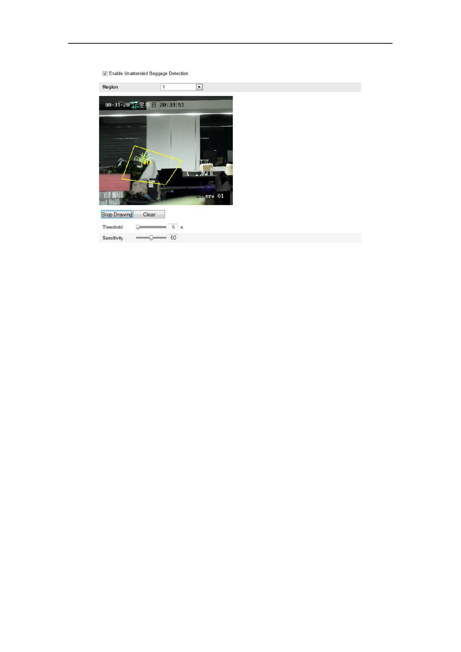
2. Check the checkbox of to enable the Enable Unattended Baggage Detection
function.
3. Select the region from the drop-down list for detection settings.
4. Click the button to start the region drawing. Draw Area
5. Click on the live video to specify the four vertexes of the detection region, and
right click to complete drawing.
6. Set the time threshold and detection sensitivity for unattended baggage detection.
Threshold: Range [5s- s], the threshold for the time of the objects left over in 20
the region. If you set the value as 10, alarm is triggered after the object is left and
stay in the region for 10s.
Sensitivity: Range [1-100]. The value of sensitivity defines the similarity degree
of the background image. Usually, when the sensitivity is high, a very small
object left in the region can trigger the alarm.
7. Repeat the above steps to configure other regions. Up to 4 regions can be set. You
can click the button to clear all pre-defined regions. Clear
8. Click the button to set the arming schedule. Edit
9. Select the linkage methods for unattended baggage detection, including Notify
Surveillance Center, Send Email, Upload to FTP, Trigger Channel and Trigger
Alarm Output.
10. Click to save the settings. Save
User Manual of Network Camera
107
Figure 6-66 Configuring Unattended Baggage
6.6.16 Configuring Object Removal Detection
Purpose:
Object removal detection function detects the objects removed from the pre-defined
region, such as the exhibits on display, and a series of actions can be taken when the
alarm is triggered.
Note: Object removal detection function varies according to different camera models.
Steps:
1. Enter the Object Removal Detection settings interface:
Configuration> Advanced Configuration> Smart Event> Object Removal
Detection
2. Check the checkbox of to enable the Enable Object Removal Detection
function.
3. Select the region from the drop-down list for detection settings.
4. Click the button to start the region drawing. Draw Area
5. Click on the live video to specify the four vertexes of the detection region, and
right click to complete drawing.

User Manual of Network Camera
108
6. Set the time threshold and detection sensitivity for object removal detection.
Threshold: Range [5s-20 , the threshold for the time of the objects removed s]
from the region. If you set the value as 10, alarm is triggered after the object
disappears from the region for 10s.
Sensitivity: Range [1-100]. The value of sensitivity defines the similarity degree
of the background image. Usually, when the sensitivity is high, a very small
object taken from the region can trigger the alarm.
7. Repeat the above steps to configure other regions. Up to 4 regions can be set. You
can click the button to clear all pre-defined regions. Clear
8. Click the button to set the arming schedule. Edit
9. Select the linkage methods for object removal detection, including Notify
Surveillance Center, Send Email, Upload to FTP, Trigger Channel and Trigger
Alarm Output.
10. Click to save the settings. Save
Figure 6-67 Configuring Object Removal Detection

User Manual of Network Camera
109
6.7 VCA Configuration
6.7.1 Behavior Analysis
The behavior analysis detects a series of suspicious behavior, and certain linkage
methods will be enabled if the alarm is triggered.
Figure 6-68 Behavior Analysis
VCA Info
Behavior Analysis Version: It lists the version of the algorithms library.
Display information includes the display on picture and display on stream.
Display Target info. on Alarm Picture: There will be a fram on the target on e
the uploaded alarm picture if the checkbox is checked.
Display Rule info. on Alarm Picture: The captured target and the configured
area will be framed on the alarm picture.
Display VCA info. on Stream: The green frames will be displayed on the target
if in a live view or playback.
Note: Make sure the rules are enabled in your local settings. Go to
Configuration Local Configuration Rules > > to enable it.
Snapshot Setting: You can set the quality and resolution for the captured picture.
Upload JPEG Image to Center: Check the checkbox to upload the captured

User Manual of Network Camera
110
image to the surveillance center when a VCA alarm occurs.
Picture Quality: High, Medium and Low are selectable.
Picture Resolution: CIF, 4CIF, 720P, and 1080P are selectable.
Camera Calibration
Perform the following steps to three-dimensionally measure and quantize the image
from the camera, and then calculate the size of every target. The VCA detection will
be more accurate if the camera calibration is configured.
Steps:
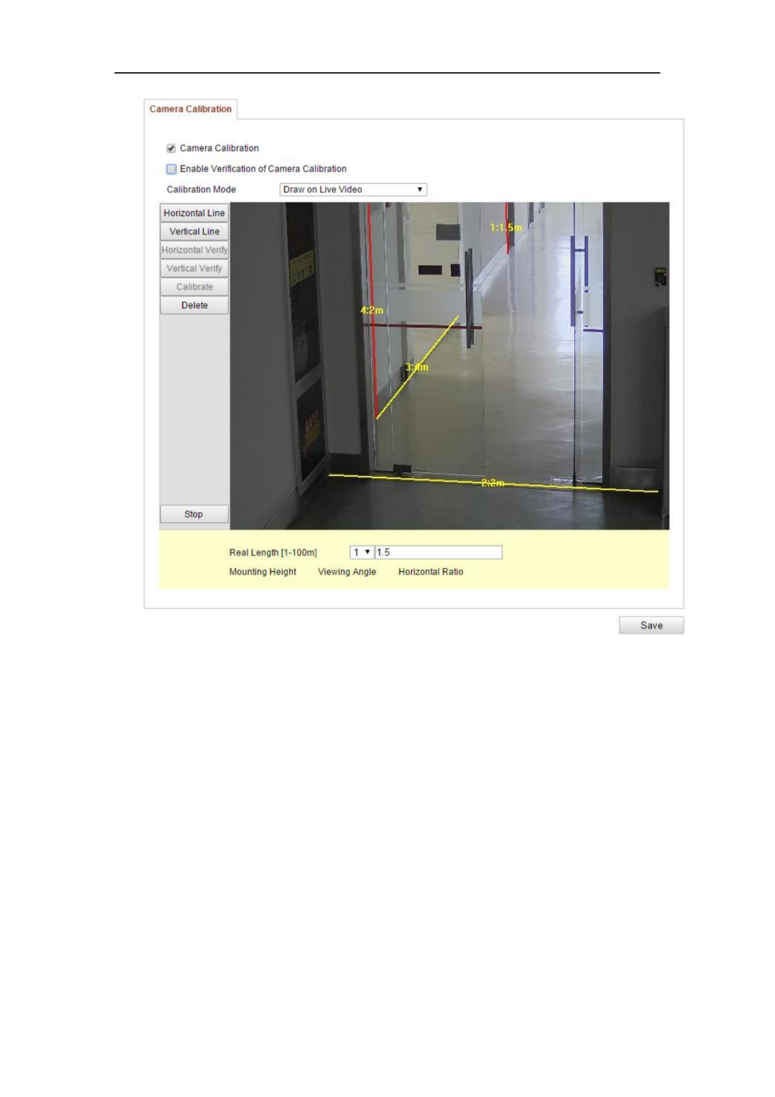
1. Check the checkbox of to enable this function. Camera Calibration
2. Select the calibration mode as Input Basic Data or Draw on Live View Video.
Input Basic Data: Input the mounting height, viewing angle, and horizon
ratio of the camera manually.
Draw on Live View Video Draw Verification Line (Horizontal) : Click /
(Vertical) to draw a horizontal/vertical line in the live view, and input the
actual length in Real Length field. With the drawn reference lines and their
real length, the camera can conclude other objects appear in the live view.
3. (Optional) Check the checkbox of Enable Verification of Camera
Calibration Horizontal Verify / Vertical Verify, click the button to draw a
horizontal / vertical line on the live video, and then click the button Calibrate
to calculate the line length. Compare the calculated line length to the actual
length to verify the calibration information you set.
4. You can click to delete the drawn lines. Delete
5. Click to save the settings. Save
Note: If the live view is stopped, the camera calibration is invalid.
User Manual of Network Camera
111
Figure 6-69 Draw on Live View Window
Shield Region
The shield region allows you to set the specific region in which the behavior analysis
will not function. Up to 4 shield regions are supported.
Steps:
1. Click tab to enter the shield region configuration interface. Shield Region
2. Click Draw Area. Draw area by left click end-points in the live view window,
and right click to finish the area drawing.
Notes:
Polygon area with up to 10 sides is supported.
Click to delete the drawn areas.Delete
If live view is stopped, there is no way to draw the shield regions.

User Manual of Network Camera
113
Steps:
1. Click Tab to enter the rule configuration interface. Rule
2. Check the checkbox of the single rule to enable the rule for behavior analysis.
3. Select the rule type, set the filter type, and then draw the line / area on the live
video for the single rule.
Filter type: Pixels and Actual Size are selectable. If Pixels is selected, draw
the area of maximum size and minimum size on the live video for each rule.
If Actual Size is selected, input the length and width of the maximum size and
minimum size. Only the target whose size is between the minimum value and
maximum value will trigger the alarm.
Note: Make sure the camera calibration is configured if actual size is selected.
Detection Target: Select Human or Vehicle as the detection target. You can
also select All to detect all the objects as the target.
Draw line / area: For line crossing detection, you have to draw a line, and
select the crossing direction, which is bidirectional, A- -B, or B- -A. For to to
other events such as intrusion, region entrance, region exiting, etc., you have
to left click on the live video to set the end points of the area and right click to
finish the area drawing.
Note: If the live view is stopped, the detection area / line cannot be draw and
the rules cannot be set.
4. Check the checkbox of the combined rule to enable the rule for behavior
analysis.
5. Select two configured single rules as the Rule A and Rule B of the combined
rule, set the minimum and maximum time interval for the two single rules,
and then select the trigger order of the single rules for alarm filtering.
Notes:
If you select the rule type as None, the rule option is invalid, and no
behavior analysis can be configured.
The trigger order of the single rules for alarm filtering can be set as In
Ascending Order or In Ascending/Descending Order.
Up to 8 single rules and 2 combined rules are configurable. And the line
crossing, intrusion, region exiting and region entrance are supported for
the combined rules.
User Manual of Network Camera
114
6. Click to save the settings. Save
7. Click tab, click to set the schedule time for each rule, Arming Schedule Edit
and click to save the settings. Save
8. Click tab, check the checkbox of corresponding linkage Alarm Linkage
method for each rule, and click to save the settings. Save
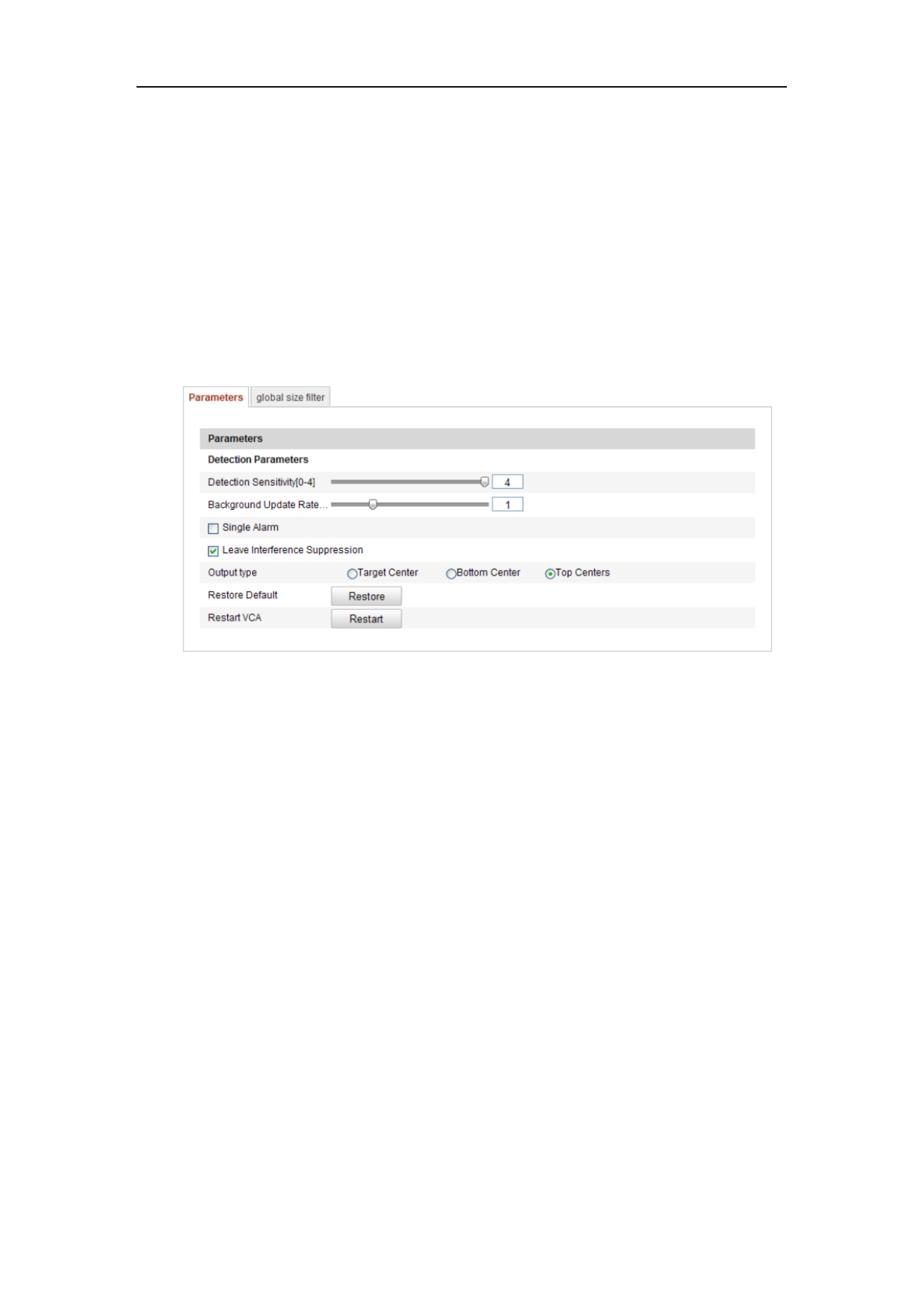
Advanced Configuration
● Parameter
Configure the following parameters to detail the configuration.
Figure 6-71 Advanced Configuration
Detection Sensitivity [0~4]: Refers to the sensitivity of the camera detects a target.
The higher the value, the easier a target be recognized, and the higher the
misinformation is. The default value of 3 is recommended.
Background Update Rate [0~4]: It refers to the speed of the new scene replaces the
previous scene. The default value of 3 is recommended.
Single Alarm : If single alarm is selected, the target in the configured area will trigger
the alarm for only once. If it is not checked, the same target will cause the continuous
alarm in the same configured area.
Leave Interference Suppression: Check this checkbox to stop the interference
caused by the leaves in the configured area.
Output Type: Select the position of the frame. Target center, bottom center, and top
centers are selectable. E.g.: The target will be in the center of the frame if target center
is selected.

User Manual of Network Camera
115
Restore Default: Click to restore the configured parameters to the default.
Restart VCA: Restart the algorithms library of behavior analysis.
● Global Size Filter
Note: Compared with the size filter under rule, which is aiming at each
rule, the global size filter is aim at all rules.
Steps:
1. Check the checkbox of to enable the function. Global Size Filter
2. Select the Filter Type as Actual Size or Pixel.
Actual Size: Input the length and width of both the maximum size and the
minimum size. Only the target whose size is between the minimum value and
maximum value will trigger the alarm.
Notes:
● Camera calibration has to be configured if you select the filter by actual
size.
● The length of the maximum size should be longer than the length of the
minimum size, and so does the width.
Pixel: Click Minimum Size to draw the rectangle of the min. size on the live view.
And click Maximum Size to draw the rectangle of the max. size on the live view.
The target is smaller than the min. size or larger than the max. size will be
filtered.
Notes:
● The drawn area will be convert to the pixel by the background ed
algorithm.
● The global size filter cannot be configured if the live view is stopped.
● The length of the maximum size should be longer than the length of the
minimum size, and so does the width.
3. Click to save the settings. Save

User Manual of Network Camera
116
6.7.2 Face Capture
Face capture can capture the face appears in the configured area, and the face
characters information, including the age, gender, and wearing glasses or not will be
uploaded with the captured picture as well.
Figure 6-72 Face Capture
VCA Info
Face Capture Version: It lists the version of the algorithms library.
Display information includes the display on picture and display on stream.
Display Target info. on Alarm Picture: There will be a frame on the target on
the uploaded alarm picture if the checkbox is checked.
Display VCA info. on Stream: The green frames will be displayed on the target
if in a live view or playback.
Snapshot Setting: Select the picture quality for the captured picture. Good, better, and
best are selectable.
Shield Region
The shield region allows you to set the specific region in which the face capture will
not function. Up to 4 shield regions are supported.
Steps:
1. Click tab to enter the shield region configuration interface. Shield Region
2. Click Draw Area. Draw area by left click four end-points in the live view
window, and right click to finish the area drawing.

User Manual of Network Camera
117
Notes:
● Click to delete the drawn areas.Delete
● If the live view is stopped, there is no way to draw the shield
regions.
3. Click to save the settings. Save
Rule
Steps:
1. Check the checkbox of to enable rules of face capture. Rule
2. Click to draw the minimum pupil distance. The Minimize Pupil Distance
distance of the drawn pupil will be displayed on the box below the live view.
The minimize pupil distance refers to the minimum square size composed by
the area between two pupils, and it is the basic standard for a camera to
identify a target.
3. Click Draw Area to draw the area you want the face capture to take effect.
Draw area by left click end-points in the live view window, and right click to
finish the area drawing.
Note s:
Polygon area (4~10 sides) sides is supported.
If the live view is stopped, there is no way to draw the configured area.
4. Click to save the settings. Save
Advanced Configuration
Configure the following parameters according to your actual environment.
Detection Parameters:
Generation Speed [1~5]: The speed to identify a target. The higher the value, the
fast the target will be recognized. Setting the value quite low, and if there was a face er
in the configured area from the start, this face will not be captured. It can reduce the
misinformation of the faces in the wall painting or posters. The default value of 3 is
recommended.
Capture Times [1~10]: Refers to the capture times a face will be captured during its
stay in the configured area. The default value is 1.
Sensitivity [1~5]: The sensitivity to identify a target. The higher the value, the easier
a face will be recognized, and the higher misinformation is. The default value of 3 is

User Manual of Network Camera
118
recommended.
Capture Interval [1~255 Frame]: The frame interval to capture a picture. If you set
the value as 1, which is the default value, it means the camera captures the face in
every frame.
Capture Sensitivity [0~20]: The threshold the camera treats the target as a face. Only
when the face score generated by the algorithm is equal or higher than the value, the
camera will treat the target as a face. The default value of 2 is recommended.
Face Capture Advanced Parameters:
Face Exposure: Check the checkbox to enable the face exposure.
Reference Brightness [0~100]: The reference brightness of a face in the face
exposure mode. If a face is detected, the camera adjusts the face brightness according
to the value you set. The higher the value, the brighter the face is.
Minimum Duration [1~60min]: The minimum duration of the camera exposures the
face. The default value is 1 minute.
Note: If the face exposure is enabled, please make sure the WDR function is disabled,
and the manual iris is selected.
Enable Face ROI: If the camera captures a face, the face area will be treated as the
region of interest, and the image quality of this area will be improved.
Restore Default Restore : Click to restore all the settings in advanced configuration
to the factory default.

User Manual of Network Camera
120
Figure 6-74 Heat Map Configuration
2. Select tab to set the detailed parameters. Heat Map Configuration
3. Check the checkbox of to enable the function. Enable Heat Map
4. Click Draw Area to define the area for heat value statistics. Draw area by left
click four end-points in the live view window, and right click to finish the area
drawing. Up to 8 areas are configurable.
Note: You can click Select All to select the whole live view window as the
configured area. Or click to delete the current drawn area.Delete
5. Configure the parameters for drawn area.
Detection Sensitivity [0~100]: It refers to the sensitivity of the camera
identify a target. The over-high sensitivity may cause the misinformation. It is
recommended you set the sensitivity as the default value, which is 50.
Background Update Rate [0~100]: It refers to the speed of the new scene
replaces the previous scene. E.g.: In front of a cabinet, the people besides the
cabinet will be double counted if the goods moved from the cabinet, and the
camera treats the cabinet (on which the good removed) as a new scene. The
default value of 50 is recommended.
Scene Change Level [0~100]: It refers to level of the camera responses to the
dynamic environment, e.g., a swaying curtain. The camera may treat the
swaying curtain as a target. Setting the level properly will avoid the
Produktspecifikationer
| Varumärke: | Hikvision |
| Kategori: | övervakningskamera |
| Modell: | DS-2CD2942F |
Behöver du hjälp?
Om du behöver hjälp med Hikvision DS-2CD2942F ställ en fråga nedan och andra användare kommer att svara dig
övervakningskamera Hikvision Manualer

5 April 2025
5 April 2025
5 April 2025
8 Januari 2025
8 Januari 2025
8 Januari 2025
8 Januari 2025
7 Januari 2025
19 December 2024
19 December 2024
övervakningskamera Manualer
- övervakningskamera Sony
- övervakningskamera Samsung
- övervakningskamera Xiaomi
- övervakningskamera Bosch
- övervakningskamera Braun
- övervakningskamera Philips
- övervakningskamera Panasonic
- övervakningskamera Grundig
- övervakningskamera Gigaset
- övervakningskamera Honeywell
- övervakningskamera JVC
- övervakningskamera Motorola
- övervakningskamera Toshiba
- övervakningskamera VTech
- övervakningskamera Canon
- övervakningskamera Abus
- övervakningskamera Ag Neovo
- övervakningskamera Allnet
- övervakningskamera Alecto
- övervakningskamera Apc
- övervakningskamera Aldi
- övervakningskamera Aluratek
- övervakningskamera Airlive
- övervakningskamera Anker
- övervakningskamera Aritech
- övervakningskamera Acti
- övervakningskamera ACME
- övervakningskamera Edimax
- övervakningskamera Strong
- övervakningskamera Flamingo
- övervakningskamera Nedis
- övervakningskamera Thomson
- övervakningskamera Gembird
- övervakningskamera Yale
- övervakningskamera Pyle
- övervakningskamera SereneLife
- övervakningskamera Eminent
- övervakningskamera Avanti
- övervakningskamera Renkforce
- övervakningskamera Kodak
- övervakningskamera Overmax
- övervakningskamera Niceboy
- övervakningskamera Sitecom
- övervakningskamera Blaupunkt
- övervakningskamera TP Link
- övervakningskamera Megasat
- övervakningskamera Logitech
- övervakningskamera Manhattan
- övervakningskamera Exibel
- övervakningskamera Ezviz
- övervakningskamera Trust
- övervakningskamera Fortinet
- övervakningskamera Elro
- övervakningskamera EMOS
- övervakningskamera Extech
- övervakningskamera KlikaanKlikuit
- övervakningskamera Denver
- övervakningskamera DataVideo
- övervakningskamera Schneider
- övervakningskamera Axis
- övervakningskamera Sanyo
- övervakningskamera Vitek
- övervakningskamera Imou
- övervakningskamera Hama
- övervakningskamera Maginon
- övervakningskamera Mitsubishi
- övervakningskamera Velleman
- övervakningskamera Smartwares
- övervakningskamera Profile
- övervakningskamera Marquant
- övervakningskamera Trebs
- övervakningskamera Ednet
- övervakningskamera Cisco
- övervakningskamera AVerMedia
- övervakningskamera Eufy
- övervakningskamera Steren
- övervakningskamera Perel
- övervakningskamera Engenius
- övervakningskamera Burg-Wachter
- övervakningskamera Lumens
- övervakningskamera Flir
- övervakningskamera Somfy
- övervakningskamera Netis
- övervakningskamera Genius
- övervakningskamera Adj
- övervakningskamera Digitus
- övervakningskamera Olympia
- övervakningskamera Belkin
- övervakningskamera Linksys
- övervakningskamera Buffalo
- övervakningskamera Uniden
- övervakningskamera Dahua Technology
- övervakningskamera Ion
- övervakningskamera GeoVision
- övervakningskamera Arlo
- övervakningskamera Netgear
- övervakningskamera Nest
- övervakningskamera LevelOne
- övervakningskamera DIO
- övervakningskamera Boss
- övervakningskamera Siedle
- övervakningskamera Ricoh
- övervakningskamera Hive
- övervakningskamera Netatmo
- övervakningskamera Marshall
- övervakningskamera Switel
- övervakningskamera Chacon
- övervakningskamera InFocus
- övervakningskamera Hombli
- övervakningskamera Reolink
- övervakningskamera First Alert
- övervakningskamera UniView
- övervakningskamera Planet
- övervakningskamera ZyXEL
- övervakningskamera Western Digital
- övervakningskamera Clas Ohlson
- övervakningskamera Naxa
- övervakningskamera Konig
- övervakningskamera Valueline
- övervakningskamera Trevi
- övervakningskamera Foscam
- övervakningskamera BRK
- övervakningskamera Orion
- övervakningskamera Zebra
- övervakningskamera EVE
- övervakningskamera Technaxx
- övervakningskamera D-Link
- övervakningskamera Swann
- övervakningskamera Withings
- övervakningskamera Tenda
- övervakningskamera QSC
- övervakningskamera Xavax
- övervakningskamera Marmitek
- övervakningskamera Minox
- övervakningskamera Delta Dore
- övervakningskamera M-e
- övervakningskamera Lorex
- övervakningskamera Ubiquiti Networks
- övervakningskamera Marshall Electronics
- övervakningskamera Vaddio
- övervakningskamera Gira
- övervakningskamera Jung
- övervakningskamera Interlogix
- övervakningskamera Ring
- övervakningskamera Trendnet
- övervakningskamera DSC
- övervakningskamera Boyo
- övervakningskamera Laserliner
- övervakningskamera Iget
- övervakningskamera CRUX
- övervakningskamera Conceptronic
- övervakningskamera EverFocus
- övervakningskamera Adesso
- övervakningskamera Satel
- övervakningskamera Vivotek
- övervakningskamera Notifier
- övervakningskamera Lanberg
- övervakningskamera Friedland
- övervakningskamera Nexxt
- övervakningskamera Revo
- övervakningskamera Quantum
- övervakningskamera Monoprice
- övervakningskamera Broan
- övervakningskamera Avidsen
- övervakningskamera Furrion
- övervakningskamera Beafon
- övervakningskamera SPC
- övervakningskamera Stabo
- övervakningskamera Crestron
- övervakningskamera Chuango
- övervakningskamera ORNO
- övervakningskamera ETiger
- övervakningskamera INSTAR
- övervakningskamera Grandstream
- övervakningskamera Provision ISR
- övervakningskamera Monacor
- övervakningskamera Logilink
- övervakningskamera Aqara
- övervakningskamera Moxa
- övervakningskamera Advantech
- övervakningskamera Digital Watchdog
- övervakningskamera Ferguson
- övervakningskamera Ganz
- övervakningskamera MEE Audio
- övervakningskamera Kwikset
- övervakningskamera Elmo
- övervakningskamera Intellinet
- övervakningskamera ClearOne
- övervakningskamera Ebode
- övervakningskamera Oplink
- övervakningskamera Kerbl
- övervakningskamera Dorr
- övervakningskamera Sonic Alert
- övervakningskamera Linear PRO Access
- övervakningskamera BirdDog
- övervakningskamera AVer
- övervakningskamera Summer Infant
- övervakningskamera SMC
- övervakningskamera Topica
- övervakningskamera Vimar
- övervakningskamera Kogan
- övervakningskamera Iiquu
- övervakningskamera Speco Technologies
- övervakningskamera Verint
- övervakningskamera ZKTeco
- övervakningskamera Brinno
- övervakningskamera Raymarine
- övervakningskamera Rostra
- övervakningskamera Caddx
- övervakningskamera Spyclops
- övervakningskamera Schwaiger
- övervakningskamera EKO
- övervakningskamera Inovonics
- övervakningskamera Kguard
- övervakningskamera Woonveilig
- övervakningskamera Mobi
- övervakningskamera V-Tac
- övervakningskamera Surveon
- övervakningskamera Hollyland
- övervakningskamera Epcom
- övervakningskamera EVOLVEO
- övervakningskamera Indexa
- övervakningskamera AViPAS
- övervakningskamera Kramer
- övervakningskamera Lutec
- övervakningskamera Whistler
- övervakningskamera Hanwha
- övervakningskamera ClearView
- övervakningskamera VideoComm
- övervakningskamera IMILAB
- övervakningskamera 3xLOGIC
- övervakningskamera Pelco
- övervakningskamera Leviton
- övervakningskamera EtiamPro
- övervakningskamera Inkovideo
- övervakningskamera Pentatech
- övervakningskamera Weldex
- övervakningskamera SecurityMan
- övervakningskamera Brilliant
- övervakningskamera Lindy
- övervakningskamera Canyon
- övervakningskamera CNB Technology
- övervakningskamera Tapo
- övervakningskamera Aigis
- övervakningskamera Exacq
- övervakningskamera Brickcom
- övervakningskamera Laxihub
- övervakningskamera Securetech
- övervakningskamera EFB Elektronik
- övervakningskamera Ernitec
- övervakningskamera NetMedia
- övervakningskamera Videotec
- övervakningskamera Illustra
- övervakningskamera Atlona
- övervakningskamera AVMATRIX
- övervakningskamera Nivian
- övervakningskamera Arenti
- övervakningskamera E-bench
- övervakningskamera Blow
- övervakningskamera Syscom
- övervakningskamera Tecno
- övervakningskamera Night Owl
- övervakningskamera Guardzilla
- övervakningskamera Astak
- övervakningskamera Blink
- övervakningskamera Milestone Systems
- övervakningskamera Zavio
- övervakningskamera Campark
- övervakningskamera IPX
- övervakningskamera Dedicated Micros
- övervakningskamera Hamlet
- övervakningskamera Equip
- övervakningskamera Annke
- övervakningskamera AVTech
- övervakningskamera Qoltec
- övervakningskamera Approx
- övervakningskamera Digimerge
- övervakningskamera Y-cam
- övervakningskamera Alfatron
- övervakningskamera Feelworld
- övervakningskamera KJB Security Products
- övervakningskamera Wisenet
- övervakningskamera BZBGear
- övervakningskamera WyreStorm
- övervakningskamera Infortrend
- övervakningskamera Epiphan
- övervakningskamera HiLook
- övervakningskamera Mach Power
- övervakningskamera Compro
- övervakningskamera Aida
- övervakningskamera Ikegami
- övervakningskamera Accsoon
- övervakningskamera Vimtag
- övervakningskamera Sonoff
- övervakningskamera Gewiss
- övervakningskamera Alula
- övervakningskamera Insteon
- övervakningskamera Costar
- övervakningskamera ALC
- övervakningskamera Security Labs
- övervakningskamera Comtrend
- övervakningskamera Seneca
- övervakningskamera Avigilon
- övervakningskamera American Dynamics
- övervakningskamera Vosker
- övervakningskamera Sentry360
- övervakningskamera Bea-fon
- övervakningskamera Owltron
- övervakningskamera Petcube
- övervakningskamera Enabot
- övervakningskamera Luis Energy
- övervakningskamera Sir Gawain
- övervakningskamera VisorTech
- övervakningskamera Atlantis Land
- övervakningskamera B & S Technology
- övervakningskamera I3International
- övervakningskamera IDIS
- övervakningskamera Promise Technology
- övervakningskamera Ecobee
- övervakningskamera Turing
- övervakningskamera Qian
- övervakningskamera Wasserstein
- övervakningskamera Qolsys
- övervakningskamera Control4
- övervakningskamera Milesight
- övervakningskamera GVI Security
- övervakningskamera Conbrov
- övervakningskamera HuddleCamHD
- övervakningskamera Setti+
- övervakningskamera Defender
- övervakningskamera Mobotix
- övervakningskamera IOIO
- övervakningskamera BIRDFY
- övervakningskamera I-PRO
- övervakningskamera DVDO
- övervakningskamera TCP
- övervakningskamera Bolin Technology
- övervakningskamera Nextech
Nyaste övervakningskamera Manualer
28 Januari 2025

25 Januari 2025
25 Januari 2025

16 Januari 2025
10 Januari 2025
8 Januari 2025
8 Januari 2025
8 Januari 2025
8 Januari 2025
8 Januari 2025