HP Pavilion dv9000 Bruksanvisning
Läs nedan 📖 manual på svenska för HP Pavilion dv9000 (303 sidor) i kategorin Laptop. Denna guide var användbar för 13 personer och betygsatt med 4.5 stjärnor i genomsnitt av 2 användare
Sida 1/303

Maintenance and Service
Guide
HP Pavilion dv9000 and dv9200
Notebook PC
Document Part Number: 417615-0 04
December 2007
This guide is a troubleshooting reference used for maintaining
and servicing the computer. It provides comprehensive
information on identifying computer features, components, and
spare parts; troubleshooting computer problems; and performing
computer disassembly procedures.

© Copyright 2006, 2007 Hewlett-Packard Development Company, L.P.
Microsoft, Windows, and Windows Vista are either trademarks or
registered trademarks of Microsoft Corporation in the United States and/or
other countries. Intel and Core are trademarks or registered trademarks of
Intel Corporation or its subsidiaries in the United States and other
countries. Bluetooth is a trademark owned by its proprietor and used by
Hewlett-Packard Company under license. SD Logo is a trademark of its
proprietor. AMD, the AMD Arrow logo and combinations thereof are
trademarks of Advanced Micro Devices, Inc.
The information contained herein is subject to change without notice. The
only warranties for HP products and services are set forth in the express
warranty statements accompanying such products and services. Nothing
herein should be construed as constituting an additional warranty. HP shall
not be liable for technical or editorial errors or omissions contained herein.
Maintenance and Service Guide
HP Pavilion dv9000 and dv9200 Notebook PC
Fourth Edition: December 2007
First Edition: August 2006
Document Part Number: 417615-004

Safety warning notice
ÅWARNING: To reduce the possibility of heat-related injuries or of
overheating the computer, do not place the computer directly on your
lap or obstruct the computer air vents. Use the computer only on a hard,
flat surface. Do not allow another hard surface, such as an adjoining
optional printer, or a soft surface, such as pillows or rugs or clothing, to
block airflow. Also, do not allow the AC adapter to contact the skin or
a soft surface, such as pillows or rugs or clothing, during operation. The
computer and the AC adapter comply with the user-accessible surface
temperature limits defined by the International Standard for Safety of
Information Technology Equipment (IEC 60950).


Maintenance and Service Guide i
Contents
1 Product Description
1.1 Features . . . . . . . . . . . . . . . . . . . . . . . . . . . . . . . . . . . 1–2
1.2 Resetting the Computer. . . . . . . . . . . . . . . . . . . . . . . 1–4
1.3 Power Management. . . . . . . . . . . . . . . . . . . . . . . . . . 1–5
1.4 External Components . . . . . . . . . . . . . . . . . . . . . . . . 1–6
1.5 Design overview . . . . . . . . . . . . . . . . . . . . . . . . . . . 1–22
2 Troubleshooting
2.1 Setup Utility in Windows XP . . . . . . . . . . . . . . . . . . 2–1
Using the Setup Utility . . . . . . . . . . . . . . . . . . . . . . . 2–1
Setup Utility Menus . . . . . . . . . . . . . . . . . . . . . . . . . 2–5
2.2 Setup Utility in Windows Vista . . . . . . . . . . . . . . . . 2–8
Using the Setup Utility . . . . . . . . . . . . . . . . . . . . . . . 2–8
Setup Utility Menus . . . . . . . . . . . . . . . . . . . . . . . . 2–11
2.3 Troubleshooting Flowcharts . . . . . . . . . . . . . . . . . . 2–15
3 Illustrated Parts Catalog
3.1 Serial Number Location . . . . . . . . . . . . . . . . . . . . . . 3–1
3.2 Computer Major Components. . . . . . . . . . . . . . . . . . 3–2
3.3 Display Assembly Components . . . . . . . . . . . . . . . 3–20
3.4 Mass Storage Devices . . . . . . . . . . . . . . . . . . . . . . . 3–22
3.5 Plastics Kit . . . . . . . . . . . . . . . . . . . . . . . . . . . . . . . 3–24
3.6 Cable Kit . . . . . . . . . . . . . . . . . . . . . . . . . . . . . . . . . 3–26
3.7 Miscellaneous . . . . . . . . . . . . . . . . . . . . . . . . . . . . . 3–28
3.8 Sequential Part Number Listing . . . . . . . . . . . . . . . 3–31

ii Maintenance and Service Guide
Contents
4 Removal and Replacement Preliminaries
4.1 Tools Required . . . . . . . . . . . . . . . . . . . . . . . . . . . . . 4–1
4.2 Service Considerations . . . . . . . . . . . . . . . . . . . . . . . 4–2
Plastic Parts . . . . . . . . . . . . . . . . . . . . . . . . . . . . . . . . 4–2
Cables and Connectors . . . . . . . . . . . . . . . . . . . . . . . 4–2
4.3 Preventing Damage to Removable Drives . . . . . . . . 4–3
4.4 Preventing Electrostatic Damage . . . . . . . . . . . . . . . 4–4
4.5 Packaging and Transporting Precautions . . . . . . . . . 4–5
4.6 Workstation Precautions . . . . . . . . . . . . . . . . . . . . . . 4–6
4.7 Grounding Equipment and Methods . . . . . . . . . . . . . 4–7
5 Removal and Replacement Procedures
5.1 Serial Number . . . . . . . . . . . . . . . . . . . . . . . . . . . . . . 5–2
5.2 Disassembly Sequence Chart . . . . . . . . . . . . . . . . . . 5–2
5.3 Preparing the Computer For Disassembly . . . . . . . . 5–5
5.4 Hard Drive. . . . . . . . . . . . . . . . . . . . . . . . . . . . . . . . . 5–7
5.5 Computer Feet. . . . . . . . . . . . . . . . . . . . . . . . . . . . . 5–11
5.6 Memory Module . . . . . . . . . . . . . . . . . . . . . . . . . . . 5–12
5.7 RTC Battery . . . . . . . . . . . . . . . . . . . . . . . . . . . . . . 5–15
5.8 Mini Card Module. . . . . . . . . . . . . . . . . . . . . . . . . . 5–16
5.9 Optical Drive. . . . . . . . . . . . . . . . . . . . . . . . . . . . . . 5–19
5.10 Switch Cover. . . . . . . . . . . . . . . . . . . . . . . . . . . . . 5–22
5.11 Keyboard . . . . . . . . . . . . . . . . . . . . . . . . . . . . . . . . 5–26
5.12 Speaker Assembly. . . . . . . . . . . . . . . . . . . . . . . . . 5–31
5.13 Power Button Board . . . . . . . . . . . . . . . . . . . . . . . 5–33
5.14 Display Assembly . . . . . . . . . . . . . . . . . . . . . . . . . 5–35
5.15 Top Cover . . . . . . . . . . . . . . . . . . . . . . . . . . . . . . . 5–48
5.16 Wireless Switch Board . . . . . . . . . . . . . . . . . . . . . 5–54
5.17 Audio Board . . . . . . . . . . . . . . . . . . . . . . . . . . . . . 5–57
5.18 Bluetooth Module . . . . . . . . . . . . . . . . . . . . . . . . . 5–59
5.19 USB/Magnetic Board . . . . . . . . . . . . . . . . . . . . . . 5–61
5.20 ExpressCard Assembly . . . . . . . . . . . . . . . . . . . . . 5–63
5.21 Top Cover Support Trim. . . . . . . . . . . . . . . . . . . . 5–66
5.22 Display Lid Switch Module . . . . . . . . . . . . . . . . . 5–69

Contents
Maintenance and Service Guide iii
5.23 Power Connector Assembly . . . . . . . . . . . . . . . . . 5–71
5.24 System Board . . . . . . . . . . . . . . . . . . . . . . . . . . . . 5–75
5.25 Fan/Heat Sink Assembly. . . . . . . . . . . . . . . . . . . . 5–80
5.26 Processor . . . . . . . . . . . . . . . . . . . . . . . . . . . . . . . . 5–85
6 Specifications
A Screw Listing
B Backup and Recovery
C Display Component Recycling
D Connector Pin Assignments
E Power Cord Set Requirements
Index

iv Maintenance and Service Guide
Contents

Maintenance and Service Guide 1–1
1
Product Description
The HP Pavilion dv9000 Notebook PC offers advanced
modularity, Intel® Core™ Duo processors, and extensive
multimedia support.
HP Pavilion dv9000 Notebook PC

1–2 Maintenance and Service Guide
Product Description
1.1 Features
■The following processors are available, varying by
computer model:
❏Intel Core Duo T7200 (2.00-GHz)
❏Intel Core Duo T5600 (1.83-GHz)
❏Intel Core Duo T5500 (1.66-GHz)
❏Intel Core Duo T5300 (1.73-GHz)
❏Intel Core Duo T5200 (1.66-GHz)
❏Intel Core Duo T2250 (1.66-GHz)
❏Intel Core Duo T2350 (1.86-GHz)
❏Intel Core Duo T2300E (1.66-GHz)
❏Intel Pentium Dual-Core T2080 (1.73-GHz)
❏AMD Turion TL-64 2.2-GHz
❏AMD Turion TL-60 2.0-GHz
❏AMD Turion TL-58 1.9-GHz
❏AMD Turion TL-56 1.8-GHz
❏AMD Athlon 64 TK-53 (1.7-GHz)
■The following displays are available, varying by
computer model:
❏17.0-inch WSXGA+ BrightView (1680 × 1050) TFT
display with over 16.7 million colors
❏17.0-inch WXGA+ BrightView (1440 × 900) TFT display
with over 16.7 million colors
■200-, 160-, 120-, 100-, or 80-GB high-capacity hard drive,
varying by computer model
■512-MB DDR synchronous DRAM (SDRAM) at 667 MHz,
expandable to 2.0 GB
■Microsoft® Windows Vista™ Business, Windows Vista
Home Basic, and Windows® XP Professional
■Full-size Windows keyboard with numeric keypad

Product Description
Maintenance and Service Guide 1–3
■TouchPad pointing device with on/off button and dedicated
two-way scroll zone
■Integrated 10/100/1000 Gigabit Ethernet local area network
(LAN) network interface card (NIC) with RJ-45 jack, varying
by computer model
■Integrated high-speed 56K modem with RJ-11 jack
■Integrated wireless support for Mini Card IEEE 802.11a/b/g
and 802.11b/g WLAN devices
■Support for ExpressCard
■External 90-watt AC adapter with 3-wire power cord
■8-cell Li-Ion battery
■Stereo speakers with volume control buttons
■Integrated 1.3-megapixel camera
■Integrated microphones (select models only)
■Support for the following optical drives:
❏DVD±RW/R and CD-RW Double-Layer Combo Drive
with LightScribe
❏DVD±RW/R and CD-RW Double-Layer Combo Drive
■Connectors:
❏Audio-in (microphone)
❏Audio-out (headphone, 2)
❏Consumer infrared lens
❏Expansion port 3
❏ExpressCard
❏External monitor
❏IEEE 1394a digital
❏Digital Media Slot
❏Power
❏RJ-11 (modem)
❏RJ-45 (network)

1–4 Maintenance and Service Guide
Product Description
❏S-Video-out
❏Universal Serial Bus (USB) v. 2.0 (4 ports)
1.2 Resetting the Computer
If the computer you are servicing has an unknown password,
follow these steps to clear the password. These steps also
clear CMOS:
1. Prepare the computer for disassembly (refer to Section 5.3,
“Preparing the Computer For Disassembly,” for more
information).
2. Remove the real-time clock (RTC) battery (refer to
Section 5.7, “RTC Battery,” for more information).
3. Wait approximately 5 minutes.
4. Replace the RTC battery and reassemble the computer.
5. Connect AC power to the computer. Do not reinsert any
batteries at this time.
6. Turn on the computer.
All passwords and all CMOS settings have been cleared.

Product Description
Maintenance and Service Guide 1–5
1.3 Power Management
The computer comes with power management features that
extend battery operating time and conserve power. The
computer supports the following power management features:
■Standby
■Hibernation
■Setting customization by the user
■Hotkeys for setting the level of performance
■Battery calibration
■Lid switch standby/resume
■Power button
■Advanced Configuration and Power Management (ACPM)
compliance
1–6 Maintenance and Service Guide
Product Description
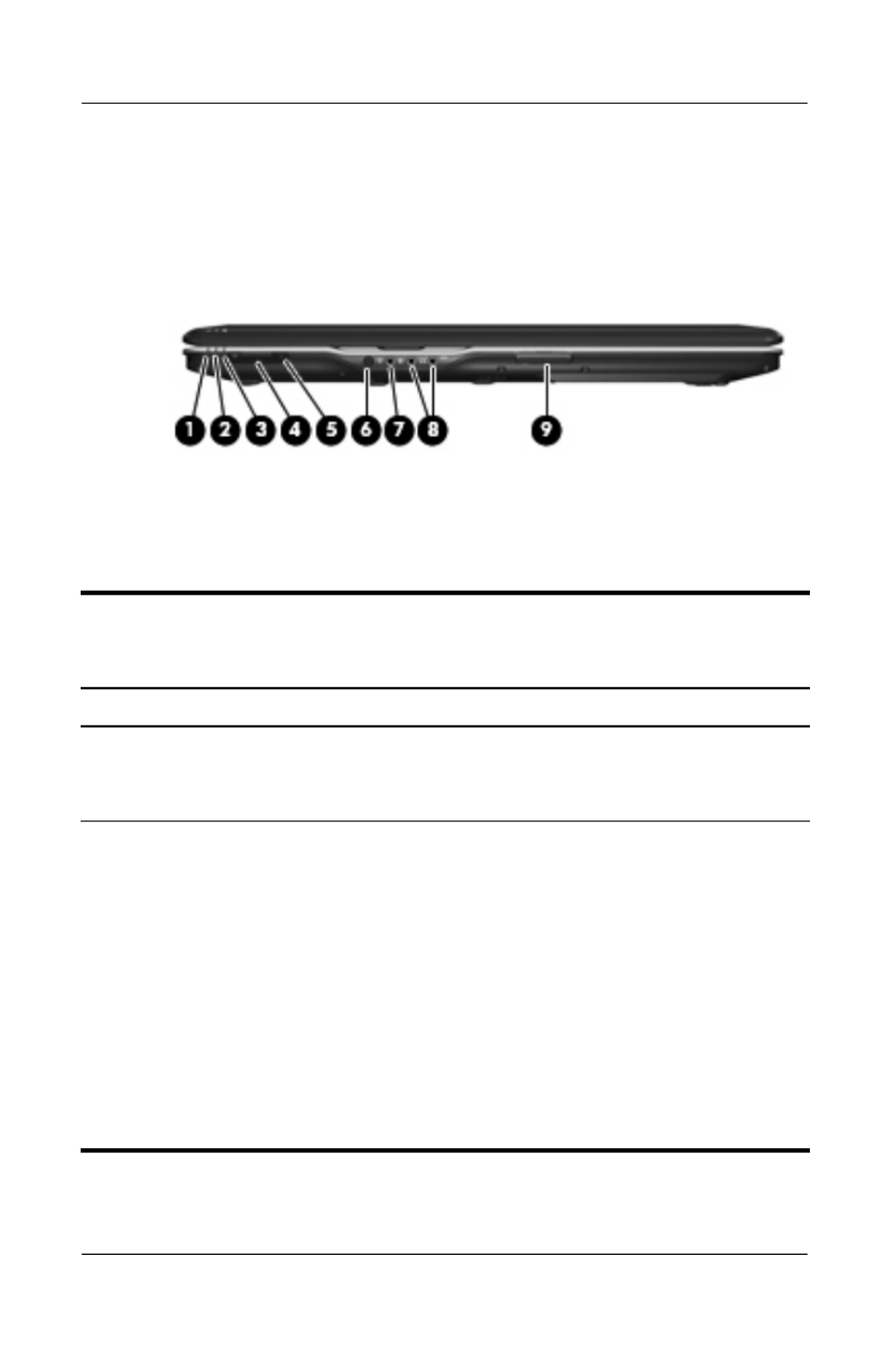
1.4 External Components
The external components on the front of the computer are shown
below and described in Table 1-1.
Front Components
Table 1-1
Front Components
Item Component Function
1 Power light On: The computer is on.
Blinking: The computer is in standby.
Off: The computer is off or in hibernation.
2 Battery light On: A battery is charging.
Blinking: A battery that is the only available
power source has reached a low-battery
condition. When the battery reaches a
critical low-battery condition, the battery
light begins blinking rapidly.
Off: If the computer is plugged into an
external power source, the light is turned off
when all batteries in the computer are fully
charged. If the computer is not plugged into
an external power source, the light stays off
until the battery reaches a low-battery
condition.

Product Description
Maintenance and Service Guide 1–7
3 Drive light Blinking: The hard drive or optical drive is
being accessed.
4 Wireless switch Turns the wireless feature on or off, but
does not create a wireless connection.
✎A wireless network must be set up in
order to establish a wireless
connection.
5 Wireless light Blue: An integrated wireless device, such
as a wireless local area network (LAN)
device and/or a Bluetooth® device, is
turned on.
Amber: All wireless devices are turned off.
6 Consumer infrared
lens (select models
only)
Receives a signal from the HP Remote
Control.
7 Audio-in
(microphone) jack
Connects an optional computer headset
microphone, stereo array microphone, or
monaural microphone.
8 Audio-out
(headphone) jack
Produces sound when connected to
optional powered stereo speakers,
headphones, ear buds, a headset, or
television audio.
Audio-out
(headphone) S/PDIF
jack
Provides enhanced audio performance,
including surround sound and other
high-end audio output.
9 Display lid latch Opens the computer.
Table 1-1
Front Components (Continued)
Item Component Function

1–8 Maintenance and Service Guide
Product Description
The external components on the left side of the computer are
shown below and described in Table 1-2.
Left-Side Components
Table 1-2
Left-Side Components
Item Component Function
1 Security cable slot Attaches an optional security cable to the
computer.
✎The security cable is designed to act
as a deterrent, but it may not prevent
the computer from being mishandled
or stolen.
2 S-Video-out jack Connects an optional S-Video device such
as a television, VCR, camcorder, overhead
projector, or video capture card.
3 External monitor port Connects an external VGA monitor or
projector.

Product Description
Maintenance and Service Guide 1–9
4 Expansion port 3 Connects the computer to an optional
expansion product.
✎The computer has only one
expansion port. The term expansion
port 3 describes the type of
expansion port.
5 RJ-45 (network) jack Connects a network cable.
✎The RJ-45 (network) jack provides
Gigabit Ethernet functionality.
6 RJ-11 (modem) jack Connects a modem cable.
7 HDMI port
(select models only)
Connects an optional audio or video device
such as a high-definition television, set-top
box, DVD player, or any compatible digital
or audio device.
8 USB ports (2) Connect optional USB devices.
9 1394 port Connects an optional IEEE 1394 or 1394a
device, such as a camcorder.
10 Digital Media Slot light On: A digital card is being accessed.
11 Digital Media Slot Supports the following optional digital card
formats: Secure Digital (SD) Memory Card,
MultiMediaCard (MMC), Secure Digital
Input/Output (SD I/O), Memory Stick (MS),
Memory Stick Pro (MSP), xDPicture Card
(XD), xD-Picture Card (XD) Type M.
Table 1-2
Left-Side Components (Continued)
Item Component Function

1–10 Maintenance and Service Guide
Product Description
The external components on the right side of the computer are
shown below and described in Table 1-3.
Right-Side Components

Product Description
Maintenance and Service Guide 1–11
Table 1-3
Right-Side Components
Item Component Function
1 USB ports (2) Connect optional USB devices.
2 ExpressCard slot Supports optional ExpressCard/54 cards.
3 Optical drive Reads an optical disc.
4 Power connector Connects an AC adapter.

1–12 Maintenance and Service Guide
Product Description
The computer keyboard components are shown below and
described in Table 1-4.
Keyboard Components

Product Description
Maintenance and Service Guide 1–13
Table 1-4
Keyboard Components
Item Component Function
1 Function keys Execute frequently used system functions
when pressed in combination with the
fn key.
2caps lock key Enables caps lock and turns on the caps
lock light.
3fn key Executes frequently used system
functions when pressed in combination
with a function key or the esc key.
4 Windows logo key Displays the Microsoft Windows Start
menu.
5 Windows
applications key
Displays a shortcut menu for items
beneath the pointer.
6 Arrow keys Move the cursor around the screen.
7 Numeric keypad keys Can be used like the keys on an external
numeric keypad.
8num lock key Enables numeric lock, turns on the
embedded numeric keypad, and turns
on the num lock light.

1–14 Maintenance and Service Guide
Product Description
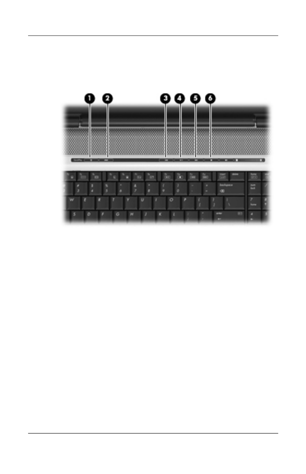
The computer top components are shown below and described in
Table 1-5.
Top Components, Part 1

Product Description
Maintenance and Service Guide 1–15
Table 1-5
Top Components, Part 1
Item Component Function
1 Integrated camera
(select models only)
Records video and captures still photos.
2 Internal microphones
(2, select models only)
Record sound.
✎A microphone icon next to each
microphone opening indicates that
the computer has internal
microphones.
3 Speakers (2) Produce sound.
4 Power button When the computer is
■Off, press to turn on the computer.
■On, press to enter hibernation.
■In standby, briefly press to exit standby.
■In hibernation, briefly press to
exit hibernation.
If the computer has stopped responding
and Microsoft® Windows® shutdown
procedures cannot be used, press and hold
the power button for at least 5 seconds to
turn off the computer.
5 Caps lock light On: Caps lock is on.
6 Volume mute button Mutes and restores speaker sound.
7 Volume scroll zone Adjusts speaker volume. Slide your finger
to the left to decrease volume and to the
right to increase volume. You can also tap
the minus sign on the scroll zone to
decrease volume, or tap the plus sign on
the scroll zone to increase volume.
8 Num lock light On: Num lock is on.
1–16 Maintenance and Service Guide
Product Description
The computer top components are shown below and described in
Table 1-6.
Top Components, Part 2

Product Description
Maintenance and Service Guide 1–17
Table 1-6
Top Components, Part 2
Item Component Function
1 Media button If QuickPlay is not installed and the
computer is
■On, opens the music program or Media
menu, which allows you to select a
multimedia program.
■Off, does not function.
■In standby, resumes from standby into
Windows.
If QuickPlay is installed and the computer is
■On, opens the music program or Media
menu, which allows you to select a
multimedia program.
■Off, opens the music program or the
Media menu, which allows you to select
a multimedia program.
■In standby, resumes from standby into
Windows.
✎The media button does not affect the
procedure for restoring from
hibernation.
2 DVD button When the computer is
✎On, opens the default DVD program
to start a DVD in the optical drive.
✎Off, opens QuickPlay to start a DVD
in the optical drive. If the QuickPlay
software is not installed, the DVD
button starts in Windows.
✎In hibernation, opens QuickPlay to
start a DVD in the optical drive. If
QuickPlay is not installed, the
computer resumes from hibernation.

1–18 Maintenance and Service Guide
Product Description
3 Previous/rewind
button
When a disc is playing in the optical drive:
■Plays the previous track or chapter,
when pressed once.
■Rewinds when pressed with the fn key.
4 Play/pause button When a disc is in the optical drive and is
■Not playing, plays the disc.
■Playing, pauses the disc.
5 Next/fast forward
button
When a disc is playing in the optical drive:
■Play the next track or chapter, when
pressed once.
■Fast forwards when pressed with the
fn key.
6 Stop button When a disc is playing in the optical drive,
stops the current disc activity.
Table 1-6
Top Components, Part 2 (Continued)
Item Component Function
Product Description
Maintenance and Service Guide 1–19
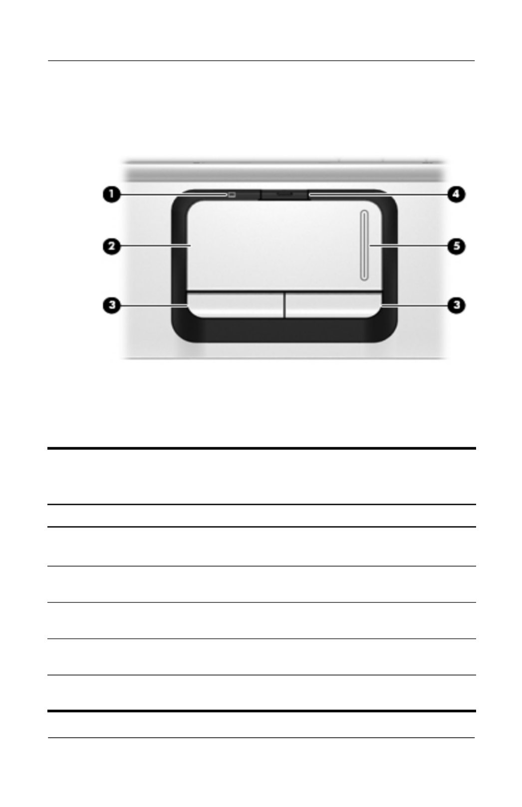
The computer TouchPad components are shown below and
described in Table 1-7.
TouchPad Components
Table 1-7
Touchpad Components
Item Component Function
1 TouchPad light Blue: TouchPad is enabled.
Amber: TouchPad is disabled.
2 TouchPad Moves the pointer and selects or activates
items on the screen.
3 Left and right
TouchPad buttons
Function like the left and right buttons on an
external mouse.
4 TouchPad on/off
button
Enables/disables the TouchPad.
5 TouchPad vertical
scroll zone
Allows you to scroll up or down.

1–20 Maintenance and Service Guide
Product Description
The external components on the bottom of the computer are
shown below and described in Table 1-8.
Bottom Components
Table 1-8
Bottom Components
Item Component Function
1 Battery bay Holds the battery.
2 Battery release latch Releases the battery from the
battery bay.

Product Description
Maintenance and Service Guide 1–21
3 Optical drive Reads an optical disc.
4 Secondary hard drive bay Holds an optional secondary hard drive.
Primary hard drive bay Hold the primary hard drive.
5 Vents (6) Enable airflow to cool internal
components.
✎The computer fan starts up
automatically to cool internal
components and prevent
overheating. It is normal for the
internal fan to cycle on and off
during routine operation.
6 Memory module
compartment
Contains the memory module slots, the
Mini Card slot, and the RTC battery.
Table 1-8
Bottom Components (Continued)
Item Component Function

1–22 Maintenance and Service Guide
Product Description
1.5 Design overview
This section presents a design overview of key parts and features
of the computer. Refer to Chapter 3, “Illustrated Parts Catalog,”
to identify replacement parts, and Chapter 5, “Removal and
Replacement Procedures,” for disassembly steps.
The system board provides the following device connections:
■AMD Mobile Turion and Mobile AMD Athlon processors
■Audio
■Display
■ExpressCard
■Fan
■Hard drive
■Intel Core Duo processors
■Keyboard and TouchPad
■Memory module
■Mini Card module
ÄCAUTION: To properly ventilate the computer, allow at least a 7.6-cm
(3-inch) clearance on the left and right sides of the computer.
The computer uses an electric fan for ventilation. The fan is
controlled by a temperature sensor and is designed to turn on
automatically when high temperature conditions exist. These
conditions are affected by high external temperatures, system
power consumption, power management/battery conservation
configurations, battery fast charging, and software. Exhaust air is
displaced through the ventilation grill located on the left side of
the computer.

Maintenance and Service Guide 2–1
2
Troubleshooting
ÅWARNING: Only authorized technicians trained by HP should repair
this equipment. All troubleshooting and repair procedures are detailed
to allow only subassembly-/module-level repair. Because of the
complexity of the individual boards and subassemblies, do not attempt
to make repairs at the component level or modifications to any printed
wiring board. Improper repairs can create a safety hazard. Any
indication of component replacement or printed wiring board
modification may void any warranty or exchange allowances.
2.1 Setup Utility in Windows XP
The Setup Utility is a ROM-based information and customization
utility that can be used even when your Windows operating
system is not working or will not load.
The utility reports information about the computer and provides
settings for startup, security, and other preferences.
1. Turn on or restart the computer in Windows.
2. Before Windows opens and while the “Press <F10> to enter
setup” prompt is displayed in the lower-left corner of the
screen, press f10.
Using the Setup Utility
Changing the Language of the Setup Utility
The following procedure explains how to change the language of
the Setup Utility. If the computer is not in the Setup Utility, begin
at step 1. If the computer is in the Setup Utility, begin at step 2.

2–2 Maintenance and Service Guide
Troubleshooting
1. To open the Setup Utility, turn on or restart the computer in
Windows, and then press f10 while the prompt, “Press <F10>
to enter setup,” is displayed in the lower-left corner of the
screen.
2. Use the arrow keys to select System Configuration >
Language, and then press enter.
3. Press f5 f6 or (or use the arrow keys) to select a language, and
then press enter to select a language.
4. When a confirmation prompt with your preference selected
is displayed, press enter to save your preference.
5. To set your preferences and exit the Setup Utility, press f10
and then follow the instructions on the screen.
Your preferences go into effect when the computer restarts in
Windows.
Navigating and Selecting in the Setup Utility
Because the Setup Utility is not Windows-based, it does not
support the TouchPad. Navigation and selection are by keystroke.
■To choose a menu or a menu item, use the arrow keys.
■To choose an item in a drop-down list or to toggle a field,
for example an Enable/Disable field, use either the arrow
keys or f5 or f6.
■To select an item, press enter.
■To close a text box or return to the menu display, press f1.
■To display additional navigation and selection information
while the Setup Utility is open, press f1.
Displaying System Information
The following procedure explains how to display system
information in the Setup Utility. If the Setup Utility is not open,
begin at step 1. If the Setup Utility is open, begin at step 2.

Troubleshooting
Maintenance and Service Guide 2–3
1. To start the Setup Utility, turn on or restart the computer in
Windows, and then press f10 while the prompt, “Press <F10>
to enter setup,” is displayed in the lower-left corner of the
screen.
2. Access the system information by using the Main menu.
3. To close the Setup Utility without changing any settings, use
the arrow keys to select Exit > Exit Discarding Changes,
and then press enter. (The computer restarts in Windows.)
Restoring Default Settings in the Setup Utility
The following procedure explains how to restore the Setup Utility
default settings. If the computer is not in the Setup Utility, begin
at step 1. If the computer is in the Setup Utility, begin at step 2.
1. To start the Setup Utility, turn on or restart the computer in
Windows, and then press f10 while the prompt, “Press <F10>
to enter setup,” is displayed in the lower-left corner of the
screen.
2. Select Exit > Load Setup Defaults, and then press f10.
3. When the Setup Confirmation is displayed, press enter to save
your preferences.
4. To set your preferences and exit the Setup Utility, press f10,
and then follow the instructions on the screen.
The Setup Utility default settings are set when you exit the
Setup Utility and go into effect when the computer restarts.
✎Your password, security, and language settings are not changed
when you restore the factory default settings.

2–4 Maintenance and Service Guide
Troubleshooting
Using Advanced Setup Utility Features
This guide describes the Setup Utility features recommended for
all users. For more information about the Setup Utility features
recommended for advanced users only, refer to the Help and
Support Center, which is accessible only when the computer is in
Windows.
The Setup Utility features available for advanced users include a
hard drive self-test, a Network Service Boot, and settings for boot
order preferences.
The “<F12> to boot from LAN” message that is displayed in the
lower-left corner of the screen each time the computer is started
or restarted in Windows or restored from hibernation is the
prompt for a Network Service Boot.
The “Press <ESC> to change boot order” message that is
displayed in the lower-left corner of the screen each time the
computer is started or restarted in Windows or restored from
hibernation is the prompt to change the boot order.
Closing the Setup Utility
You can close the Setup Utility with or without saving changes.
■To close the Setup Utility and save your changes from the
current session, use either of the following procedures:
❏Press f10, and then follow the instructions on the screen.
– or –
❏If the Setup Utility menus are not visible, press esc to
return to the menu display. Then use the arrow keys to
select Exit > Exit Saving Changes, and then press enter.
When you use the f10 procedure, you are offered an option
to return to the Setup Utility. When you use the Exit
Saving Changes procedure, the Setup Utility closes when
you press enter.

Troubleshooting
Maintenance and Service Guide 2–5
■To close the Setup Utility without saving your changes from
the current session:
If the Setup Utility menus are not visible, press esc to return
to the menu display. Then use the arrow keys to select Exit >
Exit Discarding Changes, and then press enter.
After the Setup Utility closes, the computer restarts in Windows.
Setup Utility Menus
The menu tables in this section provide an overview of Setup
Utility options.
✎Some of the Setup Utility menu listed in this chapter may not
be supported by your computer.
Main Menu
Table 2-1
Main Menu
Select To Do This
System Information ■View and change the system time and date.
■View identification information about the
computer.
■View specification information about the
processor, memory size, system BIOS, and
keyboard controller version (select models
only).

2–6 Maintenance and Service Guide
Troubleshooting
Security Menu
System Configuration Menu
Table 2-2
Security Menu
Select To Do This
Administrator password Enter, change, or delete an administrator
password.
Power-on password Enter, change, or delete a power-on password.
Table 2-3
System Configuration Menu
Select To Do This
Language Support Change the Setup Utility language.
Embedded WLAN Device
Radio
Enable/disable an embedded wireless LAN
device.
Embedded Bluetooth
Device (select models only)
Enable/disable an embedded Bluetooth device
(select models only).
Enhanced SATA support
(select models only)
Enable/disable enhanced SATA mode.

Troubleshooting
Maintenance and Service Guide 2–7
Diagnostics Menu
Boot Options Set the following boot options:
■f10 and f12 Delay (sec.)—Set the delay for the
f10 and f12 functions of the Setup Utility in
intervals of 5 seconds each (0, 5, 10, 15, 20).
■CD-ROM boot—Enable/disable boot from
CD-ROM.
■Floppy boot—Enable/disable boot from Floppy.
■Internal Network Adapter boot—Enable/disable
boot from Internal Network Adapter.
■Boot Order—Set the boot order for:
❐USB Floppy
❐ATAPI CD/DVD ROM Drive
❐Hard drive
❐USB Diskette on Key
❐USB Hard drive
❐Network adapter
Table 2-4
Diagnostics Menu
Select To Do This
Hard Disk Self Test Run a comprehensive self-test on the hard drive.
Table 2-3
System Configuration Menu (Continued)
Select To Do This

2–8 Maintenance and Service Guide
Troubleshooting
2.2 Setup Utility in Windows Vista
The Setup Utility is a ROM-based information and customization
utility that can be used even when your Windows® operating
system is not working or will not load.
✎The fingerprint reader (select models only) does not work
when accessing the Setup Utility.
The utility reports information about the computer and provides
settings for startup, security, and other preferences.
To start the Setup Utility:
1. Turn on or restart the computer.
2. Before Windows opens and while “Press <F10> to enter
setup” is displayed in the lower-left corner of the screen,
press f10.
Using the Setup Utility
Changing the Language of the Setup Utility
The following procedure explains how to change the language of
the Setup Utility. If the Setup Utility is not already running, begin
at step 1. If the Setup Utility is already running, begin at step 2.
1. To start the Setup Utility, turn on or restart the computer, and
then press f10 while “Press <F10> to enter setup” is displayed
in the lower-left corner of the screen.
2. Use the arrow keys to select System Configuration >
Language, and then press enter.
3. Press f5 f6 or (or use the arrow keys) to select a language, and
then press enter to select a language.
4. When a confirmation prompt with your preference selected
is displayed, press enter to save your preference.

Troubleshooting
Maintenance and Service Guide 2–9
5. To set your preferences and exit the Setup Utility, press f10
and then follow the instructions on the screen.
Your preferences go into effect when the computer restarts in
Windows.
Navigating and Selecting in the Setup Utility
Because the Setup Utility is not Windows-based, it does not
support the TouchPad. Navigation and selection are by keystroke.
■To choose a menu or a menu item, use the arrow keys.
■To choose an item in a drop-down list or to toggle a field,
for example an Enable/Disable field, use either the arrow
keys or f5 or f6.
■To select an item, press enter.
■To close a text box or return to the menu display, press esc.
■To display additional navigation and selection information
while the Setup Utility is open, press f1.
Displaying System Information
The following procedure explains how to display system
information in the Setup Utility. If the Setup Utility is not open,
begin at step 1. If the Setup Utility is open, begin at step 2.
1. To start the Setup Utility, turn on or restart the computer, and
then press f10 while “Press <F10> to enter setup” is displayed
in the lower-left corner of the screen.
2. Access the system information by using the Main menu.
3. To exit the Setup Utility without changing any settings, use
the arrow keys to select Exit > Exit Discarding Changes,
and then press enter. (The computer restarts in Windows.)

2–10 Maintenance and Service Guide
Troubleshooting
Restoring Default Settings in the Setup Utility
The following procedure explains how to restore the Setup Utility
default settings. If the Setup Utility is not already running, begin
at step 1. If the Setup Utility is already running, begin at step 2.
1. To start the Setup Utility, turn on or restart the computer, and
then press f10 while “Press <F10> to enter setup” is displayed
in the lower-left corner of the screen.
2. Select Exit > Load Setup Defaults, and then press enter.
3. When the Setup Confirmation is displayed, press enter to save
your preferences.
4. To set your preferences and exit the Setup Utility, press f10,
and then follow the instructions on the screen.
The Setup Utility default settings are set when you exit the
Setup Utility and go into effect when the computer restarts.
✎Your password, security, and language settings are not changed
when you restore the factory default settings.
Using Advanced Setup Utility Features
This guide describes the Setup Utility features recommended for
all users. For more information about the Setup Utility features
recommended for advanced users only, refer to Help and Support,
which is accessible only when the computer is in Windows.
The Setup Utility features available for advanced users include a
hard drive self-test, a Network Service Boot, and settings for boot
order preferences.
The “<F12> to boot from LAN” message that is displayed in the
lower-left corner of the screen each time the computer is started
or restarted in Windows is the prompt for a Network Service
Boot.

Troubleshooting
Maintenance and Service Guide 2–11
The “Press <ESC> to change boot order” message that is
displayed in the lower-left corner of the screen each time the
computer is started or restarted in Windows is the prompt to
change the boot order.
Closing the Setup Utility
You can close the Setup Utility with or without saving changes.
■To close the Setup Utility and save your changes from the
current session, use either of the following procedures:
❏Press f10, and then follow the instructions on the screen.
– or –
❏If the Setup Utility menus are not visible, press esc to
return to the menu display. Then use the arrow keys to
select Exit > Exit Saving Changes, and then press enter.
When you use the f10 procedure, you are offered an option
to return to the Setup Utility. When you use the Exit
Saving Changes procedure, the Setup Utility closes when
you press enter.
■To close the Setup Utility without saving your changes from
the current session:
If the Setup Utility menus are not visible, press esc to return
to the menu display. Then use the arrow keys to select Exit >
Exit Discarding Changes, and then press enter.
After the Setup Utility closes, the computer restarts in Windows.
Setup Utility Menus
The menu tables in this section provide an overview of Setup
Utility options.
✎Some of the Setup Utility menu listed in this chapter may not
be supported by your computer.

2–12 Maintenance and Service Guide
Troubleshooting
Main Menu
Security Menu
System Configuration Menu
Table 2-1
Main Menu
Select To Do This
System Information ■View and change the system time and date.
■View identification information about the
computer.
■View specification information about the
processor, memory size, system BIOS, and
keyboard controller version (select models only).
Table 2-2
Security Menu
Select To Do This
Administrator password Enter, change, or delete an administrator
password.
Power-on password Enter, change, or delete a power-on password.
Table 2-3
System Configuration Menu
Select To Do This
Language Support Change the Setup Utility language.
Enhanced SATA support
(select models only)
Enable/disable enhanced SATA mode.

Troubleshooting
Maintenance and Service Guide 2–13
Boot Options Set the following boot options:
■f10 and f12 Delay (sec.)—Set the delay for the
f10 and f12 functions of the Setup Utility in
intervals of 5 seconds each (0, 5, 10, 15, 20).
■CD-ROM boot—Enable/disable boot from
CD-ROM.
■Floppy boot—Enable/disable boot from Floppy.
■Internal Network Adapter boot—Enable/disable
boot from Internal Network Adapter.
■Boot Order—Set the boot order for:
❐USB Floppy
❐ATAPI CD/DVD ROM Drive
❐Hard drive
❐USB Diskette on Key
❐USB Hard drive
❐Network adapter
Button Sound
(select models only)
Enable/disable the Quick Launch Button tapping
sound.
Video memory up to
(select models only)
Select the amount of video memory.
Table 2-3
System Configuration Menu
Select To Do This

2–14 Maintenance and Service Guide
Troubleshooting
Diagnostics Menu
Table 2-4
Diagnostics Menu
Select To Do This
Hard Disk Self Test Run a comprehensive self-test on the hard drive.
✎On models with two hard drives, this menu
option is called the Primary Hard Disk Self
Test.
Secondary Hard Disk Self
Test (select models only)
Run a comprehensive self-test on a secondary
hard drive.

Troubleshooting
Maintenance and Service Guide 2–15
2.3 Troubleshooting Flowcharts
Table 2-5
Troubleshooting Flowcharts Overview
Flowchart Description
2.1 “Flowchart 2.1—Initial Troubleshooting”
2.2 “Flowchart 2.2—No Power, Part 1”
2.3 “Flowchart 2.3—No Power, Part 2”
2.4 “Flowchart 2.4—No Power, Part 3”
2.5 “Flowchart 2.5—No Power, Part 4”
2.6 “Flowchart 2.6—No Video, Part 1”
2.7 “Flowchart 2.7—No Video, Part 2”
2.8 “Flowchart 2.8—Nonfunctioning Docking Device (if applicable)”
2.9 “Flowchart 2.9—No Operating System (OS) Loading”
2.10 “Flowchart 2.10—No OS Loading, Hard Drive, Part 1”
2.11 “Flowchart 2.11—No OS Loading, Hard Drive, Part 2”
2.12 “Flowchart 2.12—No OS Loading, Hard Drive, Part 3”
2.13 “Flowchart 2.13—No OS Loading, Diskette Drive”

2–16 Maintenance and Service Guide
Troubleshooting
Flowchart Description
2.14 “Flowchart 2.14—No OS Loading, Optical Drive”
2.15 “Flowchart 2.15—No Audio, Part 1”
2.16 “Flowchart 2.16—No Audio, Part 2”
2.17 “Flowchart 2.17—Nonfunctioning Device”
2.18 “Flowchart 2.18—Nonfunctioning Keyboard”
2.19 “Flowchart 2.19—Nonfunctioning Pointing Device”
2.20 “Flowchart 2.20—No Network/Modem Connection”
Table 2-5
Troubleshooting Flowcharts Overview (Continued)

Troubleshooting
Maintenance and Service Guide 2–17
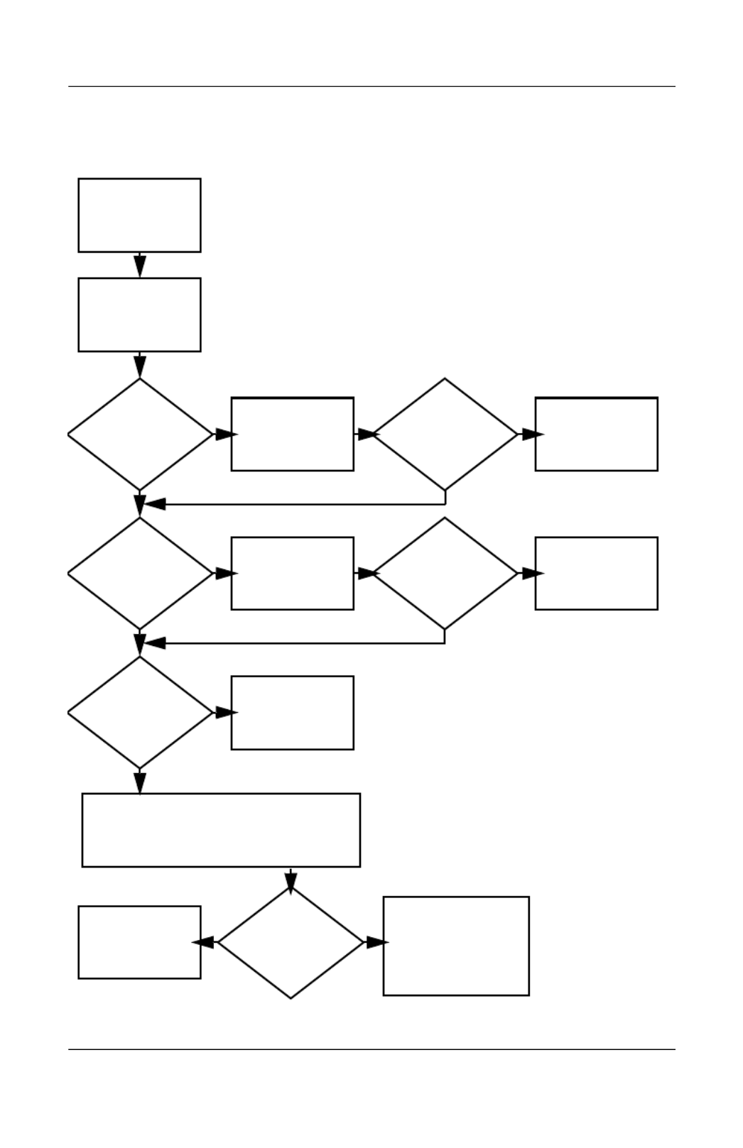
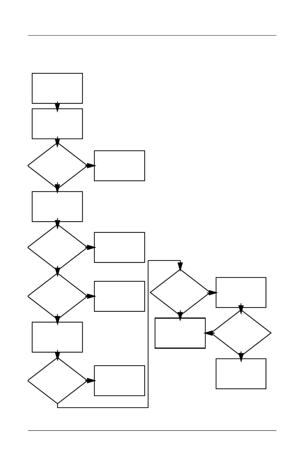
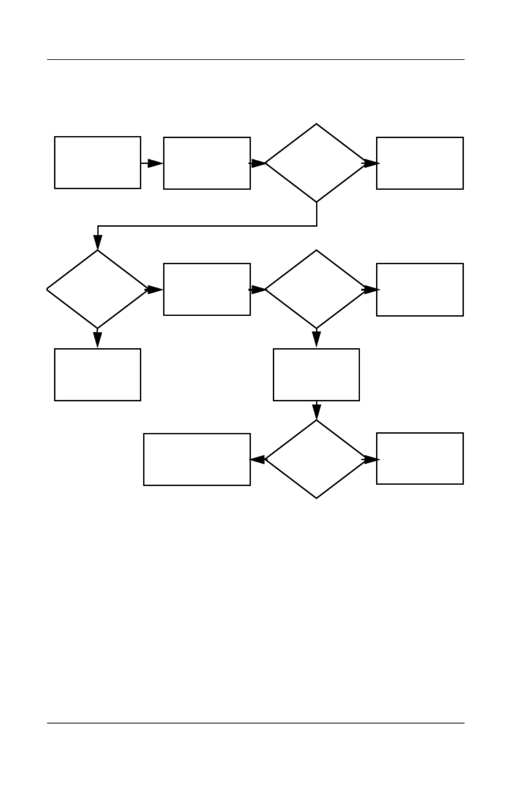
Flowchart 2.1—Initial Troubleshooting
Connecting
to network
or modem?
Begin
troubleshooting.
Is there
power?
Is the OS
loading?
Is there video?
(no boot)
Is there
sound?
Beeps,
LEDs, or error
messages?
Keyboard/
pointing
device
working?
Go to
“Flowchart
2.17—Nonfunc-
tioning Device.”
Go to
“Flowchart
2.2—No Power,
Part 1.”
Go to
“Flowchart
2.6—No Video,
Part 1.”
All drives
working?
Y
Y
Y
Y
Y
Y
Y
Y
N
N
N
N
N
End
N
N
N
Go to
“Flowchart
2.9—No Operating
System (OS)
Loading.”
Go to
“Flowchart
2.15—No Audio,
Part 1.”
Go to
“Flowchart
2.18—Nonfunc-
tioning Keyboard”
or “Flowchart
2.19—Nonfunc-
tioning Pointing
Device.”
Check
LED board,
speaker
connections.
Go to
“Flowchart
2.20—No
Network/Modem
Connection.”
2–18 Maintenance and Service Guide
Troubleshooting
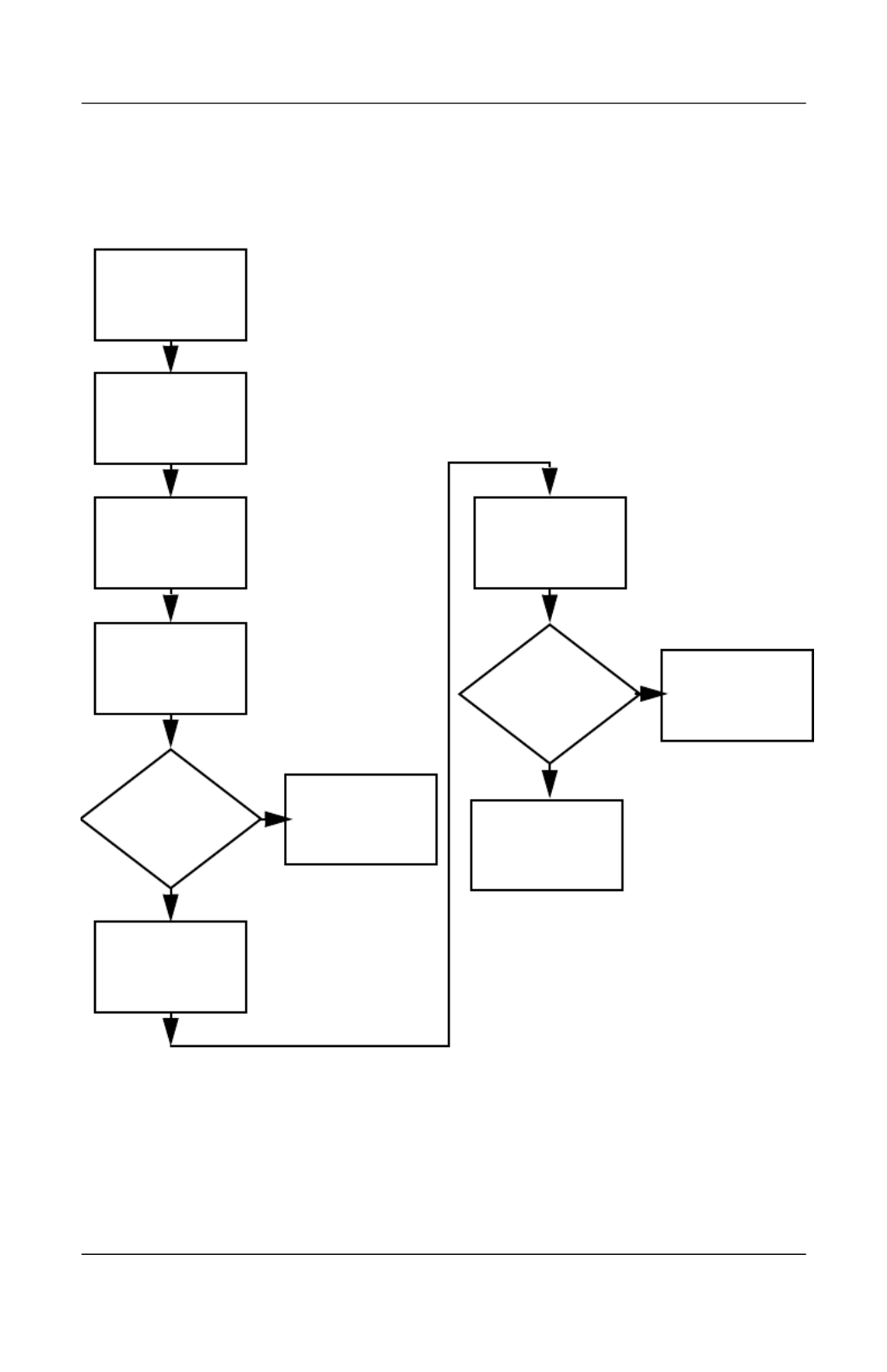
Flowchart 2.2—No Power, Part 1
1. Reseat the power cables in the docking
device and at the AC outlet.
2. Ensure the AC power source is active.
3. Ensure that the power strip is working.
Done
Remove from
docking device
(if applicable).
Power up
on battery
power?
Power up
on AC
power?
Power up in
docking
device?
Power up
on battery
power?
Power up
in docking
device?
Done
Reset
power.*
Reset
power.*
Power up
on AC power?
N
Y
Y
N
N
Y
N
N
Y
Y
Y N
1. On select models, there is a separate
reset button.
2. On select models, the computer can be
reset using the standby switch and either
the lid switch or the main power switch.
*NOTES
Go to
“Flowchart
2.4—No Power,
Part 3.”
Go to
“Flowchart
2.3—No Power,
Part 2.”
Go to
“Flowchart
2.8—Nonfunctioning
Docking Device (if
applicable).”
No power
(power LED
is off).

Troubleshooting
Maintenance and Service Guide 2–19
Flowchart 2.3—No Power, Part 2
Continued from
“Flowchart
2.2—No Power,
Part 1.”
Visually check for
debris in battery
socket and clean
if necessary.
Done
N
Y
Power on?
Check battery by
recharging it,
moving it to
another computer,
or replacing it.
Power on?
Done
Y
Replace
power supply
(if applicable).
N
Power on?
Done
Y
N
Go to
“Flowchart
2.4—No Power,
Part 3.”
2–20 Maintenance and Service Guide
Troubleshooting
Flowchart 2.4—No Power, Part 3
Continued from
“Flowchart
2.3—No Power,
Part 2.”
Reseat AC adapter
in computer and
at power source.
Internal or
external AC
adapter?
Done
Done
Done
Done
Power on?
Power on?
Power on?
Plug directly
into AC outlet.
Power LED
on?
Power outlet
active?
Try different
outlet.
Replace external
AC adapter.
Replace
power cord.
Y
N
Y
Y
Y
Y
N
N
N
N
External
Internal
Go to
“Flowchart
2.5—No Power,
Part 4.”

Troubleshooting
Maintenance and Service Guide 2–21
Flowchart 2.5—No Power, Part 4
Y
N
Continued from
“Flowchart
2.4—No Power,
Part 3.”
Reseat loose
components and
boards and
replace damaged
items.
Open
computer.
Loose or
damaged
parts?
Y
Close
computer and
retest.
Power on?
Done
N
Replace the following items (if applicable). Check
computer operation after each replacement:
1. Internal DC-DC converter*
2. Internal AC adapter
3. Processor board*
4. System board*
*NOTE: Replace these items as a set to prevent
shorting out among components.

2–22 Maintenance and Service Guide
Troubleshooting
Flowchart 2.6—No Video, Part 1
A
N
Stand-alone
or docking
device?
No video.
Replace the following one at a time. Test after each replacement.
1. Cable between computer and computer display (if applicable)
2. Display
3. System board
Internal or
external
display*?
Adjust
brightness. Video OK? Done
Docking Device
Internal
Stand-alone
External
Adjust
brightness.
Video OK? Done
Y
Press lid
switch to ensure
operation.
Video OK? Done
Y
N
Video OK?
Done Done
N
Check for bent
pins on cable.
Try
another
display.
Internal and
external
video OK?
Replace
system
board.
Y Y
N
N
*NOTE: To change from internal to
external display, use the hotkey
combination.
Y
Go to
“Flowchart
2.7—No Video,
Part 2.”

Troubleshooting
Maintenance and Service Guide 2–23
Flowchart 2.7—No Video, Part 2
Y
N
Continued from
“Flowchart
2.6—No Video,
Part 1.”
Done
Adjust external
monitor display.
Video OK?
Adjust
display
brightness.
Video OK?
Video OK?
Done
Done
Check that computer is properly
seated in docking device,
for bent pins on cable,
and for monitor connection.
Go to “A” in
“Flowchart
2.6—No Video,
Part 1.”
Check brightness
of external
monitor.
Try another
external
monitor.
Internal
and external
video OK?
Go to
“Flowchart
2.8—Nonfunctioning
Docking Device (if
applicable).”
Y
Y
Y
N
N
N
Remove
computer from
docking device,
if connected.
2–24 Maintenance and Service Guide
Troubleshooting
Flowchart 2.8—Nonfunctioning Docking Device
(if applicable)
Y
N
Reseat power
cord in docking
device and
power outlet.
N
Check voltage
setting on docking
device.
Reset monitor
cable connector at
docking device.
Reinstall
computer into
docking device.
Docking
device
operating?
Docking
device
operating? Done
Done
Y
Nonfunctioning
docking device.
Remove computer,
replace docking
device.
Test replacement
docking device with
new computer.
Troubleshooting
Maintenance and Service Guide 2–25
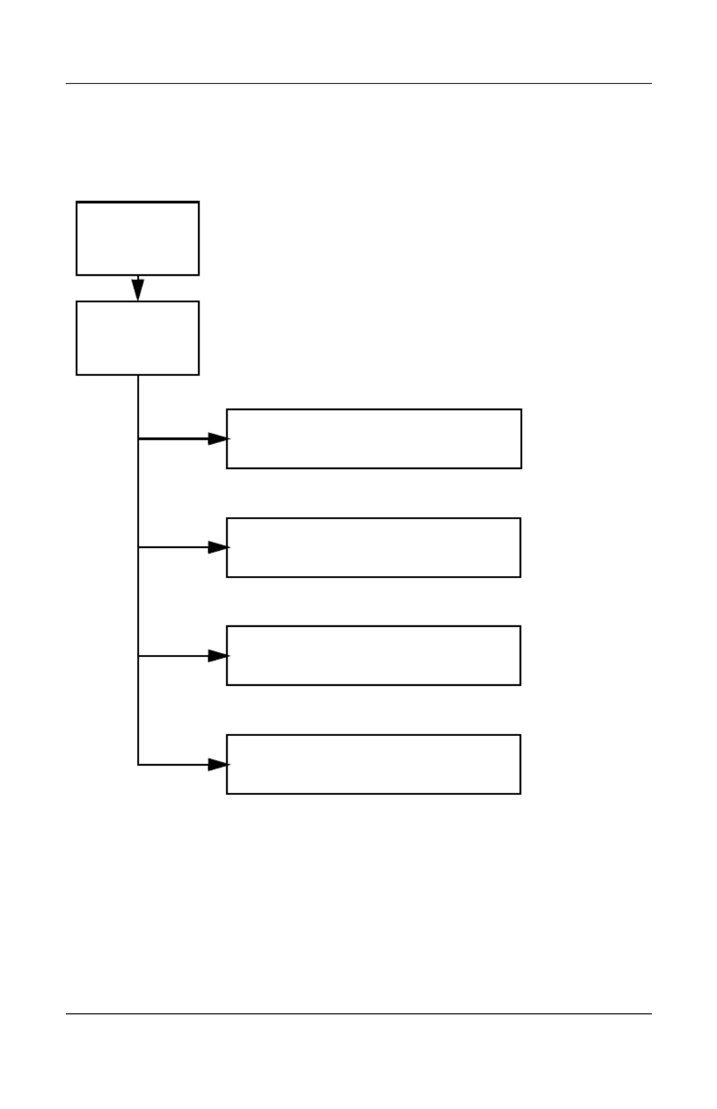
Flowchart 2.9—No Operating System (OS)
Loading
No OS loading from hard drive,
go to “Flowchart 2.10—No OS Loading,
Hard Drive, Part 1.”
Reseat power
cord in docking
device and
power outlet.
No OS
loading.*
*NOTE: Before beginning troubleshooting, always
check cable connections, cable ends, and drives
for bent or damaged pins.
No OS loading from diskette drive,
go to “Flowchart 2.13—No OS Loading,
Diskette Drive.”
No OS loading from optical drive,
go to “Flowchart 2.14—No OS Loading,
Optical Drive.”
No OS loading from network,
go to “Flowchart 2.20—No Network/Modem
Connection.”

2–26 Maintenance and Service Guide
Troubleshooting
Flowchart 2.10—No OS Loading, Hard Drive,
Part 1
Go to
“Flowchart
2.17—Nonfunctioning
Device.”
Y
Done
N
OS not
loading from
hard drive.
Nonsystem
disk message?
Go to
“Flowchart
2.11—No OS
Loading,
Hard Drive, Part 2.”
Reseat
external
hard drive.
OS loading? Done
Boot
from
CD?
Go to
“Flowchart
2.13—No OS
Loading,
Diskette Drive.”
Boot
from
hard drive?
Boot
from
diskette?
Change boot
priority through
the Setup Utility
and reboot.
Boot
from
hard drive?
Y
Y
Y
Y
Y
N
N
N
N
N
Check the Setup
utility for correct
booting order.

Troubleshooting
Maintenance and Service Guide 2–27
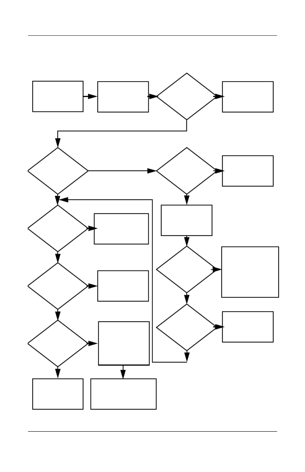
Flowchart 2.11—No OS Loading, Hard Drive,
Part 2
Load OS using
Operating System disc
(if applicable).
Continued from
“Flowchart
2.10—No OS
Loading,
Hard Drive, Part 1.”
Reseat
hard drive.
Done
Disc or
diskette in
drive?
1. Replace
hard drive.
2. Replace system
board.
Go to
“Flowchart
2.13—No OS
Loading,
Diskette Drive.”
Format hard drive
and bring to
a bootable
C:\ prompt.
Create partition,
and then format
hard drive to
bootable
C:\ prompt.
Boot
from diskette
drive?
Remove disc or
diskette and
reboot.
Y
N
Boot
from
hard drive?
Y
N
Y
N
Hard drive
accessible?
Y
N
Hard drive
accessible? Done
Run FDISK.
Y
N
Hard drive
partitioned?
Hard drive
formatted?
Y
N
Y
N
Computer
booted?
Done
Y
N
Go to
“Flowchart
2.12—No OS
Loading,
Hard Drive, Part 3.”
Go to
“Flowchart
2.12—No OS
Loading,
Hard Drive, Part 3.”

2–28 Maintenance and Service Guide
Troubleshooting
Flowchart 2.12—No OS Loading, Hard Drive,
Part 3
Y
System
files on hard
drive?
Continued from
“Flowchart
2.11—No OS
Loading,
Hard Drive, Part 2.”
Clean virus. Done
N
Install OS
and reboot.
Virus
on
hard drive?
OS
loading from
hard drive?
Y
N
Y
N
Y
N
Diagnostics on
disc or diskette?
Replace
hard drive.
Run diagnostics
and follow
recommendations.
Run SCANDISK and
check for
bad sectors.
Can bad
sectors
be fixed?
Replace
hard drive.
Y
N
Y
N
Fix bad
sectors.
Boot from
hard drive? Replace
hard drive.
Done
Troubleshooting
Maintenance and Service Guide 2–29
Flowchart 2.13—No OS Loading, Diskette Drive
Replace the following
components
individually, retesting
after each
replacement:
■Diskette drive
■System board
Done
Y
N
Reseat
diskette drive.
OS not loading
from
diskette drive.
Done
Y
Y
Y
Y
YY
Y
N
N
N
N
N
N
N
OS
loading?
Nonsystem
disk message?
Bootable
diskette
in drive?
Install bootable
diskette and
reboot computer.
Check diskette
for system files.
Try different
diskette.
Nonsystem
disk error?
OS
loading?
Boot
from another
device?
Enable drive
and cold boot
computer.
Is diskette
drive boot
order
correct?
Change boot
priority using
the Setup Utility.
Go to
“Flowchart
2.17—Nonfunc-
tioning Device.”
Diskette
drive enabled
in the Setup
utility?
Go to
“Flowchart
2.17—Nonfunctioning
Device.”
Reset the computer.
Refer to
Section 1.2,
“Resetting the
Computer,” for
instructions.

2–30 Maintenance and Service Guide
Troubleshooting
Flowchart 2.14—No OS Loading, Optical Drive
Y
Done
N
Bootable
disc in
drive?
Disc
in drive?
No OS
loading from
CD-ROM or
DVD-ROM drive.
Install bootable
disc and
reboot
computer.
Go to
“Flowchart
2.17—Nonfunctioning
Device.”
Go to
“Flowchart
2.17—Nonfunctioning
Device.”
Install
bootable disc.
Boots from
CD or DVD?
Boots from
CD or DVD?
Try another
bootable disc.
Booting
from another
device?
Booting
order
correct?
Correct boot
order using
the Setup Utility.
Done
Reseat
drive.
Y
Y
Y
Y
Y
N
N
N
N
N
Reset the computer.
Refer to
Section 1.2,
“Resetting the
Computer,” for
instructions.
Troubleshooting
Maintenance and Service Guide 2–31
Flowchart 2.15—No Audio, Part 1
No audio.
N
Computer in
docking device
(if applicable)?
Internal
audio?
Audio? Done
Undock
Audio? Done
Turn up audio
internally or
externally.
Go to
“Flowchart
2.16—No Audio,
Part 2.”
Go to
“Flowchart
2.17—Nonfunctioning
Device.”
Y
Y
Y
Y
N
N
N
Go to
“Flowchart
2.16—No Audio,
Part 2.”
Replace the
docking device.

2–32 Maintenance and Service Guide
Troubleshooting
Flowchart 2.16—No Audio, Part 2
Y N
Continued from
“Flowchart
2.15—No Audio,
Part 1.”
Reload
audio drivers.
Audio
driver in OS
configured?
Audio?
Y
Y
YN
N
N
Correct
drivers for
application?
Connect to
external
speaker.
Load drivers and
set configuration
in OS.
Audio? Done
Replace audio
board and
speaker
connections
in computer
(if applicable).
Replace the following components
individually, retesting after each
replacement:
■Internal speakers
■Audio board (if applicable)

Troubleshooting
Maintenance and Service Guide 2–33
Flowchart 2.17—Nonfunctioning Device
Done
Any physical
device detected?
Y
N
Unplug the nonfunctioning device from the computer
and inspect cables and plugs for bent or broken pins
or other damage.
Reseat
device.
Clear
CMOS.
Done
Fix or
replace
broken item.
Nonfunctioning
device.
Reattach device.
Close computer,
plug in power,
and reboot.
Device
boots
properly?
Go to
“Flowchart
2.9—No
Operating System
(OS) Loading.”
Device
boots
properly?
Replace hard drive.
Replace diskette
drive.
Replace NIC.
If integrated NIC,
replace system
board.
Y
N
Y
N

2–34 Maintenance and Service Guide
Troubleshooting
Flowchart 2.18—Nonfunctioning Keyboard
Y
N
Keyboard
operating
properly?
Keyboard
not operating
properly.
External
device
works?
Replace
system
board.
Replace
system
board.
Connect computer
to good external
keyboard.
Reseat internal
keyboard
connector
(if applicable).
Replace internal
keyboard or
cable.
Y
N
Y
N
Done Done
Keyboard
operating
properly?

Troubleshooting
Maintenance and Service Guide 2–35
Flowchart 2.19—Nonfunctioning Pointing Device
Y
N
Pointing device
not operating
properly.
External
device
works?
Replace
system
board.
Replace
system
board.
Connect computer
to good external
pointing device.
Reseat internal
pointing device
connector
(if applicable).
Replace internal
pointing device
or cable.
Y
N
Y
N
Done Done
Pointing device
operating
properly?
Pointing device
operating
properly?

2–36 Maintenance and Service Guide
Troubleshooting
Flowchart 2.20—No Network/Modem
Connection
Y
Disconnect all
power from
the computer
and open.
No network
or modem
connection.
N
Done
Digital
line?
Network
or modem jack
active?
Replace jack
or have jack
activated.
Connect
to nondigital
line.
NIC/modem
configured
in OS?
Reload
drivers and
reconfigure.
Reseat NIC/modem
(if applicable).
Replace
NIC/modem
(if applicable).
Replace
system
board.
Done
N
N
N
N
Y
Y
Y
Y
Network
or modem
connection
working?
Network
or modem
connection
working?
Maintenance and Service Guide 3–1
3
Illustrated Parts Catalog
This chapter provides an illustrated parts breakdown and a
reference for spare part numbers and option part numbers.
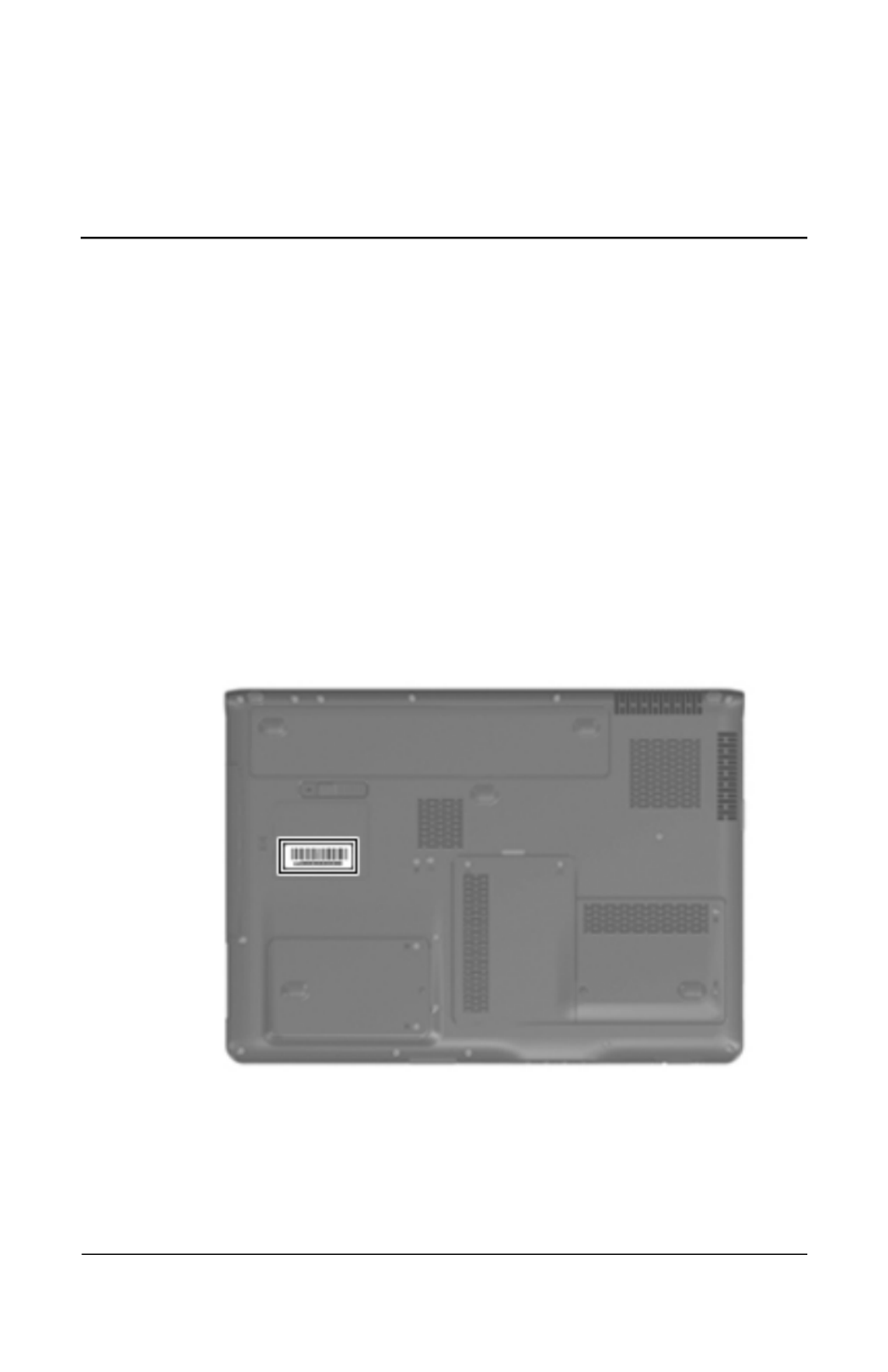
3.1 Serial Number Location
When ordering parts or requesting information, provide the
computer serial number and model number located on the bottom
of the computer.
3–2 Maintenance and Service Guide
Illustrated Parts Catalog
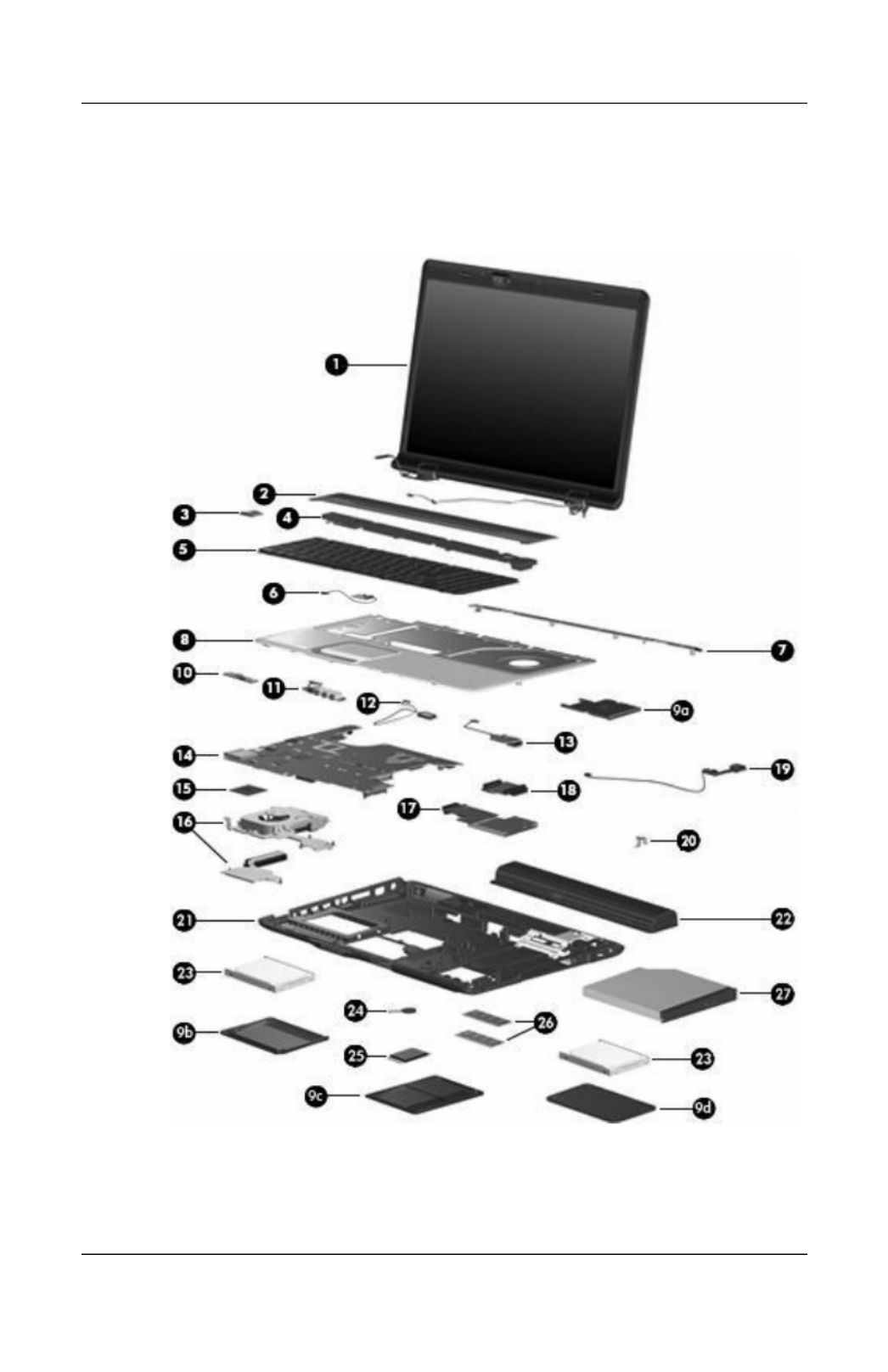
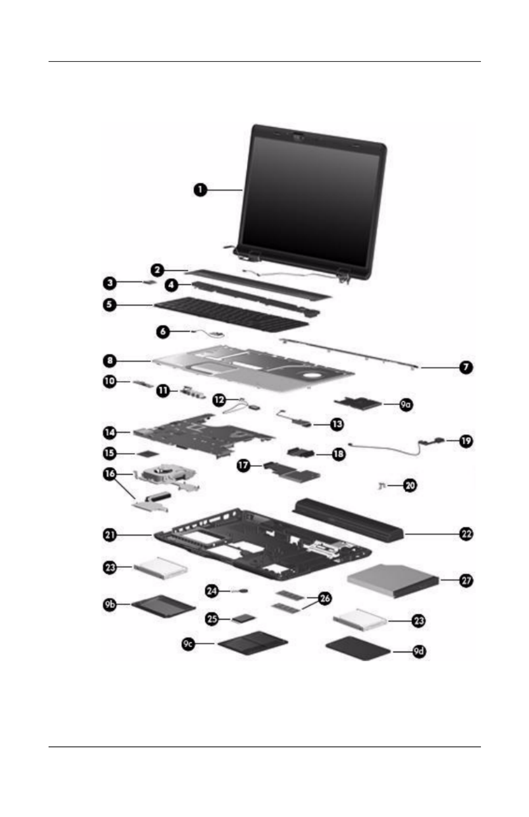
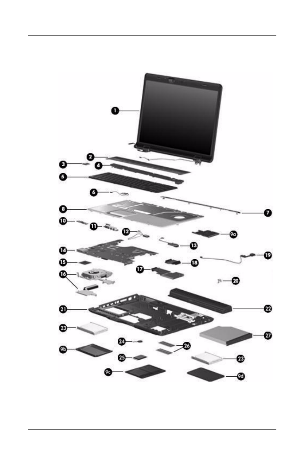
3.2 Computer Major Components
Computer Major Components

Illustrated Parts Catalog
Maintenance and Service Guide 3–3
Table 3-1
Spare Parts: Computer Major Components
Item Description
Spare Part
Number
1 Display assemblies (include wireless antenna transceivers
and cables)
For use with full-featured computer models (includes camera, camera
cable, and microphones):
17.0-inch, WXGA+, TFT Dual Lamp with BrightView
17.0-inch, SXGA+, TFT Single Lamp with BrightView
17.0-inch, WXGA+, TFT Single Lamp with BrightView
432948-001
432947-001
432946-001
For use with de-featured computer models (includes microphones):
17.0-inch, WXGA+, TFT Dual Lamp with BrightView
17.0-inch, SXGA+, TFT Single Lamp with BrightView
17.0-inch, WXGA+, TFT Single Lamp with BrightView
432951-001
432950-001
432949-001
✎Refer to Section 3.3, “Display Assembly Components,” for
display assembly internal component spare part number
information.
2 Switch cover (includes LED board and cable)
For model dv9200
For model dv9200 (EMEA only)
For model dv9000
438319-001
442920-001
432979-001
3 Power button board (includes power button
board cable)
432987-001
4 Speaker assembly 432994-001

3–4 Maintenance and Service Guide
Illustrated Parts Catalog
Computer Major Components

Illustrated Parts Catalog
Maintenance and Service Guide 3–5
Table 3-1
Spare Parts: Computer Major Components (Continued)
Item Description
Spare Part
Number
5Keyboards
For use in the following countries and regions:
Belgium
Denmark,
Finland,
Norway,
and Sweden
France
French Canada
Germany
Greece
Israel
Italy
Japan
441541-A41
441541-DH1
441541-051
441541-121
441541-041
441541-151
441541-BB1
441541-061
441541-291
Latin America
Netherlands
Portugal
Russia
Saudi Arabia
Spain
Switzerland
Thailand
Turkey
United Kingdom
United States
441541-161
441541-B31
441541-131
441541-251
441541-171
441541-071
441541-111
441541-281
441541-141
441541-031
441541-001
6Display lid switch module (includes display lid
switch module cable)
432993-001
7Top cover support trim 432978-001
8Top cover (includes TouchPad and TouchPad cable)
For model dv9200
For model dv9000
442919-001
432977-001
Plastics Kit 432981-001
9a
9b
9c
9d
ExpressCard slot bezel
Left hard drive cover (includes 2 captive screws, secured by C-clips)
Memory module compartment cover (includes 2 captive screws,
secured by C-clips)
Right hard drive cover (includes 2 captive screws, secured by
C-clips)

3–6 Maintenance and Service Guide
Illustrated Parts Catalog
Computer Major Components

Illustrated Parts Catalog
Maintenance and Service Guide 3–7
Table 3-1
Spare Parts: Computer Major Components (Continued)
Item Description
Spare Part
Number
10 Wireless switch board (includes wireless switch
board cable)
432991-001
11 Audio board (includes audio board cable and
infrared lens)
For model dv9200
For model dv9000
438369-001
432986-001
12 Bluetooth module (includes Bluetooth
module cable)
412766-002
13 USB/magnetic board (includes USB/magnetic
board cable)
For model dv9200
For model dv9000
438370-001
432990-001
14 System boards
For use only with computer models using Intel
processors:
G73 (includes 512 MB of video RAM)
G73M (includes 256 MB of video RAM)
G73 (includes 512 MB of video RAM) -
for Germany only
G73 (includes 256 MB of video RAM) -
for Germany only
434660-001
434659-001
441620-001
445178-001
For use only with computer models using AMD
processors
444002-001

3–8 Maintenance and Service Guide
Illustrated Parts Catalog
Computer Major Components

Illustrated Parts Catalog
Maintenance and Service Guide 3–9
Table 3-1
Spare Parts: Computer Major Components (Continued)
Item Description
Spare Part
Number
15 Processors (include thermal pad)
Intel Core Duo T7200 (2.00-GHz)
Intel Core Duo T5600 (1.83-GHz)
Intel Core Duo T5500 (1.66-GHz) - dv9200 models
Intel Core Duo T5300 (1.73-GHz) - dv9200 models
Intel Core Duo T5200 (1.66-GHz) - dv9200 models
Intel Core Duo T2250 (1.73-GHz) - dv9200 models
Intel Core Duo T2350 (1.86-GHz)
Intel Pentium Dual-Core T2080 (1.73-GHz)
434730-001
434731-011
436157-001
446814-001
436900-001
430897-001
441762-001
446812-001
AMD Turion TL-64 (2.2-GHz)
AMD Turion TL-60 (2.0-GHz)
AMD Turion TL-58 (1.9-GHz)
AMD Turion TL-56 (1.8-GHz)
AMD Athlon 64 TK-53 (1.7-GHz)
441535-001
436257-001
448561-001
431373-001
451013-001
Processor bracket 7.9 (not illustrated), for use with
the following processors: 434730-001 434731-001
436157-001 436900-001 446814-001
450370-001
Processor bracket 8.1 (not illustrated), for use with
the following processors: 430897-001, 446812-001,
441762-001
450371-001
16 Fan/heat sink assemblies
For use with models using Intel processors 434678-001
For use with models using AMD processors 438606-001
17 ExpressCard assembly 432988-001
18 Optical drive connector board 432992-001
19 USB board (includes USB board cable) 432989-001
20 Power connector bracket 432985-001
3–10 Maintenance and Service Guide
Illustrated Parts Catalog
Computer Major Components

Illustrated Parts Catalog
Maintenance and Service Guide 3–11
Table 3-1
Spare Parts: Computer Major Components (Continued)
Item Description
Spare Part
Number
21 Base enclosures (include wireless switch actuator
and power connector)
For use only with computer models using
Intel processors
436364-001
For use only with computer models using
AMD processors
438605-001
22 Batteries
8-cell, 4.4-Ahr for use only with computer models
using AMD processors
8-cell, 2.2-Ahr
432974-001
434674-001
23 Hard drives (include bracket and connector)
For use only with computer models using Intel
processors:
100-GB (5400-rpm)
100-GB (7200-rpm)
432997-001
434662-001
For use with all computer models:
200-GB (4200-rpm)
160-GB (5400-rpm)
120-GB (5400-rpm)
100-GB (7200-rpm)
80-GB (5400-rpm)
441424-001
438485-001
432998-001
441540-001
432996-001
For use with models using AMD processors:
120-MB (7200-rpm) 458116-001
Hard Drive Bracket Kit (includes the hard drive
bracket and screws; not illustrated)
434106-001
24 RTC battery (includes 2-sided tape) 431436-001

3–12 Maintenance and Service Guide
Illustrated Parts Catalog
Computer Major Components

Illustrated Parts Catalog
Maintenance and Service Guide 3–13
Table 3-1
Spare Parts: Computer Major Components (Continued)
Item Description
Spare Part
Number
25 Mini Card modules
802.11a/b/g WLAN Mini Card module for use in the
countries or regions listed below. These countries
and regions are categorized as most of the world1
(MOW1).
407674-001
Antigua &
Barbuda
Argentina
Australia
Bahamas
Barbados
Brunei
Canada
Chile
Dominican
Republic
Guam
Guatemala
Hong Kong
Panama
India
Indonesia
Malaysia
Mexico
New Zealand
Paraguay
Saudi Arabia
Tai wa n
The United
States
Vietnam
802.11a/b/g WLAN Mini Card module for use in the
countries or regions listed below. These countries
and regions are categorized as most of the world2
(MOW2).
407674-002
Aruba
Austria
Azerbaijan
Bahrain
Belgium
Bermuda
Bulgaria
Cayman
Islands
Columbia
Croatia
Cyprus
The Czech
Republic
Denmark
Egypt
El Salvador
Estonia
Finland
France
Georgia
Germany
Greece
Hungary
Iceland
Ireland
Italy
Latvia
Lebanon
The Philippines
Poland
Portugal
Romania
Russia
Serbia and
Montenegro
Singapore
Slovakia
Liechtenstein
Lithuania
Luxembourg
Malta
Monaco
The
Netherlands
Norway
Oman
Slovenia
South Africa
Spain
Sri Lanka
Sweden
Switzerland
Tur ke y
The United
Kingdom
Uzbekistan

3–14 Maintenance and Service Guide
Illustrated Parts Catalog
Computer Major Components

Illustrated Parts Catalog
Maintenance and Service Guide 3–15
Table 3-1
Spare Parts: Computer Major Components (Continued)
Item Description
Spare Part
Number
25 Mini Card modules (Continued)
802.11a/b/g WLAN Mini Card module for use in the
countries or regions listed below. These countries
and regions are categorized as most of the world2
(MOW2).
407674-002
Aruba
Austria
Azerbaijan
Bahrain
Belgium
Bermuda
Bulgaria
Cayman
Islands
Columbia
Croatia
Cyprus
Czech Republic
Denmark
Egypt
El Salvador
Estonia
Finland
France
Georgia
Germany
Greece
Hungary
Iceland
Ireland
Italy
Latvia
Lebanon
The Philippines
Poland
Portugal
Romania
Russia
Serbia and
Montenegro
Singapore
Slovakia
Liechtenstein
Lithuania
Luxembourg
Malta
Monaco
The
Netherlands
Norway
Oman
Slovenia
South Africa
Spain
Sri Lanka
Sweden
Switzerland
Tur ke y
The United
Kingdom
Uzbekistan
802.11a/b/g WLAN Mini Card module for use in the
countries or regions listed below. These countries
and regions are categorized as the rest of the world
(ROW).
407674-003
China
Ecuador
Haiti
Honduras
Pakistan
Peru
Qatar
South Korea
Uruguay
Venezuela
802.11b/g WLAN Mini Card module for use in Costa
Rica, Israel, Kuwait, Thailand, UAE, Ukraine
407674-004
802.11a/b/g WLAN Mini Card module for use only
in Japan
407674-291
3–16 Maintenance and Service Guide
Illustrated Parts Catalog
Computer Major Components

Illustrated Parts Catalog
Maintenance and Service Guide 3–17
Table 3-1
Spare Parts: Computer Major Components (Continued)
Item Description
Spare Part
Number
25 Mini Card modules (Continued)
For use only with models using AMD processors:
Broadcom 802.11b/g WLAN module for use in most
of the world
441090-001
Broadcom 802.11b/g WLAN module for use the rest
of the world
441090-002
Broadcom 4311AG 802.11a/b/g WLAN module for
use in most of the world
441075-001
Broadcom 4311AG 802.11a/b/g WLAN module for
use in the rest of the world
441075-002
802.11a/b/g EWC WLAN module for use in most of
the world
434661-001
802.11a/b/g EWC WLAN module for use in most of
the world
434661-002
26 Memory modules, PC-5300, 667-MHz, 1-DIMM
For use only with models using Intel processors:
1024-MB
512-MB
434742-001
434741-001
For use only with models using AMD processors:
2048-MB
1024-MB
512-MB
448003-001
432970-001
432969-001

3–18 Maintenance and Service Guide
Illustrated Parts Catalog
Computer Major Components

Illustrated Parts Catalog
Maintenance and Service Guide 3–19
Table 3-1
Spare Parts: Computer Major Components (Continued)
Item Description
Spare Part
Number
27 Optical drives (include bezel)
DVD±RW/R and CD-RW Double-Layer Combo
Drive with LightScribe
DVD±RW/R and CD-RW Double-Layer Combo
Drive
DVD/CD-RW Combo Drive
432973-001
432972-001
434673-001
Cable Kit (not illustrated), includes: 434677-001
Audio board cable
Bluetooth module cable
Display lid switch module cable
USB board cable
USB/magnetic board cable
Rubber Kit (not illustrated), includes: 432982-001
Rubber feet
2nd hard drive door
Rubber hinge
Display panel bumpers

3–20 Maintenance and Service Guide
Illustrated Parts Catalog
3.3 Display Assembly Components
Display Assembly Components
Table 3-2
Display Assembly Components
Spare Part Number Information
Item Description
Spare Part
Number
1 Display bezels
For use with Dual Lamp display panels with camera
For use with Dual Lamp display panels
without camera
For use with Single Lamp display panels with camera
For use with Single Lamp display panels
without camera
432956-001
436068-001
432955-001
436067-001

Illustrated Parts Catalog
Maintenance and Service Guide 3–21
2 Display Hinge Kit (includes left and right display hinges)
For use with Dual Lamp display panels
For use with Single Lamp display panels
432964-001
432963-001
3 Display inverters
For use with Dual Lamp display panels
For use with Single Lamp display panels
432959-001
431391-001
4 Camera module 432960-001
5 Display panels
17.0-inch, WXGA+, TFT Dual Lamp display panel
with BrightView
17.0-inch, SXGA+, TFT Single Lamp display panel
with BrightView
17.0-inch, WXGA+, TFT Single Lamp display panel
with BrightView
432954-001
432953-001
432952-001
6 Display hinge covers 432965-001
7 Wireless antenna transceivers and cables 432966-001
8 Microphones 432961-001
9 Display Cable Kit (includes camera cable) 432962-001
10 Display enclosures
For use with Dual Lamp display panels
For use with Single Lamp display panel
432958-001
432957-001
Display Screw Kit (includes screws and rubber screw
covers, not illustrated)
432967-001
Table 3-2
Display Assembly Components
Spare Part Number Information (Continued)
Item Description
Spare Part
Number
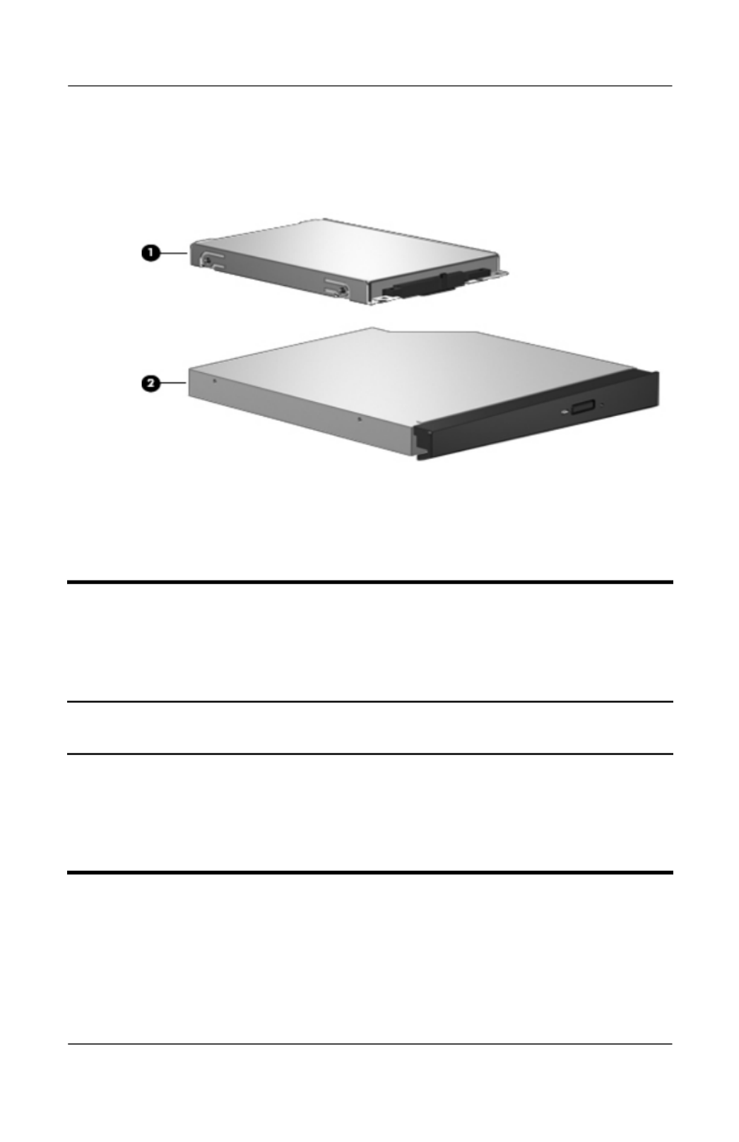
3–22 Maintenance and Service Guide
Illustrated Parts Catalog
3.4 Mass Storage Devices
Mass Storage Devices
Table 3-3
Mass Storage Devices
Spare Part Number Information
Item Description
Spare Part
Number
1 Hard drives (include bracket and connector)
For use only with computer models using Intel processors:
100-GB (7200-rpm)
100-GB (5400-rpm)
434662-001
432997-001

Illustrated Parts Catalog
Maintenance and Service Guide 3–23
For use with all computer models
200-GB (4200-rpm)
160-GB (5400-rpm)
120-GB (5400-rpm)
100-GB (7200-rpm)
80-GB (5400-rpm)
441424-001
438485-001
432998-001
441540-001
432996-001
For use with computer models using AMD processors:
120-MB (7200-rpm) 458116-001
1 Hard drives (Continued)
Hard drive Bracket Kit (not illustrated) 434106-001
Hard drive bracket rails (APD only) (not illustrated) 437385-001
Hard drive screws (APD only) (not illustrated) 437386-001
Hard drive connector (APD only) (not illustrated) 437387-001
2 Optical drives
DVD±RW/R and CD-RW Double-Layer Combo Drive
with LightScribe
DVD±RW/R and CD-RW Double-Layer Combo Drive
DVD/CD-RW Combo Drive
432973-001
432972-001
434673-001
Table 3-3
Mass Storage Devices
Spare Part Number Information (Continued)
Item Description
Spare Part
Number

3–24 Maintenance and Service Guide
Illustrated Parts Catalog
3.5 Plastics Kit
Plastics Kit Components

Illustrated Parts Catalog
Maintenance and Service Guide 3–25
Table 3-4
Plastics Kit
Spare Part Number Information
Item Description
Spare Part
Number
Plastics Kit 432981-001
1
2
3
4
Includes:
ExpressCard slot bezel
Memory module compartment cover (includes 2 captive screws,
secured by C-clips)
Right hard drive cover (includes 2 captive screws, secured by
C-clips)
Left hard drive cover (includes 2 captive screws, secured by C-clips)
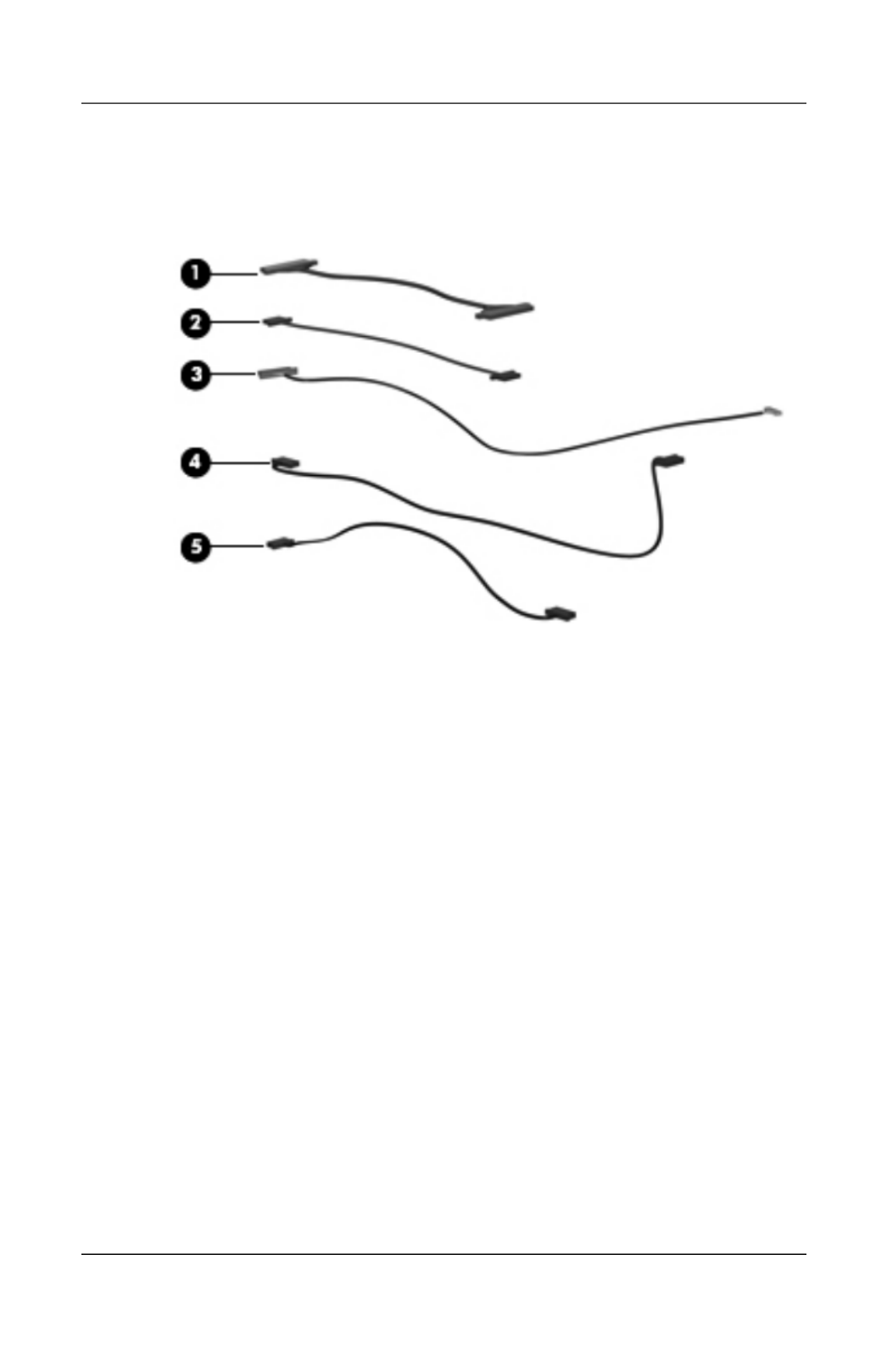
3–26 Maintenance and Service Guide
Illustrated Parts Catalog
3.6 Cable Kit
Cable Kit Components

Illustrated Parts Catalog
Maintenance and Service Guide 3–27
Table 3-5
Cable Kit
Spare Part Number Information
Item Description
Spare Part
Number
Cable Kit 434677-001
1
2
3
4
5
Includes:
Audio board cable
Display lid switch module cable
Bluetooth module cable
USB board cable
USB/magnetic board cable

3–28 Maintenance and Service Guide
Illustrated Parts Catalog
3.7 Miscellaneous
Table 3-6
Spare Parts: Miscellaneous
Description
Spare Part
Number
AC adapters
HP 90-W PFC AC adapter
HP 90-W non-PFC AC adapter
432309-001
432310-001
Composite S-Video and audio input cable 407939-001
Analog TV tuner 407941-001
Composite S-Video and audio input cable 407939-001
DVB-T TV tuner 412175-001
DVB-T TV tuner antenna 412176-001
DVB-T TV tuner antenna and antenna adapter 412176-002
Ear bud headset 371693-001
Backpack 405527-001
HP Remote Control 407313-001
Logo Kit 432984-001
RF input adapter cable 407940-001
USB digital drive 364727-001
USB travel mouse 435836-001
Optical wired mouse 436238-001
Remote control, ExpressCard (EMEA) 439254-001
Infrared emitter 439129-001
HP Remote Control 435743-001
Remote control, ExpressCard 439128-001

Illustrated Parts Catalog
Maintenance and Service Guide 3–29
TV tuner, ExpressCard 439130-001
TV tuner antenna 439131-001
Wireless laser mouse 430958-001
Express card kit, HD-DVD (with driver CD) 445170-001
Power cords for use with all computer models:
Belgium, Europe, Finland, France, Germany, Greece,
the Netherlands, Norway, Portugal, Spain, and Sweden
394279-021
Canada, French Canada, Latin America, Thailand, and
the United States
394279-001
Denmark 394279-081
Italy 394279-061
Japan 394279-291
People’s Republic of China 394279-AA1
United Kingdom and Hong Kong 394279-031
Power cords for use only with computer models using Intel processors:
Argentina 394279-D01
Australia and New Zealand 394279-011
India 394279-D61
Israel 394279-BB1
Switzerland 394279-111
Table 3-6
Spare Parts: Miscellaneous (Continued)
Description
Spare Part
Number

3–30 Maintenance and Service Guide
Illustrated Parts Catalog
Screw Kit (include the following screws; refer to Appendix
A, “Screw Listing,” for more information on screw
specifications and usage)
For use only with computer models using Intel processors 434676-001
For use only with computer models using AMD processors 432983-001
■ Phillips PM3.0×3.0 screw
■ Phillips PM2.5×11.0 screw
■ Phillips PM2.5×8.0 screw
■ Phillips PM2.5×7.0 screw
■ Phillips PM2.5×5.0 screw
■ Phillips PM2.5×4.0 screw
■ Phillips PM2.0×6.0 Screw
■ Phillips PM2.0×5.0 captive screw
■ Phillips PM2.0×4.0 screw
■ Phillips PM2.0×3.0 screw
Table 3-6
Spare Parts: Miscellaneous (Continued)
Description
Spare Part
Number

Illustrated Parts Catalog
Maintenance and Service Guide 3–31
3.8 Sequential Part Number Listing
Table 3-7
Spare Parts: Sequential Part Number Listing
Spare Part
Number Description
364727-001 USB digital drive
371693-001 Headset
394279-001 Power cord for use in Canada, French Canada, Latin America,
Thailand, and the United States
394279-011 Power cord for use in Australia and New Zealand
394279-021 Power cord for use in Belgium, Europe, Finland, France,
Germany, Greece, the Netherlands, Norway, Portugal, Spain,
and Sweden
394279-031 Power cord for use in the United Kingdom and Hong Kong
394279-061 Power cord for use in Italy
394279-081 Power cord for use in Denmark
394279-111 Power cord for use in Switzerland
394279-291 Power cord for use in Japan
394279-AA1 Power cord for use in The People’s Republic of China
394279-BB1 Power cord for use in Israel
394279-D01 Power cord for use in Argentina
394279-D61 Power cord for use in India
405527-001 HP Backpack
407313-001 HP Remote Control

3–32 Maintenance and Service Guide
Illustrated Parts Catalog
407674-001 802.11a/b/g WLAN Mini Card module for use in the MOW1
countries and regions listed below:
Antigua &
Barbuda
Argentina
Australia
Bahamas
Barbados
Brunei
Canada
Chile
Dominican
Republic
Guam
Guatemala
Hong Kong
Panama
India
Indonesia
Malaysia
Mexico
New Zealand
Paraguay
Saudi Arabia
Ta iwa n
The United States
Vietnam
407674-002 802.11a/b/g WLAN Mini Card module for use in the MOW2
countries and regions listed below:
Aruba
Austria
Azerbaijan
Bahrain
Belgium
Bermuda
Bulgaria
Cayman Islands
Columbia
Croatia
Cyprus
The Czech
Republic
Denmark
Egypt
El Salvador
Estonia
Finland
France
Georgia
Germany
Greece
Hungary
Iceland
Ireland
Italy
Latvia
Lebanon
The Philippines
Poland
Portugal
Romania
Russia
Serbia and
Montenegro
Singapore
Slovakia
Liechtenstein
Lithuania
Luxembourg
Malta
Monaco
The Netherlands
Norway
Oman
Slovenia
South Africa
Spain
Sri Lanka
Sweden
Switzerland
Tu rkey
The United
Kingdom
Uzbekistan
Table 3-7
Spare Parts: Sequential Part Number Listing (Continued)

3–34 Maintenance and Service Guide
Illustrated Parts Catalog
Spare Part
Number Description
432947-001 17.0-inch, SXGA+, TFT Single Lamp display assembly with
BrightView (includes camera, camera cable, microphones,
wireless antenna transceivers, and cables)
432948-001 17.0-inch, WXGA+, TFT Dual Lamp display assembly with
BrightView for use with full-featured computer models
(includes camera, camera cable, microphones, wireless
antenna transceivers, and cables)
432949-001 17.0-inch, WXGA+, TFT Single Lamp display assembly with
BrightView (includes microphones, wireless antenna
transceivers, and cables)
432950-001 17.0-inch, SXGA+, TFT Single Lamp display assembly with
BrightView (includes microphones, wireless antenna
transceivers, and cables)
432951-001 17.0-inch, WXGA+, TFT Dual Lamp display assembly with
BrightView for use with de-featured computer models
(includes microphones, wireless antenna transceivers,
and cables)
432952-001 17.0-inch, WXGA+, TFT Single Lamp display panel
with BrightView
432953-001 17.0-inch, SXGA+, TFT Single Lamp display panel
with BrightView
432954-001 17.0-inch, WXGA+, TFT Dual Lamp display panel
with BrightView
432955-001 Display bezel for use with Single Lamp display panels
with camera
432956-001 Display bezel for use with Dual Lamp display panels
with camera
432957-001 Display enclosure for use with Single Lamp display panel
432958-001 Display enclosure for use with Dual Lamp display panels
Table 3-7
Spare Parts: Sequential Part Number Listing (Continued)

Illustrated Parts Catalog
Maintenance and Service Guide 3–35
Spare Part
Number Description
432959-001 Display inverter for use with Dual Lamp display panels
432960-001 Camera module
432961-001 Microphones
432962-001 Display Cable Kit (includes camera cable)
432963-001 Display Hinge Kit for use with Single Lamp display panels
(includes left and right display hinges)
432964-001 Display Hinge Kit for use with Dual Lamp display panels
(includes left and right display hinges)
432965-001 Display hinge covers
432966-001 Wireless antenna transceivers and cables
432967-001 Display Screw Kit (includes screws and rubber screw covers)
432969-001 512-MB memory module, PC-5300, 667-MHz, 1-DIMM for use
only with models using AMD processors
432970-001 1024-MB memory module, PC-5300, 667-MHz, 1-DIMM for
use only with models using AMD processors
432972-001 DVD±RW/R and CD-RW Double-Layer Combo Drive
432973-001 DVD±RW/R and CD-RW Double-Layer Combo Drive
with LightScribe
432974-001 8-cell, 4.4-Ahr battery
432977-001 Top cover (includes TouchPad and TouchPad cable) for model
dv9000
432978-001 Top cover support trim
432979-001 Switch cover (includes LED board and cable) for model
dv9000
432981-001 Plastics Kit
Table 3-7
Spare Parts: Sequential Part Number Listing (Continued)

3–36 Maintenance and Service Guide
Illustrated Parts Catalog
432982-001 Rubber kit for models with AMD processors
432983-001 Escrow Kit for use only with computer models using AMD
processors
432984-001 Olga Kit
432985-001 Power connector bracket
432986-001 Audio board (includes audio board cable and infrared lens) for
model dv9000
432987-001 Power button board (includes power button board cable)
432988-001 ExpressCard assembly
432989-001 USB board (includes USB board cable)
432990-001 USB/magnetic board (includes USB/magnetic board cable) for
model dv9000
432991-001 Wireless switch board (includes wireless switch board cable)
432992-001 Optical drive connector board
432993-001 Display lid switch module (includes display lid switch
module cable)
432994-001 Speaker assembly
432996-001 80-GB, 5400-rpm hard drive (includes bracket and connector)
for use with all computer models
432997-001 100-GB, 5400-rpm hard drive (includes bracket and
connector) for use only with computer models with Intel
processors
432998-001 120-GB, 5400-rpm hard drive (includes bracket and
connector) for use with all computer models
434106-001 Hard Drive Bracket Kit
434659-001 G73M system board for use in models with Intel processors
(includes 256-MB of video RAM and thermal pad)
Table 3-7
Spare Parts: Sequential Part Number Listing (Continued)

Illustrated Parts Catalog
Maintenance and Service Guide 3–37
Spare Part
Number Description
434660-001 G73 system board for use in models with Intel processors
(includes 512-MB of video RAM and thermal pad)
434661-001 802.11a/b/g EWC WLAN module for use in most of the world
434661-002 802.11a/b/g EWC WLAN module for use in the rest of the
world
434662-001 100-GB, 7200-rpm hard drive (includes bracket and
connector) for use only with computer models using Intel
processors
434673-001 DVD/CD-RW Combo Drive
434674-001 8-cell, 2.2-Ahr battery
434676-001 Screw Kit for use only with computer models using Intel
processors
434677-001 Cable Kit
434678-001 Fan/heat sink assembly for use in computer models with Intel
processors (includes thermal pad)
434730-001 Intel Core Duo T7200 (2.0-GHz) processor (includes
thermal pad)
434731-001 Intel Core Duo T5600 (1.8-GHz) processor (includes
thermal pad)
434741-001 512-MB memory module, PC-5300, 667-MHz, 1-DIMM for use
only with models using Intel processors
434742-001 1024-MB memory module, PC-5300, 667-MHz, 1-DIMM for
use only with models using Intel processors
435743-001 HP Remote Control
435836-001 USB travel mouse
436067-001 Display bezel for use with Single Lamp display panels
without camera
Table 3-7
Spare Parts: Sequential Part Number Listing (Continued)

3–38 Maintenance and Service Guide
Illustrated Parts Catalog
436068-001 Display bezel for use with Dual Lamp display panels
without camera
436157-001 Intel Core Duo T5500 (1.66-GHz) processor (includes
thermal pad), for use with dv9200 models
436238-001 Optical wired mouse
436257-001 AMD Turion ML-60 2.0-GHz processor
436364-001 Base enclosure (includes wireless switch actuator and power
connector)
436900-001 Intel Core Duo T5200 (1.66-GHz) processor (includes
thermal pad), for use with dv9200 models
437385-001 Hard drive bracket rails (APD only)
437386-001 Hard drive screws (APD only)
437387-001 Hard drive connector (APD only)
438319-001 Switch cover (includes LED board and LED board cable) for
model dv9200
438369-001 Audio board (includes audio board cable and infrared lens) for
model dv9200
438370-001 USB/magnetic board (includes USB/magnetic board cable) for
model dv9200
438485-001 I160-GB (5400-rpm) hard drive for use with all computer
models
438605-001 Base enclosure for use only with computer models using AMD
processors (includes power connector)
438606-001 Fansink assembly for use only with computer models using
AMD processors
439128-001 Remote control, ExpressCard
439129-001 Infrared emitter
439130-001 TV tuner, ExpressCard
Table 3-7
Spare Parts: Sequential Part Number Listing (Continued)

Illustrated Parts Catalog
Maintenance and Service Guide 3–39
Spare Part
Number Description
439131-001 TV tuner antenna
439254-001 Remote control, ExpressCard (EMEA)
441075-001 Broadcom 4311AG 802.11a/b/g WLAN module for use in
most of the world
441090-001 Broadcom 802.11b/g WLAN module for use in most of the
world
441090-002 Broadcom 802.11b/g WLAN module for use in the rest of the
world
441424-001 200-GB (4200-rpm) hard drive
441540-001 100-GB (7200-rpm) hard drive
441541-001 Keyboard for use in the United States
441541-031 Keyboard for use in the United Kingdom
441541-041 Keyboard for use in Germany
441541-051 Keyboard for use in France
441541-061 Keyboard for use in Italy
441541-071 Keyboard for use in Spain
441541-111 Keyboard for use in Switzerland
441541-121 Keyboard for use in French Canada
441541-131 Keyboard for use in Portugal
441541-141 Keyboard for use in Turkey
441541-151 Keyboard for use in Greece
441541-161 Keyboard for use in Latin America
441075-002 Broadcom 4311AG 802.11a/b/g WLAN module for use in the
rest of the world
Table 3-7
Spare Parts: Sequential Part Number Listing (Continued)

3–40 Maintenance and Service Guide
Illustrated Parts Catalog
Spare Part
Number Description
441541-171 Keyboard for use in Saudi Arabia
441541-251 Keyboard for use in Russia
441541-281 Keyboard for use in Thailand
441541-291 Keyboard for use in Japan
441541-A41 Keyboard for use in Belgium
441541-B31 Keyboard for use in the Netherlands
441541-BB1 Keyboard for use in Israel
441541-DH1 Keyboard for use in Denmark, Finland, Norway, and Sweden
441620-001 G73 system board for use in models with Intel processors
(includes 512 MB of video RAM) for use in Germany only
441762-001 Intel Core Duo T2350 (1.86-GHz) processor (includes
thermal pad)
442919-001 Top cover (includes TouchPad and TouchPad cable) for
model dv9200
442920-001 Switch cover (includes LED board and LED board cable) for
model dv9200 for use in EMEA only
444002-001 System board for use in computer models with AMD
processors
445170-001 Express card kit, HD-DVD (with driver CD)
445178-001 G73 system board for use in models with Intel processors
(includes 256 MB of video RAM) for use in Germany only
446812-001 Intel Pentium Dual-Core (1.73-GHz) processor (includes
thermal pad)
446814-001 Intel Core Duo T5300 (1.73-GHz) - dv9200 models
processor (includes thermal pad)
Table 3-7
Spare Parts: Sequential Part Number Listing (Continued)

Maintenance and Service Guide 4–1
4
Removal and Replacement
Preliminaries
This chapter provides essential information for proper and
safe removal and replacement service.
4.1 Tools Required
You will need the following tools to complete the removal and
replacement procedures:
■Magnetic screwdriver
■Phillips P0 and P1 screwdrivers
■Flat-bladed screwdriver

4–2 Maintenance and Service Guide
Removal and Replacement Preliminaries
4.2 Service Considerations
The following sections include some of the considerations
that you should keep in mind during disassembly and assembly
procedures.
✎As you remove each subassembly from the computer, place
the subassembly (and all accompanying screws) away from
the work area to prevent damage.
Plastic Parts
Using excessive force during disassembly and reassembly can
damage plastic parts. Use care when handling the plastic parts.
Apply pressure only at the points designated in the maintenance
instructions.
Cables and Connectors
ÄCAUTION: When servicing the computer, ensure that cables are
placed in their proper locations during the reassembly process.
Improper cable placement can damage the computer.
Cables must be handled with extreme care to avoid damage.
Apply only the tension required to unseat or seat the cables
during removal and insertion. Handle cables by the connector
whenever possible. In all cases, avoid bending, twisting, or
tearing cables. Ensure that cables are routed in such a way that
they cannot be caught or snagged by parts being removed or
replaced. Handle flex cables with extreme care; these cables
tear easily.

Removal and Replacement Preliminaries
Maintenance and Service Guide 4–3
4.3 Preventing Damage to
Removable Drives
Removable drives are fragile components that must be handled
with care. To prevent damage to the computer, damage to a
removable drive, or loss of information, observe the following
precautions:
■Before removing or inserting a hard drive, shut down the
computer. If you are unsure whether the computer is off or
in hibernation, turn the computer on, and then shut it down
through the operating system.
■Before removing a diskette drive or optical drive, ensure that
a diskette or disc is not in the drive and ensure that the optical
drive tray is closed.
■Before handling a drive, ensure that you are discharged of
static electricity. While handling a drive, avoid touching the
connector.
■Handle drives on surfaces covered with at least one inch of
shock-proof foam.
■Avoid dropping drives from any height onto any surface.
■After removing a hard drive, CD-ROM drive, or a diskette
drive, place it in a static-proof bag.
■Avoid exposing a hard drive to products that have magnetic
fields, such as monitors or speakers.
■Avoid exposing a drive to temperature extremes or liquids.
■If a drive must be mailed, place the drive in a bubble pack
mailer or other suitable form of protective packaging and label
the package, “FRAGILE: Handle With Care.”

4–4 Maintenance and Service Guide
Removal and Replacement Preliminaries
4.4 Preventing Electrostatic Damage
Many electronic components are sensitive to electrostatic
discharge (ESD). Circuitry design and structure determine the
degree of sensitivity. Networks built into many integrated circuits
provide some protection, but in many cases, the discharge
contains enough power to alter device parameters or melt
silicon junctions.
A sudden discharge of static electricity from a finger or other
conductor can destroy static-sensitive devices or microcircuitry.
Often the spark is neither felt nor heard, but damage occurs.
An electronic device exposed to electrostatic discharge might not
be affected at all and can work perfectly throughout a normal
cycle. Or the device might function normally for a while, then
degrade in the internal layers, reducing its life expectancy.

Removal and Replacement Preliminaries
Maintenance and Service Guide 4–5
4.5 Packaging and Transporting
Precautions
Use the following grounding precautions when packaging and
transporting equipment:
■To avoid hand contact, transport products in static-safe
containers, such as tubes, bags, or boxes.
■Protect all electrostatic-sensitive parts and assemblies with
conductive or approved containers or packaging.
■Keep electrostatic-sensitive parts in their containers until
the parts arrive at static-free workstations.
■Place items on a grounded surface before removing items
from their containers.
■Always be properly grounded when touching a sensitive
component or assembly.
■Store reusable electrostatic-sensitive parts from assemblies
in protective packaging or nonconductive foam.
■Use transporters and conveyors made of antistatic belts and
roller bushings. Ensure that mechanized equipment used for
moving materials is wired to ground and that proper materials
are selected to avoid static charging. When grounding is not
possible, use an ionizer to dissipate electric charges.

4–6 Maintenance and Service Guide
Removal and Replacement Preliminaries
4.6 Workstation Precautions
Use the following grounding precautions at workstations:
■Cover the workstation with approved static-shielding material
(refer to Table 4-2, “Static-Shielding Materials”).
■Use a wrist strap connected to a properly grounded work
surface and use properly grounded tools and equipment.
■Use conductive field service tools, such as cutters,
screwdrivers, and vacuums.
■When using fixtures that must directly contact dissipative
surfaces, only use fixtures made of static-safe materials.
■Keep the work area free of nonconductive materials, such
as ordinary plastic assembly aids and Styrofoam.
■Handle electrostatic-sensitive components, parts, and
assemblies by the case or PCM laminate. Handle these
items only at static-free workstations.
■Avoid contact with pins, leads, or circuitry.
■Turn off power and input signals before inserting or removing
connectors or test equipment.

Removal and Replacement Preliminaries
Maintenance and Service Guide 4–7
4.7 Grounding Equipment and
Methods
Grounding equipment must include either a wrist strap or a
foot strap at a grounded workstation.
■When seated, wear a wrist strap connected to a grounded
system. Wrist straps are flexible straps with a minimum of
one megohm ±10% resistance in the ground cords. To provide
proper ground, wear a strap snugly against the skin at all times.
On grounded mats with banana-plug connectors, use alligator
clips to connect a wrist strap.
■When standing, use foot straps and a grounded floor mat.
Foot straps (heel, toe, or boot straps) can be used at standing
workstations and are compatible with most types of shoes
or boots. On conductive floors or dissipative floor mats, use
foot straps on both feet with a minimum of one megohm
resistance between the operator and ground. To be effective,
the conductive strips must be worn in contact with the skin.
Other grounding equipment recommended for use in preventing
electrostatic damage includes
■Antistatic tape.
■Antistatic smocks, aprons, and sleeve protectors.
■Conductive bins and other assembly or soldering aids.
■Nonconductive foam.
■Conductive tabletop workstations with ground cords of
one megohm resistance.
■Static-dissipative tables or floor mats with hard ties to
the ground.
■Field service kits.
■Static awareness labels.
■Material-handling packages.
■Nonconductive plastic bags, tubes, or boxes.
■Metal tote boxes.
■Electrostatic voltage levels and protective materials.

4–8 Maintenance and Service Guide
Removal and Replacement Preliminaries
Table 4-1 shows how humidity affects the electrostatic voltage
levels generated by different activities.
Table 4-2 lists the shielding protection provided by antistatic
bags and floor mats.
Table 4-1
Typical Electrostatic Voltage Levels
Relative Humidity
Event 10% 40% 55%
Walking across carpet 35,000 V 15,000 V 7,500 V
Walking across vinyl floor 12,000 V 5,000 V 3,000 V
Motions of bench worker 6,000 V 800 V 400 V
Removing DIPS from plastic tube 2,000 V 700 V 400 V
Removing DIPS from vinyl tray 11,500 V 4,000 V 2,000 V
Removing DIPS from Styrofoam 14,500 V 5,000 V 3,500 V
Removing bubble pack from PCB 26,500 V 20,000 V 7,000 V
Packing PCBs in foam-lined box 21,000 V 11,000 V 5,000 V
✎A product can be degraded by as little as 700 V.
Table 4-2
Static-Shielding Materials
Material Use Voltage Protection Level
Antistatic plastic Bags 1,500 V
Carbon-loaded plastic Floor mats 7,500 V
Metallized laminate Floor mats 5,000 V

Maintenance and Service Guide 5–1
5
Removal and Replacement
Procedures
This chapter provides removal and replacement procedures.
There are as many as 109 screws, in 11 different sizes, that must
be removed, replaced, or loosened when servicing the computer.
Make special note of each screw size and location during removal
and replacement.
Refer to Appendix A, “Screw Listing,” for detailed information
on screw sizes, locations, and usage.

5–2 Maintenance and Service Guide
Removal and Replacement Procedures
5.1 Serial Number
Report the computer serial number to HP when requesting
information or ordering spare parts. The serial number is
located on the bottom of the computer.
Serial Number Location
5.2 Disassembly Sequence Chart
Use the chart below to determine the section number to be
referenced when removing computer components.
Disassembly Sequence Chart
Section Description # of Screws Removed
5.3 Preparing the Computer For
Disassembly
Battery 0

Removal and Replacement Procedures
Maintenance and Service Guide 5–3
Section Description # of Screws Removed
5.4 Hard Drive 2 loosened to remove each
hard drive cover
4 removed to disassemble
each hard drive
5.5 Computer Feet 0
5.6 Memory Module 2 loosened to remove the
memory module compartment
cover
5.7 RTC Battery 0
5.8 Mini Card Module 2
ÄTo prevent an unresponsive system and the display of a
warning message, install only a Mini Card device
authorized for use in your computer by the governmental
agency that regulates wireless devices in your country or
region. If you install a device and then receive a warning
message, remove the device to restore computer
functionality. Then contact technical support by selecting
Start > Help and Support > Contact support.
5.9 Optical Drive 1 to remove the optical drive
2 to remove the optical drive
bracket
5.10 Switch Cover 6
5.11 Keyboard 4
5.12 Speaker Assembly 2
5.13 Power Button Board 1
Disassembly Sequence Chart (Continued)

5–4 Maintenance and Service Guide
Removal and Replacement Procedures
Section Description # of Screws Removed
5.14 Display Assembly
Display bezel
Camera module
Display inverter
Display panel
Display hinges
Display hinge covers
Wireless antenna transceivers
Microphones
Camera cable
6
5
0
0
6
4
0
4
0
0
5.15 Top Cover 18
5.16 Wireless Switch Board 2
5.17 Audio Board 1
5.18 Bluetooth Module 2
5.19 USB/Magnetic Board 1
5.20 ExpressCard Assembly 4
5.21 Top Cover Support Trim 5
5.22 Display Lid Switch Module 0
5.23 Power Connector Assembly 2 to remove the power
connector assembly bracket
1 to remove the USB board
1 to remove the power
connector assembly
5.24 System Board 7
5.25 Fan/Heat Sink Assembly 7 loosened
5.26 Processor 1 loosened
Disassembly Sequence Chart (Continued)

Removal and Replacement Procedures
Maintenance and Service Guide 5–5
5.3 Preparing the Computer For
Disassembly
Before you begin any removal or installation procedures:
1. Shut down the computer. If you are unsure whether the
computer is off or in hibernation, turn the computer on,
and then shut it down through the operating system.
2. Disconnect all external devices connected to the computer.
3. Disconnect the power cord.
4. Remove the battery by following these steps:
a. Turn the computer upside down with the front panel
toward you.
Battery Spare Part Number Information
8-cell, 4.4-Ahr battery for use only with computer
models using AMD processors
8-cell, 2.2-Ahr battery for use with all
computer models
432974-001
434674-001
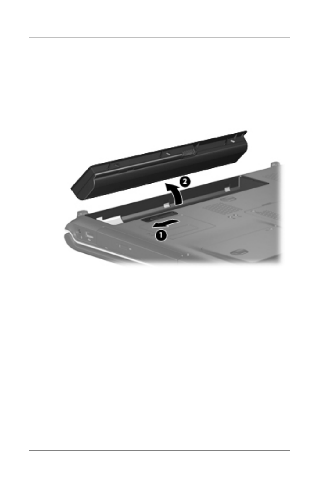
5–6 Maintenance and Service Guide
Removal and Replacement Procedures
b. Slide and hold the battery release latch 1 to the left.
(The front edge of the battery disengages from
the computer.)
c. Lift the front edge of the battery 2 and swing it back.
d. Remove the battery.
Removing the Battery
Reverse the above procedure to install the battery.

Removal and Replacement Procedures
Maintenance and Service Guide 5–7
5.4 Hard Drive
Hard Drive Spare Part Number Information
Hard drives (include bracket and connector)
For use only with computer models using Intel processors:
100-GB (7200-rpm)
100-GB (5400-rpm)
434662-001
432997-001
For use with all computer models:
200-GB (4200-rpm)
160-GB (5400-rpm)
120-GB (5400-rpm)
100-GB (7200-rpm)
80-GB (5400-rpm)
441424-001
438485-001
432998-001
441540-001
432996-001
For use only with computer models using AMD processors:
120-GB (7200-rpm) 458116-001
Hard Drive Bracket Kit 434106-001
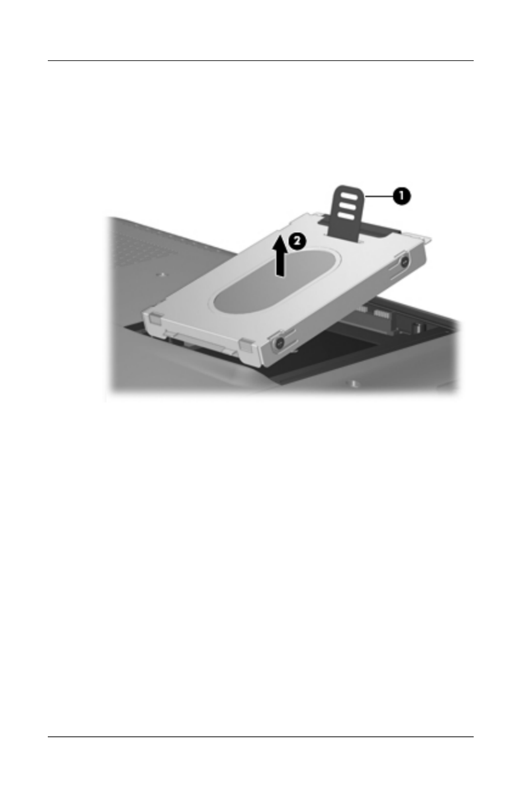
Removal and Replacement Procedures
Maintenance and Service Guide 5–9
5. Use the mylar tab 1 to lift the hard drive 2 until it
disconnects from the computer.
6. Remove the hard drive from the hard drive bay.
Removing the Hard Drive

5–10 Maintenance and Service Guide
Removal and Replacement Procedures
7. Remove the four Phillips PM3.0×3.0 screws 1 that secure
the hard drive bracket to the hard drive.
8. Lift the bracket straight up to remove it from the 2
hard drive.
✎The hard drive bracket and the screws used to secure the
bracket to the hard drive are included in the Hard Drive
Bracket Kit, spare part number 434106-001.
Removing the Hard Drive Bracket
Reverse the above procedure to install and reassemble the
hard drives.

Removal and Replacement Procedures
Maintenance and Service Guide 5–11
5.5 Computer Feet
The computer feet are adhesive-backed rubber pads. The feet are
included in the Rubber Feet Kit, spare part number 432982-001.
The feet attach to the base enclosure in the locations illustrated
below.
Computer Feet Locations

5–12 Maintenance and Service Guide
Removal and Replacement Procedures
5.6 Memory Module
1. Prepare the computer for disassembly (refer to Section 5.3).
Memory Module Spare Part Number Information
Memory modules, PC-5300, 667-MHz, 1-DIMM
For use only with models using Intel processors:
1024-MB
512-MB
434742-001
434741-001
For use only with models using AMD processors:
2048-MB
1024-MB
512-MB
448003-001
432970-001
432969-001

Removal and Replacement Procedures
Maintenance and Service Guide 5–13
2. Loosen the two captive Phillips PM2.0×5.0 screws 1 that
secure the memory module compartment cover to the
computer.
3. Lift the front of the memory module compartment cover 2,
and then swing it back.
4. Remove the memory module compartment cover.
✎The memory module compartment cover is included in the
Plastics Kit, spare part number 432981-001.
Removing the Memory Module Compartment Cover

Removal and Replacement Procedures
Maintenance and Service Guide 5–15
5.7 RTC Battery
1. Prepare the computer for disassembly (refer to Section 5.3).
2. Remove the memory module compartment cover
(Section 5.6).
3. Disconnect the RTC battery cable 1 from the system board.
4. Remove the RTC battery 2.
✎The RTC battery is secured to the computer by 2-sided tape.
All replacement RTC battery spare part kits include
2-sided tape.
Removing the RTC Battery
Reverse the above procedure to install the RTC battery.
RTC Battery Spare Part Number Information
RTC battery (includes 2-sided tape) 431436-001

5–16 Maintenance and Service Guide
Removal and Replacement Procedures
5.8 Mini Card Module
Mini Card Module
Spare Part Number Information
For use only with models using Intel processors:
802.11a/b/g WLAN Mini Card module for use in the MOW1
countries and regions listed below:
407674-001
Antigua &
Barbuda
Argentina
Australia
Bahamas
Barbados
Canada
Chile
Dominican
Republic
Guam
Guatemala
Panama
India
Indonesia
Malaysia
Mexico
New Zealand
Paraguay
Saudi Arabia
Taiwan
The United States
Vietnam
802.11a/b/g WLAN Mini Card module for use in the MOW2
countries and regions listed below:
407674-002
Aruba
Austria
Azerbaijan
Bahrain
Belgium
Bermuda
Bulgaria
Cayman Islands
Columbia
Croatia
Cyprus
The Czech
Republic
Denmark
Egypt
El Salvador
Estonia
Finland
France
Georgia
Germany
Greece
Hungary
Iceland
Ireland
Italy
Latvia
Lebanon
The Philippines
Poland
Portugal
Romania
Russia
Serbia and
Montenegro
Singapore
Slovakia
Liechtenstein
Lithuania
Luxembourg
Malta
Monaco
The
Netherlands
Norway
Oman
Slovenia
South Africa
Spain
Sri Lanka
Sweden
Switzerland
Turkey
The United
Kingdom
Uzbekistan

Removal and Replacement Procedures
Maintenance and Service Guide 5–21
8. Remove the optical drive bracket 2.
Removing the Optical Drive Bracket
Reverse the above procedure to reassemble and install the
optical drive.

5–22 Maintenance and Service Guide
Removal and Replacement Procedures
5.10 Switch Cover
1. Prepare the computer for disassembly (Section 5.3).
2. Close the computer.
3. Turn the computer upside down with the front panel
toward you.
4. Remove the six Phillips PM2.0×5.0 screws that secure the
switch cover to the computer.
Switch Cover Spare Part Number Information
Switch cover (includes LED board and LED
board cable), for model dv9000
Switch cover (includes LED board and LED
board cable), for model dv9200
Switch cover (includes LED board and LED
board cable), for model dv9200 for EMEA only
432979-001
438319-001
442920-001

Removal and Replacement Procedures
Maintenance and Service Guide 5–23
Removing the Switch Cover Screws

5–24 Maintenance and Service Guide
Removal and Replacement Procedures
5. Turn the computer display-side up with the front toward you.
6. Open the computer as far as possible.
7. Lift the rear edge of the switch cover and swing it forward
until it rests on the keyboard.
Releasing the Switch Cover

5–26 Maintenance and Service Guide
Removal and Replacement Procedures
5.11 Keyboard
1. Prepare the computer for disassembly (Section 5.3).
2. Remove the switch cover (Section 5.10).
Keyboard Spare Part Number Information
For use in the following countries and regions:
Belgium
Denmark,
Finland,
Norway,
and Sweden
France
French Canada
Germany
Greece
Israel
Italy
Japan
441541-A41
441541-DH1
441541-051
441541-121
441541-041
441541-151
441541-BB1
441541-061
441541-291
Latin America
Netherlands
Portugal
Russia
Saudi Arabia
Spain
Switzerland
Thailand
Tu rkey
United Kingdom
United States
441541-161
441541-B31
441541-131
441541-251
441541-171
441541-071
441541-111
441541-281
441541-141
441541-031
441541-001
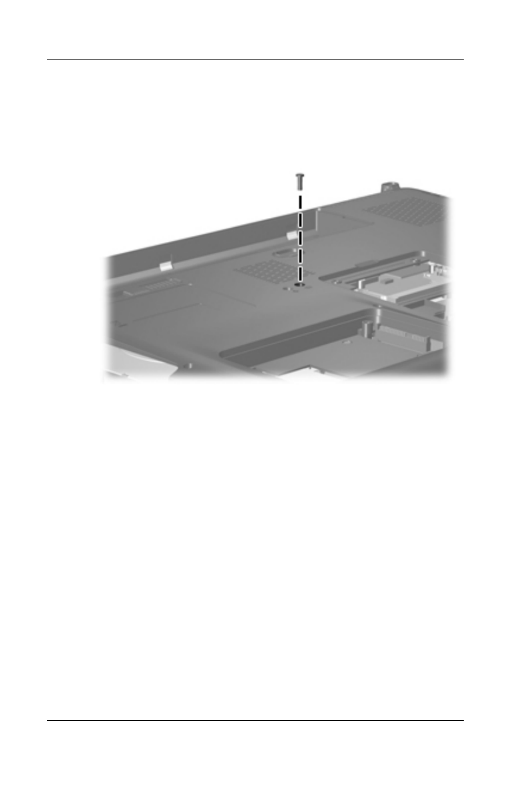
Removal and Replacement Procedures
Maintenance and Service Guide 5–27
3. Remove the Phillips PM2.5×7.0 screw that secures the
keyboard to the computer.
Removing the Keyboard Screw, Part 1

5–28 Maintenance and Service Guide
Removal and Replacement Procedures
4. Turn the computer display-side up with the front panel
toward you.
5. Open the computer as far as possible.
6. Remove the three silver Phillips PM2.5×5.0 screws that
secure the keyboard to the computer.
Removing the Keyboard Screws, Part 2

5–30 Maintenance and Service Guide
Removal and Replacement Procedures
10. Release the ZIF connector 1 to which the keyboard cable is
connected and disconnect the keyboard cable 2 from the
system board.
Disconnecting the Keyboard Cable
11. Remove the keyboard.
Reverse the above procedure to install the keyboard.

Removal and Replacement Procedures
Maintenance and Service Guide 5–37
5. Turn the computer display-side up with the front toward you.
6. Open the computer to an upright position.
7. Disconnect the display cable 1 from the system board and
the microphone cable 2 from the power button board.
8. Remove the wireless antenna cables and the camera cable
from the clips 3 in the top cover.
9. Disconnect the camera cable 4 from the system board.
Disconnecting the Display Cables

5–38 Maintenance and Service Guide
Removal and Replacement Procedures
ÄCAUTION: Support the display assembly when removing the following
screws. Failure to support the display assembly can result in damage to
the display assembly and other computer components.
10. Remove the two Phillips PM2.5×8.0 screws 1 and the
two silver Phillips PM2.5×5.0 screws 2 that secure
the display assembly to the computer.
11. Remove the display assembly 3.
Removing the Display Assembly

Removal and Replacement Procedures
Maintenance and Service Guide 5–39
12. Remove the following:
1 Three rubber screw covers on the display bezel top edge
2 Two rubber screw covers on the display bezel bottom edge
3 Five Phillips PM2.5×8.0 screws
✎The display rubber screw covers are included in the Display
Screw Kit, spare part number 432967-001.
Removing the Display Bezel Screws

5–40 Maintenance and Service Guide
Removal and Replacement Procedures
13. Flex the inside edges of the left and right sides 1 and the
top and bottom sides 2 of the display bezel until the bezel
disengages from the display enclosure.
14. Remove the display bezel 3.
Removing the Display Bezel
Display Assembly Subcomponents
Spare Part Number Information
Display bezels
For use with Dual Lamp display panels with camera
For use with Dual Lamp display panels without camera
432956-001
436068-001
For use with Single Lamp display panels with camera
For use with Single Lamp display panels without camera
432955-001
436067-001

5–42 Maintenance and Service Guide
Removal and Replacement Procedures
17. Remove the inverter 1 from the display enclosure.
18. Disconnect the display cable 2 and the backlight cable 3
from the display inverter.
Removing the Display Inverter
Display Assembly Subcomponents
Spare Part Number Information
Display inverters
For use with Dual Lamp display panels
For use with Single Lamp display panels
432959-001
431391-001

Removal and Replacement Procedures
Maintenance and Service Guide 5–43
19. Remove the six Phillips PM2.5×8.0 screws 1 that secure
the display panel to the display enclosure.
20. Remove the display panel 2.
Removing the Display Panel
Display Assembly Subcomponents
Spare Part Number Information
Display panels
17.0-inch, WXGA+, TFT Dual Lamp display panel with
BrightView
17.0-inch, SXGA+, TFT Single Lamp display panel with
BrightView
17.0-inch, WXGA+, TFT Single Lamp display panel with
BrightView
432954-001
432953-001
432952-001

5–44 Maintenance and Service Guide
Removal and Replacement Procedures
21. Remove the two Phillips PM2.0×3.0 screws 1 that secure
each display hinge to the display enclosure.
22. Remove the display hinges 2.
23. Slide the left and right display hinge covers 3 off of the
display hinges.
Removing the Display Hinges
Display Assembly Subcomponents
Spare Part Number Information
Display Hinge Kits
For use with Dual Lamp display panels
For use with Single Lamp display panels
432964-001
432963-001
Display hinge covers 432965-001

5–46 Maintenance and Service Guide
Removal and Replacement Procedures
28. If it is necessary to replace the microphones and cables,
release the retention tabs 1 built into the display enclosure
that secure the microphone cables to the display enclosure.
29. Remove the microphone receivers 2 from the clips in the
display enclosure.
30. Remove the microphone cables 3 from the
display enclosure.
Removing the Microphones
Display Assembly Subcomponents
Spare Part Number Information
Microphones 432961-001

Removal and Replacement Procedures
Maintenance and Service Guide 5–47
31. If it is necessary to replace the camera cable, release the
retention tabs 1 built into the display enclosure that secure
the camera cable to the display enclosure.
32. Remove the camera cable 2 from the display enclosure.
Removing the Camera Cable
Reverse the above procedure to reassemble and install the
display assembly
Display Assembly Subcomponents
Spare Part Number Information
Display Cable Kit (includes camera cable) 432962-001
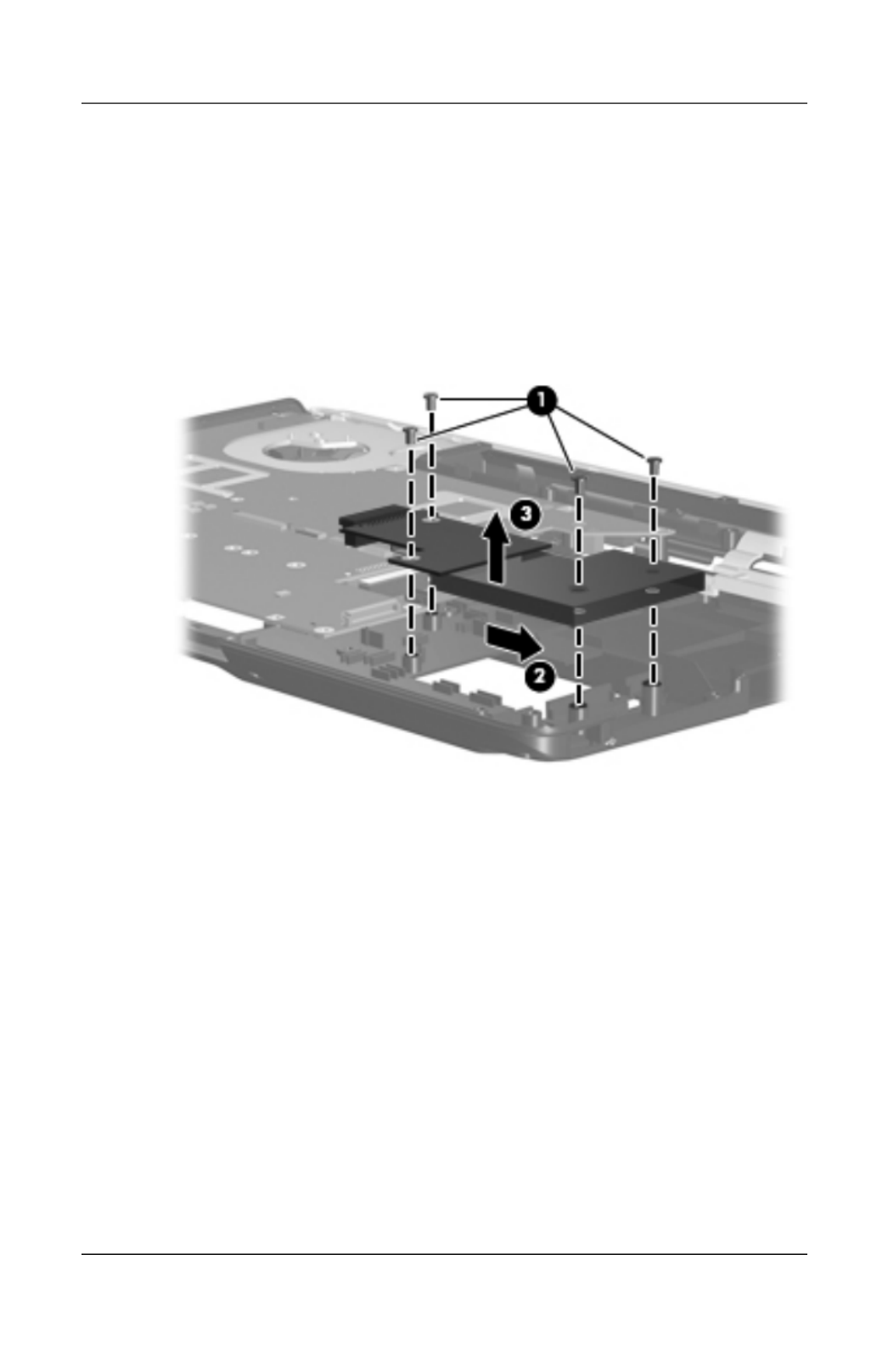
Removal and Replacement Procedures
Maintenance and Service Guide 5–65
4. Remove the four silver Phillips PM2.5×5.0 screws 1 that
secure the ExpressCard assembly to the system board.
5. Slide the ExpressCard assembly 2 to the right to disconnect
it from the system board.
6. Remove the ExpressCard assembly 3.
Removing the ExpressCard Assembly
Reverse the above procedure to install the ExpressCard assembly.

Removal and Replacement Procedures
Maintenance and Service Guide 5–67
2. Turn the computer upside down with the front toward you.
3. Remove the four Phillips PM2.5×8.0 screws that secure the
top cover support trim to the computer.
Removing the Top Cover Support Trim Screws
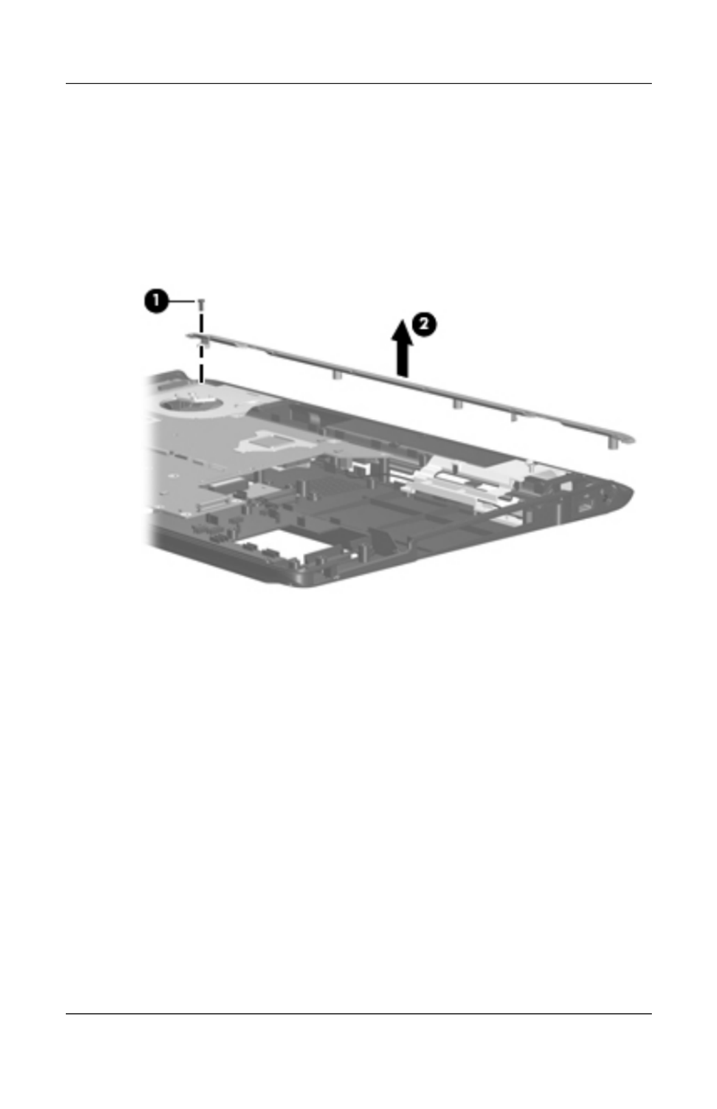
5–68 Maintenance and Service Guide
Removal and Replacement Procedures
4. Turn the computer right-side up with the front toward you.
5. Remove the Phillips PM2.5×8.0 screw 1 that secures the top
cover support trim to the computer.
6. Remove the top cover support trim 2.
Removing the Top Cover Support Trim
Reverse the above procedure to install the top cover support trim.

5–70 Maintenance and Service Guide
Removal and Replacement Procedures
2. Remove the display lid switch module by firmly pulling it
off the fan/heat sink assembly.
✎The display lid switch module is secured to the fan/heat sink
assembly by 2-sided tape. Apply removal force to the middle
of the module to remove it.
Removing the Display Lid Switch Module
✎The display lid switch module cable is included with the
display lid switch module spare part kit and is also included in
the Cable Kit, spare part number 434677-001.
Reverse the above procedure to install the display lid
switch module.

Removal and Replacement Procedures
Maintenance and Service Guide 5–71
5.23 Power Connector Assembly
1. Prepare the computer for disassembly (Section 5.3) and
remove the following components:
❏Hard drive (Section 5.4)
❏Optical drive (Section 5.9)
❏Switch cover (Section 5.10)
❏Keyboard (Section 5.11)
❏Speaker assembly (Section 5.12)
❏Display assembly (Section 5.14)
❏Top cover (Section 5.15)
Power Connector Assembly Spare Part Number Information
Power connector assembly (includes power connector assembly
cable and power connector assembly bracket)
432985-001
USB board 432989-001

Removal and Replacement Procedures
Maintenance and Service Guide 5–73
4. Remove the silver Phillips PM2.5×5.0 screw 1 that secures
the USB board to the computer.
5. Remove the USB board 2.
6. Disconnect the USB board cable 3 from the USB board and
remove the cable from the clips 4 in the base enclosure.
✎The USB board cable is included with the USB board spare
part kit and is also included in the Cable Kit, spare part number
434677-001.
Removing the USB Board

Removal and Replacement Procedures
Maintenance and Service Guide 5–75
5.24 System Board
✎When replacing the system board, ensure that the following
components are removed from the defective system board and
installed on the replacement system board:
■Memory modules (Section 5.6)
■RTC battery (Section 5.7)
■Mini Card module (Section 5.8)
■Bluetooth module (Section 5.18)
■ExpressCard assembly (Section 5.20)
■Optical drive connector module (Section 5.24)
■Fan/heat sink assembly (Section 5.25)
■Processor (Section 5.26)
1. Prepare the computer for disassembly (Section 5.3) and
remove the following components:
❏Hard drive (Section 5.4)
❏Optical drive (Section 5.9)
❏Switch cover (Section 5.10)
❏Keyboard (Section 5.11)
❏Speaker assembly (Section 5.12)
❏Display assembly (Section 5.14)
System Board Spare Part Number Information
For use with only computer models using Intel processors:
G73 (includes 512-MB of video RAM)
G73M (includes 256-MB of video RAM)
G73 (includes 512 MB of video RAM) - for Germany only
G73 (includes 256 MB of video RAM) - for EMEA only
434660-001
434659-001
441620-001
445178-001
For use only with UMA computer models using AMD processors 444002-001

5–76 Maintenance and Service Guide
Removal and Replacement Procedures
❏Top cover (Section 5.15)
❏Wireless switch board (Section 5.16)
❏Audio board (Section 5.17)
❏USB/magnetic board (Section 5.19)
❏Top cover support trim (Section 5.21)
❏USB board (Section 5.23)
❏Power connector assembly (Section 5.23)
2. Turn the computer upside down with the front toward you.
3. Remove the Phillips PM2.5×8.0 screw that secures the
system board to the base enclosure.
Removing the System Board Screw, Part 1

Removal and Replacement Procedures
Maintenance and Service Guide 5–77
4. Remove the three Phillips PM2.5×8.0 screws 1 and the three
silver Phillips PM2.5×5.0 screws 2 that secure the system
board to the base enclosure.
Removing the System Board Screws, Part 2

Removal and Replacement Procedures
Maintenance and Service Guide 5–79
9. If it is necessary to replace the power connector assembly or
the USB board cable, turn the system board upside down with
the front toward you.
10. Disconnect the power connector assembly cable 1 and the
USB board cable 2 from the system board.
Removing the System Board Cables
Reverse the above procedure to install the system board, power
connector assembly, and audio board cable.
Produktspecifikationer
| Varumärke: | HP |
| Kategori: | Laptop |
| Modell: | Pavilion dv9000 |
Behöver du hjälp?
Om du behöver hjälp med HP Pavilion dv9000 ställ en fråga nedan och andra användare kommer att svara dig
Laptop HP Manualer

5 Mars 2025
2 Februari 2025
2 Februari 2025
2 Februari 2025
2 Februari 2025
2 Februari 2025
2 Februari 2025
2 Februari 2025
7 Januari 2025
28 December 2024
Laptop Manualer
- Laptop Sony
- Laptop Samsung
- Laptop Xiaomi
- Laptop LG
- Laptop Huawei
- Laptop Panasonic
- Laptop Medion
- Laptop Toshiba
- Laptop Acer
- Laptop Alienware
- Laptop Apple
- Laptop Airis
- Laptop Lexibook
- Laptop Thomson
- Laptop Pyle
- Laptop Emachines
- Laptop Asus
- Laptop Hyundai
- Laptop Micromax
- Laptop Lenovo
- Laptop Hähnel
- Laptop Denver
- Laptop Tripp Lite
- Laptop Schneider
- Laptop Gigabyte
- Laptop Sylvania
- Laptop Microsoft
- Laptop Haier
- Laptop Coby
- Laptop Fujitsu
- Laptop Razer
- Laptop Goclever
- Laptop Fellowes
- Laptop Evga
- Laptop Dell
- Laptop Honor
- Laptop Naxa
- Laptop Mpman
- Laptop Vizio
- Laptop MSI
- Laptop Targa
- Laptop Zebra
- Laptop Viewsonic
- Laptop Peaq
- Laptop Ematic
- Laptop Hannspree
- Laptop ADATA
- Laptop XPG
- Laptop ECS
- Laptop Inovia
- Laptop Odys
- Laptop SPC
- Laptop Ibm
- Laptop Atdec
- Laptop SIIG
- Laptop Hercules
- Laptop Oregon Scientific
- Laptop Kogan
- Laptop Getac
- Laptop Jay-tech
- Laptop Vulcan
- Laptop System76
- Laptop Prixton
- Laptop General Dynamics Itronix
- Laptop CTL
- Laptop Everex
- Laptop Olidata
- Laptop Dynabook
- Laptop Hamilton Buhl
- Laptop AORUS
- Laptop Humanscale
- Laptop TechBite
- Laptop Aplic
- Laptop Schenker
Nyaste Laptop Manualer

28 Mars 2025
28 Mars 2025
26 Mars 2025
11 Februari 2025
11 Februari 2025
11 Februari 2025
31 Januari 2025
31 Januari 2025
28 Januari 2025
28 Januari 2025