Kramer 691 Bruksanvisning
Kramer
AV extender
691
Läs nedan 📖 manual på svenska för Kramer 691 (73 sidor) i kategorin AV extender. Denna guide var användbar för 6 personer och betygsatt med 4.5 stjärnor i genomsnitt av 2 användare
Sida 1/73

P/N: - Rev 5 2900 300523 www.KramerAV.com
USER MANUAL
MODEL:
691 HDBT 2.0 Optical Transmitter

691 Contents–
i
Contents
1 Introduction 1
2 Getting Started 2
2.1 Achieving the Best Performance 2
2.2 Safety Instructions 2
2.3 Recycling Kramer Products 3
3 Overview 4
4 Dening the 691 HDBT 2.0 Optical Transmitter 7
5 Connecting the 691 HDBT 2.0 Optical Transmitter 9
5.1 Using the OSP SFP+ Module 12
5.2 Connecting to 691 via RS-232 16
5.3 Connecting 691 via the Ethernet Port 17
6 Principles of Operation 21
6.1 Audio Output 21
6.2 Video Output and Audio Switching Timeouts 21
6.3 Controlling A/V Equipment via an IR Remote Control 21
7 Conguring the 691 HDBT 2.0 Optical Transmitter 24
8 Using the Embedded Web Pages 25
8.1 Browsing the 691 Web Pages 25
8.2 Setting the Sleep Mode, HDCP Mode and Audio Switching Delay Time 27
8.3 Setting Device Parameters 29
8.4 Managing the EDID 33
8.5 Authentication Page 35
8.6 Viewing the About Page 36
9 Firmware Upgrade 37
10 38 Technical Specications
10.1 Default Communication Parameters 40
10.2 Default Parameters 40
10.3 Default EDID 41
11 43 Protocol 3000
11.1 Understanding Protocol 3000 44
11.2 Kramer Protocol 3000 Syntax 46
11.3 Protocol 3000 Commands 47

ii
691 - Contents
Figures
Figure 1: 691 Front Panel 7
Figure 2: 691 Rear Panel 8
Figure 3: Connecting the 691 and 692 9
Figure 4: Connecting the Fiber Optic Cable 10
Figure 5: System Layout Example for Optical Reach Evaluation 14
Figure 6: Inserting the Transceiver Module 15
Figure 7: RS-232 Connection 16
Figure 8: Local Area Connection Properties Window 18
Figure 9: Internet Protocol Version 4 Properties Window 19
Figure 10: Internet Protocol Version 6 Properties Window 19
Figure 11: Internet Protocol Properties Window 20
Figure 12: Controlling a Blu-ray Disk Player via the 692 Receiver 22
Figure 13: Controlling a Projector via the 691 Transmitter 23
Figure 14: 691 DIP-Switch 24
Figure 15: Entering Logon Credentials 26
Figure 16: Video & Audio Settings Page 27
Figure 17: The Device Settings Page 30
Figure 18: Turning DHCP Off Dialog Box 30
Figure 19: Turning DHCP On Warning 31
Figure 20: The EDID Management Page 34
Figure 21: The EDID Message 34
Figure 22: The Authentication Page 35
Figure 23: The About Page 36

691 - Introduction
1
1 Introduction
Welcome to Kramer Electronics! Since 1981, Kramer Electronics has been
providing a world of unique, creative, and aordable solutions to the vast range of
problems that confront video, audio, presentation, and broadcasting professionals
on a daily basis. In recent years, we have redesigned and upgraded most of our
line, making the best even better!
Congratulations on purchasing your Kramer HDBT 2.0 Optical Transmitter 691
which part of the Kramer Video and Audio Distribution System and ideal for: is is
• Ultra-long signals extension for:
▪ Multi-room and inter-building ultra-long connectivity.
▪ Large dividable auditoriums and lecture halls.
• Highly secured and reliable signals ultra-long extension for:
▪ Governmental applications.
▪ Medical applications.
▪ Rental and staging applications.
691 692 HDBT 2.0 Optical Transmitt and er HDBT 2.0 Optical
Receiver are standard complia and can be connected to other nt
HDBT-certied transmitters and receivers.

2
691 - Getting Started
2 Getting Started
We recommend that you:
• Unpack the equipment carefully and save the original box and packaging
materials for possible future shipment.
• Review the contents of this user manual.
Go to to check for up- -date user www.kramerav.com/downloads/691 to
manuals, application programs, and to check if rmware upgrades are
available (where appropriate).
2.1 Achieving the Best Performance
To achieve the best performance:
• Use only good quality connection cables (we recommend Kramer high-
performance, high-resolution cables) to avoid interference, deterioration in
signal quality due to poor matching, and elevated noise levels (often
associated with low quality cables).
• Do not secure the cables in tight bundles or roll the slack into tight coils.
• Avoid interference from neighboring electrical appliances that may adversely
inuence signal quality.
• Position your 691 HDBT 2.0 Optical Transmitter away from moisture,
excessive sunlight and dust.
This equipment is to be used only inside a building. It may only be
connected to other equipment that is installed inside a building.
2.2 Safety Instructions
Caution:
There are no operator serviceable parts inside the unit.
Warning:
Use only the power cord that is supplied with the unit.
Warning:
Disconnect the power and unplug the unit from the wall
before installing.

691 - Getting Started
3
2.3 Recycling Kramer Products
The Waste Electrical and Electronic Equipment (WEEE) Directive 2002/96/EC
aims to reduce the amount of WEEE sent for disposal to landll or incineration by
requiring it to be collected and recycled. To comply with the WEEE Directive,
Kramer Electronics has made arrangements with the European Advanced
Recycling Network (EARN) and will cover any costs of treatment, recycling and
recovery of waste Kramer Electronics branded equipment on arrival at the EARN
facility. For details of Kramer’s recycling arrangements in your particular country
go to our recycling pages at . www.kramerav.com/support/recycling/

4
691 - Overview
3 Overview
691 is a high-performance HDBaseT 2.0 ber transmitter for ultra-reach extension
of 4K60Hz (4:2:0) HDMI, USB 2.0, Ethernet, RS-232, IR and stereo audio signals
over either multi-mode or single-mode ber optic. converts all input signals to
691
an HDBaseT 2.0 signal at is transmitted over ber optic cable to a compatible th
receiver (such as Kramer ) that converts it back to the HDMI, USB 2.0, 692
Ethernet, RS-232, IR and stereo audio output signals .
691 tends video signals to up to 33km (20.5 miles) over single-mode ber at up ex
to 4K@60Hz (4:2:0) resolution. includes a multimode OSP+ transceiver 691
(Kramer OSP-MM1), but can be used with a single mode OSP+ transceiver and
ber as well.
The transmitter features:
691
• High performance standard ber extender HDBaseT 2.0 ber transmitter for –
providing ultra-reach signals over either multi-mode or single-mode optical
ber infrastructures, using Kramer pluggable OSP SFP+ units. is a
691
standard fiber extender that can be connected to any market-available
HDBaseT-compliant extension product.
To ensure Kramer support and warranty of the product, use only 691
Kramer's certied high-performance OSP SFP+ pluggable optical
modules:
OSP-MM1: Optical 850nm 10G SFP+ Transceiver (included). MM
OSP-SM10: Optical SM 1310nm SFP+ Transceiver (can be 10G
purchased separately).
For optimum extension reach and performance, use Kramer's OSP SFP+
units and recommended Kramer cables. Non-Kramer cables may not
reach these ranges.
Note that the maximum transmission reach is typical and may vary
depending on ber cables performance, signal resolution, connectors and
splicing optical losses, modal or chromatic dispersion, and similar optical-
related factors.

691 - Overview
5
• HDMI signal extension HDCP 1.4 compliant. Supports deep color, –
x.v.Color™, lip sync, HDMI uncompressed audio channels, Dolby TrueHD,
DTS-HD, 2K, 4K, and 3D as specied in HDMI 2.0. EDID and CEC signals
are passed through from the source to the display.
• I- Intelligent EDID EDIDPro™ Kramer Intelligent EDID Processing™ –
handling, processing and pass-through algorithm that ensures Plug-and-Play
operation for HDMI source and display systems.
• USB extension USB 2.0 interface data ows in both directions, allowing –
extension of HID (Human Interface Devices) peripheral devices, such as a
mouse or a keyboard. High-bandwidth USB peripheral devices, such as USB
isochronous streaming cameras and audio devices, transfer data continuously
and periodically.
Delivery of the transferred data is not guaranteed by the USB standard
and is subject to both USB and HDBaseT line bandwidth management
limitations. When such devices are connected, check their functionality to
ensure bandwidth limitations are not exceeded.
• Ethernet extension Ethernet interface data ows in both directions allowing –
extension of up to 100Mbps Ethernet connectivity for LAN communication and
device control.
• Bidirectional RS-232 extension Serial interface data ows in both directions –
allowing data transmission and device control.
• Bidirectional infrared extension IR interface data ows in both directions –
allowing remote control of peripheral devices located at either end of the
extended line.
• Audio embedding (Adding) A selectable analog unbalanced stereo audio –
input is converted into a digital signal and added (embedded) to the
transmitted HDMI signal, replacing the embedded HDMI audio input signal.
This enables embedding a selectable audio source over HDMI. For example,
a presenter can display a video clip and temporarily override the audio of the
source media with another audio source, such as from a microphone.

6
691 - Overview
• Cost-eective maintenance Status LED indicators for the HDMI input and –
HDBT output link facilitate easy local troubleshooting. Remote device
management via built-in web UI and RS-232 connection enable simple
device maintenance. Kramer Network support provides remote device and
network management. Local and remote rmware upgrade via mini-USB,
RS-232 or Ethernet connection and the K-Upload tool ensure lasting,
eld-proven deployment.
• Easy installation -less enclosure enables – Half 19” 1U rack mountable fan
side- -side mounting of 2 units in a 1U rack space. by
691 - Dening the 691 HDBT 2.0 Optical Transmitter
7
4 Dening the HDBT 2.0 Optical 691
Transmitter
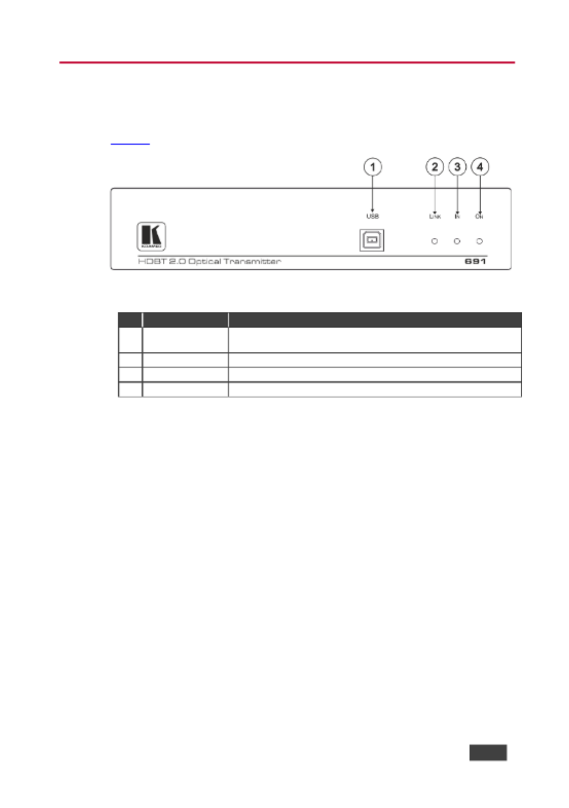
Figure 1 denes the front panel of the . 691
Figure 1 691 Front Panel :
#
Feature
Function
1
USB Connector
Connect to the USB host for trac extension (for example, a
laptop) for trac extension to remote connected USB devices.
2
LINK LED
Lights green when the HDBT link is valid.
3
IN LED
Lights green when an HDMI active signal device is connected.
4
ON LED
Lights green when the device receives power.

8
691 - Dening the 691 HDBT 2.0 Optical Transmitter
Figure 2 denes the rear panel of the . 691
Figure 2 691 Rear Panel :
#
Feature
Function
5
HDMI IN Connector
Connect to an HDMI source.
6
IR 3.5mm Mini Jack
Connector
Connect to an external infrared transmitter or sensor
for trac extension.
7
RS- 3-pin Terminal Block 232
Connect to an RS-232 controller for trac extension
(for example, a PC to control the projector).
8
AUDIO IN 3.5mm Mini Jack
Connect to the stereo, unbalanced, analog audio
source.
9
OUT IN SFP+ Connector
Connect the ber optic cable to the OUT IN SFP+
connectors ( included see ).
OSP-MM1 , Section 5.1
10
SETUP 4-way DIP-switch
Sets the device behavior, (see ). Section 7
11
CONTROL
RS- 3-pin 232
Terminal Block
Connect to a serial controller to control this device.
12
ETHERNET
RJ-45
Connector
Connect to the LAN to extend network trac to the
receiver Ethernet controller to control this device. and
13
RESET Switch
Press and hold for 5 seconds to reset the device to
factory default settings.
Press and immediately release to power-cycle the
device (Reset).
14
PROG Mini USB Connector
Use for rmware upgrade.
15
12V DC Power Connector
Connect to the supplied power adapter.

691 - Connecting the 691 HDBT 2.0 Optical Transmitter
9
5 Connecting the 691 HDBT 2.0 Optical
Transmitter
Always switch o the power to each device before connecting it to
your . After connecting your , connect the power to and switch
691 691
on each device.
You can use the HDBT 2.0 Optical Transmitter and a compatible receiver, for 691
example, the Kramer HDBT 2.0 Optical Receiver to congure a paired HDMI 692
transmitter/receiver system, as shown in the example in . Figure 3
Figure 3 Connecting the and 692 : 691

10
691 - Connecting the 691 HDBT 2.0 Optical Transmitter
To connect the 691 HDBT 2.0 Optical Transmitter :
1. Connect HDMI source, (for example, a ) to the HDMI IN connector. an PC
2. Connect an -232 serial controller to the RS-232 3-pin terminal block for RS
trac extension, to control the projector (on the receiver side).
3. Connect a stereo analog audio source (for example, the audio output of a
PC) to the AUDIO IN 5mm mini jack for trac extension. 3.
4. Connect the USB port on a to the USB port on the front panel of the PC 691
for trac extension.
5. Connect an external IR sensor to the 3.5mm mini jack for trac IR
extension.
6. Connect the OUT IN SFP+ (UPC) connector to the OUT/IN LC(UPC) ber LC
optic cable extension towards the receiver.
692
By default, is installed in the (see ) To OSP-MM1 691 Section 5.1 .
replace with a dierent Kramer-certied MM SFP+ OSP-MM1
transceiver, see Section 5.1.2.
Always cross-connect the ber connections, Rx OUT to Tx IN and Rx IN
to Tx OUT, as transmission is carried on simplex ber strands.
Figure 4: Connecting the Fiber Optic Cable

691 - Connecting the 691 HDBT 2.0 Optical Transmitter
11
Always inspect and clean the connectors before you make a connection.
Always plug or unplug the ber by holding the connector housing.
Never touch the end face of the optic ber connectors.
7. Connect the supplied power adapter to the power socket and plug the
adapter to the mains electricity (not shown in in Figure 3).
To connect the optical receiver (for example, the 692):
1. Connect the HDMI OUT connector to HDMI acceptor, (for example, a an
projector).
2. Connect the 3-pin terminal block to the device to be controlled (for RS-232
example, the projector to be controlled by a serial controller which is
connected to
691).
3. Connect the AUDIO OUT 3.5mm mini jack to audio acceptor, (for an
example, amplied speakers).
4. Connect the USB ports (for example, USB keyboard and mouse and a USB
camera ).
5. Connect the IR 3.5mm mini jack to an IR emitter.

12
691 - Connecting the 691 HDBT 2.0 Optical Transmitter
6. Connect the OUT IN SFP+ LC(UPC) connector to the IN/OUT LC(UPC)
connector of the ber optic cable extension towards the transmitter.
691
By default, is installed in the (see ). To replace OSP-MM1 692 Section 5.1
OSP-MM1 with a dierent Kramer-certied MM SFP+ transceiver,
see Section 5.1.2.
Always cross-connect the ber connections, Rx OUT to Tx IN and Rx IN
to Tx OUT, as transmission is carried on simplex ber strands (see
Figure 4).
Always inspect and clean the connectors before you make a connection.
Always plug or unplug the fiber by holding the connector housing.
Never touch the end face of the ber connectors.
7. Connect the supplied power adapter to the power socket and plug the
adapter to the mains electricity (not shown in in Figure 3).
5.1 Using t OSP SFP+ Module he
By default, is inserted in OSP-MM1 691. If required, replace the optical
transceiver, you need to insert the same type of SFP+ transceiver both into the
SFP+ opening on the and the compatible receiver.
691
Two main types of Kramer SFP+ optical transceiver modules are available:
• OSP-MM1: Optical MM 850nm 10G SFP+ Transceiver (included in the
package).
• OSP-SM10: Optical SM 1310nm 10G SFP+ Transceiver (can be purchased
separately).
Before deciding to replace the default SFP+ transceiver, consider the infra-
structure of the installation area, the desired distance, optical loss budget and
typical expected loss.
U the same type of SFP+ optical transceiver module both on the se 691
transmitter and the receiver (for example, ). 692
The following table denes various typical Fiber cable characteristics, used for
optical reach evaluation:

691 - Connecting the 691 HDBT 2.0 Optical Transmitter
13
Cable Category
Core
Diameter
[ ] µm
Wavelength
Fiber
Loss
[dB/km]
Connector
Loss
[ ] dB
Splice
Loss
[ ] dB
MM OM1 [G.651.1]
62.5/125
850nm
3
Typical: 0.3
Max.: 0.75
0.3
MM OM2 [G.651.1]
50/125
MM OM3 [G.651.1,
Laser Optimized]
2.5
MM OM4 [G.651.1,
Laser Optimized]
MM OM5
SM OS1 [G.652A/B]
8
1310nm
1
SM OS2 [G.652C/D]
0.4
OSP- OSP-SM10MM1 and modules are designed to be used only with
LC(UPC) LC(PC) connectors. Using an LC(APC) blue or white green
connector with the module causes poor performance and can damage
the module connector.
For all other cable connections that do not connect directly to the
OSP- OSP-SM10MM1 or modules such as the optical patch panel and ,
bulk cables illustrated in we recommend using Angled Physical Figure 5,
Contact (APC connectors for improved end- -end reach ) green to
performance.
When using OSP modules consider the following :
• Modules are Class 1 Laser products.
• There may be Invisible laser radiation present.
• Avoid long-term viewing of laser.
• Avoid the use of magnifying viewing aids or instruments (such as
binoculars, telescopes, microscopes and magnifying lenses, but not
spectacles or contact lenses).
• Avoid placing optical devices in the emitted beam that could cause
the concentration of the laser radiation to be increased.

14
691 - Connecting the 691 HDBT 2.0 Optical Transmitter
5.1.1 Optical Reach Evaluation
The following examples show how to calculate dB loss during optical signal
transmission over ber optical infrastructure.
In the optical system layout example, illustrated in :
Figure 5
• 691 and 692 are connected to a patch panel via 100m patch cords.
• There are 6 connectors and no splices.
Figure 5 System Layout Example for Optical Reach Evaluation :
For multi-mode lines (MM OM3 cable category, as dened in the table on page 13):
• Maximum loss budget is: 8.6dB.
• Typical loss per connector is 0.3dB.
• Typical loss for each patch cord (100m) is 0.25dB.
• Fiber optic loss is 2.5 dB/km.
Multi-mode bulk line budget : 8.6 .3x6 +0.25x2) = 6.3dB. is –(0
Evaluated bulk line length is: 6.3/2.5=~2.5km.
For single-mode lines (SM OS1 cable category, as dened in the table on page 13):
• Maximum loss budget is: 11.9dB.
• Typical loss per connector is 0.3dB.
• Typical loss for each patch cord (100m) is 0.1 . dB
• Fiber optic loss is 1 dB/km.
Single-mode bulk line loss budget : 11. (0.3x6 +0.1x2) = 9.9dB. is 9 –
Evaluated bulk line length is: 9. 1=~9.9 9/ km.

691 - Connecting the 691 HDBT 2.0 Optical Transmitter
15
5.1.2 Inserting the SFP+ Module
OSP-MM1 (included in the package) comes inserted in the OUT IN SFP connector
opening of from factory. If you want to replace the with a dierent 691 OSP-MM1
SFP_ transceiver, you need to remove the installed transceiver before installing
the new one.
To insert the SFP+ module:
1. Pull the bail out and remove the currently installed transceiver, insert the
protective cap and store in a safe place.
2. Make sure the bail of the new transceiver is pushed up, in the closed
position.
3. Insert the / into the IN OUT SFP+ slot and push it in
OSP-MM1 OSP-SM10
until it clicks.
Figure 6 Inserting the Transceiver Module :
4. Remove the protective cap and keep for future use.
For more information, see the / documentation OSP-MM1 OSP-SM10
available at . www.kramerav.com/product/osp-mm1

16
691 - Connecting the 691 HDBT 2.0 Optical Transmitter
5.2 Connecting to 691 via RS-232
The features two RS-232 3-pin terminal block connectors: 691
• RS-232 to pass data to and from the machines that are connected to the
receiver.
• RS-232 CONTROL to control the 691.
Connect the RS-232 terminal block on the rear panel of the a PC/controller691 to ,
as follows (see ): Figure 7
• TX pin to Pin 2
• RX pin to Pin 3
• GND pin to Pin 5
Figure 7: RS-232 Connection

691 - Connecting the 691 HDBT 2.0 Optical Transmitter
17
5.3 Connecting 691 via the Ethernet Port
You can connect to the via Ethernet using either of the following methods: 691
• Direct to the PC using a crossover cable (see ). ly Section 5.3.1
• Via a network hub, switch, or router, using a straight-through cable (see
Section 5.3.1.1).
If you want to connect via a router and your IT system is based on IPv6,
speak to your IT department for specific installation instructions.
5.3.1 Connecting the Ethernet Port Directly to a PC
You can connect the Ethernet port of the directly to the Ethernet port on your 691
PC using a crossover cable with RJ-45 connectors.
This type of connection is recommended for identifying the with the 691
factory configured default IP address.
After connecting the to the Ethernet port, configure your PC as follows: 691
1. Click . Start > Control Panel > Network and Sharing Center
2. Click . Change Adapter Settings
3. Highlight the network adapter you want to use to connect to the device and
click . Change settings of this connection
18
691 - Connecting the 691 HDBT 2.0 Optical Transmitter
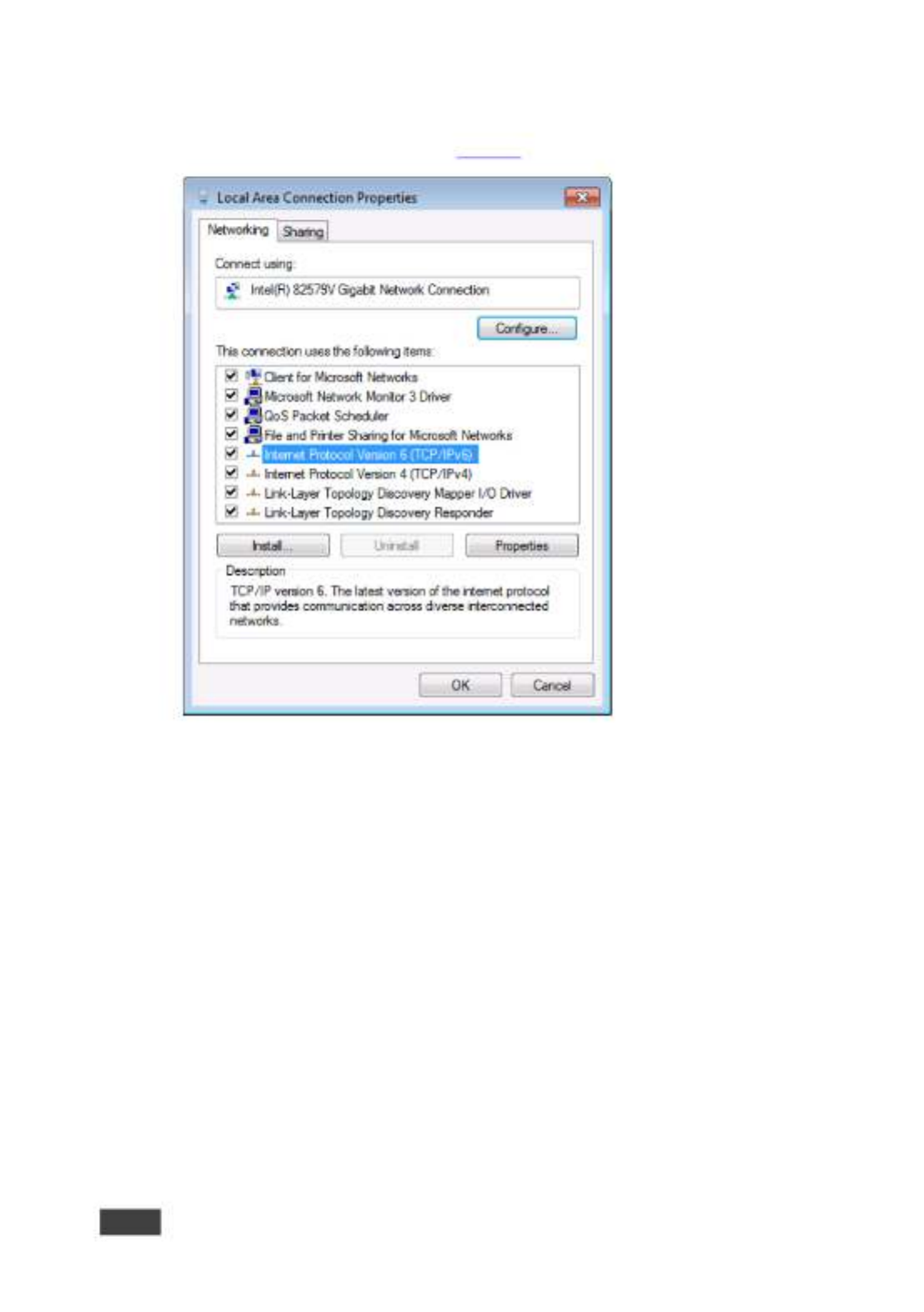
The Local Area Connection Properties window for the selected network
adapter appears as shown in .
Figure 8
Figure 8: Local Area Connection Properties Window
4. Highlight either or Internet Protocol Version 6 (TCP/IPv6) Internet
Protocol Version 4 (TCP/IPv4) depending on the requirements of your IT
system.
5. Click . Properties

691 - Connecting the 691 HDBT 2.0 Optical Transmitter
19
The Internet Protocol Properties window relevant to your IT system appears
as shown in or .
Figure 9 Figure 10
Figure 9 Internet Protocol Version 4 Properties Window :
Figure Internet Protocol Version 6 Properties Window 10:
6. Select for static IP addressing and ll in the Use the following IP Address
details as shown in .
Figure 11

20
691 - Connecting the 691 HDBT 2.0 Optical Transmitter
For TCP/IPv4 you can use any IP address in the range 192.168.1.1 to
192.168.1.255 (excluding 192.168.1.39) that is provided by your IT
department.
Figure Internet Protocol Properties Window 11:
7. Click . OK
8. Click . Close
5.3.1.1 Connecting the ETHERNET Port via a Network Hub or Switch
You can connect the Ethernet port of the to the Ethernet port on a network 691
hub or network router, via a straight-through cable with RJ-45 connectors.

691 - Principles of Operation
21
6 Principles of Operation
This section describes the audio output setup conditions, the video and audio
timeouts and AV IR control.
6.1 Audio Output
The audio source that is routed to the output depends on the SETUP DIP-switch
settings (see ) and also on whether there is an audio signal on the input
Section 7
ports. The audio output follows the rules described in the following table.
HDMI Audio
Detected
Analog Audio
Detected
DIP-switch 4
DIP-switch 2
Audio Out
N/A
N/A
Manual (On)
HDMI (O)
HDMI
N/A
N/A
Manual (On)
Analog (On)
Analog
Yes
No
Auto (O)
N/A
HDMI
Yes
Yes
Auto (O)
HDMI (O)
HDMI
Yes
Yes
Auto (O)
Analog (On)
Analog
No
Yes
Auto (O)
N/A
Analog
No
No
Auto (O)
N/A
No audio
6.2 Video Output and Audio Switching Timeouts
The device can automatically turn o the video signal output and audio source
switching after denable intervals following the loss of the input signals or
unplugging of the input cables. The delay can be set in one of two ways:
• Using the Protocol 3000 command AV- -TIMEOUTSW
(see Section 11.3.1.11).
• Using the embedded web-pages settings (see 691 Section 8.2)
If you are working with a receiver that supports setting a timeout
(e.g., ), you need to set the 5V timer only on the receiver side. 692
6.3 Controlling A/V Equipment via an IR Remote Control
Since the IR connection between the transmitter and receiver is 691 692
bidirectional, you can use a remote control transmitter (that is used for controlling
a peripheral device, for example, a Blu-ray disk player) to send commands from
either end of the transmitter or receiver system. To use a remote control
22
691 - Principles of Operation
transmitter connect the Kramer IR sensor cable at one end and the Kramer IR ,
emitter cable at the other . Two sample cases are presented below. end
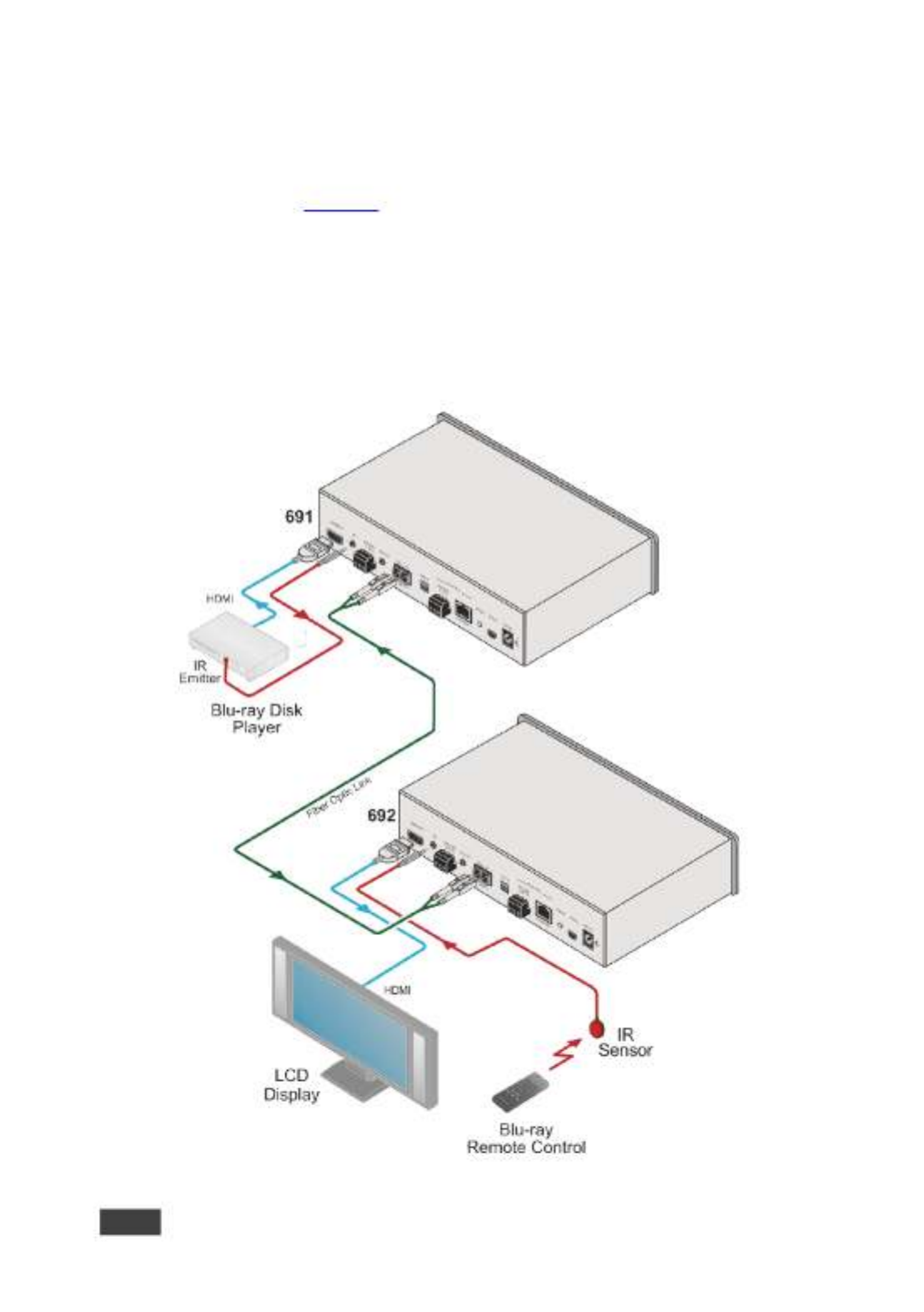
The example in illustrates how to control a -connected Blu-ray disk
Figure 12 691
player using a remote control via the remote receiver. The IR sensor cable is 692
connected to the and an IR emitter cable is connected between the and 692 691
the Blu-ray disk player. The Blu-ray disk player remote control sends an IR
command while pointed at the external IR sensor. The IR signal is passed over
the ber optic link and the IR emitter to the Blu-ray disk player which responds to
the command sent.
Figure : Controlling a Blu-ray Disk Player via the Receiver 12 692

691 - Principles of Operation
23
The example in illustrates how to remotely control the projector that is
Figure 13
connected t using an IR remote control, via the . The IR sensor cable is o 692 691
connected to the and the IR emitter cable is connected between the and 691 692
the projector. The projector remote control sends an IR command while pointed at
the external IR sensor. The IR signal is passed over the fiber optic link and the IR
emitter cable to the projector which responds to the command sent.
Figure : Controlling a Projector via the 691 Transmitter 13

24
691 - Configuring the 691 HDBT 2.0 Optical Transmitter
7 Conguring the 691 HDBT 2.0 Optical
Transmitter
The 4-way SETUP DIP-switch on the rear panel is used to congure the 691
according to the table below.
Figure DIP-Switch 14 691:
Note that all the DIP-switches are set to o (up) by default.
#
Function
Status
1
For future use
2
Audio source priority
O (up) HDMI embedded audio (factory default). –
On (down) Analog audio. –
3
EDID lock
O (up) Automatic EDID acquisition (factory –
default).
On (down) Lock (locks the current EDID so that –
changes on the output do not result in changes to the
EDID).
4
Audio mode selection
O (up) Auto (factory default). –
On (down) Manual. –
Changes to the DIP-switches only take eect on power-up. After changing
a switch, reboot the device.

691 - Using the Embedded Web Pages
25
8 Using the Embedded Web Pages
The can be managed remotely using its embedded Web pages. The Web 691
pages are accessed using a web browser and an Ethernet connection.
Before attempting to connect:
• Connect the via the Ethernet port. 691
• Make sure that your browser is supported (see ). Section 9
The Web pages enable performing the following: 691
• Setting sleep mode, and audio switching delay time (see ). HDCP Section 8.2
• Setting the device parameters and performing a factory res (see et Section
8.3).
• Managing the EDID (see ). Section 8.4
• Authentication (see ). Section 8.5
• Viewing the Web version and other Kramer details (see ). Section 8.6
8.1 Browsing the 691 Web Pages
In the event that a Web page does not update correctly, clear your web
browser’s cache by pressing CTRL+F5.
Only one instance of the Web page can be open at a time.
To browse the 691 Web pages:
1. Open your Internet browser.
2. Type the IP address of the device in the address bar of your browser. For
example, the default IP address:
The Authentication window appears.

26
691 - Using the Embedded Web Pages
To connect the when DHCP is enabled (see ), you must 691 Section 8.3
identify the IP address that has been automatically assigned to the 691.
To discover the IP address of , use , available 691 K-LAN Congurator
for download from our website at . www.kramerav.com
You can also use the host name (Unit Name in Device Settings page ):
691-xxxx, where xxxx are the last four digits of the serial number of the
device.
3. Enter the user name (Admin, Admin, by default).
Figure Entering Logon Credentials 15:

691 - Using the Embedded Web Pages
27
The Video & Audio Settings page appears:
Figure Video & Audio Settings Page 16:
4. Click the arrow button to show/hide the Navigation pane on the left .
8.2 Setting the Sleep Mode HDCP Mode and Audio ,
Switching Delay Time
The Video & Audio Settings page lets you set the delay time for turning o the 5V
output following an input signal loss, set the HDCP mode and the audio switching
delay time.
To set the sleep mode:
1. In the Navigation pane, click . The Video & Audio Video & Audio Settings
Settings page appears (see Figure 16).

28
691 - Using the Embedded Web Pages
2. Set the video delay time in seconds.
3. Click . Set
The delay time is detected by the receiver. For example, the receiver
only senses that the clock was lost and acts according to the input
signal loss timeout.
To set the mode: HDCP
1. In the Navigation pane, click . The Video & Audio Video & Audio Settings
Settings page appears (see
Figure 16).
2. View the HDCP input status.
3. Enable or disable the HDCP mode.
You must set the HDCP preferences in at least the transmitter or
receiver.
To set the audio switching delay:
1. In the Navigation pane, click . The Video & Audio Video & Audio Settings
Settings page appears (see
Figure 16).
2. Set the delay times for:
▪ New signal
▪ Signal loss
▪ Cable unplug
3. Click . Set
Audio Priority switching is set via the DIP-switches, see . Section 6.17

691 - Using the Embedded Web Pages
29
8.3 Setting Device Parameters
The Device Settings web page lets you view some of the device characteristics,
(for example, model and rmware version) and also enables performing the
following functions:
• Setting the device name.
• Changing the Ethernet settings.
• Loading and saving congurations for duplicating multiple device denitions
for easy system conguration.
• Performing a factory reset.
To set the device name:
1. In the Navigation pane, click . The Device Settings page Device Settings
appears:
2. Type the name in the Name text box and click . Set

30
691 - Using the Embedded Web Pages
To change the Ethernet settings manually:
1. In the Navigation pane, click . The Device Settings page Device Settings
appears:
Figure : The Device Settings Page 17
2. Set DHCP to OFF
The DHCP OFF dialog box is displayed.
Figure Turning DHCP O Dialog Box 18:
3. Change any of the parameters (IP Address, Mask and/or Gateway address).
4. Click . Set

691 - Using the Embedded Web Pages
31
To automatically set Ethernet settings:
1. In the Navigation pane, click . The Device Settings page Device Settings
appears (see ):
Figure 17
2. Set DHCP to . ON
3. The Communication Warning window appears.
Figure Turning DHCP On Warning 19:
4. Click . OK
DHCP is turned on. The next time is booted you must reload the Web
691
pages using the IP address issued to the by the DHCP server. 691
To turn DHCP o:
1. Set DHCP . to OFF
The DHCP OFF dialog box is displayed (see Figure 18).
2. To set a custom IP address, select Custom IP and enter the required
address. To set the default IP address, select Default IP.
3. Click Apply.
The IP address is changed and the Web page reloads automatically.
691
4. Click . Set
After changing the IP address, you need to reload the web page with the
new IP address.
After changing the Subnet mask you need to turn the power o and
691
then on again.

32
691 - Using the Embedded Web Pages
To set the UDP/TCP ports:
1. In the Navigation pane, click . The Device Settings page Device Settings
appears (see
Figure 17).
2. Set the port number.
3. Click . Set
To save the current conguration to your PC:
1. In the Navigation pane, click . The Device Settings page Device Settings
appears (see ).
Figure 17
2. Congure the device as required.
3. Click . Save
The Save File window opens.
4. Browse to the required location to which to save the le.
5. Click . OK
The current conguration is saved.
When using Chrome, the le is automatically saved in the Downloads
folder.
To retrieve a saved conguration from your PC:
1. Connect your PC to the device to which you want to load the configuration.
2. Open the embedded Web pages (see
Section 8.1).
3. In the Navigation pane, click . The Device Settings page Device Settings
appears (see
Figure 17).
4. Click . Load
The explorer window opens.
5. Browse to the required le.

691 - Using the Embedded Web Pages
33
6. Select the required file and click . Open
The device is congured according to the saved preset.
The following parameters are saved to the conguration le:
• From the page (see Video & Audio Settings Figure 16):
▪ Video HDCP Mode.
▪ Power o 5V upon video signal loss delay time.
▪ Switching input upon new audio detected signal delay time.
▪ Switching upon audio signal loss (5V remains on) delay time.
▪ Switching input upon audio cable unplug delay time.
• From the page (see Device Settings Figure 17):
▪ Unit Name.
▪ UDP port settings
▪ TCP port settings
To reset to its factory default values: 691
1. In the Navigation pane, click . The Device Settings page Device Settings
appears (see ).
Figure 17
2. Click . Factory reset
The conrmation message is displayed.
3. Click to continue or to exit the procedure. OK Cancel
8.4 Managing the EDID
The EDID Management page lets you read the EDID from the:
• Output
• Default EDID
• EDID data le
The selected EDID source can then be copied to the input.
34
691 - Using the Embedded Web Pages
Do not power up the display before locking the EDID.
To copy and save a new EDID:
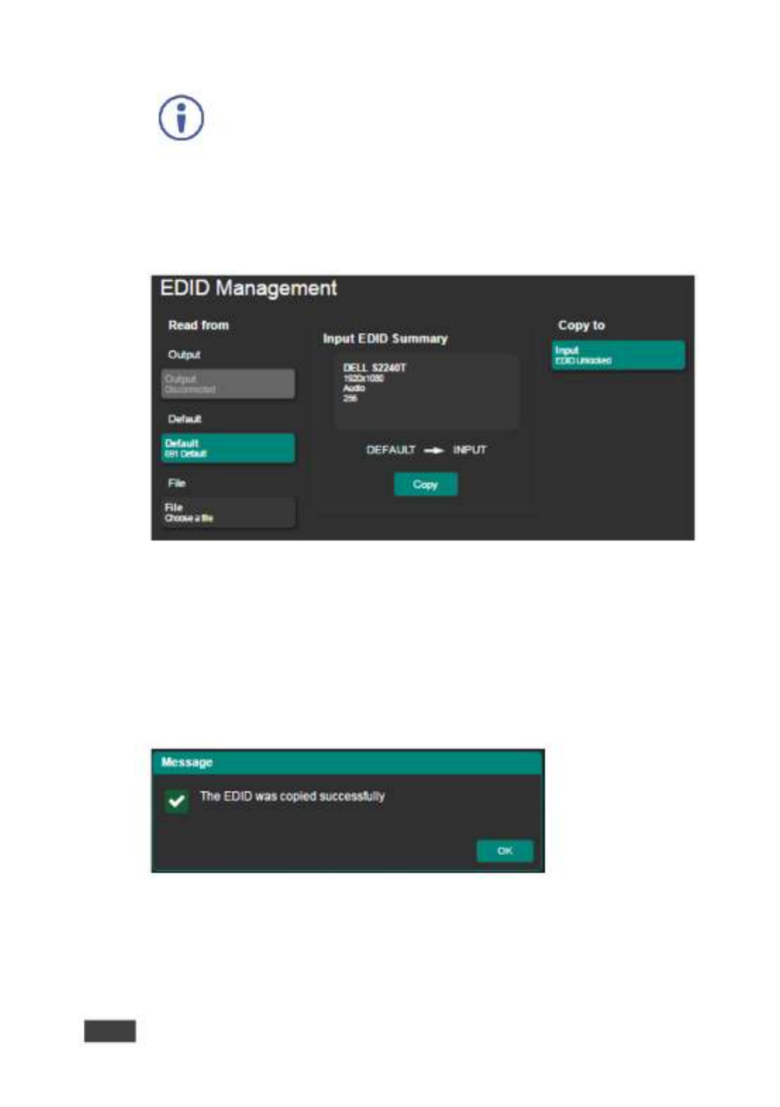
1. In the Navigation pane, click . The EDID Management EDID Management
page appears:
Figure : The EDID Management Page 20
2. Select one of the following EDID sources: the output, the default, or 691
click . Choose a le
3. Click and wait for the device to complete the process. Copy
The “EDID was copied successfully” message is displayed and the EDID
data is copied to the input.
Figure The EDID Message 21:
4. Click . OK

691 - Using the Embedded Web Pages
35
The Input EDID Summary Information area displays the current selection of EDID
source, video resolution, audio availability, and so on.
5. Set DIP-switch 3 to ON (down).
The new EDID is saved and locked.
8.5 Authentication Page
The Authentication page lets you assign or change logon authentication details.
By-default User and Password are both Admin.
To set the authentication details:
1. In the Navigation pane, click . The Authentication page Authentication
appears:
Figure The Authentication Page 22:
2. Set the authentication:
▪ Activate Security: enable or disable the security settings. When
enabled, the valid username (Admin, by default) and password (Admin,
by default) must be provided to allow Web page access.
▪ Change Password: enter the current password, enter the new
password and then retype the new password and click . Change
If the Authentication page is left open for more than ve minutes
additional windows may open. After entering your logon credentials,
close the other windows.

36
691 - Using the Embedded Web Pages
8.6 Viewing the About Page
The About page lets you view the Web page version and Kramer Electronics 691
Ltd details.
Figure : The About Page 23

691 - Firmware Upgrade
37
9 Firmware Upgrade
You can upgrade the via the Kramer tool. 691 K-UPLOAD
The latest rmware version and the latest version of and K-UPLOAD
installation instructions can be downloaded from Kramer Web site at
www.kramerav.com/downloads/691.

38
691 - Technical Specications
10 Technical Specications
Inputs
1 HDMI
On a female HDMI connector
1 Stereo Analog Unbalanced
Audio
2Vrms / 10kΩ on a 3.5mm mini
jack
Outputs
1 Fiber Optic
O 2 LC connectors n
Ports
1 IR
On a 3.5mm mini jack for IR link
extension
1 USB
On a female USB- connector B
for USB link extension
1 RS- 232
On a 3-pin terminal block for
serial link extension
1 RS- 232
On a 3-pin terminal block for
device control
1 100BaseT Ethernet
On an RJ-45 female connector
for device control and LAN
extension
Extension Line
Compliance
HDBaseT 2.0
Optical Fiber
Multi-mode (MM) or single-
mode (SM)
Fiber Line
2 simplex strands
Optical Module
10Gbps SFP+ IEEE 802.3ae
compliant
Multi-mode Line
Compliance
G.651.1 OFNR ber
Nominal Peak Wavelength
850nm
Max Data Rate
10.2Gbps
Typical Optical Transmission
Power
-2.5dBm
Typical Optical Maximum Loss
B udget
8.6dB
Max Reach over OM3 MM Fiber
3km (1.86 miles)
Single-mode
Line
Compliance
G.652D OFNR ber
Nominal Peak Wavelength
1310nm
Max Data Rate
10.2Gbps
Typical Optical Transmission
Power
-2.5dBm
Typical Optical Maximum Loss
B udget
11.9dB
Max Reach over O S Fiber S1 M
33km (20.5 miles)

691 - Technical Specications
39
Video
Max Bandwidth
10.2Gbps (3.4Gbps per graphic
channel)
Max Resolution
4K UHD @60Hz (4:2:0) 24bpp
resolution
Content Protection
HDCP 1.4
HDMI Support
Supports deep color,
x.v.Color™, lip sync, HDMI
uncompressed audio channels,
Dolby TrueHD, DTS HD, 2K, –
4K, and 3D as specified in
HDMI 2.0
Analog Audio
Max Vrms Level
1
THD + NOISE
0.03% @1kHz at nominal level
Extended USB
Host Compliance
1.1 and 2.0
Max Extended Line Rate
Bandwidth
127Mbps (out of max 480 USB)
Max Devices
7
Max Hubs
2
Max Ports per Hub
8
Extended
Ethernet
Max Transmission Bandwidth
100Mbps
Extended
RS- 232
Baud Rate
300 to 115200
Control RS- 232
Baud Rate
115200
Supported PC
Web Browsers
Windows 7 and Higher
Internet Explorer (32/64 bit)
version 10
Firefox version 30
Chrome version 35
MAC
Chrome version 35
Firefox version 30
Safari version 7
Minimum Browser Window Size
1024 x 768
Power
Consumption
12V DC, 1300mA
Source
12V DC, 2A
Cooling
Convection Ventilation
Environmental
Conditions
Operating Temperature
0° to +40°C (32° to 104°F)
Storage Temperature
-40° to +70°C (-40° to 158°F)
Humidity
10% to 90%, RHL non-
condensing
Regulatory
Compliance
Safety
CE, UL
Environmental
RoHs, WEEE
Enclosure
Size
Half 19” 1U
Type
Aluminum
General
Net Dimensions (W, D, H)
21.46cm x 16.3 cm x 4.36cm
(8.45" x 6.42" x 1.7")
Shipping Dimensions (W, D, H)
35.1cm x 21.2cm x 7.2cm
(13.82" x 8.35" x 2.8")
Net Weight
0.95 kg (2.1lbs)
Shipping Weight
1.45 kg (3.2lbs) approx.

40
691 - Technical Specications
Accessories
Included
Power adapter (12V, 2A),
OSP-MM1 optical transceiver
Optional
For optimum range and
performance use the
recommended USB, Ethernet,
serial and IR Kramer cables
available at
www.kramerav.com/product/691
Specications are subject to change without notice at www.kramerav.com
10.1 Default Communication Parameters
RS-232
Baud Rate:
115,200
Data Bits:
8
Stop Bits:
1
Parity:
None
Command Format:
ASCII
Example (get device model
name):
#model?<cr>
Ethernet
IP Address:
192.168.1.39
Subnet mask:
255.255.0.0
Default gateway:
192.168.0.1
UDP Port:
50000
TCP Port:
5000
Full Factory Reset
Rear panel button:
Press and hold for 5 seconds to reset the device to factory
default settings.
P3k command:
#factory<cr>
Embedded Web pages:
Select Device Settings page and click Factory reset
10.2 Default Parameters
Parameter
Value
Name
KRAMER_
Model
691
Audio delay input switching on new signal
0 seconds
Audio delay input switching on signal loss (leave
5V on)
5 seconds
Audio delay input switching on cable unplug
0 seconds
Video delay power o 5V on signal loss
15 minutes
HDCP
Follow output
Web Logon credentials
Name: Admin; Password: Admin

691 - Technical Specications
41
10.3 Default EDID
Monitor
Model name............... 691
Manufacturer............. KMR
Plug and Play ID......... KMR1200
Serial number............ n/a
Manufacture date......... 2015, ISO week 255
Filter driver............ None
-------------------------
EDID revision............ 1.3
Input signal type........ Digital
Color bit depth.......... Undened
Display type............. RGB color
Screen size.............. 520 x 320 mm (24.0 in)
Power management......... Standby, Suspend, Active o/sleep
Extension blocs.......... 1 (CEA-EXT)
-------------------------
DDC/CI................... n/a
Color characteristics
Default color space...... Non-sRGB
Display gamma............ 2.20
Red chromaticity......... Rx 0.674 - Ry 0.319
Green chromaticity....... Gx 0.188 - Gy 0.706
Blue chromaticity........ Bx 0.148 - By 0.064
White point (default).... Wx 0.313 - Wy 0.329
Additional descriptors... None
Timing characteristics
Horizontal scan range.... 30-83kHz
Vertical scan range...... 56-76Hz
Video bandwidth.......... 170MHz
CVT standard............. Not supported
GTF standard............. Not supported
Additional descriptors... None
Preferred timing......... Yes
Native/preferred timing.. 1280x720p at 60Hz (16:10)
Modeline............... "1280x720" 74.250 1280 1390 1430 1650 720 725 730 750 +hsync +vsync
Standard timings supported
720 x 400p at 70Hz - IBM VGA
720 x 400p at 88Hz - IBM XGA2
640 x 480p at 60Hz - IBM VGA
640 x 480p at 67Hz - Apple Mac II
640 x 480p at 72Hz - VESA
640 x 480p at 75Hz - VESA
800 x 600p at 56Hz - VESA
800 x 600p at 60Hz - VESA
800 x 600p at 72Hz - VESA
800 x 600p at 75Hz - VESA
832 x 624p at 75Hz - Apple Mac II
1024 x 768i at 87Hz - IBM
1024 x 768p at 60Hz - VESA
1024 x 768p at 70Hz - VESA
1024 x 768p at 75Hz - VESA
1280 x 1024p at 75Hz - VESA
1152 x 870p at 75Hz - Apple Mac II
1280 x 1024p at 75Hz - VESA STD
1280 x 1024p at 85Hz - VESA STD
1600 x 1200p at 60Hz - VESA STD
1024 x 768p at 85Hz - VESA STD
800 x 600p at 85Hz - VESA STD
640 x 480p at 85Hz - VESA STD
1152 x 864p at 70Hz - VESA STD
1280 x 960p at 60Hz - VESA STD
EIA/CEA-861 Information
Revision number.......... 3
IT underscan............. Supported
Basic audio.............. Supported

42
691 - Technical Specications
YCbCr 4:4:4.............. Supported
YCbCr 4:2:2.............. Supported
Native formats........... 1
Detailed timing #1....... 1920x1080p at 60Hz (16:10)
Modeline............... "1920x1080" 148.500 1920 2008 2052 2200 1080 1084 1089 1125 +hsync +vsync
Detailed timing #2....... 1920x1080i at 60Hz (16:10)
Modeline............... "1920x1080" 74.250 1920 2008 2052 2200 1080 1084 1094 1124 interlace +hsync
+vsync
Detailed timing #3....... 1280x720p at 60Hz (16:10)
Modeline............... "1280x720" 74.250 1280 1390 1430 1650 720 725 730 750 +hsync +vsync
Detailed timing #4....... 720x480p at 60Hz (16:10)
Modeline............... "720x480" 27.000 720 736 798 858 480 489 495 525 -hsync -vsync
CE audio data (formats supported)
LPCM 2-channel, 16/20/24 bit depths at 32/44/48 kHz
CE video identiers (VICs) - timing/formats supported
1920 x 1080p at 60Hz - HDTV (16:9, 1:1)
1920 x 1080i at 60Hz - HDTV (16:9, 1:1)
1280 x 720p at 60Hz - HDTV (16:9, 1:1) [Native]
720 x 480p at 60Hz - EDTV (16:9, 32:27)
720 x 480p at 60Hz - EDTV (4:3, 8:9)
720 x 480i at 60Hz - Doublescan (16:9, 32:27)
720 x 576i at 50Hz - Doublescan (16:9, 64:45)
640 x 480p at 60Hz - Default (4:3, 1:1)
NB: NTSC refresh rate = (Hz*1000)/1001
CE vendor specic data (VSDB)
IEEE registration number. 0x000C03
CEC physical address..... 1.0.0.0
Maximum TMDS clock....... 165MHz
CE speaker allocation data
Channel conguration.... 2.0
Front left/right......... Yes
Front LFE................ No
Front center............. No
Rear left/right.......... No
Rear center.............. No
Front left/right center.. No
Rear left/right center... No
Rear LFE................. No
Report information
Date generated........... 23/07/2015
Software revision........ 2.60.0.972
Data source.............. File
Operating system......... 6.1.7601.2.Service Pack 1
Raw data
00,FF,FF,FF,FF,FF,FF,00,2D,B2,00,12,00,00,00,00,FF,19,01,03,80,34,20,78,EA,B3,25,AC,51,30,B4,26,
10,50,54,FF,FF,80,81,8F,81,99,A9,40,61,59,45,59,31,59,71,4A,81,40,01,1D,00,72,51,D0,1E,20,6E,28,
55,00,07,44,21,00,00,1E,00,00,00,FD,00,38,4C,1E,53,11,00,0A,20,20,20,20,20,20,00,00,00,FC,00,54,
50,2D,35,39,30,52,58,52,20,20,20,20,00,00,00,00,00,00,00,00,00,00,00,00,00,00,00,00,00,00,01,28,
02,03,1B,F1,23,09,07,07,48,10,05,84,03,02,07,16,01,65,03,0C,00,10,00,83,01,00,00,02,3A,80,18,71,
38,2D,40,58,2C,45,00,07,44,21,00,00,1E,01,1D,80,18,71,1C,16,20,58,2C,25,00,07,44,21,00,00,9E,01,
1D,00,72,51,D0,1E,20,6E,28,55,00,07,44,21,00,00,1E,8C,0A,D0,8A,20,E0,2D,10,10,3E,96,00,07,44,21,
00,00,18,00,00,00,00,00,00,00,00,00,00,00,00,00,00,00,00,00,00,00,00,00,00,00,00,00,00,00,00,47

691 - Protocol 3000
43
11 Protocol 3000
The HDBT 2.0 Optical Transmitter can be operated using the Kramer 691
Protocol 3000 serial commands. The command framing varies according to how
you interface with the . For example, a basic video input switching command
691
that routes a layer 1 video signal to HDMI out 1 from HDMI input 2
( ), is entered as follows: ROUTE 1,1,2
• Terminal communication software, such as Hercules:
The framing of the command varies according to the terminal
communication software.
• K-Touch Builder (Kramer software):

44
691 - Protocol 3000
• K-Cong (Kramer conguration software):
All the examples provided in this section are based on using the
K-Cong software.
You can enter commands directly using terminal communication software (e.g.,
Hercules) by connecting a PC to the serial or Ethernet port on the . To enter 691
CR LF press the Enter key ( is also sent but is ignored by the command parser).
Commands sent from various non-Kramer controllers (e.g., Crestron) may require
special coding for some characters (such as, ). For more information, refer to /X##
your controller’s documentation.
For more information about:
• Using Protocol 3000 commands, se e Section 11.1
• General syntax used for Protocol 3000 commands, see Section 11.2
• Protocol 3000 commands available for the , see 691 Section 11.3
11.1 Understanding Protocol 3000
Protocol 3000 commands are structured according to the following:
• Command –A sequence of ASCII letters ( and ). A command A-Z, a-z -
and its parameters must be separated by at least one space.
• Parameters –A sequence of alphanumeric ASCII characters (0-9, A-Z,
a-z and some special characters for specic commands). Parameters are
separated by commas.
• Message string –Every command entered as part of a message string
begins with a message starting character and ends with a message closing
character.
A string can contain more than one command. Commands are
separated by a pipe ( ) character. |

691 - Protocol 3000
45
The maximum string length is 64 characters.
• Message starting character:
▪ # For host command/query –
▪ ~ For device respon –se
• Device address K-NET Device ID followed by (optional, K-NET only) –@
• Query sign follows some commands to dene a query request –?
• Message closing character:
▪ CR Carriage return for host messages (ASCII 13) –
▪ CR LF Carriage return for device messages (ASCII 13) and line-feed –
(ASCII 10)
• Command chain separator character –Multiple commands can be
chained in the same string. Each command is delimited by a pipe character
( ). When chaining commands, enter the message starting character and |
the message closing character only at the beginning and end of the string.
Spaces between parameters or command terms are ignored.
Commands in the string do not execute until the closing character is
entered. A separate response is sent for every command in the
chain.
Produktspecifikationer
| Varumärke: | Kramer |
| Kategori: | AV extender |
| Modell: | 691 |
Behöver du hjälp?
Om du behöver hjälp med Kramer 691 ställ en fråga nedan och andra användare kommer att svara dig
AV extender Kramer Manualer

2 Februari 2025
20 December 2024
20 December 2024
20 December 2024
20 December 2024
20 December 2024
20 December 2024
20 December 2024
20 December 2024
20 December 2024
AV extender Manualer
- AV extender Philips
- AV extender Ag Neovo
- AV extender Allnet
- AV extender Act
- AV extender Nedis
- AV extender Pyle
- AV extender Eminent
- AV extender Renkforce
- AV extender Manhattan
- AV extender Black Box
- AV extender KEF
- AV extender Tripp Lite
- AV extender Vision
- AV extender Roland
- AV extender DataVideo
- AV extender Techly
- AV extender Bogen
- AV extender Matrox
- AV extender Steren
- AV extender Teufel
- AV extender AJA
- AV extender Digitus
- AV extender Belkin
- AV extender Peerless-AV
- AV extender LevelOne
- AV extender InFocus
- AV extender Planet
- AV extender Konig
- AV extender D-Link
- AV extender One For All
- AV extender Marmitek
- AV extender Marshall Electronics
- AV extender Genexis
- AV extender ATen
- AV extender Kindermann
- AV extender Gefen
- AV extender Vivotek
- AV extender Wentronic
- AV extender Peerless
- AV extender Dynaudio
- AV extender Adder
- AV extender Kopul
- AV extender Monoprice
- AV extender MIPRO
- AV extender Crestron
- AV extender I3-Technologies
- AV extender Monacor
- AV extender Logilink
- AV extender Smart-AVI
- AV extender StarTech.com
- AV extender SIIG
- AV extender Polycom
- AV extender Advantech
- AV extender IOGEAR
- AV extender Micro Connect
- AV extender Extron
- AV extender KanexPro
- AV extender Intelix
- AV extender ASSMANN Electronic
- AV extender Blustream
- AV extender Avocent
- AV extender Rose
- AV extender Intellinet
- AV extender Ebode
- AV extender Speaka
- AV extender Accell
- AV extender Schwaiger
- AV extender Ecler
- AV extender Rose Electronics
- AV extender Epcom
- AV extender CYP
- AV extender TV One
- AV extender SmartAVI
- AV extender IMG Stage Line
- AV extender Oehlbach
- AV extender Lindy
- AV extender Atlona
- AV extender AVMATRIX
- AV extender HELGI
- AV extender Liberty
- AV extender PureTools
- AV extender Enson
- AV extender Lightware
- AV extender Vivolink
- AV extender Approx
- AV extender Alfatron
- AV extender SWIT
- AV extender Hall Research
- AV extender AMX
- AV extender WyreStorm
- AV extender Rocstor
- AV extender Apantac
- AV extender MuxLab
- AV extender Seco-Larm
- AV extender ConnectPro
- AV extender Kanex
- AV extender TechLogix Networx
- AV extender C2G
- AV extender SEADA
- AV extender Comprehensive
- AV extender Sescom
- AV extender Analog Way
- AV extender PureLink
- AV extender DVDO
- AV extender Camplex
Nyaste AV extender Manualer
1 April 2025
1 April 2025
1 April 2025
1 April 2025
1 April 2025
26 Februari 2025
25 Februari 2025
20 Februari 2025
20 Februari 2025
7 Februari 2025