MSI B450 Tomahawk Max Bruksanvisning
Läs nedan 📖 manual på svenska för MSI B450 Tomahawk Max (101 sidor) i kategorin moderkort. Denna guide var användbar för 3 personer och betygsatt med 4.5 stjärnor i genomsnitt av 2 användare
Sida 1/101

1
Quick Start
DDR4 Memory
Graphics Card
SATA Hard Disk Drive
SATA DVD Drive
Phillips Screwdriver
Chassis
Power Supply Unit
A Package of Screws
Thermal Paste
Quick Start
Thank you for purchasing the MSI® B450 TOMAHAWK motherboard. This Quick Start
section provides demonstration diagrams about how to install your computer. Some
of the installations also provide video demonstrations. Please link to the URL to watch
it with the web browser on your phone or tablet. You may have even link to the URL by
scanning the QR code
Preparing Tools and Components
AMD® AM4 CPU
CPU Fan

2Quick Start
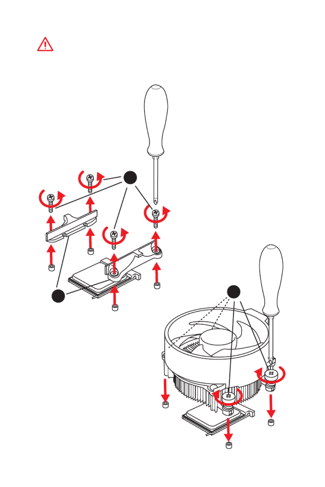
Installing a Processor
1
2
3
6
4
5
7
8
9
https://youtu.be/Xv89nhFk1vc
3
Quick Start
1
23
Important
If you are installing the screw-type CPU heatsink, please follow the figure below to
remove the retention module first and then install the heatsink.

4Quick Start
Installing DDR4 memory
http://youtu.be/T03aDrJPyQs
DIMMB2 DIMMB2
DIMMB1
DIMMA2 DIMMA2 DIMMA2
DIMMA1
1
1
2
2
3
3
5
Quick Start
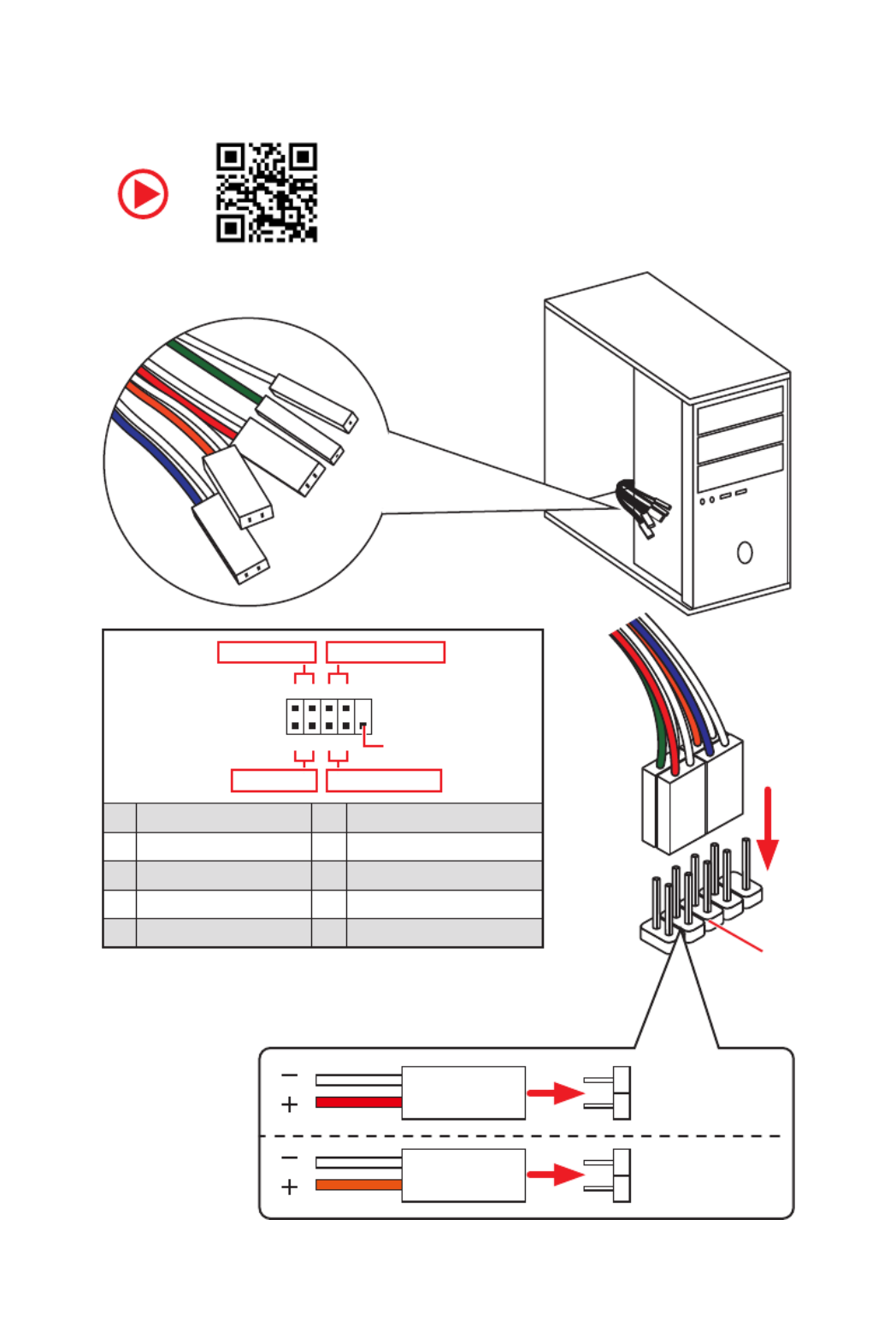
Connecting the Front Panel Header
http://youtu.be/DPELIdVNZUI
RESET SW
POWER SW
POWER LED+
POWER LED-
HDD LED
HDD LED
RESET SW
JFP1
HDD LED HDD LED -
HDD LED +
POWER LED -
POWER LED +
POWER LED
1
2 10
9
++
+- --
-
+
Power LED
HDD LED Reset Switch
Reserved
Power Switch
JFP1
1 HDD LED + 2 Power LED +
3 HDD LED - 4 Power LED -
5 Reset Switch 6 Power Switch
7 Reset Switch 8 Power Switch
9 Reserved 10 No Pin

6Quick Start
BAT 1
Installing the Motherboard
1
2

7
Quick Start
Installing SATA Drives
http://youtu.be/RZsMpqxythc
1
23
4
5

8Quick Start
1
Installing a Graphics Card
http://youtu.be/mG0GZpr9w_A
2
3
4
5
6

9
Quick Start
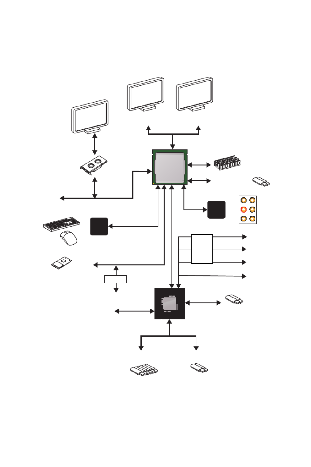
Connecting Peripheral Devices
Ryzen™ with Radeon Vega
Graphics Processors

10 Quick Start
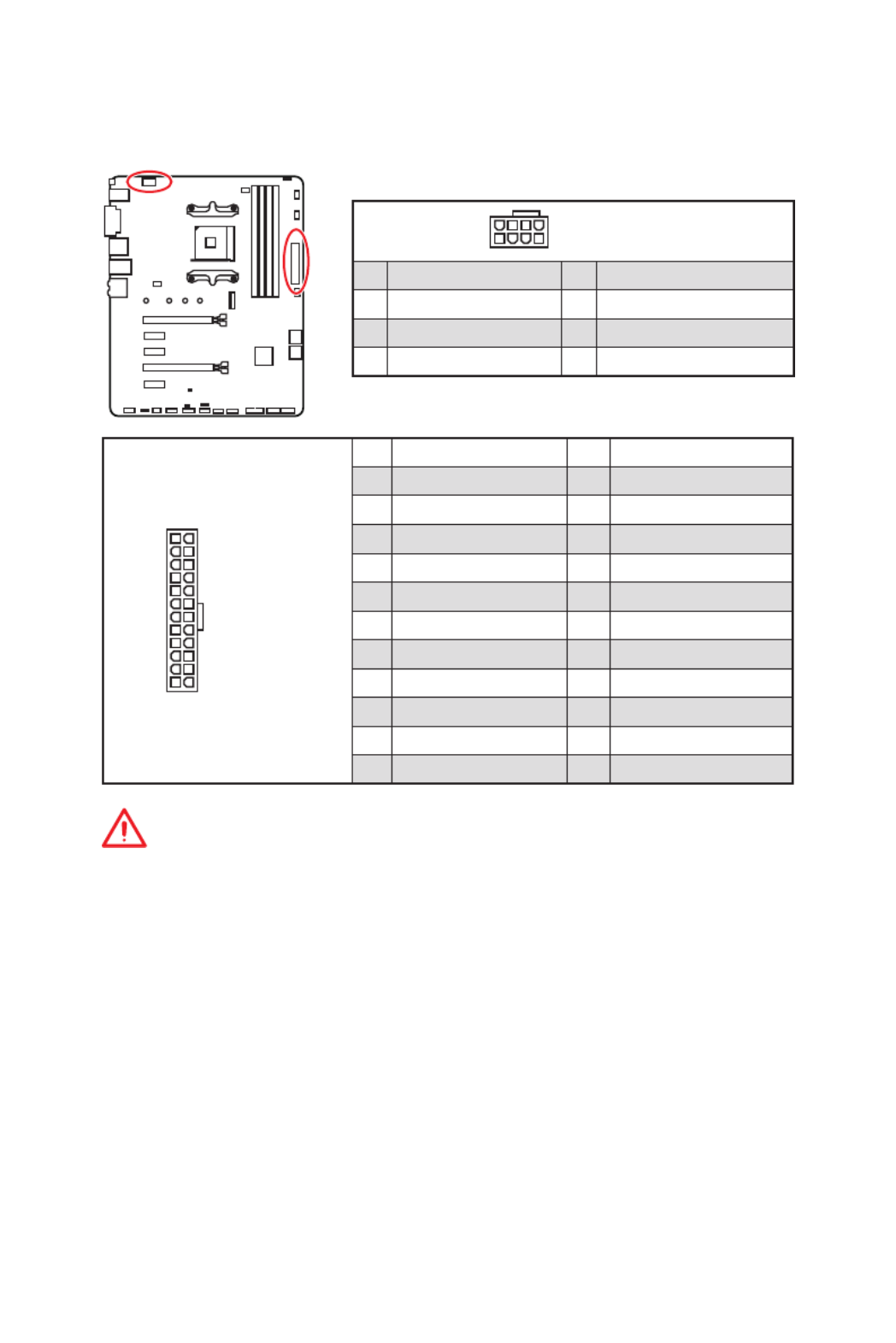
Connecting the Power Connectors
http://youtu.be/gkDYyR_83I4
ATX_PWR1 CPU_PWR1

11
Quick Start
Power On
1
4
2
3

12 Contents
Contents
Quick Start ............................................................................................................. 1
Preparing Tools and Components 1 ..........................................................................
Installing a Processor 2 .............................................................................................
Installing DDR4 memory 4 ........................................................................................
Connecting the Front Panel Header 5 .......................................................................
Installing the Motherboard 6 .....................................................................................
Installing SATA Drives............................................................................................. 7
Installing a Graphics Card 8 ......................................................................................
Connecting Peripheral Devices 9 ..............................................................................
Connecting the Power Connectors 10 .......................................................................
Power On............................................................................................................... 11
Safety Information ............................................................................................... 15
Specifications 16 .......................................................................................................
Package contents ................................................................................................ 21
Block Diagram .................................................................................................... 22
Rear I/O Panel ..................................................................................................... 23
LAN Port LED Status Table................................................................................... 23
Audio Ports Configuration 23 ....................................................................................
Realtek Audio Console 24 .........................................................................................
Overview of Components .................................................................................... 26
Processor Socket 28 ..................................................................................................
DIMM Slots 29 ............................................................................................................
PCI_E1~5: PCIe Expansion Slots 30 ..........................................................................
M2_1: M.2 Slot (Key M) 31 .........................................................................................
SATA1~6: SATA 6Gb/s Connectors 32 .......................................................................
JFP1, JFP2: Front Panel Connectors 32 ...................................................................
CPU_PWR1, ATX_PWR1: Power Connectors 33 .......................................................
JUSB1~2: USB 2.0 Connectors 34 .............................................................................
JUSB3: USB 3.1 Gen1 Connector 34 .........................................................................
CPU_FAN1, PUMP_FAN1, SYS_FAN1~4: Fan Connectors 35 ...................................
JAUD1: Front Audio Connector 35 ............................................................................
JCI1: Chassis Intrusion Connector 36 .......................................................................
JCOM1: Serial Port Connector 36 .............................................................................
JTPM1: TPM Module Connector 37 ...........................................................................
JBAT1: Clear CMOS (Reset BIOS) Jumper 37 ...........................................................

14 Contents
Change the Controller Options 93 .............................................................................
Booting the system from an array 93 ........................................................................
Pausing the boot sequence for warning messages 93 .............................................
Change the Staggered Spinup Count 94 ...................................................................
Using UEFI to create a 2.2TB RAID 95 ......................................................................
Installing RAID Driver 96 ...........................................................................................
Troubleshooting .................................................................................................. 97
Regulatory Notices .............................................................................................. 98

15
Safety Information
Safety Information
yThe components included in this package are prone to damage from electrostatic
discharge (ESD). Please adhere to the following instructions to ensure successful
computer assembly.
yEnsure that all components are securely connected. Loose connections may cause
the computer to not recognize a component or fail to start.
yHold the motherboard by the edges to avoid touching sensitive components.
yIt is recommended to wear an electrostatic discharge (ESD) wrist strap when
handling the motherboard to prevent electrostatic damage. If an ESD wrist strap is
not available, discharge yourself of static electricity by touching another metal object
before handling the motherboard.
yStore the motherboard in an electrostatic shielding container or on an anti-static pad
whenever the motherboard is not installed.
yBefore turning on the computer, ensure that there are no loose screws or metal
components on the motherboard or anywhere within the computer case.
yDo not boot the computer before installation is completed. This could cause
permanent damage to the components as well as injury to the user.
yIf you need help during any installation step, please consult a certified computer
technician.
yAlways turn off the power supply and unplug the power cord from the power outlet
before installing or removing any computer component.
yKeep this user guide for future reference.
yKeep this motherboard away from humidity.
yMake sure that your electrical outlet provides the same voltage as is indicated on the
PSU, before connecting the PSU to the electrical outlet.
yPlace the power cord such a way that people can not step on it. Do not place anything
over the power cord.
yAll cautions and warnings on the motherboard should be noted.
yIf any of the following situations arises, get the motherboard checked by service
personnel:
Liquid has penetrated into the computer.
The motherboard has been exposed to moisture.
The motherboard does not work well or you can not get it work according to user
guide.
The motherboard has been dropped and damaged.
The motherboard has obvious sign of breakage.
yDo not leave this motherboard in an environment above 60 C (140 F), it may damage ° °
the motherboard.

16 Specifications
Specifications
CPU Support AMD® Ryzen™ 1st and 2nd Generation/ Ryzen™ with
Radeon™ Vega Graphics Processors for Socket AM4
Chipset AMD® B450 Chipset
Memory
y4x DDR4 memory slots, support up to 64GB*
Supports 1866/ 2133/ 2400/ 2667Mhz (by JEDEC)
Supports 2667/ 2800/ 2933/ 3000/ 3066/ 3200/ 3466 MHz
(by A-XMP OC MODE)
yDual channel memory architecture
ySupports non-ECC UDIMM memory
ySupports ECC UDIMM memory (non-ECC mode)
* Please refer www.msi.com for more information on compatible memory.
Expansion Slots
y1x PCIe 3.0 x16 slot (PCI_E1)
Supports x16 speed with AMD® Ryzen™ 1st and 2nd
Generation processors
Supports p16-x8 speed with AMD
® Ryzen™ with Radeon
Vega Graphics processors
y1x PCIe 2.0 x16 slot (PCI_E4, supports p16-x4 mode)*
y3x PCIe 2.0 p16-x1 slots*
* PCI_E4 will run p16-x2 speed when installing devices in PCI_E2/ PCI_E3 slot.
Onboard Graphics
y1x DVI-D port, support a maximum resolution of 1920x1200
@60Hz*
y1x HDMI™ 1.4 port, supports a maximum resolution of
4096x2160@30Hz, 2560x1600@60Hz*
* Only support when using AMD
® Ryzen™ with Radeon Vega Graphics Processors
* Maximum shared memory of 2048 MB
Multi-GPU ySupports 2-Way AMD®
CrossFire™ Technology
Continued on next page

17
Specifications
Continued from previous page
Storage
AMD® CPU
y2x SATA 6Gb/s ports*
y1x M.2 slot (Key M)*
Supports PCIe 3.0 p17-x4 and SATA 6Gb/s 2242/ 2260 /2280/
22110 storage devices
AMD® B450 Chipset
y4x SATA 6Gb/s ports
* SATA5 and SATA6 ports will be unavailable when installing a M.2 device in M.2
slot.
RAID
AMD® B450 Chipset
ySupports RAID 0, RAID1 and RAID 10 for SATA storage
devices
USB
yAMD® B450 Chipset
1x USB 3.1 Gen2 (SuperSpeed USB 10Gbps) Type-C port
on the back panel
1x USB 3.1 Gen2 (SuperSpeed USB 10Gbps) Type-A port
on the back panel
2x USB 3.1 Gen1 (SuperSpeed USB) ports available
through the internal USB 3.1 Gen1 connector
6x USB 2.0 (High-speed USB) ports (2 Type-A ports on
the back panel, 4 ports available through the internal
USB 2.0 connectors)
yAMD® CPU
2x USB 3.1 Gen1 (SuperSpeed USB) Type-A ports on the
back panel
LAN y1x Realtek® 8111H Gigabit LAN controller
Audio yRealtek® ALC892 Codec
y7.1-Channel High Definition Audio
Continued on next page

18 Specifications
Continued from previous page
Back Panel
Connectors
y1x BIOS FLASHBACK+ button
y1x PS/2 keyboard/ mouse combo port
y2x USB 2.0 Type-A ports
y1x DVI-D port
y1x HDMI™ port
y2x USB 3.1 Gen1 Type-A ports
y1x LAN (RJ45) port
y1x USB 3.1 Gen2 Type-A port
y1x USB 3.1 Gen2 Type-C port
y6x audio jacks
Internal Connectors
y1x 24-pin ATX main power connector
y1x 8-pin ATX 12V power connector
y6x SATA 6Gb/s connectors
y2x USB 2.0 connectors (support additional 4 USB 2.0 ports)
y1x USB 3.1 Gen1 connectors (support additional 2 USB 3.1
Gen1 ports)
y1x 4-pin CPU fan connector
y1x 4-pin water-pump-fan connector
y4x 4-pin system fan connectors
y1x TPM module connector
y1x Front panel audio connector
y2x System panel connectors
y1x Chassis Intrusion connector
y1x Serial Port connector
y1x Clear CMOS jumper
y2x 5050 RGB LED strip 12V connectors
I/O Controller NUVOTON NCT6797 Controller Chip
Hardware Monitor
yCPU/System temperature detection
yCPU/System fan speed detection
yCPU/System fan speed control
Continued on next page

19
Specifications
Continued from previous page
Form Factor yATX Form Factor
y12 in. x 9.6 in. (30.5 cm x 24.4 cm)
BIOS Features
y1x 128 Mb flash
yUEFI AMI BIOS
yACPI 6.1, SM BIOS 2.8
yMulti-language
Software
yDrivers
yAPP MANAGER
ySUPER CHARGER
yCOMMAND CENTER
yLIVE UPDATE 6
ySMART TOOL
yRAMDISK
yX-BOOST
yGAMING APP
yMYSTIC LIGHT
yOpen Broadcaster Software (OBS)
yCPU-Z MSI GAMING
yNorton™ Internet Security Solution
yGoogle Chrome™, Google Toolbar, Google Drive
Special Features
yAudio
Audio Boost
yStorage
Turbo M.2
StoreMI
yFan
Pump Fan
GAMING Fan Control
Continued on next page

20 Specifications
Continued from previous page
Special Features
yLED
Mystic Light
Mystic Light Extension (RGB)
Mystic light SYNC
EZ DEBUG LED
yProtection
PCIe Steel Armor
PCIe Steel Slot
yPerformance
Multi GPU-CrossFire Technology
DDR4 Boost
GAME Boost
USB with type A+C
AMD Turbo USB 3.1 Gen 2
CORE Boost
yVR
VR Ready
yGamer Experience
GAMING HOTKEY
GAMING MOUSE Control
yBIOS
Click BIOS 5
AMD FreeSync™ Ready
AMD Precision Boost OverDrive™
yCertification
GAMING Certified

21
Package contents
Package contents
Please check the contents of your motherboard package. It should contain:
yMotherboard
yDriver DVD
yUser Manual
yQuick Installation Guide
yI/O Shielding
ySATA 6G Cable p21-x2
yCase Badge
yVIP card
yM.2 Screw x1
Important
If any of the above items are damaged or missing, please contact your retailer.
22 Block Diagram
Block Diagram
2 x USB 3.1 Gen2
2 Channel DDR4 Memory
2 x USB 3.1 Gen1
1 x M.2
6 x USB 2.0
PCI Express Bus
PS/2 Mouse / Keyboard
Audio Jacks
CHIPSET
CPU
NV6797
Super I/O
Realtek
ALC892
PCI Express Bus
HDMI DVI-D
SwitchSwitch
PCIe p22-x1
2x SATA 6Gb/s
4x SATA 6Gb/s
PCIe p22-x1
PCIe p22-x1
PCIe x4
2x USB 3.1 Gen1
Switch

23
Rear I/O Panel
USB 3.1 Gen2
Type-C
Link/ Activity LED
Status Description
Off No link
Yellow Linked
Blinking Data activity
Speed LED
Status Description
Off 10 Mbps connection
Green 100 Mbps connection
Orange 1 Gbps connection
LAN Port LED Status Table
Audio Ports Configuration
Audio Ports
Channel
2468
Line-In
Line-Out/ Front Speaker Out ●●●●
Rear Speaker Out ●●●
Center/ Subwoofer Out ● ●
Side Speaker Out ●
Mic In
( : connected, : empty)●Blank
Rear I/O Panel
PS/2 LAN
USB 2.0 Type-A
Audio Ports
DVI-D
USB 3.1 Gen1 Type-A
USB 3.1 Gen2
Type-A
BIOS FLASHBACK+
button
yBIOS FLASHBACK+ port/ button - Please refer to page 41 for Updating BIOS with
BIOS FLASHBACK+.
BIOS
FLASHBACK+
Port

24 Rear I/O Panel
Realtek Audio Console
After Realtek Audio Console is installed. You can use it to change sound settings to get
better sound experience.
yDevice Selection - allows you to select a audio output source to change the related
options. The sign indicates the devices as default.check
yApplication Enhancement - the array of options will provide you a complete guidance
of anticipated sound effect for both output and input device.
yMain Volume - controls the volume or balance the right/left side of the speakers that
you plugged in front or rear panel by adjust the bar.
yJack Status - depicts all render and capture devices currently connected with your
computer.
Auto popup dialog
When you plug into a device at an audio jack, a dialogue window will pop up asking you
which device is current connected.
Each jack corresponds to its default setting as shown on the next page.
Jack Status
Device
Selection
Main Volume
Application Enhancement
Important
The pictures above for reference only and may vary from the product you purchased.

25
Rear I/O Panel
Audio jacks to headphone and microphone diagram
Audio jacks to stereo speakers diagram
Audio jacks to 7.1-channel speakers diagram
AUDIO INPUT
Rear Front
Side Center/
Subwoofer
AUDIO INPUT

26 Overview of Components
BA T 1
Overview of Components
JFP2
JFP1
SATA 5 6▼ ▲
SATA 3 4▼ ▲
CPU_FAN1
SYS_FAN1
PUMP_FAN1
JRGB2
PCI_E1
PCI_E2
PCI_E3
PCI_E4
PCI_E5
JBAT1
JAUD1
JTPM1
Processor
Socket
CPU_PWR1
DIMMA1
SYS_FAN4
M2_1
DIMMA2
DIMMB1
DIMMB2
JUSB3
SATA2
JUSB2
JUSB1
SATA1
JRGB1
SYS_FAN2
JCOM1
ATX_PWR1
SYS_FAN3
JCI1

27
Overview of Components
Component Contents
Port Name Port Type Page
CPU_FAN1, PUMP_FAN1, SYS_FAN1~4 Fan Connectors 35
CPU_PWR1, ATX_PWR1 Power Connectors 33
DIMMA1, DIMMA2, DIMMB1, DIMMB2 DIMM Slots 29
JAUD1 Front Audio Connector 35
JBAT1 Clear CMOS Jumper 37
JCI1 Chassis Intrusion Connector 36
JCOM1 Serial Port Connector 36
JFP1, JFP2 Front Panel Connectors 32
JRGB1~2 RGB LED connectors 38
JTPM1 TPM Module Connector 37
JUSB1~2 USB 2.0 Connectors 34
JUSB3 USB 3.1 Gen1 Connector 34
M2_1 M.2 Slot (Key M) 31
PCI_E1~5 PCIe Expansion Slots 30
Processor Socket AM4 socket 28
SATA1~6 SATA 6Gb/s Connectors 32

28 Overview of Components
Processor Socket
Important
y
When changing the processor, the system configuration could be cleared and reset
BIOS to default values, due to the AM4 processor’s architecture.
y
Always unplug the power cord from the power outlet before installing or removing
the CPU.
y
When installing a CPU, always remember to install a CPU heatsink. A CPU heatsink
is necessary to prevent overheating and maintain system stability.
y
Confirm that the CPU heatsink has formed a tight seal with the CPU before booting
your system.
y
Overheating can seriously damage the CPU and motherboard. Always make sure
the cooling fans work properly to protect the CPU from overheating. Be sure to apply
an even layer of thermal paste (or thermal tape) between the CPU and the heatsink to
enhance heat dissipation.
y
If you purchased a separate CPU and heatsink/ cooler, Please refer to the
documentation in the heatsink/ cooler package for more details about installation.
y
This motherboard is designed to support overclocking. Before attempting to
overclock, please make sure that all other system components can tolerate
overclocking. Any attempt to operate beyond product specifications is not
recommended. MSI
®
does not guarantee the damages or risks caused by inadequate
operation beyond product specifications.
Introduction to the AM4 CPU
The surface of the AM4 CPU has a
yellow triangle to assist in correctly
lining up the CPU for motherboard
placement. The yellow triangle is
the Pin 1 indicator.
53.87
mm
Distance from the center of the
CPU to the nearest DIMM slot.

29
Overview of Components
DIMM Slots
DIMMA1 DIMMB1
Channel A Channel B
DIMMA2 DIMMB2
Memory module installation recommendation
DIMMB2 DIMMB2
DIMMB1
DIMMA2 DIMMA2 DIMMA2
DIMMA1
Important
y
Always insert memory modules in the slot first.DIMMA2
y
Due to chipset resource usage, the available capacity of memory will be a little less
than the amount of installed.
y
Based on processor specification, the Memory DIMM voltage below 1.35V is
suggested to protect the processor.
y
Some memory modules may operate at a lower frequency than the marked value
when overclocking due to the memory frequency operates dependent on its Serial
Presence Detect (SPD). Go to BIOS and find the DRAM Frequency! to set the memory
frequency if you want to operate the memory at the marked or at a higher frequency.
y
It is recommended to use a more efficient memory cooling system for full DIMMs
installation or overclocking.
y
The stability and compatibility of installed memory module depend on installed CPU
and devices when overclocking.
y
Due to AM4 processor/memory controller official specification limitation, the
frequency of memory modules may operate lower than the marked value under the
default state. Please refer www.msi.com for more information on compatible memory.

30 Overview of Components
BA T1
PCI_E1~5: PCIe Expansion Slots
PCI_E1: PCIe 3.0 x16*/ PCIe 3.0 x8**
PCI_E2: PCIe 2.0 p30-x1
PCI_E3: PCIe 2.0 p30-x1
PCI_E4: PCIe 2.0 x4
PCI_E5: PCIe 2.0 p30-x1
Important
y
If you install a large and heavy graphics card, you need to use a tool such as MSI
Gaming Series Graphics Card Bolster to support its weight to prevent deformation of
the slot.
y
For a single PCIe x16 expansion card installation with optimum performance, using
the slot is recommended.PCI_E1
y
When adding or removing expansion cards, always turn off the power supply and
unplug the power supply power cable from the power outlet. Read the expansion
card’s documentation to check for any necessary additional hardware or software
changes.
y
PCI_E4 will run p30-x2 speed when installing devices in PCI_E2/ PCI_E3 slot.
* For Ryzen™ 1st and 2nd Generation processors
** For Ryzen™ with Radeon Vega Graphics processors
PCIe bandwidth of Multiple graphics cards
Slot Single 2-Way
PCI_E1 (CPU)
3.0 x16*/1
or
3.0 x8*/2
3.0 x16*/1
or
3.0 x8*/2
PCI_E2 (PCH) 2.0 x1 2.0 x1 Empty ― ―
PCI_E3 (PCH) 2.0 x1 Empty 2.0 x1 ― ―
PCI_E4 (PCH) 2.0 x2 2.0 x2 2.0 x2 2.0 x4 2.0 x4*
PCI_E5 (PCH) 2.0 x1 2.0 x1
M2_1 (CPU) 3.0 x4 3.0 x4
( : unavailable, *: graphics card, ─1: for Ryzen™ 1st and 2nd Generation processors,
2: for Ryzen™ with Radeon Vega Graphics processors)

32 Overview of Components
SATA1~6: SATA 6Gb/s Connectors
These connectors are SATA 6Gb/s interface ports. Each connector can connect to one
SATA device.
SATA5
SATA3
SATA6
SATA4
SATA2
SATA1
Important
y
Please do not fold the SATA cable at a 90-degree angle. Data loss may result during
transmission otherwise.
y
SATA cables have identical plugs on either sides of the cable. However, it is
recommended that the flat connector be connected to the motherboard for space
saving purposes.
y
SATA5 and SATA6 ports will be unavailable when installing a M.2 device in M.2 slot.
JFP1, JFP2: Front Panel Connectors
These connectors connect to the switches and LEDs on the front panel.
1
JFP2
+
+-
-
Speaker
Buzzer 1 Speaker - 2 Buzzer +
3 Buzzer - 4 Speaker +
1
2 10
9
++
+- --
-
+
Power LED
HDD LED Reset Switch
Reserved
Power Switch
JFP1
1 HDD LED + 2 Power LED +
3 HDD LED - 4 Power LED -
5 Reset Switch 6 Power Switch
7 Reset Switch 8 Power Switch
9 Reserved 10 No Pin
33
Overview of Components
24
131
12
ATX_PWR1
1 +3.3V 13 +3.3V
2 +3.3V 14 -12V
3 Ground 15 Ground
4 +5V 16 PS-ON#
5 Ground 17 Ground
6 +5V 18 Ground
7 Ground 19 Ground
8 PWR OK 20 Res
9 5VSB 21 +5V
10 +12V 22 +5V
11 +12V 23 +5V
12 +3.3V 24 Ground
5
4 1
8CPU_PWR1
1 Ground 5 +12V
2 Ground 6 +12V
3 Ground 7 +12V
4 Ground 8 +12V
Important
Make sure that all the power cables are securely connected to a proper ATX power
supply to ensure stable operation of the motherboard.
CPU_PWR1, ATX_PWR1: Power Connectors
These connectors allow you to connect an ATX power supply.

34 Overview of Components
JUSB1~2: USB 2.0 Connectors
These connectors allow you to connect USB 2.0 ports on the front panel.
1
2 10
9
1 2VCC VCC
3 USB0- 4 USB1-
5 USB0+ 6 USB1+
7 Ground 8 Ground
9 No Pin 10 NC
Important
y
Note that the VCC and Ground pins must be connected correctly to avoid possible
damage.
y
In order to recharge your iPad,iPhone and iPod through USB ports, please install
MSI
®
SUPER CHARGER utility.
JUSB3: USB 3.1 Gen1 Connector
This connector allows you to connect USB 3.1 Gen1 ports on the front panel.
Important
Note that the Power and Ground pins must be connected correctly to avoid possible
damage.
110
11
20
1 11 USB2.0+Power
2 USB3_RX_DN 12 USB2.0-
3 USB3_RX_DP 13 Ground
4 Ground 14 USB3_TX_C_DP
5 USB3_TX_C_DN 15 USB3_TX_C_DN
6 USB3_TX_C_DP 16 Ground
7 Ground 17 USB3_RX_DP
8 USB2.0- 18 USB3_RX_DN
9 USB2.0+ 19 Power
10 NC 20 No Pin
35
Overview of Components
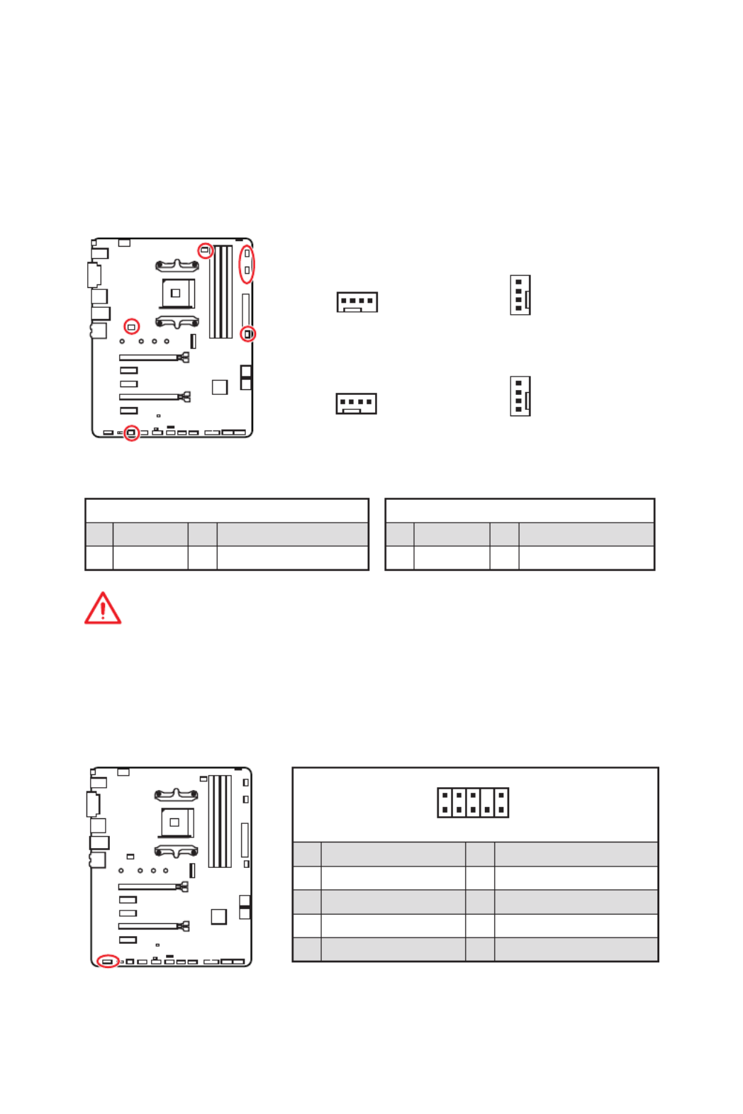
CPU_FAN1, PUMP_FAN1, SYS_FAN1~4: Fan Connectors
Fan connectors can be classified as PWM (Pulse Width Modulation) Mode or DC Mode.
PWM Mode fan connectors provide constant 12V output and adjust fan speed with
speed control signal. DC Mode fan connectors control fan speed by changing voltage.
When you plug a 3-pin (Non-PWM) fan to a fan connector in PWM mode, the fan speed
will always maintain at 100%, which might create a lot of noise. You can follow the
instruction below to adjust the fan connector to PWM or DC Mode. However, with auto-
detection mode fan connectors, the system will auto detect the fan mode.
Default DC Mode fan connectors
Default PWM Mode fan connectors
1
CPU_FAN1
1
SYS_FAN3/ SYS_FAN4
1
PUMP_FAN1
1
SYS_FAN1/ SYS_FAN2
PWM Mode pin definition
1 Ground 2 +12V
3 Sense 4 Speed Control Signal
DC Mode pin definition
1 Ground 2 Voltage Control
3 Sense 4 NC
Important
y
You can switch between PWM mode and DC mode and adjust fan speed in BIOS >
HARDWARE MONITOR.
y
Make sure fans are working properly after switching the PWM/ DC mode.
Pin definition of fan connectors
JAUD1: Front Audio Connector
This connector allows you to connect audio jacks on the front panel.
1
2 10
9
1 MIC L 2 Ground
3 MIC R 4 NC
5 Head Phone R 6 MIC Detection
7 SENSE_SEND 8 No Pin
9 Head Phone L 10 Head Phone Detection

37
Overview of Components
JBAT1: Clear CMOS (Reset BIOS) Jumper
There is CMOS memory onboard that is external powered from a battery located on
the motherboard to save system configuration data. If you want to clear the system
configuration, set the jumper to clear the CMOS memory.
Keep Data
(default)
Clear CMOS/
Reset BIOS
Resetting BIOS to default values
1. Power off the computer and unplug the power cord.
2. JBAT1Use a jumper cap to short for about 5-10 seconds.
3. Remove the jumper cap from JBAT1.
4. Plug the power cord and Power on the computer.
1
2 14
13
1 LPC Clock 2 3V Standby power
3 LPC Reset 4 3.3V Power
5 LPC address & data pin0 6 Serial IRQ
7 LPC address & data pin1 8 5V Power
9 LPC address & data pin2 10 No Pin
11 LPC address & data pin3 12 Ground
13 LPC Frame 14 Ground
JTPM1: TPM Module Connector
This connector is for TPM (Trusted Platform Module). Please refer to the TPM security
platform manual for more details and usages.
38 Overview of Components
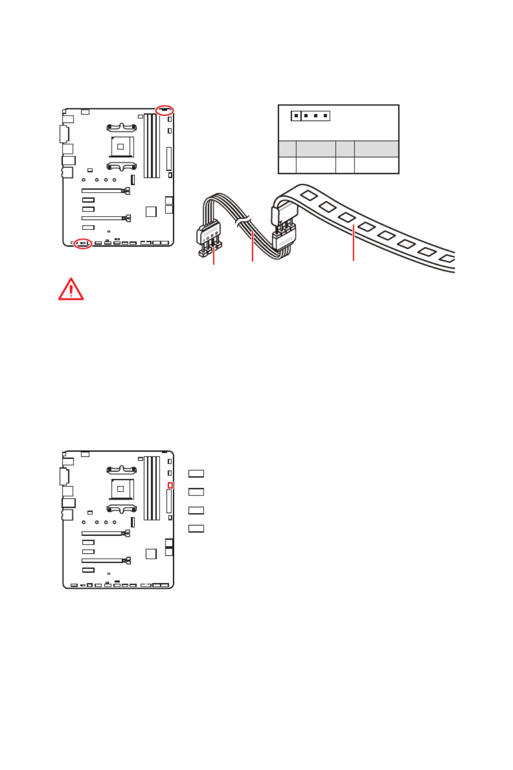
JRGB1~2: RGB LED connectors
The JRGB1/2 connectors allow you to connect the 5050 RGB LED strips 12V.
Important
y
The JRGB1/ JRGB2 connector supports up to 2 meters continuous 5050 RGB LED
strips (12V/G/R/B) with the maximum power rating of 3A (12V).
y
Always turn off the power supply and unplug the power cord from the power outlet
before installing or removing the RGB LED strip.
y
Please use MSI’s software to control the extended LED strip.
1
JRGB1/2
JRGB1
Extension cable 5050 RGB LED strips 12V
1
JRGB1/2
1 +12V 2 G
3 R 4 B
JRGB2
EZ Debug LEDs
These LEDs indicate the status of key components during booting process. When an
error is occurred, the corresponding LED stays lit until the problem is solved.
- indicates CPU is not detected or fail.CPU
- indicates DRAM is not detected or fail.DRAM
- indicates GPU is not detected or fail.VGA
- indicates the booting device is not detected BOOT
or fail.

39
BIOS Setup
BIOS Setup
The default settings offer the optimal performance for system stability in normal
conditions. You should always keep the default settings to avoid possible system
damage or failure booting unless you are familiar with BIOS.
Important
y
BIOS items are continuously update for better system performance. Therefore, the
description may be slightly different from the latest BIOS and should be for reference
only. You could also refer to the information panel for BIOS item description.HELP
y
The pictures in this chapter are for reference only and may vary from the product you
purchased.
y
The BIOS items will vary with the processor.
Entering BIOS Setup
Press Delete key, when the Press DEL key to enter Setup Menu, F11 to enter Boot
Menu message appears on the screen during the boot process.
Function key
F1: General Help list
F2: Add/ Remove a favorite item
F3: Enter Favorites menu
F4: Enter CPU Specifications menu
F5: Enter Memory-Z menu
F6: Load optimized defaults
F7: Switch between Advanced mode and EZ mode
F8: Load Overclocking Profile
F9: Save Overclocking Profile
F10: Save Change and Reset*
F12: Take a screenshot and save it to USB flash drive (FAT/ FAT32 format only).
Ctrl+F: Enter Search page
* When you press F10, a confirmation window appears and it provides the modification
information. Select between Yes or No to confirm your choice.

40 BIOS Setup
Resetting BIOS
You might need to restore the default BIOS setting to solve certain problems. There are
several ways to reset BIOS:
yGo to BIOS and press to load optimized defaults.F6
yShort the jumper on the motherboard.Clear CMOS
Important
Be sure the computer is off before clearing CMOS data. Please refer to the Clear
CMOS jumper section for resetting BIOS.
Updating BIOS
Updating BIOS with M-FLASH
Before updating:
Please download the latest BIOS file that matches your motherboard model from MSI
website. And then save the BIOS file into the USB flash drive.
Updating BIOS:
1. Press Del key to enter the BIOS Setup during POST.
2. Insert the USB flash drive that contains the update file into the computer.
3. M-FLASHSelect the tab and click on to reboot the system and enter the flash Yes
mode.
4. Select a BIOS file to perform the BIOS update process.
5. After the flashing process is 100% completed, the system will reboot
automatically.
Updating the BIOS with Live Update 6
Before updating:
Make sure the LAN driver is already installed and the internet connection is set
properly.
Updating BIOS:
1. Install and launch MSI LIVE UPDATE 6.
2. BIOS UpdateSelect .
3. ScanClick on button.
4. DownloadClick on icon to download and install the latest BIOS file.
5. Next In Windows mode Next StartClick and choose . And then click and to start
updating BIOS.
6. After the flashing process is 100% completed, the system will restart
automatically.

41
BIOS Setup
Updating BIOS with BIOS FLASHBACK+
Before updating:
Please download the latest BIOS file that matches your motherboard model from MSI ®
website and rename the BIOS file to . And then, save the file to the MSI.ROM MSI.ROM
root of USB flash drive.
Important
Only the FAT32 format USB flash drive supports updating BIOS by .BIOS FLASHBACK+
1. Connect power supply to and CPU_PWR1 ATX_PWR1. (No other components are
necessary but power supply.)
2. Plug the USB flash drive that contains the MSI.ROM file into the BIOS
FLASHBACK+ port on rear I/O panel.
3. Press the button to flash BIOS, and the LED next to BIOS FLASHBACK+
FLASHBACK+ button starts flashing.
4. After the flashing BIOS process is 100% completed, the LED would be off
simultaneously.

43
BIOS Setup
yInformation display CPU Memory Storage Fan Info Help- click on the , , , and buttons
on left side to display related information.
yFunction buttons LAN Option ROM, HD audio controller, - enable or disable the
AHCI/RAID, CPU Fan Fail Warning Control, Windows 10 WHQL support BIOS Log and
Review by clicking on their respective button.
yM-Flash M-Flash - click on this button to display the menu that provides the way to
update BIOS with a USB flash drive.
yHardware Monitor Hardware Monitor - click on this button to display the menu that
allows you to manually control the fan speed by percentage.
yFavorites menu - press the key to enter F3 Favorites menu. It allows you to create
personal BIOS menu where you can save and access favorite/ frequently-used BIOS
setting items.
Default HomePage - allows you to select a BIOS menu (e.g. SETTINGS, OC...,etc)
as the BIOS home page.
Favorite1~5 - allows you to add the frequently-used/ favorite BIOS setting items
in one page.
To add a BIOS item to a favorite page (Favorite 1~5)
1. Move the mouse over a BIOS item not only on BIOS menu but also on search
page.
2. Right-click or press F2 key.
3. Choose a favorite page and click on OK.
To delete a BIOS item from favorite page
1. Move the mouse over a BIOS item on favorite page (Favorite 1~5)
2. Right-click or press F2 key.
3. Delete OKChoose and click on .

44 BIOS Setup
Advanced Mode
Press or function key can switch between EZ Mode and Setup Mode switch F7
Advanced Mode in BIOS setup.
A-XMP switch
GAME BOOST
switch
System
information
Boot device
priority bar
BIOS menu
selection
Language
Search
Screenshot
Setup Mode switch
Menu display
BIOS menu
selection
y GAME BOOST switch/ Setup Mode switch/ Screenshot/ Language/ System
information/ Boot device priority bar - please refer to the descriptions of EZ Mode
Overview section.
y BIOS menu selection - the following options are available:
SETTINGS - allows you to specify the parameters for chipset and boot devices.
OC - allows you to adjust the frequency and voltage. Increasing the frequency may
get better performance.
M-FLASH - provides the way to update BIOS with a USB flash drive.
OC PROFILE - allows you to manage overclocking profiles.
HARDWARE MONITOR - allows you to set the speeds of fans and monitor voltages
of system.
BOARD EXPLORER - provides the information of installed devices on this
motherboard.
y Menu display - provides BIOS setting items and information to be configured.

45
BIOS Setup
SETTINGS
System Status
f System Date
Sets the system date. Use tab key to switch between date elements.
The format is <day> <month> <date> <year>.
<day> Day of the week, from Sun to Sat, determined by BIOS. Read-only.
<month> The month from Jan. through Dec.
<date> The date from 1 to 31 can be keyed by numeric function keys.
<year> The year can be adjusted by users.
f System Time
Sets the system time. Use tab key to switch between time elements.
The time format is <hour> <minute> <second>.
f SATA PortX
Shows the information of connected SATA device.
Important
If the connected SATA device is not displayed, turn off computer and re-check SATA
cable and power cable connections of the device and motherboard.
f System Information
Shows detailed system information, including CPU type, BIOS version, and Memory
(read only).
f DMI Information
Shows system information, desktop Board Information and chassis Information. (Read
only).
Advanced
f PCI Subsystem Settings
Sets PCI, PCI express interface protocol and latency timer. Press to enter the Enter
sub-menu.

46 BIOS Setup
fAbove 4G memory/ Crypto Currency mining [Disabled]
Enables or disables 64-bit capable devices to be decoded in above 4G address
space. It is only available if the system supports 64-bit PCI decoding.
[Enabled] Allows you to utilize more than 4x GPUs.
[Disabled] Disables this function.
fPCIe SlotX Lanes Configuration
PCIe lanes conguration is for MSI M.2 Xpander / MSI M.2 Xpander-Z / Other M.2
PCIe storage card. The options in this item will vary with the installed processor.
fACPI Settings
Sets ACPI parameters of onboard power LED behaviors. Press to enter the sub-Enter
menu.
fPower LED [Blinking]
Sets shining behaviors of the onboard Power LED.
[Dual Color] The power LED turns to another color to indicate the S3 state.
[Blinking] The power LED blinks to indicate the S3 state.
fCPU Over Temperature Alert [Auto]
Enables or disables the CPU overheating alert sound and message when CPU
temperature is over 55 and 75 degrees centigrade.
fIntegrated Peripherals
Sets integrated peripherals' parameters, such as LAN, HDD, USB and audio. Press
Enter to enter the sub-menu.
fOnboard LAN Controller [Enabled]
Enables or disables the onboard LAN controller.
fLAN Option ROM [Disabled]
Enables or disables the legacy network Boot Option ROM for detailed settings. This
item will appear when is enabled. Onboard LAN Controller
[Enabled] Enables the onboard LAN Boot ROM.
[Disabled] Disables the onboard LAN Boot ROM.
fNetwork Stack [Disabled]
Sets UEFI network stack for optimizing IPv4 / IPv6 function. This item is available
when Onboard LAN Controller is Enabled.
[Enabled] Enables UEFI network stack.
[Disabled] Disables UEFI network stack.
fIpv4 PXE Support [Enabled]
When , the system UEFI network stack will support Ipv4 protocol. This item Enabled
will appear when is Enabled. Network Stack
[Enabled] Enables the Ipv4 PXE boot support.
[Disabled] Disables the Ipv4 PXE boot support.

47
BIOS Setup
fIpv6 PXE Support [Enabled]
When , the system UEFI network stack will support Ipv6 protocol. This item Enabled
will appear when is enabled.Network Stack
[Enabled] Enables the Ipv6 PXE boot support.
[Disabled] Disables the Ipv6 PXE boot support.
fSATA Mode [AHCI Mode]
Sets the operation mode of the onboard SATA controller.
[AHCI Mode] Specify the AHCI mode for SATA storage devices. AHCI (Advanced
Host Controller Interface) offers some advanced features to enhance
the speed and performance of SATA storage device, such as Native
Command Queuing (NCQ) and hot-plugging.
[RAID Mode] Enables RAID function for SATA storage devices.
fSATAx Hot Plug [Disabled]
Allows user to enable or disable the SATA hot plug support.
[Enabled] Enables hot plug support for the SATA ports.
[Disabled] Disables hot plug support for the SATA ports.
fHD Audio Controller [Enabled]
Enables or disables the onboard High Definition Audio controller.
f Integrated Graphics Conguration (optional)
Adjusts integrated graphics settings for optimum system. Press Enter to enter the
sub-menu.
fInitiate Graphic Adapter [PEG] (optional)
Selects a graphics device as the primary boot device.
[IGD] Integrated Graphics Display.
[PEG] PCI-Express Graphics Device.
fIntegrated Graphics [Auto] (optional)
If set to Force, BIOS will enable the integrated graphics controller.
fUMA Frame Buffer Size [Auto] (optional)
Selects a fixed amount of system memory allocated to the onboard graphics. This
item will be available when is enabled. Integrated Graphics
f USB Conguration
Sets the onboard USB controller and device function. Press to enter the sub-Enter
menu.
fXHCI Hand-off [Enabled]
Enables or disables XHCI hand-off support for the operating system without XHCI
hand-off feature.

48 BIOS Setup
fLegacy USB Support [Enabled]
Sets Legacy USB function support.
[Auto] The system will automatically detect if any USB device is connected
and enable the legacy USB support.
[Enabled] Enable the USB support under legacy mode.
[Disabled] The USB devices will be unavailable under legacy mode.
f Super IO Conguration
Sets system Super I/O chip parameters including LPT and COM ports. Press Enter to
enter the sub-menu.
fSerial (COM) Port 0 Configuration
Sets detailed configuration of serial(COM) port 0. Press Enter to enter the sub-
menu.
fSerial Port [Enabled]
Enables or disables serial port.
fSerial (COM) Port0 Settings [Auto]
Sets serial port 0. If set to Auto, BIOS will optimize the IRQ automatically or you
can set it manually.
f Power Management Setup
Sets system Power Management of ErP and AC Power Loss behaviors. Press Enter to
enter the sub-menu.
fErP Ready [Disabled]
Enables or disables the system power consumption according to ErP regulation.
[Enabled] Optimize the system power consumption according to ErP
regulation. It will not support S4 & S5 wake up by USB, PCI and PCIe
devices.
[Disabled] Disables this function.
fRestore after AC Power Loss [Power Off]
Sets the system behaviors while encountering the AC power loss.
[Power Off] Leaves the system in power off state after restoring AC power.
[Power On] Boot up the system after restoring AC power.
[Last State] Restores the system to the previous state (power on/ power off)
before AC power loss.
fSystem Power Fault Protection [Disabled]
Enables or disables the system to boot up when detecting abnormal voltage input.
[Enabled] Protect the system from unexpected power operating and remain
the shut down status.
[Disabled] Disables this function.
f Windows OS Configuration
Sets Windows detailed configuration and behaviors. Press to enter the sub-Enter
menu.

49
BIOS Setup
fWindows 10 WHQL Support [Disabled]
Enables the supports for Windows 10 or disables for other operating systems.
Before enabling this item, make sure all installed devices & utilities (hardware &
software) should meet the Windows 10 requirements.
[Enabled] The system will switch to UEFI mode to meet the Windows
requirement.
[Disabled] Disables this function.
fInternal GOP Configuration
Manages the onboard Graphics Output Protocol (GOP). Press to enter Enter
the sub-menu. This sub-menu will appear when is Windows 10 WHQL Support
enabled.
fSecure Boot
Sets the Windows secure boot to prevent the unauthorized accessing. Press Enter
to enter the sub-menu. This sub-menu will appear when Windows 10 WHQL
Support is enabled.
fWake Up Event Setup
Sets system wake up behaviors for different sleep modes. Press to enter the Enter
sub-menu.
fWake Up Event By [BIOS]
Selects the wake up event by BIOS or operating system.
[BIOS] Activates the following items, set wake up events of these items.
[OS] The wake up events will be defined by OS.
fResume By RTC Alarm [Disabled]
Disables or enables the system wake up by RTC Alarm.
[Enabled] Enables the system to boot up on a scheduled time/ date.
[Disabled] Disables this function.
fDate (of month) Alarm/ Time (hh:mm:ss) Alarm
Sets RTC alarm date/ Time. If Resume By RTC Alarm is set to [Enabled], the system
will automatically resume (boot up) on a specied date/hour/minute/second in
these elds (using the and keys to select the date & time settings).+ -
fResume By PCI-E Device [Disabled]
Enables or disables the wake up function of installed PCI-E expansion cards,
integrated LAN controllers or USB devices which are supported by third party
integrated chips.
[Enabled] Enables the system to be awakened from the power saving modes
when activity or input signal of PCIe device is detected.
[Disabled] Disables this function.
fResume by USB Device [Disabled]
Disables or enables system wake up from S3/S4 by USB device.
[Enabled] Enables the system to be awakened from sleep state when activity of
USB device is detected.
[Disabled] Disables this function.

50 BIOS Setup
fResume From S3/S4/S5 by PS/2 Mouse [Disabled]
Enables or disables the system wake up by PS/2 mouse.
[Enabled] Enables the system to be awakened from S3/ S4/ S5 state when
activity of PS/2 mouse is detected.
[Disabled] Disables this function.
fResume From S3/S4/S5 by PS/2 Keyboard [Disabled]
Enables or disables the system wake up by PS/2 keyboard.
[Any Key] Enables the system to be awakened from S3/ S4/ S5 state when
activity of any key on PS/2 keyboard is detected.
[Hot Key] Enables the system to be awakened from S3/ S4/ S5 state when
activity of hot key on PS/2 keyboard is detected.
[Disabled] Disables this function.
fHot Key [Ctrl+Space]
Selects a combination of keys as a hot key to wake the system. This item appears
when you set the Resume From S3/S4/S5 by PS/2 Keyboard Hot Key to .
fSecure Erase+
Enables or disables Secure Erase+ function. is the best way to Secure Erase+
effectively wipe all data from a SSD. Please note that data of SSD will be erased after
enabling Secure Erase+.
fRealtek PCIe GBE Family Controller
Shows driver information and configuration of the ethernet controller parameter.
Boot
Sets the sequence of system boot devices.
fFull Screen Logo Display [Enabled]
Enables or disables to show the full screen logo while system POST.
[Enabled] Shows the logo in full screen.
[Disabled] Shows the POST messages.
fBootup NumLock State [On]
Select the keyboard NumLock state upon bootup.
fInfo Block effect [Unlock]
Sets the state of information block.Help
[Unlock] Sliding effect.
[Lock] Fix the information block on the screen.Help
fPOST Beep [Disabled]
Enables or disables POST beep.
fAUTO CLR_CMOS [Disabled]
Enables or disables the CMOS data to be resumed automatically when the system
cannot boot to OS and reboot repeatedly.

51
BIOS Setup
f Boot Mode Select [LEGACY+UEFI]
Sets the system boot mode from legacy or UEFI architecture depending on OS
installation requirement. This item will become un-selectable and will be configured
automatically by BIOS when is enabled. Windows 10 WHQL Support
[UEFI] Enables UEFI BIOS boot mode support only.
[LEGACY+UEFI] Enables both Legacy BIOS boot mode and UEFI BIOS boot
mode.
f FIXED BOOT ORDER Priorities/ UEFI USB Key Drive BBS Priorities/ USB Key Drive
BBS Priorities
Sets device priority for system boot.
f Boot Option Priorities
These items are used to prioritize the installed boot devices.
Security
f Administrator Password
Sets administrator password for system security. User has full rights to change the
BIOS items with administrator password. After setting the administrator password, the
state of this item will show Installed.
f User Password
Sets User Password for system security. User has limited rights to change the BIOS
items with user password. This item will be available when administrator password is
set. After setting the user password, the state of this item will show Installed.
f Password Check [Setup]
Selects a condition that will request the password.
[Setup] A password will be requested for entering the BIOS Setup.
[Boot] A password will be requested for booting the system .
f Password Clear [Enabled]
Enables or disables the clear CMOS behavior to clear a set password.
[Enabled] The password will be erased after clear CMOS.
[Disabled] The password will always be kept .
Important
When selecting the Administrator / User Password items, a password box will appear
on the screen. Type the password then press . The password typed now will Enter
replace any previous set password from CMOS memory. You will be prompted to
confirm the password. You may also press key to abort the selection.Esc
To clear a set password, press when you are prompted to enter a new password. Enter
A message will confirm the password is being disabled. Once the password is disabled,
you can enter the setup and OS without authorization.

52 BIOS Setup
fTrusted Computing
Sets TPM (Trusted Platform Module) function.
fSecurity Device Support [Disabled]
Enables or disables the TPM function to build the endorsement key for accessing
the system.
fAMD fTPM switch [AMD CPU fTPM]
Selects TPM device. This item will appear when Security Device Support is
enabled.
[AMD CPU fTPM] Select it for AMD Firmware TPM.
[AMD CPU fTPM Disabled] Select it for Discrete TPM.
fDevice Select [Auto]
Sets the version of the TPM device. The version must be identical with the device.
Sets to , system will detect the TPM 2.0 or TPM 1.2 model automatically. Auto
fChassis Intrusion Configuration
Press to enter the sub-menu. Enter
fChassis Intrusion [Disabled]
Enables or disables recording messages while the chassis is opened. This function
is ready for the chassis equips a chassis intrusion switch.
[Enabled] Once the chassis is opened, the system will record and issue a
warning message.
[Reset] Clear the warning message. After clearing the message, please
return to or .Enabled Disabled
[Disabled] Disables this funcion.
Save & Exit
fDiscard Changes and Exit
Exit BIOS setup without saving any change.
fSave Changes and Reboot
Save all changes and reboot the system.
fSave Changes
Save current changes.
fDiscard Changes
Discard all changes and restore to the previous values.
fRestore Defaults
Restore or load all default values.
fBoot Override
The installed boot-able devices will appear on this menu, you can select one of them to
be the boot device.

53
BIOS Setup
OC
Important
y
Overclocking your PC manually is only recommended for advanced users.
y
Overclocking is not guaranteed, and if done improperly, it could void your warranty or
severely damage your hardware.
y
If you are unfamiliar with overclocking, we advise you to use GAME BOOST function
for easy overclocking.
y
The BIOS items in OC menu will vary with the processor.
f OC Explore Mode [Normal]
Enables or disables to show the normal or expert version of OC settings.
[Normal] Provides the regular OC settings in BIOS setup.
[Expert] Provides the advanced OC settings for OC expert to configure in BIOS
setup.
Note: We use * as the symbol for the OC settings of Expert mode.
f CPU Ratio [Auto]
Sets the CPU ratio that is used to determine CPU clock speed. This item can only be
changed if the processor supports this function.
f Core Performance Boost [Auto]
Enables or disables the Core Performance Boost (CPB). This item appears when the
installed CPU supports this function.
f Downcore Control [Auto] (optional)
Sets the number of processor cores to be used. This item appears when the installed
CPU supports this function.
f A-XMP [Disabled]
Please enable A-XMP or select a profile of memory module for overclocking the
memory. This item will be available when the installed processor, memory modules
and motherboard support this function.
f DRAM Frequency [Auto]
Sets the DRAM frequency. Please note the overclocking behavior is not guaranteed.

54 BIOS Setup
fAdjusted DRAM Frequency
Shows the adjusted DRAM frequency. Read-only.
fMemory Try It ! [Disabled]
It can improve memory compatibility or performance by choosing optimized memory
preset.
fAdvanced DRAM Conguration
Press to enter the sub-menu. User can set the memory timing for each/ all Enter
memory channel. The system may become unstable or unbootable after changing
memory timing. If it occurs, please clear the CMOS data and restore the default
settings. (Refer to the Clear CMOS jumper section to clear the CMOS data, and enter
the BIOS to load the default settings.)
fDigitALL Power
Press to enter the sub-menu. Controls the digital powers related to CPU PWM.Enter
fCPU Loadline Calibration Control [Auto]
The CPU voltage will decrease proportionally according to CPU loading. Higher
load-line calibration could get higher voltage and good overclocking performance,
but increase the temperature of the CPU and VRM. If set to , BIOS will Auto
congure this setting automatically.
fCPU NB Loadline Calibration Control [Auto]
The CPU-NB voltage will decrease proportionally according to CPU-NB loading.
Higher load-line calibration could get higher voltage and good overclocking
performance, but increase the temperature. If set to , BIOS will congure this Auto
setting automatically.
fCPU Over Voltage Protection [Auto]
Sets the voltage limit for CPU over-voltage protection. If set to , BIOS will Auto
congure this setting automatically. Higher voltage provides less protection and
may damage the system.
fCPU Under Voltage Protection [Auto]
Sets the voltage limit for CPU under-voltage protection. If set to , BIOS will Auto
congure this setting automatically. Higher voltage provides less protection and
may damage the system.
fCPU Over Current Protection [Auto]
Sets the current limit for CPU over-current protection. If set to , BIOS will Auto
congure this setting automatically.
[Auto] This setting will be configured automatically by BIOS.
[Enhanced] Extends the current range for over-current protection.
fVR 12VIN OCP Expander [Auto]
Expands the limitation of VR Over Current Protection with 12V input voltage. The
higher expanding value indicates less protection. Therefore, please adjust the
current carefully if needed, or it may damage the CPU/ VR MOS. If set to "Auto",
BIOS will configure this setting automatically.

55
BIOS Setup
f CPU Voltages control [Auto]
These options allows you to set the voltages related to CPU. If set to , BIOS will Auto
set these voltages automatically or you can set it manually.
f DRAM Voltages control [Auto]
These options allows you to set the voltages related to memory. If set to , BIOS Auto
will set these voltages automatically or you can set it manually.
f Memory Changed Detect [Enabled]*
Enables or disables the system to issue a warning message during boot when the
memory has been replaced.
[Enabled] The system will issue a warning message during boot and then you have
to load the default settings for new devices.
[Disabled] Disables this function and keeps the current BIOS settings.
f CPU Specications
Press to enter the sub-menu. This sub-menu displays the information of Enter
installed CPU. You can also access this information menu at any time by pressing [F4].
Read only.
fCPU Technology Support
Press to enter the sub-menu. The sub-menu shows the key features of Enter
installed CPU. Read only.
f MEMORY-Z
Press to enter the sub-menu. This sub-menu displays all the settings and Enter
timings of installed memory. You can also access this information menu at any time by
pressing [F5].
fDIMMx Memory SPD
Press to enter the sub-menu. The sub-menu displays the information of Enter
installed memory. Read only.
f CPU Features
Press to enter the sub-menu.Enter
fGlobal C-state Control [Enabled] (optional)
Enables/ disables IO based C-state generation and DF C-states.
fSimultaneous Multi-Threading [Enabled] (optional)
Enables/ disables the AMD Simultaneous Multi-Threading. This item appears when
the installed CPU supports this technology.
fOpcache Control [Auto] (optional)
Enables/ disables Opcache. Opcache stores recent decode instruction to save
the decoding time when the instruction is repeated. And it may increase the CPU
performance and reduce the power consumption slightly.
fIOMMU Mode (optional)
Enables/disables the IOMMU (I/O Memory Management Unit) for I/O Virtualization.

57
BIOS Setup
M-FLASH
M-FLASH provides the way to update BIOS with a USB flash drive. Please download
the latest BIOS file that matches your motherboard model from MSI website, save the
BIOS file into your USB flash drive. And then follow the steps below to update BIOS.
1. Insert the USB flash drive that contains the update file into the computer.
2. M-FLASHClick on tab, a demand message will be prompted. Click on Yes to
reboot and enter the flash mode.
3. The system will enter the flash mode and a file selection menu will appear after
rebooting.
4. Select a BIOS file to perform the BIOS update process.
5. After the flashing process is 100% completed, the system will reboot
automatically.

58 BIOS Setup
OC PROFILE
f Overclocking Prole 1/ 2/ 3/ 4/ 5/ 6
Overclocking Profile 1/ 2/ 3/ 4/ 5/ 6 management. Press to enter the sub-menu.Enter
fSet Name for Overclocking Profile 1/ 2/ 3/ 4/ 5/ 6
Name the current overclocking prole.
fSave Overclocking Profile 1/ 2/ 3/ 4/ 5/ 6
Save the current overclocking prole.
fLoad Overclocking Profile 1/ 2/ 3/ 4/ 5/ 6
Load the current overclocking prole.
fClear Overclocking Profile 1/ 2/ 3/ 4/ 5/ 6
Clear the current overclocking profile.
f OC Prole Load from ROM
Load OC profile from BIOS ROM.
f OC Prole Save to USB
Save OC profile to the USB flash drive. The USB flash drive should be FAT/ FAT32
format only.
f OC Prole Load from USB
Load OC profile from the USB flash drive. The USB flash drive should be FAT/ FAT32
format only.

59
BIOS Setup
HARDWARE MONITOR
Temperature
& Speed
Fan Manage
Temperature/
Voltage display
Setting
Buttons
f Temperature & Speed
Shows the current CPU temperature, system temperature and fans' speeds.
f Fan Manage
PWM - allows you to select the PWM mode for fan operation.
DC - allows you to select the DC mode for fan operation.
Fan step up/ down time - allows you to set the period of fan step up/ down.
Smart Fan Mode field - allows you to drag the gradient points to configure
the fan target values for mode. Smart Fan Smart Fan can control the fan speed
automatically depending on the CPU temperature to keep it with in a specific range.
If the current CPU temperature reaches to the target value, the Smart Fan function
will be activated.
Important
y
The changing will achieve after you save the changes and reboot the system.
y
Make sure fans are working properly after switching the PWM/ DC mode.
f Settings Buttons
All Full Speed - configures all fans to run at full operating speed.
All Set Default - configures all fans to run at default operating speed.
All Set Cancel - discards current changes and restores previous operating fan
speeds .
f Temperature/ Voltage display
Shows CPU/ system temperature and the current voltages of CPU, system and
memory.

60 Software Description
Software Description
Please download and update the latest utilities and drivers at www.msi.com
Installing Windows ® 10
1. Power on the computer.
2. Insert the Windows ® 10 disc into your optical drive.
3. Press the button on the computer case.Restart
4. Press key during the computer POST (Power-On Self Test) to get into Boot F11
Menu.
5. Select your optical drive from the Boot Menu.
6. Press any key when screen shows Press any key to boot from CD or DVD...
message.
7. Follow the instructions on the screen to install Windows ® 10.
Installing Drivers
1. Start up your computer in Windows ® 10.
2. Insert MSI ® Driver Disc into your optical drive.
3. The installer will automatically appear and it will find and list all necessary
drivers.
4. InstallClick button.
5. The software installation will then be in progress, after it has finished it will
prompt you to restart.
6. OKClick button to finish.
7. Restart your computer.
Installing Utilities
Before you install utilities, you must complete drivers installation.
1. Insert MSI ® Driver Disc into your optical drive.
2. The installer will automatically appear.
3. UtilitiesClick tab.
4. Select the utilities you want to install.
5. InstallClick button.
6. The utilities installation will then be in progress, after it has finished it will prompt
you to restart.
7. OKClick button to finish.
8. Restart your computer.

61
Software Description
APP MANAGER
APP MANAGER is a handy management application for integration of MSI applications
and software interface. Providing easy shortcut entrance and real-time update
information of all the MSI software and applications.
APP list
Total Install/ Update
Motherboard
Information
y APP list - shows all the applications and software be supported by this motherboard.
An icon represents a entrance to the application.
Colorful icon - a colorful icon means that the application had have been
installed successfully and it is available. Double click on desired icon to access
the application. A refresh icon shows to inform you that the application has a
update version.
Gray icon - the icon with gray painting means that the application is not available
and you have to install it if necessary. Double click on the gray icon and the update
information will show. Click on the INSTALL button to install the application.
y Motherboard Information - shows the model name of motherboard.
y Total Install/ Update - click on this tab to update/ install all the applications.
Important
Please note that, once you uninstall the APP MANAGER, all the MSI applications and
software will be uninstalled simultaneously.

62 Software Description
LIVE UPDATE 6
LIVE UPDATE 6 is an application for the MSI ® system to scan and download the latest
drivers, BIOS and utilities. With LIVE UPDATE 6, you don’t need to search the drivers
on websites, and don’t need to know the models of motherboard and graphics cards.
LIVE UPDATE 6 will download the appropriate drivers automatically.
Download Options
Download List
Scan / Download / Total
Installer button
System Information
Last Scanned Date
There are Live Update, History, Setting System Informationand tabs at the top. You
can click the tab to switch the control panel.
y Live Update - When you launch LIVE UPDATE 6, you will see the Live update tab at
first. This tab allows you to select files to download. You can also read the relevant
information by clicking the information icon on the right of the item listed.
y History - shows the downloading history.
y Setting - allows you to specify the frequency that LIVE UPDATE 6 remind you to
update.
y System Information - displays the information of the system.
y FAQ - shows Frequently Asked Questions.
y Online Help - shows Online Help information.
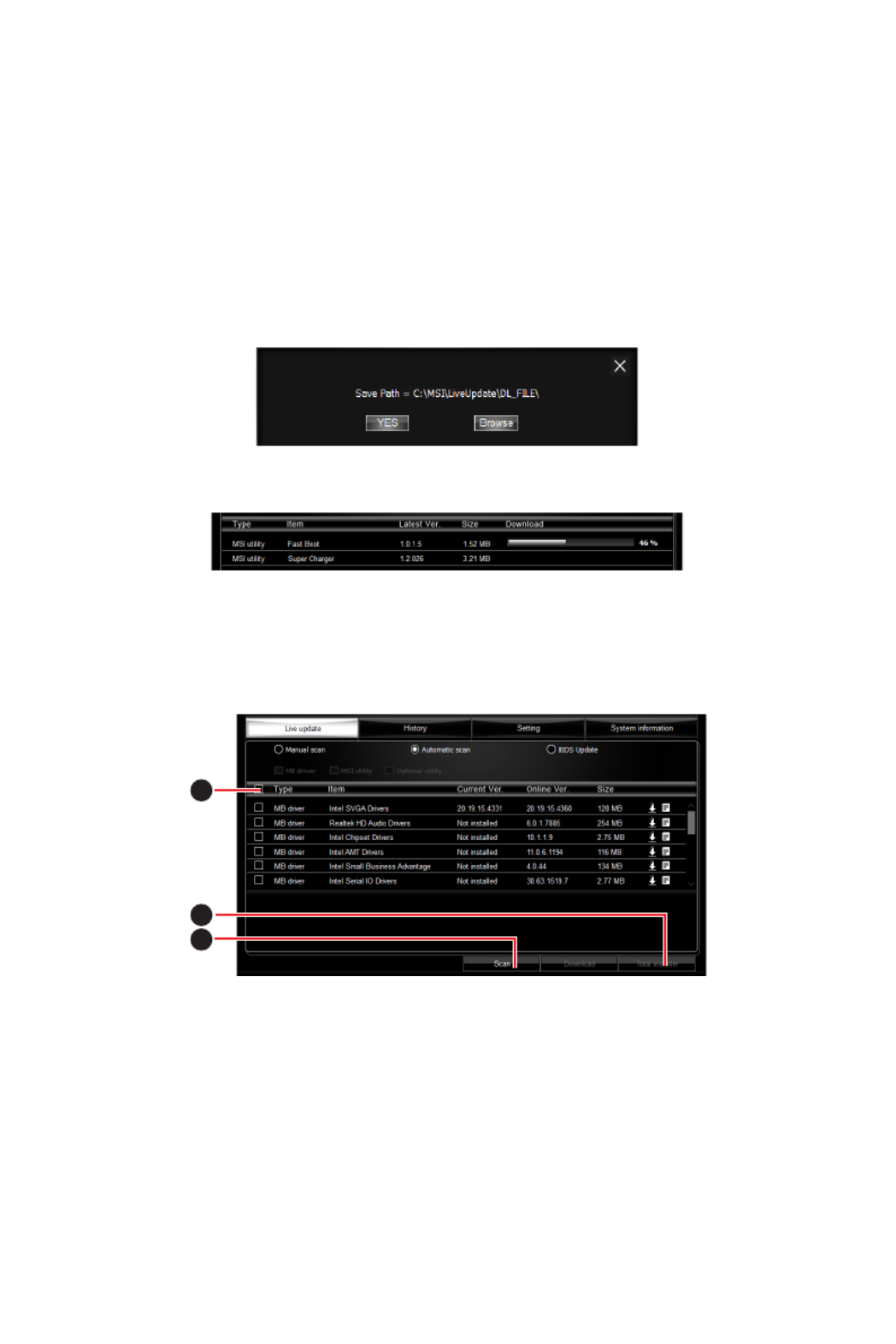
Updating The System
This section describes how to update your system with LIVE UPDATE 6. Please follow
the steps below:
1
2
4
5
3
63
Software Description
1. Live UpdateSelect the tab.
2. Automatic scanChoose , system will automatically scan all the items and search
for the latest update files. Or you can choose and select the items you Manual scan
wish to scan.
3. ScanClick the button at the bottom. It may take several moments to complete the
process.
4. When the download list appears, please select the items you intend to update.
5. DownloadClick button at the bottom.
6. Save PathWhen prompt, you can specify a download directory.
7. When downloading you will see the screen below. It may take several moments to
complete the process.
8. To install the applications, simply unpack the packages and install.
Total Installer
Total Installer is a convenient feature to simplify frequent installing procedure. To use
Total Installer:
1
2
3
1. Scan Live Update updates in tab.
2. Select AllCheck the check-box you intend to update.
3. Total InstallerClick the button. LIVE UPDATE 6 will automatically install them.
4. When prompted, click to complete the Total Installer procedureOK
5. Reboot your system.
64 Software Description
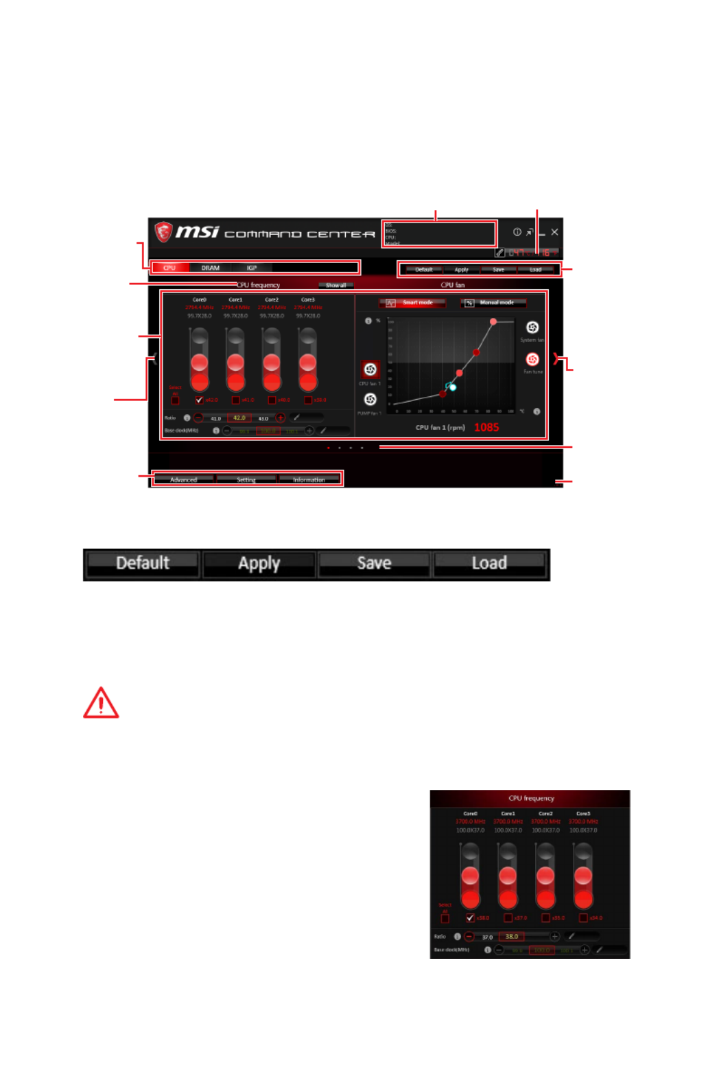
COMMAND CENTER
COMMAND CENTER is an user-friendly software and exclusively developed by MSI,
helping users to adjust system settings and monitor status under OS. With the help
of COMMAND CENTER, making it possible to achieve easier and efficient monitoring
process and adjustments than that under BIOS. In addition, the COMMAND CENTER
can be a server for mobile remote control application.
Feature Menu
CPU TemperatureSystem Information
Feature Title
Feature
Control Panel
Previous
Feature
Next Feature
Profile
Buttons
Option Buttons
Page Indicator
Resize Corner
Profile Buttons
y Default - load the default values for the current feature.
y Apply - apply your changes.
y Save - store values in the file with individual file extension.
y Load - load the values from the file.
Important
Every time you shut down the system, the configured setting will be restored to the
factory default. If you want to use the saved settings, you have to load it every time by
clicking the and Load Apply buttons.
CPU Frequency
CPU Frequency control panel allows you to change
CPU Ratio and Base clock. You can see the current
frequency of each CPU core on the top of the panel.

65
Software Description
CPU Fan
CPU Fan control panel provides and Smart mode
Manual Mode. You can switch the control mode by
clicking the and buttons Smart Mode Manual Mode
on the top of the CPU Fan control panel.
y Manual Mode - allows you to manually control the
CPU fan speed by percentage.
y Smart Mode - a linear fan speed control feature.
The control panel contains 4 dots allows you to
drag and adjust the Smart Speed slopes. The fan
speed will be changed along these lines with CPU
temperature. The white dot will create strip chart in
real time.
y System Fan Button - to open the system fan control
panel in new window.
y Fan Tune Button - to automatically optimize the
smart fan setting.
Manual Mode
Smart Mode
IGP Frequency & GT Voltage
y IGP Frequency - Allows you to adjust the IGP ratio,
and shows the IGP clock, ratio and frequency.
y GT Voltage - Allows you to adjust the GT voltage.
The risky values are displayed in red.
DRAM Frequency & DRAM Voltage
y DRAM Frequency - Shows the DRAM clock, ratio
and frequency.
y DRAM Voltage - Allows you to adjust the DRAM
voltage. The risky values are displayed in red.
CPU Voltage
CPU Voltage control panel allows you to control the
CPU voltage.

66 Software Description
Option Buttons - Advanced
When click the button, The Advanced Voltage DRAM, Fan and icons will appear.
y Voltage - allows you to adjust advanced voltage values of CPU and chipset.
y Fan - allows you to control the system fans speed.
y DRAM - shows the current Advanced DRAM parameters, and allows you to change
the settings by selecting values from the drop-down menu on the right hand side.
Option Buttons - Setting
When click the button, The Setting Record Warning Mobile Control , and icons will
appear.
y Record - allows you to monitor the status of voltage, fan speed and temperature in
real time.
To filter record charts, select the check box next to the items.
When click the button, the chart pane will start to show the recording chart. Play
If you want to check the value of a specific spot on chart, please move the orange
vertical line to the spot.
History Record stores the data and names with date and time.
To make a history record: Select items and click the Record button. When
finished, click the Record button again. The data will be stored in the drop-down
menu.
To load a record, click the drop-down menu and select one from the list.
To delete a record, select the record that you want to delete, and click the Trash
Can icon.

67
Software Description
y Warning - contains fields of voltage, fan speed and temperature for you to set the
threshold values. When system detects the status over your settings, a warning
message will pop-up.
y Mobile Control - is only available for the motherboard with the built-in WiFi module.
It allows you to enable/disable the COMMAND CENTER Remote Server. Please refer to
the instruction on the Mobile Control control panel.
y To start remote control: (optional)
1. Download and install MSI ® COMMAND CENTER APP to your mobile device.
2. COMMAND CENTER Remote Server Mobile ControlEnable on the panel.
3. SoftAP ManagementEnable .
4. SSID Password ApplyEnter and , and then click the button.
5. Activate Wi-Fi ® on your mobile device and connect to SoftAP with the SSID.
6. MSIRun ® COMMAND CENTER APP on your mobile device.
7. Find the IP address on the area, and enter the IP SoftAP Management Setting
address on your MSI ® COMMAND CENTER APP to link your system.
8. Press Refresh MSI on the ® COMMAND CENTER APP to verify that monitoring and
OC functions are working properly.
Option Buttons - Information
When click the button, The Information Motherboard CPU Memory HW monitor, , and
icons will appear.
You can click the icons to open the related information.
Gadget Mode
COMMAND CENTER provides a gadget mode to
monitor the system status. You can switch between
gadget mode and full mode by clicking the arrow
icon on the top left.
y To arrange gadgets:
1. Click the Spanner icon on the Gadget mode,
a configuration panel will slide out.
2. Select the check box next to the items.
3. CloseClick the button.

68 Software Description
GAMING APP
GAMING APP is an application designed to quickly control your system for improving
gaming performance.
Information Button
Setting Button
Control Mode Buttons
Gaming Function
Buttons
CPU Frequency GPU Frequency
Cooler Boost
Peripheral Device
Function Buttons
Remote Control Setting Button
ySetting Button - allows you to choose running GAMING APP when Windows starts or
let GAMING APP to overwrite the VGA fan control function.
yInformation Button - shows the information of this application.
yCPU Frequency - shows the current CPU frequency.
yGPU Frequency - shows the current GPU frequency.
yControl Mode Buttons
OC Mode - apply turbo frequency to CPU and OC frequency to GPU.
Gaming Mode - automatically optimize the CPU ratio and the GPU clock.
Silent Mode - reverts the CPU ratio and GPU clock to the default values.
yGaming Function Buttons OSD Eye Rest - allows you to use and functions.
yPeripheral Device Function Buttons Gaming Hotkey, Mouse - allows you to set the
Master VR Ready Voice Boost, and functions.
yRemote Control Setting Button - available for the motherboards with built-in or
discrete WiFi module. It allows you to set up and Name Password to link the android
device and the motherboard. Please follow the steps below to complete the remote
control setting.
1. Download and install the MSI® GAMING APP APP to your android device.
2. Name Password Remote Control SettingSet up a set of and on the panel, and
then click the Apply button.
3. Connect your android device and motherboard to the same local area network.
4. MSIRun ® GAMING APP APP on your android device.
5. Press the Remote Control Setting MSI icon on the ® GAMING APP APP to find the
paired device you set in the Name Remote Control Setting panel.
6. Password Remote Control SettingEnter the you set in the panel.
7. Finally, you can use the MSI® GAMING APP APP to control your motherboard with
the android device.

70 Software Description
Gaming Hotkey
Gaming Hotkey provides instant control of the system through user defined hotkeys.
Categories Toggle
Hotkey Manager
Current Hotkeys
Gaming Hotkey ON/OFF
y Gaming Hotkey ON/OFF - allows you to turn ON/OFF the Gaming Hotkey function.
y Categories Toggle - allows you to toggle over the Hotkey categories.
Macro Genie - provides the keyboard and mouse macro record function and
allows you to define the hotkeys for the macro recorder.
1. RecordClick on the button to start the keyboard and mouse macro recorder.
2. StopClick on the button to stop the recorder.
3. Key-in a file name and set-up the parameter for the macro.
4. Finally, click on the button to save the recorded macro. Save
Windows Keys - allows you to define hotkeys to replace Windows default
keyboard shortcuts.
Login Keys - provides hotkey login function.
MSI Smart Keys - allows you to define hotkeys for MSI Smart Keys.
y Hotkey Manager - allows you to create, edit and delete hotkeys.
y Current Hotkeys - shows all existing hotkeys.
Important
y
The , , Caps Lock Num Lock Scroll Lock Window Home Application BackSpace, , and
keys can not be used as Hotkeys.
y
Some key combinations are reserved for use by Microsoft Windows and can not be
assigned as a hotkey.

71
Software Description
Mouse Master
Mouse Master provides mouse macro function. You can also use it to change DPI of
your mouse.
Delay Time
Macro Hot Key DPI Hot Key
Test Area
Clear Button
Mouse Action
DPI Setting
Default Button
Action List
Edit Buttons
Load Button
Save Button
y Delay Time - allows you to apply a delay time in mouse macro.
y Macro Hot Key - allows you to assign a hotkey from A to Z to activate the macro.
y Mouse Action - assigns mouse actions to the macro.
New - captures the mouse coordinate and add to the macro.
Left - add a left-click to the macro.
Middle - add a middle-click to the macro.
Left - add a left-click to the macro.
y Action List - shows the actions of the current macro.
y Edit Buttons - there 3 buttons for editing the macro.
Run - activates the macro.
Delete - removes the selected action from the macro.
Clear - removes all actions from the macro.
y Load Button - allows you to load a macro.
y Save Button - allows you to save the macro to a file.
y DPI Setting - allows you select the mouse DPI from the drop-down menu.
y Default Button - reverts to the default DPI setting.
y DPI Hot Key - allows you to assign a hotkey from A to Z to activate the DPI setting.
Please note that you muse hold the hotkey to keep the DPI setting. When you release
the hotkey, the DPI setting will be reverted to default.
y Test Area - allows you to test the mouse movement.
y Clear Button - clears the test area.

73
Software Description
y Performance information - displays the system performance diagram of enabled
mode.
y Setting - enables or disables .Run X-BOOST when windows starts
X-BOOST
The MSI allows you to select the system performance mode to meet your X-BOOST
current system environment or support faster storage access speed for your external
storage or memory cards.
Easy
In page, you can select one system performance mode to meet the current Easy
system environment.
Setting
Performance
information
Performance
mode
y Performance mode - moves over the mouse to any one of performance mode and
click on the button to enable it.ON
Important
The mode is the default of system performance.Customize
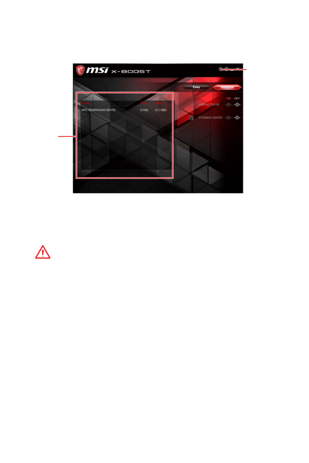
74 Software Description
Advance
In page, you can enable the the and Advance USB SPEED UP, STORAGE BOOST VR
BOOST.
Setting
Device
information
y Device information - displays the information and current transfer rates/ access
speeds of USB/ storage devices.
y Setting - enables or disables Run X-BOOST when windows starts.
y USB SPEED UP - supports faster data transfer rates of the USB storage devices.
y STORAGE BOOST - supports faster access speed of storage device.
Important
y
Please note that you can only select one mode at a time from Easy or Advance page
as MSI function.X-BOOST
y
The improved transfer rate/ access speed will vary with the USB/ storage device.

75
Software Description
ySYNC PROFILE - In this section, you may apply different LED setting to your device.
All Sync - Default: All the Sync device bubble would appear red.
MYSTIC LIGHT
MYSTIC LIGHT is an application allows you to control LED lights of MSI products.
For some earlier products, you can go to product download page to download the
applicable LED control software.
Main Screen
The Main screen is used to configure what devices need to be synchronized and LED
light effect options.
Right hand
side panel
ON/ OFF All LED
SYNC PROFILE
Live Preview
Apply Button
Save Button
Please noted that for light effect, the option would be
more or less depending on the devices you have, it will
only list the light effects which are available for all
included devices.
yON/OFF All LED - By toggling Off/On here, you
disable/enable all the LED on supported gaming gear,
memory, graphics card and motherboard etc.
For the color section, you can always select a different
color but it won’t apply to the device that does not have
such color.
To change the LED color & effect, use the panel on the right hand side to switch to
different settings.

76 Software Description
You can save the current settings by clicking .Save
You can also change settings for single device. To do that, you have to click the
sync bubble twice and make it turn gray as below.
Then you go to and click .DEVICE SETTING SETTING
To change color for individual device, use the device setting panel below to lock on
any device and click to customize the LED color/effect on it.SETTING
After that, the computer will open a different windows and you can modify LED
there individually.
Individual - Default: All the Sync device bubble would appear black.
Note: The
motherboard
picture and
name may
vary according
to different
models.
click SETTING
click SETTING

77
Software Description
If you wish to customize multiple device at the same time, click the bubble until it
turn red like below.
Use the & LIGHT EFFECT COLOR section on the main menu to make change.
Note:
Currently only GTX 1080 Ti Lightning -/X/Z and GTX 1080
Ti Gaming -/X Trio supports Light Speed/Brightness and
no device supports Direction.
Profile01~03 - Save Sync profile settings.
ySave Button - saves sync device settings and lighting effect settings to the current
Sync Profile.
Produktspecifikationer
| Varumärke: | MSI |
| Kategori: | moderkort |
| Modell: | B450 Tomahawk Max |
Behöver du hjälp?
Om du behöver hjälp med MSI B450 Tomahawk Max ställ en fråga nedan och andra användare kommer att svara dig
moderkort MSI Manualer

12 Februari 2025
12 Februari 2025
12 Februari 2025
12 Februari 2025
12 Februari 2025
6 Februari 2025
31 Januari 2025
31 Januari 2025
7 Januari 2025
moderkort Manualer
- moderkort Asus
- moderkort Sharkoon
- moderkort Gigabyte
- moderkort Asrock
- moderkort Supermicro
- moderkort Evga
- moderkort Intel
- moderkort ECS
- moderkort NZXT
- moderkort Foxconn
- moderkort Advantech
- moderkort Elitegroup
- moderkort EPoX
- moderkort Biostar
Nyaste moderkort Manualer
27 Mars 2025
27 Mars 2025
25 Mars 2025
10 Mars 2025
16 Februari 2025
15 Februari 2025
12 Februari 2025
12 Februari 2025
12 Februari 2025
12 Februari 2025