Nec MultiSync X464UN-TMX9P Bruksanvisning
Läs nedan 📖 manual på svenska för Nec MultiSync X464UN-TMX9P (54 sidor) i kategorin Övervaka. Denna guide var användbar för 4 personer och betygsatt med 4.5 stjärnor i genomsnitt av 2 användare
Sida 1/54

User’s Manual
MultiSync X464UN
MultiSync X464UNV
MultiSync X554UN
MultiSync X554UNS

Index
Declaration of conformity .............................................................................................................................. English-1
Important Information ................................................................................................................................... English-2
WARNING ....................................................................................................................................... English-2
CAUTION ........................................................................................................................................ English-2
Safety Precautions, Maintenance & Recommended Use............................................................................. English-3
Contents ....................................................................................................................................................... English-4
Installation .................................................................................................................................................... English-5
Attaching Mounting Accessories ..................................................................................................... English-6
Parts Name and Functions ........................................................................................................................... English-8
Control Panel .................................................................................................................................. English-8
Terminal Panel ................................................................................................................................ English-9
Wireless Remote Control (Optional) ............................................................................................... English-10
Operating Range for the Optional Remote Control ......................................................................... English-11
Setup ............................................................................................................................................................ English-12
Connections ................................................................................................................................................. English-14
Wiring Diagram ............................................................................................................................... English-14
Connecting a Personal Computer ................................................................................................... English-15
Connecting a DVD Player or Computer with HDMI out .................................................................. English-15
Connecting a Computer with DisplayPort ....................................................................................... English-15
Basic Operation ............................................................................................................................................ English-16
Power ON and OFF Modes ............................................................................................................ English-16
Power Indicator ............................................................................................................................... English-17
Using Power Management ............................................................................................................. English-17
Selecting a video source ................................................................................................................. English-17
Picture Aspect ................................................................................................................................. English-17
Information OSD ............................................................................................................................. English-18
Picture Mode ................................................................................................................................... English-18
OSD (On-Screen-Display) Controls.............................................................................................................. English-19
PICTURE ........................................................................................................................................ English-20
ADJUST .......................................................................................................................................... English-20
AUDIO ............................................................................................................................................ English-21
SCHEDULE .................................................................................................................................... English-22
PIP .................................................................................................................................................. English-22
OSD ................................................................................................................................................ English-23
MULTI DISPLAY ............................................................................................................................. English-23
DISPLAY PROTECTION ................................................................................................................ English-25
EXTERNAL CONTROL ................................................................................................................... English-25
ADVANCED OPTION1 ................................................................................................................... English-26
ADVANCED OPTION2 ................................................................................................................... English-28
Remote Control Function .............................................................................................................................. English-30
Multiple Monitors Connection ....................................................................................................................... English-31
Controlling the LCD monitor via RS-232C Remote Control.......................................................................... English-32
Controlling the LCD monitor via LAN Control ................................................................................................ English-34
Connecting to a Network ................................................................................................................ English-34
Network Setting by Using an HTTP Browser .................................................................................. English-34
POINT ZOOM ............................................................................................................................................... English-43
PROOF OF PLAY ......................................................................................................................................... English-43
INTELLIGENT WIRELESS DATA ................................................................................................................. English-44
Features ....................................................................................................................................................... English-45
Troubleshooting ............................................................................................................................................ English-46
Specifi cations - X464UN .............................................................................................................................. English-47
Specifi cations - X464UNV ............................................................................................................................ English-48
Specifi cations - X554UN .............................................................................................................................. English-49
Specifi cations - X554UNS ............................................................................................................................ English-50
Pin Assignment ............................................................................................................................................. English-51
Manufacturer’s Recycling and Energy Information ....................................................................................... English-52

English-1
English
Declaration of conformity
FCC Information
1. Use the attached specifi ed cables with the MultiSync X464UN (X464UN)/MultiSync X464UNV (X464UNV)/MultiSync X554UN
(X554UN)/MultiSync X554UN (X554UN(C))/MultiSync X554UNS (X554UNS) color display so as not to interfere with radio and
television reception.
(1) Please use the supplied power cord or equivalent to ensure FCC compliance.
(2) Please use a good quality shielded video signal cable.
Use of other cables and adapters may cause interference with radio and television reception.
2. This equipment has been tested and found to comply with the limits for a class A digital device, pursuant to Part 15 of the
FCC Rules. These limits are designed to provide reasonable protection against harmful interference when the equipment
is operated in a commercial environment. This equipment generates, uses, and can radiate radio frequency energy and, if
not installed and used in accordance with the instruction manual, may cause harmful interference to radio communications.
Operation of this equipment in a residential area is likely to cause harmful interference in which case the user will be required
to correct the interference at his own expense.
If necessary, the user should contact the dealer or an experienced radio/television technician for additional suggestions.
The user may fi nd the following booklet, prepared by the Federal Communications Commission, helpful: “How to Identify
and Resolve Radio-TV Interference Problems.” This booklet is available from the U.S. Government Printing Offi ce, Washington,
D.C., 20402, Stock No. 004-000-00345-4.
Windows is a registered trademark of Microsoft Corporation.
NEC is a registered trademark of NEC Corporation.
OmniColor is a registered trademark of NEC Display Solutions Europe GmbH in the countries of EU and
Switzerland.
DisplayPort and DisplayPort Compliance Logo are trademarks owned by the Video Electronics Standards
Association.
All other brands and product names are trademarks or registered trademarks of their respective owners.
HDMI, the HDMI logo and High-Defi nition Multimedia Interface are trademarks or registered trademarks of HDMI Licensing LLC
in the United States and other countries.
Trademark PJLink is a trademark applied for trademark rights in Japan, the United States of America and other countries and
areas.
CRESTRON and ROOMVIEW are registered trademarks of Crestron Electronics, Inc. in the United States and other countries.
GPL/LGPL Software Licenses
The product includes software licensed under GNU General Public License (GPL), GNU Lesser General Public License (LGPL),
and others.
For more information on each software, see “readme.pdf” inside the “about GPL&LGPL” folder on the supplied CD-ROM.

English-3
English
FOR OPTIMUM PERFORMANCE, PLEASE NOTE THE
FOLLOWING WHEN SETTING UP AND USING
THE MULTI-FUNCTION MONITOR:
• DO NOT OPEN THE MONITOR. There are no user
serviceable parts inside and opening or removing covers may
expose you to dangerous shock hazards or other risks. Refer
all servicing to qualifi ed service personnel.
• Do not spill any liquids into the cabinet or use your monitor
near water.
•
Do not insert objects of any kind into the cabinet slots, as they
may touch dangerous voltage points, which can be harmful or
fatal or may cause electric shock, fi re or equipment failure.
• Do not place any heavy objects on the power cord.
Damage to the cord may cause shock or fi re.
• Do not place this product on a sloping or unstable cart, stand
or table, as the monitor may fall, causing serious damage to
the monitor.
•
Do not mount this product face up, face down or upside down
for an extended period of time as it may cause permanent
damage to the screen.
• The power supply cord you use must have been approved by
and comply with the safety standards of your country. (Type
H05VV-F 3G 1mm2 should be used in Europe)
• In UK, use a BS-approved power cord with molded plug
having a black (13A) fuse installed for use with this monitor.
• Do not place any objects onto the monitor and do not use the
monitor outdoors.
• Do not bend, crimp or otherwise damage the power cord.
• If glass is broken, handle with care.
• Do not cover vent on monitor.
• Do not use monitor in high temperature, humid, dusty, or oily
areas.
• If monitor or glass is broken, do not come in contact with the
liquid crystal and handle with care.
• Allow adequate ventilation around the monitor, so that heat
can properly dissipate. Do not block ventilated openings or
place the monitor near a radiator or other heat sources.
Do not put anything on top of the monitor.
• The power cable connector is the primary means of detaching
the system from the power supply. The monitor should be
installed close to a power outlet, which is easily accessible.
•
Do not move or mount this product by hanging a rope or wire
to the backside handle.
Do not mount or secure this product by using the backside
handle. It may fall and cause personal injury.
• Handle with care when transporting. Save packaging for
transporting.
• If using the cooling fan continuously, it is recommended to
wipe holes clean a minimum of once a month.
• Please clean the holes of back cabinet to reject dirt and dust
at least once a year because of set reliability.
• When using a LAN cable, do not connect to a peripheral
device with wiring that might have excessive voltage.
• Do not use monitor under rapid temperature and humidity
change condition or avoid cold air from air-conditioning outlet
directly, as it may shorten the lifetime of the monitor or cause
condensation. If condensation happens, let the monitor stand
unplugged until there is no condensation.
Connecting to a TV*
• Cable distribution system should be grounded (earthed) in
accordance with ANSI/NFPA 70, the National Electrical Code
(NEC), in particular Section 820.93, Grounding of Outer
Conductive Shield of a Coaxial Cable.
• The screen of the coaxial cable is intended to be connected
to earth in the building installation.
Immediately unplug your monitor from the wall outlet and refer
servicing to qualifi ed service personnel under the following
conditions:
• When the power supply cord or plug is damaged.
•
If liquid has been spilled, or objects have fallen into the monitor.
• If the monitor has been exposed to rain or water.
• If the monitor has been dropped or the cabinet damaged.
• If you notice any structural damage such as cracks or
unnatural wobbling.
• If the monitor does not operate normally by following
operating instructions.
Recommended Use
• For optimum performance, allow 20 minutes for warm-up.
• Rest your eyes periodically by focusing on an object at least
5 feet away. Blink often.
• Position the monitor at a 90° angle to windows and other light
sources to minimize glare and refl ections.
• Clean the LCD monitor surface with a lint-free, non-abrasive
cloth. Avoid using any cleaning solution or glass cleaner!
• Adjust the monitor’s brightness, contrast and sharpness
controls to enhance readability.
• Avoid displaying fi xed patterns on the monitor for long
periods of time to avoid image persistence (after image
effects).
• Get regular eye checkups.
Ergonomics
To realize the maximum ergonomic benefi ts, we recommend the
following:
• Use the preset Size and Position controls with standard
signals.
• Use the preset Color Setting.
• Use non-interlaced signals.
• Do not use primary color blue on a dark background, as
it is diffi cult to see and may produce eye fatigue due to
insuffi cient contrast.
Cleaning the LCD Panel
• When the liquid crystal panel is dusty, please gently wipe
with a soft cloth.
• Please do not rub the LCD panel with hard material.
• Please do not apply pressure to the LCD surface.
• Please do not use OA cleaner as it will cause deterioration or
discolor on the LCD surface.
Cleaning the Cabinet
• Unplug the power supply
• Gently wipe the cabinet with a soft cloth
• To clean the cabinet, dampen the cloth with a neutral
detergent and water, wipe the cabinet and follow with a dry
cloth.
NOTE: DO NOT clean with benzene thinner, alkaline detergent,
alcoholic system detergent, glass cleaner, wax, polish
cleaner, soap powder, or insecticide. Rubber or vinyl
should not be in contact with the cabinet for an extended
period of time. These types of fl uids and materials can
cause the paint to deteriorate, crack or peel.
Safety Precautions, Maintenance & Recommended Use
* The product you purchased may not have this feature.

English-4
Contents
Your new MultiSync monitor box* should contain the following:
• LCD monitor
• Power cord*1
• Video Signal Cable (DisplayPort cable)
• LAN cable
• Setup Manual
• Clamp x 1 (X464UN/X464UNV)/x 3 (X554UN/X554UNS)
• Screw with washer (M4 x 10) x 1 (X464UN/X464UNV)/
x 3 (X554UN/X554UNS)
• Thumbscrew for optional stand x 2*2
• CD-ROM
Power Cord*1
Setup Manual
Clamp x 1 (X464UN/X464UNV)/
x 3 (X554UN/X554UNS)
CD-ROM
Screw with washer (M4 x 10)
x 1 (X464UN/X464UNV)/
x 3 (X554UN/X554UNS)
Setup Manual
Video Signal Cable
(DisplayPort cable)
Thumbscrew for
optional stand x 2*2
LAN cable
* Remember to save your original box and packing material to transport or ship the monitor.
*1 Type and number of power cords included will depend on the where the LCD monitor is to be shipped. When more than one
power cord is included, please use a power cord that matches the AC voltage of the power outlet and has been approved by
and complies with the safety standard of your particular country.
*2 Only for X554UN/X554UNS.
Options:
• Wall mount
• Tabletop Stand
• Remote Control Kit (Remote control and sensor)
• Over-frame Kit

English-6
Attaching Mounting Accessories
The monitor is designed for use with the VESA mounting
system. Use WM-46UN-L2 or WM-46UN-P for X464UN/
X464UNV, WM-55UN-L or WM-55UN-P for X554UN/
X554UNS.
1. Attach Mounting Accessories
Be careful to avoid tipping monitor when attaching
accessories.
VESA Mounting Interface (M6)
300 mm (X464UN/
X464UNV)
400 mm (X554UN/
X554UNS)
300 mm (X464UN/
X464UNV)
400 mm (X554UN/
X554UNS)
For NEC mounting accessory only
Mounting accessories can be attached with the monitor in
the face down position. To avoid damaging the screen face,
place the protective sheet on the table underneath the LCD.
The protective sheet was wrapped around the LCD in the
original packaging. Make sure there is nothing on the table
that can damage the monitor.
When using mounting accessories other than NEC compliant
and approved, they must comply with the VESA-compatible
mounting method.
2. Using Option Board
1. Turn off the main power switch.
2. Remove the handle.*1
3. Remove the attached slot cover by unscrewing the
installed screws ( ).Figure 1
4. Insert option board in to the monitor. Attach the slot cover
by using the removed screws.
5. Attach the handle.*1
NOTE: Please contact your supplier for available option
boards.
Do not apply excessive force to manipulate the
optional board before fi xing it with screws.
Figure 1 (Only for X464UN/X464UNV)
*1: Only for X464UN/X464UNV.
3. Installing and removing optional table
top stand
CAUTION: Installing and removing the stand must be done
by two or more people.
To install, follow those instructions included with the stand or
mounting apparatus. Use only those devices recommended
by the manufacturer.
NOTE: For X464UN/X464UNV, use ONLY thumbscrews
which are included with the optional table top
stand.
For X554UN/X554UNS, use ONLY thumbscrews
which are included in the monitor.
When installing the LCD monitor stand, handle the unit with
care to avoid pinching your fi ngers.
Optional table top stand
Table
Protective Sheet
NOTE: Install the stand so the long end of the feet
face forward. Use the ST-322 for the X464UN/
X464UNV and the ST-5220 for the X554UN/
X554UNS.
4. Ventilation Requirements
When mounting in an enclosed space or recessed area,
leave adequate room between the monitor and the enclosure
to allow heat to disperse, as shown below.
Allow adequate ventilation or provide air conditioning around
the monitor, so that heat can properly dissipate away from
the unit and mounting apparatus; especially when you use
monitors in multiple screen.
English-7
English
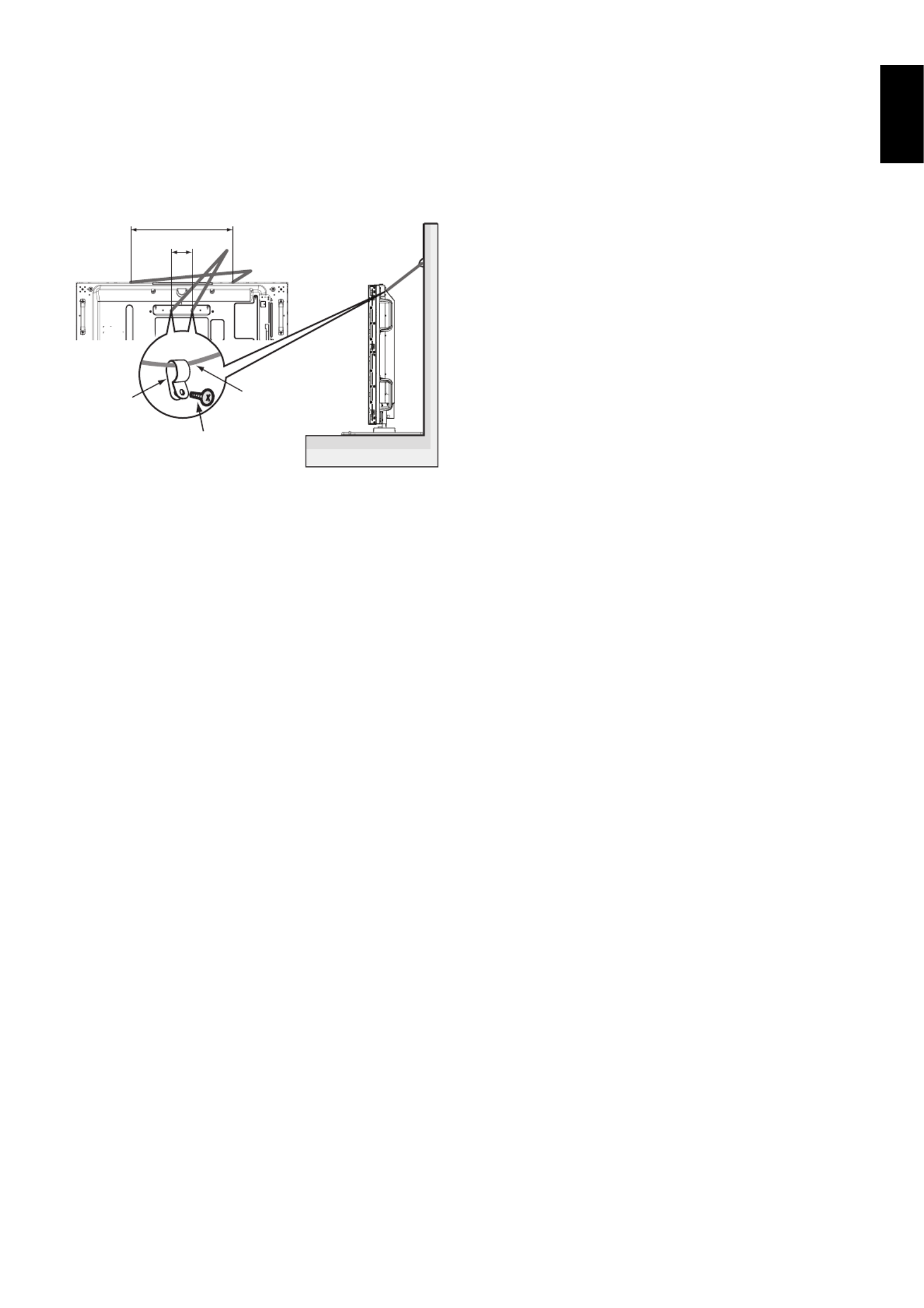
5. Prevent Tipping
When using the display with the optional table top stand
fasten the LCD to a wall using a cord or chain that can
support the weight of the monitor in order to prevent the
monitor from falling. Fasten the cord or chain to the monitor
using the provided clamps and screws.
For the X464UN/X464UNV, the clamps and screws are
included with the optional table top stand.
Screw (M4)
Cord or chain
Clamp
100 mm (X464UN/X464UNV) Screw Holes (X464UN/X464UNV)
Screw Holes (X464UN/X464UNV)
Screw Holes (X464UN/X464UNV)
Screw Holes (X464UN/X464UNV)Screw Holes (X464UN/X464UNV)
Screw Holes (X554UN/X554UNS)
Screw Holes (X554UN/X554UNS)
Screw Holes (X554UN/X554UNS)
Screw Holes (X554UN/X554UNS)Screw Holes (X554UN/X554UNS)
640 mm (X554UN/X554UNS)
Before attaching the LCD monitor to the wall, make sure that
the wall can support the weight of the monitor.
Be sure to remove the cord or chain from the wall before
moving the LCD.

English-8
Parts Name and Functions
Control Panel
쐃 POWER button ( )
Switches the power on/off. See also page 16.
쐇 MUTE button (MUTE)
Switches the audio mute ON/OFF.
쐋 INPUT button (INPUT)
Acts as SET/POINT ZOOM button within OSD menu.
(Toggle switches between [DVI], [DPORT], [HDMI], [VGA] or
[Y/Pb/Pr], [SCART]*, [VIDEO]*, [S-VIDEO]*, [DPORT2]*,
[DPORT3]*, [HDMI2]*, [RGB/HV]* or [Y/Pb/Pr2]*). These are
available input only, shown as their factory preset name.
쐏 PLUS button (+)
Acts as (+) button to increase the adjustment with OSD menu.
Increases the audio output level when the OSD menu is
turned off.
쐄 MINUS button (-)
Acts as (-) button to decrease the adjustment with OSD menu.
Decreases the audio output level when the OSD menu is
turned off.
쐂 UP button ( )
Activates the OSD menu when the OSD menu is turned-off.
Acts as button to move the highlighted area up to select
adjustment items within OSD menu.
쐆 DOWN button ( )
Activates the OSD menu when the OSD menu is turned-off.
Acts as button to move the highlighted area down to select
adjustment items within OSD menu.
쐊 EXIT button (EXIT)
Activates the OSD menu when the OSD menu is turned-off.
Acts as EXIT button within the OSD to move to previous
menu.
쐎 Remote control sensor and Power Indicator
Receives the signal from the remote control (when using the
wireless remote control). See also page 11.
Glows green when the LCD monitor is in active mode*.
Glows red when the LCD is in POWER OFF mode.
Glows amber when the monitor is in Power Save Mode.
Green and Amber blink alternately while in Power Standby
mode with the “SCHEDULE SETTINGS” function enabled.
When a component failure is detected within the monitor, the
indicator will blink red.
* If “OFF” is selected in “POWER INDICATOR” (see page 25),
LED will not light when the LCD monitor is in active mode.
Control Key Lock Mode
This control completely locks out access to all Control Key
functions. To activate the control key lock function, press
both and and hold down simultaneously for more than
3 seconds. To resume user mode, press both and and
hold simultaneously for more than 3 seconds.
*: This function depends on which option board you use.

English-9
English
Terminal Panel
Option control unit
From Option control unit
쐃 AC IN connector
Connects with the supplied power cord.
쐇 Main Power Switch
On/Off switch to turn main power ON/OFF.
쐋 EXTERNAL SPEAKER TERMINAL
To output the audio signal from AUDIO 1, DPORT and HDMI.
Red terminal is plus (+).
Black terminal is minus (-).
NOTE: This speaker terminal is for 15 W + 15 W (8 ohm) speaker.
쐏 AUDIO OUT
To output the audio signal from the AUDIO IN 1, 2, DPORT and
HDMI to an external device (stereo receiver, amplifi er, etc.).
쐄 Service port
This USB slot is for future software upgrades.
쐂 LAN port (RJ-45)
LAN connection. See page 31 and 34.
NOTE: Please give priority for use to LAN1.
쐆 AUDIO IN 1, 2
To input audio signal from external equipment such as a
computer or DVD player.
RS-232C (D-Sub 9 pin)
Connect RS-232C input from external equipment such as a PC
in order to control RS-232C functions.
쐎 REMOTE IN
Use the optional wired remote control by connecting it to your
monitor.
NOTE: Do not use this connector unless specifi ed.
쐅 VGA IN (mini D-Sub 15 pin)
To input analog RGB signals from a personal computer or
from other RGB equipment. This input can be used with an
RGB or COMPONENT source. Please select signal type in
TERMINAL SETTING. See page 27.
NOTE: When you use this connector for COMPONENT,
please use a suitable signal cable. If you have any questions,
please ask your dealer.
쐈 DisplayPort connectors
IN connector: To input DisplayPort signals.
OUT connector: To output signal which is displayed.
See page 25 VIDEO OUT SETTING.
To output signal which is displayed as a main picture when
selected PIP mode. See page 11.
쐉 HDMI IN
To input digital HDMI signals.
씈 DVI IN (DVI-D)
To input digital RGB signals from a computer or HDTV device
having a digital RGB output.
* This connector does not support analog input.
씉 Option board slot
Slot 2 and slot 3 type accessories are available.
Please contact your supplier for detailed information.
NOTE: Please contact your supplier for available option board.
씊 Remote control sensor, AMBIENT LIGHT SENSOR
and HUMAN SENSOR
Receives the signal from the Remote control.
Detects the level of ambient light, allowing the monitor to
make automatic adjustments to the brightness setting,
resulting in a more comfortable viewing experience.
Do not cover this sensor. See page 19.
Detects human presence in front of the monitor. See page 45.
씋 Kensington Lock
For security and theft prevention.
씌 Intelligent wireless data sensor
Sensor for wireless communication of the monitor information
and settings.
English-10
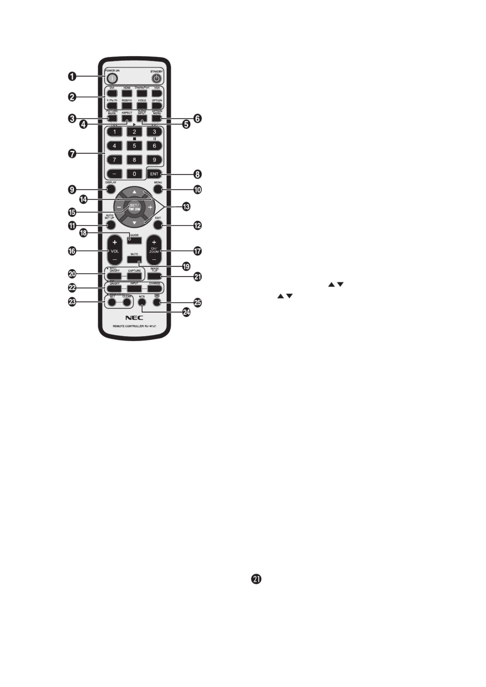
Wireless Remote Control (Optional)
쐃 POWER button
Switches the power on/standby.
쐇 INPUT button
Selects input signal.
DVI: DVI
HDMI: HDMI, HDMI2*
2
DisplayPort: DPORT, DPORT2*2, DPORT3*2
VGA: VGA
Y/Pb/Pr: Y/Pb/Pr, SCART*2, Y/Pb/Pr2*2
RGB/HV*2: RGB/HV
VIDEO*2: VIDEO, S-VIDEO
OPTION: Depends on your connection
쐋 PICTURE MODE button
Selects picture mode, [HIGHBRIGHT], [STANDARD],
[sRGB], [CINEMA], [CUSTOM1], [CUSTOM2]. See page 18.
HIGHBRIGHT: for moving images such as DVD.
STANDARD: for images.
sRGB: for text based images.
CINEMA: for movies.
CUSTOM1 and CUSTOM2: activate auto dimming
function. See page 28.
쐏 ASPECT button
Selects picture aspect, [FULL], [WIDE], [DYNAMIC], [1:1],
[ZOOM] and [NORMAL]. See page 17.
쐄 AUDIO INPUT button
Selects audio input source [IN1], [IN2], [IN3]*2, [OPTION]*2,
[HDMI], [DPORT], [HDMI2]*2, [DPORT2]*2, [DPORT3]*2.
쐂 OPTION MENU button*1
쐆 KEYPAD
Press buttons to set and change passwords, change channel
and set REMOTE ID.
쐊 ENT button*1
쐎 DISPLAY button
Turns on/off the information OSD. See page 18.
쐅 MENU button
Turns on/off the menu mode.
쐈 AUTO SET UP button
Enters auto setup menu. See page 20.
쐉 EXIT button
Returns to previous menu within OSD menu.
씈 UP/DOWN button ( / )
Acts as button to move the highlighted area up or down
to select adjustment items within OSD menu.
Small screen which adjusted “PIP” mode moves up or down.
씉 MINUS/PLUS (-/+) button
Increases or decreases the adjustment level within OSD
menu settings.
Small screen which adjusted “PIP” mode moves left or right
and increases or decreases the size.
씊 SET/POINT ZOOM button
Makes selection. Activates POINT ZOOM function when OSD
menu is not shown.
씋 VOLUME UP/DOWN button (VOL +/-)
Increases or decreases audio output level.
씌 CH/ZOOM UP/DOWN button (CH/ZOOM +/-)*
1
Increases or decreases POINT ZOOM level.
씍 GUIDE button*1
씎 MUTE button
Turns on/off mute function.
씏 STILL button
ON/OFF button: Activates/deactivates still picture mode.
STILL CAPTURE button: Captures still picture.
NOTE: This function is released when activating IMAGE
FLIP.
IMAGE FLIP button
Toggle switches between H FLIP, V FLIP, 180° ROTATE and
NONE. See page 21.
English-11
English
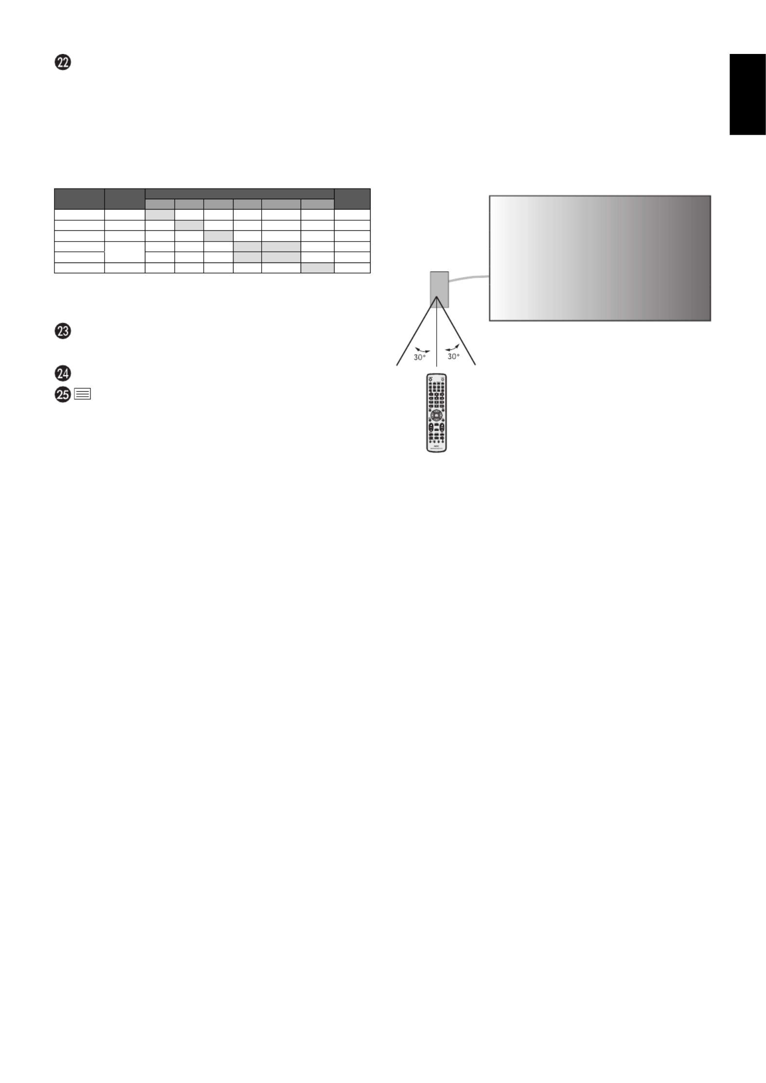
Operating Range for the Optional
Remote Control
Point the top of the remote control toward the sensor unit’s
remote control sensor in optional control kit during button
operation.
Use the remote control within a distance of about 7 m (23 ft.)
from remote control sensor or at a horizontal and vertical
angle of within 30° within a distance of about 3.5 m (10 ft.).
Caution: Important, the remote control
system may not function
when direct sunlight or strong
illumination strikes the remote
control sensor or when there is
an object in the path.
Handling the remote control
• Do not subject to strong shock.
• Do not allow water or other liquid to splash the remote
control. If the remote control gets wet, wipe it dry
immediately.
• Avoid exposure to heat and steam.
• Other than to install the batteries, do not open the remote
control.
PIP (Picture In Picture) button
ON/OFF button: Toggle switches between PIP, POP,
PICTURE BY PICTURE-ASPECT and PICTURE BY
PICTURE-FULL. See page 22.
INPUT button: Selects the “picture in picture” input signal.
CHANGE button: Replaces to the main picture and sub
picture.
NOTE: Enable to change the sub picture size by pressing
SET/POINT ZOOM button during PIP mode.
Main picture Connector Sub picture DP Out*5
DPORT*
DPORT*
DPORT*
DPORT*DPORT*
3
3
3
33
DVI
DVI
DVI
DVIDVI HDMI
HDMI
HDMI
HDMIHDMI VGA
VGA
VGA
VGAVGA
Y/Pb/Pr
Y/Pb/Pr
Y/Pb/Pr
Y/Pb/PrY/Pb/Pr
OPTION
OPTION
OPTION
OPTIONOPTION
DPORT
DPORT
DPORT
DPORTDPORT DisplayPort
DisplayPort
DisplayPort
DisplayPortDisplayPort No
No
No
NoNo Y
Y
Y
Yes
es
es
esYes Y
Y
Y
Yes
es
es
esYes Y
Y
Y
Yes
es
es
esYes Y
Y
Y
Yes
es
es
esYes Y
Y
Y
Yes
es
es
esYes DPORT
DPORT
DPORT
DPORTDPORT
DVI
DVI
DVI
DVIDVI DVI-D
DVI-D
DVI-D
DVI-DDVI-D Y
Y
Y
Yes
es
es
esYes No
No
No
NoNo Y
Y
Y
Yes
es
es
esYes Y
Y
Y
Yes
es
es
esYes Y
Y
Y
Yes
es
es
esYes Y
Y
Y
Yes
es
es
esYes DVI
DVI
DVI
DVIDVI
HDMI
HDMI
HDMI
HDMIHDMI HDMI
HDMI
HDMI
HDMIHDMI Y
Y
Y
Yes
es
es
esYes Y
Y
Y
Yes
es
es
esYes No
No
No
NoNo Y
Y
Y
Yes
es
es
esYes Y
Y
Y
Yes
es
es
esYes Y
Y
Y
Yes
es
es
esYes HDMI 1
HDMI 1
HDMI 1
HDMI 1HDMI 1
VGA
VGA
VGA
VGAVGA D-Sub*
D-Sub*
D-Sub*
D-Sub*D-Sub*4
4
4
44 Y
Y
Y
Yes
es
es
esYes Y
Y
Y
Yes
es
es
esYes Y
Y
Y
Yes
es
es
esYes No
No
No
NoNo No
No
No
NoNo Y
Y
Y
Yes
es
es
esYes -
-
-
--
Y/Pb/Pr
Y/Pb/Pr
Y/Pb/Pr
Y/Pb/PrY/Pb/Pr Y
Y
Y
Yes
es
es
esYes Y
Y
Y
Yes
es
es
esYes Y
Y
Y
Yes
es
es
esYes No
No
No
NoNo No
No
No
NoNo Y
Y
Y
Yes
es
es
esYes -
-
-
--
OPTION
OPTION
OPTION
OPTIONOPTION Option
Option
Option
OptionOption Y
Y
Y
Yes
es
es
esYes Y
Y
Y
Yes
es
es
esYes Y
Y
Y
Yes
es
es
esYes Y
Y
Y
Yes
es
es
esYes Y
Y
Y
Yes
es
es
esYes No
No
No
NoNo OPTION
OPTION
OPTION
OPTIONOPTION
*3:
*3:
*3:
*3: When VIDEO OUT SETTING is ON, DPORT cannot be selected as the sub picture.
When VIDEO OUT SETTING is ON, DPORT cannot be selected as the sub picture.
When VIDEO OUT SETTING is ON, DPORT cannot be selected as the sub picture.
When VIDEO OUT SETTING is ON, DPORT cannot be selected as the sub picture.*3: When VIDEO OUT SETTING is ON, DPORT cannot be selected as the sub picture.
*4:
*4:
*4:
*4: If VGA or Y/Pb/Pr is selected as the main picture, DP
If VGA or Y/Pb/Pr is selected as the main picture, DP
If VGA or Y/Pb/Pr is selected as the main picture, DP
If VGA or Y/Pb/Pr is selected as the main picture, DP out is disabled even when
out is disabled even when
out is disabled even when
out is disabled even when *4: If VGA or Y/Pb/Pr is selected as the main picture, DP out is disabled even when
VIDEO OUT SETTING is ON.
VIDEO OUT SETTING is ON.
VIDEO OUT SETTING is ON.
VIDEO OUT SETTING is ON. VIDEO OUT SETTING is ON.
*5:
*5:
*5:
*5: DP out can output signal only when VIDEO OUT SETTING is ON.
DP out can output signal only when VIDEO OUT SETTING is ON.
DP out can output signal only when VIDEO OUT SETTING is ON.
DP out can output signal only when VIDEO OUT SETTING is ON.*5: DP out can output signal only when VIDEO OUT SETTING is ON.
REMOTE ID button
Activates REMOTE ID function.
MTS button*1
button*1
Activates closed captioning.
NOTE: VIDEO* 2
, S-VIDEO*2 inputs only.
*1: This button’s action depends on which option board you use.
Refer to the option board’s manual for further information.
*2: This function depends on which option board you use.

English-12
1. Determine the installation location
CAUTION: Installing your LCD monitor must be done by a
qualifi ed technician. Contact your dealer for more
information.
CAUTION:
MOVING OR INSTALLING THE LCD MONITOR
MUST BE DONE BY TWO OR MORE PEOPLE.
Failure to follow this caution may result in injury if
the LCD monitor falls.
CAUTION: Do not mount or operate the monitor upside
down, face up or face down.
CAUTION: This LCD has a temperature sensor and cooling
fan, including a fan for the option board.
If the LCD becomes too hot, the cooling fan will
turn on automatically.
The option board’s fan is active although the
temperature is lower than normal operating
temperature for cooling the option board. If the
LCD becomes overheated while the cooling fan
is running, a “Caution” warning will appear. If the
“Caution” warning appears, discontinue use and
allow the unit to cool. Using the cooling fan will
reduce the likelihood of early circuit failure and
may help reduce image degradation and “Image
Persistance”.
If the LCD is used in an enclosed area or if the
LCD panel is covered with a protective screen,
please check the inside temperature of the
monitor by using the “HEAT STATUS” control
in the OSD (see page 25). If the temperature is
higher than the normal operating temperature,
please turn the cooling fan to ON within the FAN
CONTROL menu within the OSD (see page 25).
IMPORTANT: Lay the protective sheet, which was wrapped
around the LCD monitor when it was
packaged, beneath the LCD monitor so as not
to scratch the panel.
2. Install the remote control (Optional)
batteries
The remote control is powered by two 1.5V AAA batteries.
To install or replace batteries:
A. Press and slide to open the cover.
B. Align the batteries according to the (+) and (–) indications
inside the case.
C. Replace the cover.
CAUTION: Incorrect usage of batteries can result in leaks or
bursting.
NEC recommends the following battery use:
• Place “AAA” size batteries matching the (+) and (-) signs
on each battery to the (+) and (-) signs of the battery
compartment.
• Do not mix battery brands.
• Do not combine new and old batteries. This can shorten
battery life or cause liquid leakage of batteries.
• Remove dead batteries immediately to prevent battery
acid from leaking into the battery compartment.
• Do not touch exposed battery acid, it may injure skin.
NOTE: If you do not intend to use the Remote Control for
a long period of time, remove the batteries.
3. Connect external equipment
(See pages 14 and 15)
• To protect the external equipment; turn off the main power
before making connections.
• Refer to your equipment user manual for further
information.
NOTE: Do not connect/disconnect cables when turning
on the monitor or other external equipment as this
may result in a loss of the monitor image.
4. Connect the supplied power cord
• The equipment should be installed close to an easily
accessible power outlet.
• Please fasten power cord to the LCD monitor by attaching
the screw and clamp.
• Fully insert the prongs into the power outlet socket.
A loose connection may cause image degradation.
NOTE: Please refer to the “Safety Precautions and
Maintenance” section of this manual for proper
selection of AC power cord.
Screw
Clamp
Setup

English-13
English
5. Switch on the power of all the attached
external equipment
When connected with a computer, switch on the power of the
computer fi rst.
6. Operate the attached external equipment
Display the signal from the desired input source.
7. Adjust the sound
Make volume adjustments when required.
8. Adjust the screen (See pages 20 and 21)
Make adjustments of the screen display position when
necessary.
9. Adjust the image (See page 20)
Make adjustments such as backlight or contrast when
required.
10. Recommended Adjustments
To reduce the risk of the “Image Persistence”, please adjust
the following items based on the application being used:
“SCREEN SAVER”, “SIDE BORDER COLOR” (See page 25)
“DATE & TIME”, “SCHEDULE SETTINGS” (See page 22).
It is recommended that the “FAN CONTROL” setting
(See page 25) be turned to ON also.

English-14
Connections
NOTE: Do not connect/disconnect cables when turning on the monitor or other external equipment as this may result in a
loss of the monitor image.
NOTE: Use an audio cable without a built-in resistor. Using an audio cable with a built-in resistor turns down the sound.
Before making connections:
* First turn off the power of all the attached equipment and make connections.
* Refer to the user manual included with each separate piece of equipment.
Wiring Diagram
Solid lines = video signal
Dotted lines = audio signal
Stereo Amplifi er
Second monitor*
Computer (Analog) Computer (Digital)
DVD Player
*: Multiple monitors that are daisy-chained have a limit to the connectable monitors.
Connected
equipment
Connecting
terminal Setting in terminal mode Input signal name Connecting
audio terminal
Input button
in remote control
AV
DisplayPort - DP DPORT DisplayPort
DVI (DVI-D) DVI-HD DVI AUDIO IN1/IN2 DVI
HDMI RAW/EXPAND*1HDMI HDMI HDMI
VGA (D-Sub) D-SUB MODE RGB VGA AUDIO IN1/IN2 RGB/HV
VGA (D-Sub) D-SUB MODE COMPONENT COMPONENT AUDIO IN1/IN2 Y/Pb/Pr
Option - OPTION OPTION OPTION
PC
DisplayPort - DP DPORT DisplayPort
DVI (DVI-D) DVI-PC DVI AUDIO IN1/IN2 DVI
HDMI RAW/EXPAND*1HDMI HDMI HDMI
VGA (D-Sub) - VGA AUDIO IN1/IN2 RGB/HV
Option - OPTION OPTION OPTION
*1: depend on signal type.

English-15
English
Connecting a Personal Computer
Connecting your computer to your LCD monitor will enable you to display your computer’s screen image.
Some video cards may not display an image correctly.
Your LCD monitor displays proper image by adjusting the factory preset timing signal automatically.
<Typical factory preset signal timing>
Resolution Scanning frequency Remarks
Horizontal Vertical
640 x 480 31.5 kHz 60 Hz
800 x 600 37.9 kHz 60 Hz
1024 x 768 48.4 kHz 60 Hz
1280 x 768 48 kHz 60 Hz
1360 x 768 48 kHz 60 Hz
1280 x 1024 64 kHz 60 Hz
1600 x 1200 75 kHz 60 Hz Compressed image
1920 x 1080 67.5 kHz 60 Hz Recommended resolution
• If you use with a Macintosh PowerBook, set “Mirroring” to Off on your PowerBook.
Refer to your Macintosh’s owner’s manual for more information about your computer’s video output requirements and any
special identifi cation or confi guration your monitor’s image and monitor may require.
• Input TMDS signals conforming to DVI standards.
• To maintain display quality, use a cable that conforms to DVI standards.
Connecting a DVD Player or Computer with HDMI out
• Please use an HDMI cable with HDMI logo.
• It may take a moment for the signal to appear.
• Some video cards or drivers may not display an image correctly.
• When you use a computer with HDMI out, please set OVER SCAN to “OFF” (see page 27).
Connecting a Computer with DisplayPort
• Please use DisplayPort cable with DisplayPort compliance logo.
• It may take a moment for the signal to appear.
• Please note that when connecting a DisplayPort cable to a component with a signal conversion adapter, an image may not
appear.
• Select DisplayPort cables feature a locking function. When removing this cable, hold down the top button to release the lock.

English-16
Basic Operation
Power ON and OFF Modes
The LCD monitor power indicator will turn green while powered on and will turn red or amber while powered off.
NOTE: The Main Power Switch must be in the ON position in order to power up the monitor using the remote control or the
Power Button.
Main Power Switch
ON
OFF
Power Button
Using the optional remote control

English-17
English
Picture Aspect
DVI, VGA, RGV/HV*4, DPORT, DPORT2*4, DPORT3*4
FULL 1:1 ZOOM NORMAL
HDMI, Y/Pb/Pr, SCART*4, VIDEO*4, S-VIDEO*4, HDMI2*4, Y/Pb/Pr2*4
FULL WIDE DYNAMIC 1:1 ZOOM NORMAL
Aspect ratio
of image Unchanged view*3Recommended selection
for picture aspect*3
4:3
NORMAL
DYNAMIC
Squeeze
FULL
Letterbox
WIDE
*3 Grey areas indicate unused portions of the screen.
NORMAL: Displays the aspect ratio the same as it is sent
from the source.
FULL: Fills entire screen.
WIDE: Expands a 16:9 letter box signal to fi ll entire screen.
DYNAMIC: Expands a 4:3 pictures to fi ll the entire screen
with non-linearity. Some of the outside image area will be cut
off due to expansion.
1:1: Displays the image in a 1 by 1 pixel format.
ZOOM
The image can be expanded beyond the active display area.
The image which is outside of active display area is not
shown.
ZOOM
ZOOM
*4: This function depends on which option board you use.
Power Indicator
Mode Status Indicator Light
Power ON Green*1
Power OFF and Power Save “AUTO
POWER STANDBY”
Power consumption under 0.5 W
Red
Power Save “AUTO POWER SAVE”
Power consumption under 2.5 W*2
Amber
Power Standby when “SCHEDULE
SETTINGS” enabled
Green and Amber blink alternately
Diagnosis (Detecting failure) Red Blinking
(See Troubleshooting page 46)
*1 If “OFF” is selected in POWER INDICATOR (page 25), the LED will not light when the
LCD monitor is in active mode.
*2 Without any option, with factory settings.
Using Power Management
The LCD monitor follows the VESA approved DPM Display
Power Management function.
The power management function is an energy saving
function that automatically reduces the power consumption
of the display when the keyboard or the mouse has not been
used for a fi xed period.
The power management feature on your new display has
been set to the “AUTO POWER SAVE” mode. This allows
your display to enter a Power Saving Mode when no signal is
applied. This could potentially increase the life and decrease
the power consumption of the display.
NOTE: Depending on the PC and video card used, this
function may not operate.
NOTE: The monitor automatically goes into OFF at the
preset time period after signal is lost.
Selecting a video source*4
To view a video source:
Use the input button to set [VIDEO], [S-VIDEO].
Use the COLOR SYSTEM menu to set [AUTO], [NTSC],
[PAL], [SECAM], [PAL60], [4.43NTSC], according to your
video format.

English-18
Information OSD
The Information OSD provides information such as: Input Source, Picture Size, etc.
Press the DISPLAY button on the remote to bring up the Information OSD.
쐃 Input Name
쐇 Audio input mode
쐋 Picture aspect
쐏 Input Signal Information
Sub picture information
Picture Mode
DVI, VGA, RGB/HV*, DPORT, DPORT2*, DPORT3*
STANDARD sRGB CUSTOM1 CUSTOM2 HIGHBRIGHT
HDMI, Y/Pb/Pr, SCART*, VIDEO*, S-VIDEO*, HDMI2*, Y/Pb/Pr2*
STANDARD CINEMA CUSTOM1 CUSTOM2 HIGHBRIGHT
*: This function depends on which option board you use.

English-19
English
OSD (On-Screen-Display) Controls
NOTE: Some functions may not be available depending on the model or optional equipment.
PICTURE MODE
Goto Adjustment
Select Return Close
70
50
50
50
50
50
THANK YOU FOR SAVING
THE ENVIRONMENT.
CARBON FOOTPRINT 86.0 %
Input source
Main Menu Icons
Main Menu Item
Sub Menu
Key Guide
Adjustment Settings
Remote Control
Press UP or DOWN
button to select
sub-menu.
Press SET/POINT
ZOOM.
Press UP or DOWN,
PLUS or MINUS to select
the function or setting to
be adjusted.
Press MENU or EXIT.
Press UP or DOWN
button to select.
Press INPUT button
to decide.
Press UP or DOWN, PLUS
or MINUS button to select.
Press EXIT
Control Panel
OSD screen

English-20
Setting Default
PICTURE
BACKLIGHT Adjusts the overall image and background brightness. Press + or - to adjust.
NOTE: When MODE1 or MODE2 is selected in ROOM LIGHT SENSING, this function cannot be
changed.
70
CONTRAST Adjusts the image brightness in relationship to the input signal. Press + or - to adjust.
NOTE: When sRGB is selected in picture mode, this function cannot be changed.
50
SHARPNESS Adjusts the crispness of the image. Press + or - to adjust. 50*2
BRIGHTNESS Adjusts the image brightness in relationship to the background. Press + or - to adjust.
NOTE: When sRGB is selected in picture mode, this function cannot be changed.
50
HUE Adjusts the hue of the screen. Press + or - to adjust.
NOTE: When sRGB is selected in picture mode, this function cannot be changed.
50
COLOR Adjusts the color depth of the screen. Press + or - to adjust.
NOTE: When sRGB is selected in picture mode, this function cannot be changed.
50*2
COLOR TEMPERATURE Adjusts the color temperature of the entire screen. A low color temperature will make the screen
reddish. A high color temperature will make the screen bluish. If TEMPERATURE needs further
adjustment, the individual R/G/B/ levels of the white point can be adjusted. To adjust the R/G/B
levels, CUSTOM must be showing as the COLOR TEMP selection.
NOTE: When sRGB is selected in picture mode, predefi ned 6500k is set so it cannot be changed.
When PROGRAMMABLE1, PROGRAMMABLE2 or PROGRAMMABLE3 is selected in GAMMA
CORRECTION, this function cannot be changed.
10000K
COLOR CONTROL Adjusts the hue of the Red, Yellow, Green, Cyan, Blue and Magenta.
NOTE: When sRGB is selected in picture mode, this function cannot be changed.
When INPUT2 of SUPER is selected in INPUT CHANGE and displayed, this function cannot be
changed.
0
GAMMA CORRECTION Select a display gamma for best picture quality.
NOTE: When sRGB is selected in picture mode, this function cannot be changed.
PROGRAMMABLE1
(except sRGB
setting)
NATIVE Gamma correction is handled by the LCD panel.
2.2 Typical display gamma for use with a PC.
2.4 Good for video (DVD, etc.)
S GAMMA Special gamma for certain types of movies. Raises the dark parts and lowers the light parts of the
image (S-Curve).
DICOM SIM. DICOM GSDF curve simulated for LCD type.
PROGRAMMABLE1, 2, 3
A programmable gamma curve can be loaded using NEC optional software.
MOVIE SETTINGS NOTE: When INPUT2 of SUPER is selected in INPUT CHANGE and displayed, this function
cannot be changed.
NOISE REDUCTION* 1
VIDEO, S-VIDEO inputs only
Adjusts the amount of noise reduction. Press + or - to adjust. 0*
2
TELECINE
HDMI, Y/Pb/Pr, SCART*
1
, VIDEO*
1
,
S-VIDEO*
1
, HDMI2*
1
, Y/Pb/Pr2*
1
inputs only
Automatically senses the sources frame rate for optimal picture quality. AUTO*
2
ADAPTIVE CONTRAST
HDMI, Y/Pb/Pr, SCART*
1
, VIDEO*
1
,
S-VIDEO*
1
, HDMI2*
1
, Y/Pb/Pr2*
1
inputs only
Sets the level of adjustment for dynamic contrast. OFF
PICTURE MODE Selects picture mode, [HIGHBRIGHT], [STANDARD], [sRGB], [CINEMA], [CUSTOM1] or
[CUSTOM2]. See page 18.
STANDARD
RESET Resets the following settings within the PICTURE menu back to factory setting: BACKLIGHT,
CONTRAST, SHARPNESS, BRIGHTNESS, HUE, COLOR, COLOR TEMPERATURE,
COLOR CONTROL, GAMMA CORRECTION, MOVIE SETTINGS.
-
ADJUST
AUTO SETUP
VGA, RGB/HV*1
inputs only
Automatically adjusts Screen Size, H position, V position, Clock, Phase and White Level. -
AUTO ADJUST
VGA, RGB/HV*1
inputs only
H Position, V Position and Phase are adjusted automatically when new timing is detected. OFF
H POSITION
All inputs except DVI, HDMI, DPORT
Controls the horizontal position of the image within the Display area of the LCD.
Press + to move right. Press - to move left.
-
V POSITION
All inputs except DVI, HDMI, DPORT
Controls the vertical position of the image within the Display area of the LCD.
Press + to move up. Press - to move down.
-
CLOCK
VGA, RGB/HV*1
inputs only
Press + to expand the width of the image on the right of the screen.
Press - to narrow the width of the image on the left.
-
*1: This function depends on which option board you use.
*2: Depends on signal input.

English-21
English
PHASE
VGA, RGB/HV*1, Y/Pb/Pr, SCART*1
, Y/Pb/Pr2*1
inputs only
Adjusts the visual “noise” on the image. -
H RESOLUTION
VGA, RGB/HV*1 inputs only
Adjusts the horizontal size of the image. -
V RESOLUTION
VGA, RGB/HV*1 inputs only
Adjusts the vertical size of the image. -
INPUT RESOLUTION
VGA, RGB/HV*1 inputs only
If there is a problem with signal detection, this function forces the monitor to display the signal at
the desired resolution. After selection, execute “AUTO SETUP” if required.
If no problem is detected, the only available option will be “AUTO”.
AUTO
ASPECT Select the aspect ratio of the screen image.
NOTE: When the ASPECT is DYNAMIC, WIDE or ZOOM, the image will be changed FULL
image before IMAGE FLIP, then start to IMAGE FLIP.
When the ASPECT is DYNAMIC or ZOOM, the image will be changed FULL image before TILE
MATRIX, then start to TILE MATRIX. After TILE MATRIX, the ASPECT will be returned previous
ASPECT or set ASPECT during TILE MATRIX.
When the ASPECT is DYNAMIC or ZOOM, the image will be changed FULL image before POINT
ZOOM, then start to POINT ZOOM. After POINT ZOOM, the ASPECT will be returned previous
ASPECT. When the ASPECT is changed during POINT ZOOM, DYNAMIC and ZOOM will be
FULL image.
FULL
NORMAL Displays the aspect ratio the same as it is sent from the source. -
FULL Fills entire screen. -
WIDE Expands a 16:9 letter box signal to fi ll entire screen. -
DYNAMIC Expands a 4:3 pictures to fi ll the entire screen with non-linearity. Some of the outside image area
will be cut off due to expansion. TILE MATRIX becomes invalid.
-
1:1 Display the image in a 1 by 1 pixel format. (If the input resolution is higher than a 1920 x 1080
resolution, the image will be scaled down to fi t the screen). TILE MATRIX becomes invalid.
-
ZOOM The image can be expanded/reduced.
NOTE: The expanded image which is outside of active display area is not shown. The reduced
image may have some image degradation.
-
ZOOM Maintains the aspect ratio while zooming. -
HZOOM Amount of horizontal zoom.
VZOOM Amount of vertical zoom.
H POS Horizontal position.
V POS Vertical position.
IMAGE FLIP NOTE: OVER SCAN is disabled when IMAGE FLIP is selected.
When the ASPECT is DYNAMIC, WIDE or ZOOM, the image will be changed FULL image before
IMAGE FLIP, then start to IMAGE FLIP.
When selecting IMAGE FLIP except for NONE, following functions are released: PIP MODE,
TILE MATRIX, SUPER in INPUT CHANGE, STILL, POINT ZOOM.
-
IMAGE FLIP Display the inverse image right-left, up-down or rotation.
Press + or - to select.
NONE
NONE Normal mode. -
H FLIP The image inverts right-left. -
V FLIP The image inverts up-down. -
180° ROTATE The image rotates 180 degrees. -
OSD FLIP Determines the OSD display direction.
If “ON” is selected, OSD will invert depending on the image.
OFF
RESET Resets “ADJUST” settings back to factory settings. -
AUDIO
VOLUME Increases or decreases output volume level. 40
BALANCE Select “STEREO” or “MONO” of audio output.
If you select “STEREO”, adjust the balance of L/R volume.
Press + button to move the stereo sound image to right.
Press - button to move the stereo sound image to left.
CENTER,
STEREO
TREBLE To accentuate or reduce the high frequency sound.
Press + button to increase TREBLE sound.
Press - button to decrease TREBLE sound.
0
*1: This function depends on which option board you use.

English-22
BASS To accentuate or reduce the low frequency sound.
Press + button to increase BASS sound.
Press - button to decrease BASS sound.
0
SURROUND Artifi cial surround sound.
NOTE: Audio out is disabled when this function is set to ON.
OFF
PIP AUDIO Selects source of PIP audio. MAIN AUDIO
LINE OUT Selecting “VARIABLE” enables control of the line out level with the VOLUME button.
NOTE: Audio out is disabled when this function is set to ON.
FIXED
AUDIO INPUT Selects audio input source [IN1], [IN2], [IN3]*1, [OPTION]*1, [HDMI], [DPORT], [HDMI2]*1,
[DPORT2]*1, [DPORT3]*1.
Depend on
signal input
AUDIO DELAY Enables to set the delay time to output the audio. DELAY TIME can be set between 0 and
100 milliseconds. “ON” activates this function.
ON,
37 MSEC.
RESET Resets “AUDIO” options back to factory settings except VOLUME. -
SCHEDULE
OFF TIMER Sets the monitor to power off after a length of time.
A time between 1 to 24 hours is available.
OFF
SCHEDULE SETTINGS Creates a working schedule for the monitor to use. -
SCHEDULE LIST List of schedules. -
DATE & TIME Sets the date, time, and daylight saving region. Date & time must be set in order for the
“SCHEDULE” function to operate. See page 29.
YEAR Confi gures the year for the real-time clock. -
MONTH Confi gures the month for the real-time clock. -
DAY Confi gures the day for the real-time clock. -
TIME Confi gures the time for the real-time clock. -
DAYLIGHT SAVING Confi gures daylight savings on or off. OFF
RESET Resets the following settings within the SCHEDULE menu back to factory setting: OFF TIMER,
SCHEDULE SETTINGS.
-
PIP
KEEP PIP MODE Allows the monitor to remain in “PIP” and “TEXT TICKER” mode after powering off.
When Power is returned, PIP and TEXT TICKER appear without having to enter the OSD.
OFF
PIP MODE Selects Picture-in-Picture mode.
NOTE: This function is released when selecting IMAGE FLIP except for NONE.
OFF
OFF Normal mode.
PIP Picture in Picture mode.
POP Picture out Picture mode.
PICTURE BY PICTURE-
ASPECT
Picture by picture (split screen) mode, with keep aspect.
PICTURE BY PICTURE
-
FULL
Picture by picture (split screen) mode, with full screen.
SUB INPUT Selects sub picture input signal. Depends on
signal input
PIP SIZE Determines the size of the sub-picture used in Picture-in-Picture (PIP) mode.
Press the SET/POINT ZOOM button to adjust. Press + or CH+ to expand. Press - or CH- to
reduce.
It is also possible to change the sub-picture size by pressing the SET/POINT ZOOM button when
the sub-picture is shown.
37
PIP POSITION Determines the location where the PIP appears on the screen. X = 95, Y = 92
ASPECT Selects sub picture aspect, [FULL], [NORMAL] and [WIDE]. See page 17. FULL
TEXT TICKER OFF
MODE Enables Text Ticker and allows you to set Horizontal or Vertical direction.
POSITION Selects the location of the Text Ticker on the screen.
SIZE Determines the size of the Text Ticker in relationship to the overall screen size.
*1: This function depends on which option board you use.

English-23
English
BLEND Sets the transparency of the Text Ticker (0: transparent, 100: opaque).
DETECT Enables auto-detection of the Text Ticker.
FADE IN Enables fade-in of the text ticker.
RESET Resets PIP options back to factory settings except SUB INPUT and ASPECT. -
OSD
LANGUAGE Select the language used by the OSD. ENGLISH
(Depends on
destination)
ENGLISH
DEUTSCH
FRANÇAIS
ITALIANO
ESPAÑOL
SVENSKA
РУССКИЙ
MENU DISPLAY TIME Turns off the OSD after a period of inactivity. The preset choices are 10-240 seconds. 30 SEC.
OSD POSITION Determines the location where the OSD appears on the screen.
X = 128, Y = 225
UP
DOWN
RIGHT
LEFT
INFORMATION OSD Selects whether the information OSD is displayed or not. The information OSD will be displayed
when the input signal or source changes. The information OSD will also give a warning when
there is no-signal or the signal is out-of range.
An interval between 3 to 10 seconds for the Information OSD to appear is available.
ON, 3 SEC.
MONITOR INFORMATION Indicates the model and serial number of your monitor and fi rmware version.
CARBON SAVINGS: Display the estimated carbon saving information in kg-CO2. The carbon
footprint factor in the carbon saving calculation is based on the OECD (2008 Edition).
CARBON USAGE: Display the estimated carbon usage information in kg-CO2. This is the
arithmetic estimation, not actual measurement value. This estimation is based without any
options.
-
OSD TRANSPARENCY Set the transparency of the OSD. OFF
OSD ROTATION Determines the OSD display direction between landscape and portrait. LANDSCAPE
LANDSCAPE Display the OSD with landscape mode.
PORTRAIT Display the OSD with portrait mode.
INPUT NAME You can create a name for the INPUT currently being used.
Max: 8 characters, including Space, A-Z, 0-9, and some symbols.
-
MEMO Sets a title and message via HTTP server. See page 42. -
RESET Resets the following settings within the OSD menu back to factory setting:
MENU DISPLAY TIME, OSD POSITION, INFORMATION OSD, OSD TRANSPARENCY.
-
MULTI DISPLAY
ID CONTROL Sets the monitor ID number from 1-100 and group ID from A-J. DETECTED MONITORS shows
the number of all monitors which follow in the chain with LAN.
NOTE: Group ID is made of multiple selections.
1
AUTO ID When “YES” is selected, monitor ID numbers are set automatically in all monitors which follow in
the chain with LAN.
NOTE: All monitors which follow in the chain with LAN should be ON. When executing this
function while in standby mode or power save mode, “LAN POWER” should be ON.
NO
AUTO ID RESET Resets monitor ID number of all monitors which follow in the chain with LAN.
NOTE: AUTO ID RESET should be done when changes the number of monitors which follow in
the chain with LAN.
NO

English-24
IR LOCK SETTINGS Prevents the monitor from being controlled by the wireless remote control.
When ACTIVATE is selected, all the settings are activated.
NOTE: IR LOCK SETTINGS is a function intended only to the wireless remote control buttons.
This function does not lock out access to all buttons at the back of the monitor. To return to
normal operation, press the “DISPLAY” button on the remote control for 5 seconds.
UNLOCK
MODE SELECT Selects the mode UNLOCK, ALL LOCK or CUSTOM LOCK.
UNLOCK All buttons on the remote control are available for normal operations.
ALL LOCK Locks all remote control buttons.
CUSTOM LOCK Selects which buttons to be locked from POWER, VOLUME, and INPUT button.
Except for CUSTOM LOCK settings, other buttons on the remote control are locked.
POWER: When LOCK is selected, POWER button is locked.
VOLUME: When UNLOCK is selected, sets minimum and maximum volume between VOL.0 to
VOL.100.
VOLUME (+) button and VOLUME (-) buttons are only available from the minimum
volume to the maximum volume you set.
When LOCK is selected, VOLUME (+) button and VOLUME (-) buttons are locked.
INPUT: When UNLOCK is selected, choose up to three buttons from DVI, DisplayPort, VGA,
HDMI, Y/Pb/Pr, VIDEO* 1, S-VIDEO*1, OPTION*1 which you prefer to be unlocked.
The unselected buttons are locked. When LOCK is selected, all INPUT buttons are
locked.
TILE MATRIX Allows one image to be expanded and displayed over multiple screens (up to 100) through a
distribution amplifi er.
NOTE: Low resolution is not suitable for tiling to a large number of monitors. You can operate
without a distribution amplifi er at a lower number of screens.
This function is released when selecting IMAGE FLIP except for NONE.
When “DYNAMIC” or “ZOOM” is selected in ASPECT while executing TILE MATRIX, the setting
will be applied after completing of TILE MATRIX.
H MONITORS Number of monitors arranged horizontally. 1
V MONITORS Number of monitors arranged vertically. 1
POSITION Select which section of the tiled image to be displayed on the monitor. 1
TILE COMP Turns the TILE COMP feature on. NO
TILE MATRIX ENABLE Enables Tile Matrix. NO
FRAME COMP Sets the tiled image timing to be displayed on the monitor. Large number makes large infl uence
to displayed image.
NOTE: If FRAME COMP is set to AUTO or MANUAL, V SCAN REVERSE is not available.
The image may be distorted when turning the power on or changing the settings.
NONE
NONE FRAME COMP is not available.
AUTO Sets display timing to vertical direction of all monitors automatically.
MANUAL Sets display timing to individual monitor.
V SCAN REVERSE*2Reverse scanning image direction. Normal scanning direction is top to bottom.
NOTE: If V SCAN REVERSE is set to AUTO or MANUAL, FRAME COMP is not available.
NONE
NONE V SCAN REVERSE is not available.
AUTO Sets automatically calculated image scanning direction to all monitors.
MANUAL Sets scanning direction to individual monitor.
NON REVERSE Sets normal scanning direction and delays 1 frame display image timing.
REVERSE Reverse scanning direction to individual monitor.
TILE MATRIX MEM When “INPUT” is selected, TILE MATRIX setting is applied to each signal input. COMMON
AUTO TILE MATRIX
SETUP
Allows auto setting of multiple screens by inputting the number of monitors arranged horizontally
and vertically on the primary monitor. Following settings are set automatically: MONITOR
ID, TILE MATRIX, TILE MATRIX MEM, Input Signal, VIDEO OUT SETTING, DisplayPort in
TERMINAL SETTING.
NOTE: All monitors which follow in the chain with LAN should be ON. When executing this
function while in standby mode or power save mode, “LAN POWER” should be set to ON.
AUTO ID will be automatically executed. When you use this function, it is recommended that
monitors are chained by DisplayPort cable.
Example of installation via LAN:
H MONITORS 3
V MONITORS 3
Primary monitor
DEACTIVATE
*1: This function depends on which option board you use.
*2: Except for X554UNS.
English-25
English
POWER ON DELAY Adjusts the delay time between being in “standby” mode and entering “power on” mode.
DELAY TIME “POWER ON DELAY” can be set between 0 and 50 seconds. 0 SEC.
LINK TO ID When “ON” selected, delay time is linked with Monitor ID. It takes more time as larger ID number. OFF
VIDEO OUT SETTING Enables the signal output from DPORT. See also page 27 “DisplayPort” in TERMINAL SETTING.
NOTE: When VGA or Y/Pb/Pr is selected as the main picture, nothing will be output from DPORT.
When this function is ON, DPORT cannot be selected as the sub picture. When this function is
ON, INPUT CHANGE is limited to be NORMAL or QUICK. When this function is ON and DPORT
is selected as the main picture, PIP CHANGE button of remote control (see page 11) is disabled.
ON
POWER INDICATOR Turns ON or OFF the LED located at the back of the monitor.
If “OFF” is selected, LED will not light when the LCD monitor is in active mode.
ON
SETTING COPY In a daisy chain scenario, select the OSD menu categories that you want to copy over to the
other monitor.
NOTE: When you use this function, monitors should be daisy chained by LAN. This function
resets to default when power is off. This function has a limit depending on the cable you use.
NO
COPY START Select “YES” and press the SET button to start copying.
ALL INPUT All input terminals settings are copied when you select this item. Default is off.
RESET Resets “MULTI DISPLAY” options back to factory settings except for POWER ON DELAY and
VIDEO OUT SETTING.
-
DISPLAY PROTECTION
POWER SAVE Sets how long the monitor waits to go into power save mode after the signal is lost.
NOTE: When connecting DVI, the video card might not stop sending the digital data even
though the image might have disappeared. If this occurs the monitor will not switch into power
management mode. POWER SAVE is disabled when AUTO OFF or CUSTOM is selected in
HUMAN SENSING.
AUTO
STANDBY
AUTO POWER SAVE The monitor automatically goes into OFF at the preset time period after signal is lost.
The monitor will return to normal mode when signal is restarted.
-
AUTO STANDBY The monitor automatically goes into OFF at the preset time period after signal is lost.
Press the power button to return to normal mode.
-
DISABLE The monitor will not goes into OFF after signal is lost. -
HEAT STATUS Displays status of the FAN, BACKLIGHT and TEMPERATURE. -
FAN CONTROL Cooling fan reduces the temperature of the display to protect from overheating.
If “AUTO” is selected, you can adjust the start temperature of the cooling fan and fan speed.
AUTO, HIGH
SCREEN SAVER Use the SCREEN SAVER function to reduce the risk of Image Persistence.
GAMMA The display gamma is changed and fi xed when “ON” is selected. OFF
BACKLIGHT The brightness of backlight is decreased when “ON” is selected.
NOTE: Do not select this function when ROOM LIGHT SENSING is MODE1 or MODE2.
OFF
MOTION The screen image is slightly expanded and moves in 4 directions (UP, DOWN, RIGHT, LEFT) at
user determined intervals. You can set interval time and zooming ratio.
This function is disabled when PIP, STILL, TEXT TICKER or TILE MATRIX are enabled.
OFF
SIDE BORDER COLOR Adjusts the color of the side borders when a 4:3 image is displayed.
Press + button, the bar will become lighter.
Press - button, the bar will become darker.
15
CHANGE PASSWORD Allows the security password to be changed.
The factory preset password is 0000.
-
SECURITY Locks the security password. OFF
RESET Resets the following settings within the DISPLAY PROTECTION menu back to factory setting:
POWER SAVE, FAN CONTROL, SCREEN SAVER, SIDE BORDER COLOR.
-
EXTERNAL CONTROL
IP ADDRESS SETTING NOTE: When changing the LAN SETTING, you need to wait several seconds until the LAN
SETTING is applied.
IP SETTING Enabling this option automatically assigns an IP address to the monitor from your DHCP server.
Disabling this option allows you to register the IP address or subnet mask number obtained from
your network administrator.
NOTE: Consult your network administrator for the IP address when “AUTO” is selected for
[IP SETTING].
AUTO
IP ADDRESS: Set your IP address of the network connected to the monitor when “MANUAL” is selected for
[IP SETTING].
192.168.0.10

English-27
English
TERMINAL SETTING
DVI MODE Selects the kind of DVI-D equipment which is connected to the DVI input. Select “DVI-PC” when
PC or other computer equipment is connected. Select “DVI-HD” when DVD player, which has
DVI-D output, is connected.
DVI-HD
D-SUB MODE Selects the type of signal associated with the D-SUB input.
RGB: Analog input (R, G, B, H, V)
COMPONENT: Component (Y, Cb/Pb, Cr/Pr)
RGB
BNC MODE*1Selects the kind of equipment which is connected to the BNC input.
RGB: Analog input.
COMPONENT: Component.
RGB
SCART MODE*1Input mode for devices using SCART connectors. OFF
DisplayPort Selects DisplayPort mode [1.1a] or [1.2].
[1.2] should be selected when using Multi-Stream Transport.*
2
1.1a
HDMI SIGNAL RAW: Disable the expanded feature.
EXPAND: Expand image contrast and increase detail in the dark and bright areas.
EXPAND
DEINTERLACE Selects the IP (Interlace to Progressive) conversion function.
NOTE: For DVI input “DVI-HD” needs to be enabled in the DVI mode menu. When INPUT2 of
SUPER is selected in INPUT CHANGE and displayed, this function cannot be changed.
ON
ON Converts interlaced signals to progressive. This is the default setting.
OFF Disables IP conversion. This setting is best suited for motion pictures, but increases the risk of
image retention.
COLOR SYSTEM*1
VIDEO, S-VIDEO inputs only
The selected Color System depends on the video format of the input signal. AUTO
AUTO
NTSC Automatically chooses Color System setting based on input signal.
PAL
SECAM
4.43 NTSC
PAL-60
OVER SCAN
HDMI, Y/Pb/Pr, SCART*1, VIDEO*
1, S-VIDEO*1,
HDMI2*1 inputs only
Some video formats may require different scanning modes in order to best display the image. ON
ON Image size is larger than what can be displayed. The image edge will appear cropped.
Approximately 95% of the image will be shown on the screen.
OFF Image size stays within the display area. The whole image is displayed on the screen.
NOTE: When you use a computer with HDMI out, please set “OFF”.
OPTION SETTING You can set this setting when option board accessory is connected to the monitor.
Please contact your supplier for detailed information about Option board slot accessories.
-
OPTION POWER Allow the monitor to supply power to Option board slot during power save mode or standby
mode.
NOTE: This function should be set to ON when using power save management by slot 2 type
option.
OFF
AUDIO The function is available for slot 2 type option. Selects sound input signal according to slot2 type
option’s specifi cations. To activate DIGITAL, select OPTION for input signal and OPTION for
AUDIO INPUT.
NOTE: DIGITAL is activated only when OPTION is selected for input signal and OPTION for
AUDIO INPUT.
ANALOG
INTERNAL PC The function is available for slot 2 type PC.
OFF WARNING If OPTION POWER is OFF, a warning message appears when monitor power is turned off.
NOTE: Warning message does not appear when monitor power is turned off by OFF TIMER
setting or SCHEDULE setting.
OFF
AUTO OFF Monitor power is automatically “OFF” when connected PC is OFF or the monitor is in power save
mode.
NOTE: Monitor power is not automatically “ON” when connected PC is ON.
OFF
START UP PC When ON is selected, connected PC start-up. NO
FORCE QUIT When ON is selected, it performs force-quit PC.
Please use this function only when the operating system cannot be shut down manually.
NO
*1: This function depends on which option board you use.
*2: Multi-Stream Transport requires the corresponding video card. Contact your dealer for limitations of this function.

English-28
120Hz -(not adjustable)
TOUCH PANEL (not adjustable) -
RESET Resets the following settings within the ADVANCED OPTION menu back to factory setting:
INPUT DETECT (except the priority of input signals), INPUT CHANGE (except for INPUT1 and
INPUT2), TERMINAL SETTING, DEINTERLACE, COLOR SYSTEM, OVER SCAN, AUDIO in
OPTION SETTING.
-
ADVANCED OPTION2
AUTO DIMMING Adjusts the backlight of the LCD automatically depending on the amount of ambient light. -
AUTO BRIGHTNESS
DPORT, DVI, VGA, RGB/HV* 1
, DPORT2*1,
DPORT3*1
inputs only
Adjusts the brightness level according to the input signal.
NOTE: Do not select this function when ROOM LIGHT SENSING is MODE1 or MODE2.
OFF
ROOM LIGHT
SENSING*2
The backlight of the LCD screen can be set to increase or decrease depending on the amount of
ambient light within the room. If the room is bright, the monitor becomes correspondingly bright. If
the room is dim, then the monitor will dim accordingly. The purpose of this function is to make the
viewing experience more comfortable to the eye in a variety of lighting conditions.
NOTE: When ROOM LIGHT SENSING is set to MODE1 or MODE2, BACKLIGHT, AUTO
BRIGHTNESS and BACKLIGHT in SCREEN SAVER function are disabled.
Do not cover the room light sensing sensor when you use MODE1 or MODE2.
AMBIENT parameter setting
ROOM LIGHT SENSING in OSD, select MODE1 or MODE2 and set MAX LIMIT, IN BRIGHT and
IN DARK in each mode.
MAX LIMIT: This is the max level of backlight which you set.
IN BRIGHT: This is the backlight level that the monitor will go up to when the ambient light level is
highest.
IN DARK: This is the level of backlight that the monitor will go down to when the ambient light
level is low.
When the ROOM LIGHT SENSING is enabled the Backlight level of the screen changes
automatically according to the lighting conditions of the room (see fi gure below).
BACKLIGHT level set for
the monitor to use when
ambient lighting level is
low. BACKLIGHT level set
for the monitor to use
when ambient lighting
level is high.
BACKLIGHT range
dark bright
room bright condition
Screen Backlight value by MODE2
IN DARK IN BRIGHT
Screen Backlight value by MODE1
Factory Setting
BACKLIGHT range when
set to MAX LIMIT.
MAX LIMIT: BACKLIGHT level is limited to your set level.
IN DARK: BACKLIGHT level set for the monitor to use when ambient lighting level is low.
IN BRIGHT: BACKLIGHT level set for the monitor to use when ambient lighting level is high.
OFF
HUMAN SENSING*2HUMAN SENSING has three settings.
NOTE: POWER SAVE is disabled when AUTO OFF or CUSTOM is selected in HUMAN
SENSING.
DISABLE
DISABLE No human sensing. -
AUTO OFF At the preset time, when no person is detected, BACKLIGHT and VOLUME automatically go
into OFF. When a person comes near the monitor again, the monitor will automatically return to
normal mode.
-
CUSTOM BACKLIGHT and VOLUME automatically shift to the set value when detecting no person. When
a person comes near the monitor again, the monitor automatically return to normal mode and
display the input signal selected in INPUT SELECT.
-
INTELLI. WIRELESS DATA Select “ON” to activate INTELLIGENT WIRELESS DATA function (see page 44). A password is
required when using the function.
ON
RESET Resets “ADVANCED OPTION 2” settings back to factory setting, except for INTELLI. WIRELESS
DATA.
-
FACTORY RESET Resets OSD options back to factory settings EXCEPT FOR: PICTURE MODE, VOLUME,
SCHEDULE SETTINGS, DATE & TIME, DAYLIGHT SAVINGS, SUB INPUT in PIP, ASPECT
in PIP, LANGUAGE, OSD ROTATION, MEMO, POWER ON DELAY, CHANGE PASSWORD,
SECURITY, IP ADDRESS SETTING, LAN POWER, PING and LONG CABLE COMP.
-
*1: This function depends on which option board you use.
*2: The function is available only when connecting the optional control unit.

English-29
English
NOTE 1: CREATING A SCHEDULE
The schedule function allows the display to be set to power on and off at different times. Up to seven different schedules can be programmed.
To program the schedule:
1. Enter the SCHEDULE menu. Highlight SCHEDULE SETTINGS using the up and down buttons. Press the SET/POINT ZOOM or the + button
to enter the Settings menu. Highlight the desired schedule number and press SET/POINT ZOOM. The box next to the number will turn yellow.
The schedule can now be programmed.
2. Use the down button to highlight the hours setting in the ON time slot. Use the + and - buttons to set the hour. Use the up and down buttons to
highlight the minutes setting. Use the + and - buttons to set the minutes. Set the OFF time in the same manner.
3. Use the up and down arrows to highlight INPUT. Use the + and - buttons to choose the input source. Use the up and down arrows to highlight
PIC. MODE. Use the + and - buttons to choose the picture mode.
4. Use the down button to select a day on which the schedule will be enabled. Push the
SET/POINT ZOOM button to enable. If the schedule is to be ran every day, choose
EVERY DAY and press the SET/POINT ZOOM button. The circle next to EVERY DAY
will turn yellow. If a weekly schedule is desired, choose the days of the week using the up
and down buttons and pressing SET/POINT ZOOM to select. Then highlight the EVERY
WEEK option and press SET/POINT ZOOM.
5. After a schedule is programmed the remaining schedules can then be set. Press MENU
to leave the OSD or press EXIT to go back to the previous menu.
NOTE: If schedules are overlapping then the schedule with the highest number will have
priority over the schedule with the lowest number. For example schedule #7 will have
priority over schedule #1.
If selected input or picture mode is not available now, disable input or picture mode
is shown in red.
NOTE 2: IMAGE PERSISTENCE
Please be aware that LCD Technology may experience a phenomenon known as Image Persistence. Image Persistence occurs when a
residual or “ghost” image of a previous image remains visible on the screen. Unlike CRT monitors, LCD monitors’ image persistence is not
permanent, but constant images being displayed for a long period of time should be avoided.
To alleviate image persistence, turn off the monitor for as long as the previous image was displayed. For example, if an image was on the
monitor for one hour and a residual image remains, the monitor should be turned off for one hour to erase the image.
As with all personal display devices, NEC DISPLAY SOLUTIONS recommends displaying moving images and using a moving screen saver at
regular intervals whenever the screen is idle or turning off the monitor when not in use.
Please set “SCREEN SAVER”, “DATE &TIME” and “SCHEDULE SETTINGS” functions to further reduce the risk of Image persistence.
For long life use as Public Display
Image Sticking of LCD Panel
When an LCD panel is operated continuously for long hours, a trace of electric charge remains near the electrode inside LCD, and residual or
“ghost” image of previous image may be observed. (Image Persistence)
Image Persistence is not permanent, but when fi xed image is displayed for long period, ionic impurities inside LCD are accumulated along the
displayed image, and may be permanent. (Image Sticking)
Recommendations
To prevent Image Sticking, and for longer life usage of LCD, the following are recommended.
1. Fixed image should not be displayed for long period. Change fi xed images after short intervals.
2. When not in use, please turn off the monitor by remote control, or use Power Management or use Schedule Functions.
3. Lower environmental temperatures prolong the lifespan of the monitor.
When Protective surface (glass, acrylic) is installed over the LCD surface, the LCD surface is located in an enclosed space, the monitor are
stacked, utilize the temperature sensors inside monitor.
To reduce the environmental temperature, use the Cooling Fan, Screen Saver and Low Brightness.
4. Please use “Screen Saver Mode” of monitor.
SCHEDULE:
ON: – – : – –
OFF: – – : – –
– – – –INPUT:
PIC. MODE: – – – –
DVI
(THU) JUN.18.2009 15:38
SETTINGS:
OFF TIMER
SCHEDULE SETTINGS
SCHEDULE LIST
DATE & TIME
RESET
MON TUE WED THU
SAT SUNFRI
1234567
Choose Mark Return Close
EVERY DAY
EVERY WEEK

English-31
English
You can control mutliple monitors by using RS-232C, REMOTE IN or LAN daisy-chain connection.
NOTE: Multiple monitors that are daisy-chained have a limit to the connectable monitors.
When manually specify the ID number or control by the specifi ed ID number, please execute AUTO ID (see page 23)
previously.
Main Monitor Sub Monitors
Connector Connector
IN OUT IN OUT
RS-232C
LAN2 LAN1 LAN2REMOTE IN
LAN1
Connection
LAN1
LAN Cable
MultiSync MultiSync
LAN2 LAN1 LAN2
MultiSync
LAN Cable
Multiple Monitors Connection

English-32
This LCD monitor can be controlled by connecting a personal computer with a RS-232C terminal.
Functions that can be controlled by a personal computer are:
• Power ON or OFF.
• Switching between input signals.
• Sound Mute ON or OFF.
Connection
LCD Monitor + PC
RS-232C Cable
PC RS-232C
MultiSync
NOTE: If your PC is equipped only with a 25-pin serial port connector, a 25-pin serial port adapter is required. Contact your
dealer for details.
For the pin assignment, please see page 49 “2) RS-232C input/output”.
To control a monitor, please use the control command. Instructions for the control command can be found on the CD included
with the display. The fi le is called “External_control.pdf”.
1) Interface
PROTOCOL RS-232C
BAUD RATE 9600 [bps]
DATA LENGTH 8 [bits]
PARITY BIT NONE
STOP BIT 1 [bit]
FLOW CONTROL NONE
This LCD monitor uses RXD, TXD and GND lines for RS-232C control.
The reverse type cable (null modem cable) (not include) should be used for RS-232C control.
Controlling the LCD monitor via RS-232C Remote Control

English-33
English
2) Control command diagram
For other commands, please see “External_Control.pdf” fi le on the CD-ROM.
Function (Monitor ID = 1) Code Data
Power ON 01 30 41 30 41 30 43 02 43 32 30 33 44 36 30 30 30 31 03 73 0d
Power OFF 01 30 41 30 41 30 43 02 43 32 30 33 44 36 30 30 30 34 03 76 0d
Input Source Select DisplayPort 01 30 41 30 45 30 41 02 30 30 36 30 30 30 30 46 03 04 0d
Input Source Select DVI 01 30 41 30 45 30 41 02 30 30 36 30 30 30 30 33 03 71 0d
Input Source Select VGA 01 30 41 30 45 30 41 02 30 30 36 30 30 30 30 31 03 73 0d
Input Source Select HDMI 01 30 41 30 45 30 41 02 30 30 36 30 30 30 31 31 03 72 0d
Input Source Select Y/Pb/Pr 01 30 41 30 45 30 41 02 30 30 36 30 30 30 30 43 03 01 0d
Input Source Select VIDEO 01 30 41 30 45 30 41 02 30 30 36 30 30 30 30 35 03 77 0d
Input Source Select S-VIDEO 01 30 41 30 45 30 41 02 30 30 36 30 30 30 30 37 03 75 0d
Input Source Select OPTION 01 30 41 30 45 30 41 02 30 30 36 30 30 30 30 44 03 06 0d
Sound Mute ON 01 30 41 30 45 30 41 02 30 30 38 44 30 30 30 31 03 09 0d
Sound Mute OFF 01 30 41 30 45 30 41 02 30 30 38 44 30 30 30 32 03 0a 0d

English-35
English
Preparation Before Use
Connect the monitor to a commercially available LAN cable before engaging in browser operations.
Operation with a browser that uses a proxy server may not be possible depending on the type of proxy server and the setting
method. Although the type of proxy server will be a factor, it is possible that items that have actually been set will not be
displayed depending on the effectiveness of the cache, and the contents set from the browser may not be refl ected in operation.
It is recommended that a proxy server not be used unless it is unavailable.
Handling of the Address for Operation via a Browser
The host name can be used under the following cases:
If the host name corresponding to the IP address of the monitor has been registered to the domain name server (DNS) by the
network administrator, you can then access the network settings of the display via that registered host name using a compatible
browser.
If the host name corresponding to the IP address of the monitor has been confi gured in the “HOSTS” fi le of the computer being
used, you can then access the network settings of the display via that host name using a compatible browser.
Example 1: When the host name of the monitor has been set to “pd.nec.co.jp”, access is gained to the network setting by
specifying http://pd.nec.co.jp/index.html for the address or the entry column of the URL.
Example 2: When the IP address of the monitor is “192.168.73.1”, access is gained to the mail alert settings by specifying
http://192.168.73.1/index.html for the address or the entry column of the URL.
Operation
Access the following address to show HOME. Click each link on the left side of HOME.
http://<the Monitor’s IP address>/index.html
REMOTE CONTROL
Enable to control equivalent as the remote control key.
OSD menu
Enable to set the following OSD menu.
PICTURE, ADJUST, AUDIO, SCHEDULE, PIP, OSD, MULTI DISPLAY, DISPLAY PROTECTION, EXTERNAL CONTROL,
ADVANCED OPTION1, ADVANCED OPTION2.
NOTE: Function of buttons which are shown on setting pages.
[APPLY]: Refl ect your settings.
[CANCEL]: Return to the previous settings. NOTE: CANCEL is disabled after clicking APPLY.
[RELOAD]: Reload the settings.
[RESET]: Resets to the initial setting.
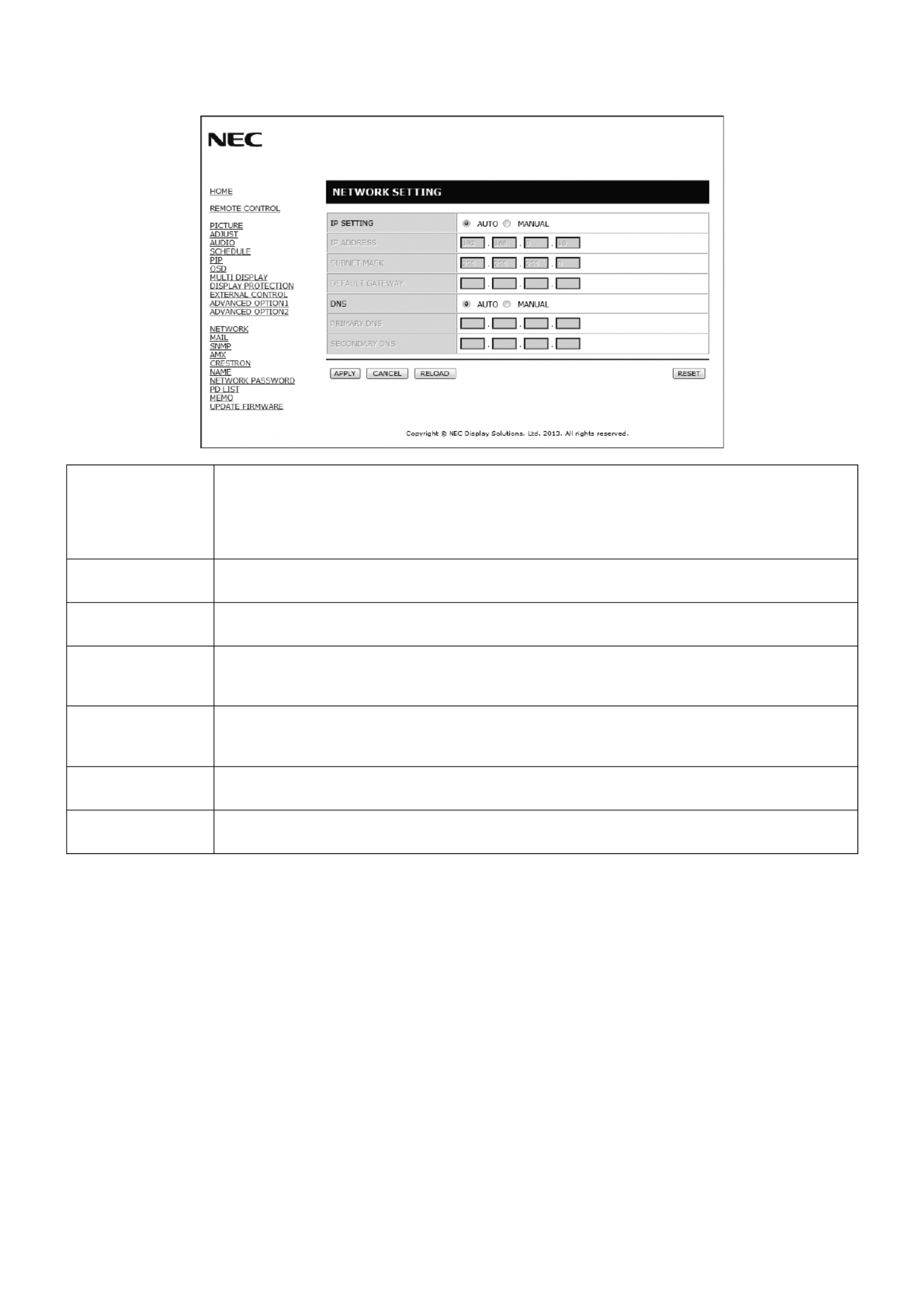
English-36
Network Setting
Click “NETWORK” on the left side of HOME.
IP SETTING Set for IP ADDRESS setting.
AUTO: Automatically assign an IP address.
MANUAL: Set your IP address of the network connected to the monitor.
NOTE: Consult your network administrator for the IP address when [AUTO] is selected for
[IP SETTING].
IP ADDRESS Set your IP address of the network connected to the monitor when [MANUAL] is selected for
[IP SETTING].
SUBNET MASK Set your subnet mask number of the network connected to the monitor when [MANUAL] is selected
for [IP SETTING].
DEFAULT GATEWAY Set your default gateway of the network connected to the monitor when [MANUAL] is selected for
[IP SETTING].
NOTE: Set as [0.0.0.0] to delete the setting.
DNS Set for IP ADDRESS setting of DNS server.
AUTO: Automatically assign an IP address of DNS server connected to the monitor.
MANUAL: Set your IP address of DNS server connected to the monitor.
PRIMARY DNS Set your primary DNS settings of the network connected to the monitor.
NOTE: Set as [0.0.0.0] to delete the setting.
SECONDARY DNS Set your secondary DNS settings of the network connected to the monitor.
NOTE: Set as [0.0.0.0] to delete the setting.
NOTE: The following settings will reset back to the factory setting when “IP ADDRESS RESET” is selected by an EXTERNAL
CONTROL of OSD:
[IP SETTING]: AUTO, [IP ADDRESS]: 192.168.0.10, [SUBNET MASK]: 255.255.255.0, [DNS]: AUTO [DEFAULT
GATEWAY], [PRIMARY DNS] and [SECONDARY DNS] are blank.

English-37
English
Mail Setting
Click “MAIL” on the left side of HOME.
This option notifi es your computer of an error message via e-mail when using wired LAN. An error message notifi cation will be
sent when an error occurs in the monitor.
ALERT MAIL Checking [ENABLE] will turn on the Alert Mail feature.
Checking [DISABLE] will turn off the Alert Mail feature.
STATUS MESSAGE Checking [ENABLE] will turn on the STATUS MESSAGE feature.
Checking [DISABLE] will turn off the STATUS MESSAGE feature.
HOST NAME Type in the hostname of the network connected to the monitor.
Up to 15 alphanumeric characters can be used.
DOMAIN NAME Type in the domain name of the network connected to the monitor.
Up to 60 alphanumeric characters can be used.
SENDER’S ADDRESS Type in the senders address. Up to 60 alphanumeric and symbols characters can be used.
SMTP SERVER Type in the SMTP server name to be connected to the monitor.
Up to 60 alphanumeric characters can be used.
RECIPIENT’S
ADDRESS 1 TO 3
Type in your recipient’s address. Up to 60 alphanumeric and symbols characters can be used.
AUTHENTICATION
METHOD
This selects the authentication method of the e-mail transmission.
POP3 SERVER This specifi es the address of the POP3 server that is used in the authentication of the e-mail.
USER NAME This sets the user name for logging into the authentication server when authentication is required
for the e-mail transmission. Up to 60 alphanumeric characters can be used.
TEST MAIL Click this button to send a test mail to check if your settings are correct.
NOTE: • If you execute a test, you may not receive an Alert mail.
Should this happen, check if the network settings are correct.
• If you entered an incorrect address in a test, you may not receive an Alert mail.
Should this happen, check if the Recipient’s Address is correct.
TIP: The Alert Mail settings will not be affected even when [RESET] is done from the menu.
For Control command diagram, please see fi le “External_Control.pdf” on the CD-ROM.

English-38
Alert error message list
Error number
* ErrorCode Alert mail Message Explanation Measure
70h ~ 7Fh The monitor’s power supply is not
functioning normally.
Standby power Abnormal Please contact your supplier.
80h ~ Fh The cooling fan has stopped. Cooling fan Abnormal Please contact your supplier.
90h ~ 9Fh The monitor’s back light unit is not
functioning normally.
Backlight abnormal Please contact your supplier.
A0h ~ AFh The monitor is overheated. Temperature Abnormal Please contact your supplier.
A2h
SENSOR reached at the temperature
that the user had specifi ed.
*condition: DISPLAY PROTECTION-FAN
CONTROL-COOLING FAN = AUTO
Reconfi rm the setting condition from
OSD (DISPLAY PROTECTION-FAN
CONTROL) or please contact your
supplier.
B0h ~ BFh The monitor doesn’t have the input
signal.
No signal Please check “No picture” in
“Troubleshooting”.
D0h The remaining capacity of the error log
decreased.
Proof of Play log memory size is 1 more
hour.
Please get a log by using PD external
command. See page 43.
E0h ~ EFh The system error occurred in the
monitor.
System error. Please contact your supplier.
Sample: The following examples are content of Alert Mail that informs the temperature anomaly of monitor.
Sample: The following examples are content of test mail by browser.
Produktspecifikationer
| Varumärke: | Nec |
| Kategori: | Övervaka |
| Modell: | MultiSync X464UN-TMX9P |
Behöver du hjälp?
Om du behöver hjälp med Nec MultiSync X464UN-TMX9P ställ en fråga nedan och andra användare kommer att svara dig
Övervaka Nec Manualer

9 April 2025
11 Februari 2025
11 Februari 2025
11 Februari 2025
7 Januari 2025
1 Januari 2025
1 Januari 2025
1 Januari 2025
14 Oktober 2024
11 Oktober 2024
Övervaka Manualer
- Övervaka Sony
- Övervaka Samsung
- Övervaka Xiaomi
- Övervaka LG
- Övervaka Bosch
- Övervaka Huawei
- Övervaka HP
- Övervaka Philips
- Övervaka Panasonic
- Övervaka Daewoo
- Övervaka Epson
- Övervaka Garmin
- Övervaka Honeywell
- Övervaka JVC
- Övervaka JBL
- Övervaka Medion
- Övervaka Olympus
- Övervaka Pioneer
- Övervaka Toshiba
- Övervaka Yamaha
- Övervaka Yealink
- Övervaka Canon
- Övervaka Abus
- Övervaka Ag Neovo
- Övervaka Acer
- Övervaka AOC
- Övervaka Apc
- Övervaka Alienware
- Övervaka Alpine
- Övervaka Alesis
- Övervaka Apple
- Övervaka Acti
- Övervaka Prestigio
- Övervaka Hikvision
- Övervaka BenQ
- Övervaka Sharp
- Övervaka Silvercrest
- Övervaka Hitachi
- Övervaka Thomson
- Övervaka Pyle
- Övervaka Emachines
- Övervaka Asus
- Övervaka Caliber
- Övervaka Hisense
- Övervaka Hyundai
- Övervaka Renkforce
- Övervaka Westinghouse
- Övervaka LC-Power
- Övervaka 3M
- Övervaka Blaupunkt
- Övervaka Maxdata
- Övervaka Lenovo
- Övervaka Thermaltake
- Övervaka EMOS
- Övervaka Salora
- Övervaka Denver
- Övervaka Omron
- Övervaka Tripp Lite
- Övervaka Optoma
- Övervaka DataVideo
- Övervaka Citizen
- Övervaka Schneider
- Övervaka Sanyo
- Övervaka Vitek
- Övervaka Sunstech
- Övervaka TCL
- Övervaka Gigabyte
- Övervaka Mitsubishi
- Övervaka Velleman
- Övervaka Sunny
- Övervaka BlueBuilt
- Övervaka Marquant
- Övervaka Da-Lite
- Övervaka Haier
- Övervaka Allen & Heath
- Övervaka Iiyama
- Övervaka ProXtend
- Övervaka Plantronics
- Övervaka Kubo
- Övervaka IFM
- Övervaka Mackie
- Övervaka Fujitsu
- Övervaka AJA
- Övervaka Adj
- Övervaka Element
- Övervaka Asrock
- Övervaka Razer
- Övervaka Neumann
- Övervaka RCF
- Övervaka Barco
- Övervaka Continental Edison
- Övervaka Dahua Technology
- Övervaka Insignia
- Övervaka Viessmann
- Övervaka GeoVision
- Övervaka Peerless-AV
- Övervaka Boss
- Övervaka LaCie
- Övervaka Ricoh
- Övervaka Behringer
- Övervaka Deltaco
- Övervaka PreSonus
- Övervaka Danfoss
- Övervaka Godox
- Övervaka Marshall
- Övervaka Dell
- Övervaka Focal
- Övervaka InFocus
- Övervaka Midas
- Övervaka Festo
- Övervaka IK Multimedia
- Övervaka Samson
- Övervaka Planar
- Övervaka Shure
- Övervaka Konig
- Övervaka Tesla
- Övervaka MSI
- Övervaka Orion
- Övervaka Viewsonic
- Övervaka Swissonic
- Övervaka Waeco
- Övervaka Ikan
- Övervaka IHealth
- Övervaka Chauvet
- Övervaka Peaq
- Övervaka Cooler Master
- Övervaka QSC
- Övervaka Hannspree
- Övervaka ESI
- Övervaka Avocor
- Övervaka Marshall Electronics
- Övervaka Simrad
- Övervaka Jensen
- Övervaka Jung
- Övervaka Vivitek
- Övervaka Newstar
- Övervaka Newline
- Övervaka Genelec
- Övervaka Interlogix
- Övervaka Eizo
- Övervaka Ring
- Övervaka HoverCam
- Övervaka Kindermann
- Övervaka EverFocus
- Övervaka Eurolite
- Övervaka RGBlink
- Övervaka POSline
- Övervaka Peerless
- Övervaka Dynaudio
- Övervaka Atomos
- Övervaka M-Audio
- Övervaka Smart
- Övervaka Mad Catz
- Övervaka NZXT
- Övervaka Krom
- Övervaka Vorago
- Övervaka Monoprice
- Övervaka Promethean
- Övervaka Odys
- Övervaka Yorkville
- Övervaka Fostex
- Övervaka Prowise
- Övervaka HyperX
- Övervaka Stairville
- Övervaka Crestron
- Övervaka Soundstream
- Övervaka Xoro
- Övervaka HKC
- Övervaka I3-Technologies
- Övervaka CTOUCH
- Övervaka Ozone
- Övervaka Ibm
- Övervaka Maxell
- Övervaka Packard Bell
- Övervaka Provision ISR
- Övervaka SPL
- Övervaka Monacor
- Övervaka BOOX
- Övervaka Aputure
- Övervaka Brandson
- Övervaka ARRI
- Övervaka Drawmer
- Övervaka Blue Sky
- Övervaka Zalman
- Övervaka Iadea
- Övervaka Advantech
- Övervaka Hercules
- Övervaka Sonifex
- Övervaka Kali Audio
- Övervaka Avantone Pro
- Övervaka Ganz
- Övervaka Extron
- Övervaka Legamaster
- Övervaka ELO
- Övervaka Belinea
- Övervaka AVer
- Övervaka Adam
- Övervaka Triton
- Övervaka ITek
- Övervaka Vimar
- Övervaka Kogan
- Övervaka Tannoy
- Övervaka Speco Technologies
- Övervaka Posiflex
- Övervaka Akuvox
- Övervaka Jay-tech
- Övervaka Antelope Audio
- Övervaka MicroTouch
- Övervaka X-Rite
- Övervaka EKO
- Övervaka ONYX
- Övervaka IBoardTouch
- Övervaka Mirai
- Övervaka PeakTech
- Övervaka Elite Screens
- Övervaka Hollyland
- Övervaka Mitsai
- Övervaka Kramer
- Övervaka V7
- Övervaka Skytronic
- Övervaka Palmer
- Övervaka TV One
- Övervaka Christie
- Övervaka Hanwha
- Övervaka Phoenix Contact
- Övervaka COMMBOX
- Övervaka Yiynova
- Övervaka Pelco
- Övervaka Lilliput
- Övervaka LightZone
- Övervaka KRK
- Övervaka Joy-it
- Övervaka AOpen
- Övervaka Ernitec
- Övervaka Planet Audio
- Övervaka EC Line
- Övervaka Datacolor
- Övervaka Fluid
- Övervaka Postium
- Övervaka Atlona
- Övervaka HELGI
- Övervaka Desview
- Övervaka Syscom
- Övervaka Allsee
- Övervaka Alogic
- Övervaka Night Owl
- Övervaka ProDVX
- Övervaka Varad
- Övervaka PureTools
- Övervaka DoubleSight
- Övervaka CTL
- Övervaka Game Factor
- Övervaka Nixeus
- Övervaka Chimei
- Övervaka Blue Sea
- Övervaka AMCV
- Övervaka Faytech
- Övervaka Hamlet
- Övervaka Wyse - Dell
- Övervaka Approx
- Övervaka SWIT
- Övervaka Bauhn
- Övervaka TVLogic
- Övervaka Feelworld
- Övervaka GeChic
- Övervaka Oecolux
- Övervaka ADS-TEC
- Övervaka Satco
- Övervaka SEIKI
- Övervaka Casalux
- Övervaka AMX
- Övervaka Positivo
- Övervaka Jupiter
- Övervaka Transvideo
- Övervaka Innocn
- Övervaka KeepOut
- Övervaka Shimbol
- Övervaka Raysgem
- Övervaka Motrona
- Övervaka Ikegami
- Övervaka AORUS
- Övervaka Elvid
- Övervaka Wohler
- Övervaka Portkeys
- Övervaka Mimo Monitors
- Övervaka Neat
- Övervaka Gamber-Johnson
- Övervaka Enttec
- Övervaka American Dynamics
- Övervaka AIS
- Övervaka Eve Audio
- Övervaka Wortmann AG
- Övervaka Viotek
- Övervaka Vidi-Touch
- Övervaka KTC
- Övervaka CoolerMaster
- Övervaka Mobile Pixels
- Övervaka Atlantis Land
- Övervaka HEDD
- Övervaka Colormetrics
- Övervaka SMART Technologies
- Övervaka Monkey Banana
- Övervaka SmallHD
- Övervaka IStarUSA
- Övervaka Qian
- Övervaka UPERFECT
- Övervaka Freedom Scientific
- Övervaka OSEE
- Övervaka GVision
- Övervaka Voxicon
- Övervaka CSL
- Övervaka Mybeo
- Övervaka Bearware
- Övervaka IOIO
- Övervaka DTEN
- Övervaka Cocopar
- Övervaka Titan Army
- Övervaka Xenarc
- Övervaka Delvcam
- Övervaka Wimaxit
- Övervaka BookIT
- Övervaka SideTrak
- Övervaka TRIUMPH BOARD
- Övervaka Japannext
Nyaste Övervaka Manualer
9 April 2025
8 April 2025
8 April 2025
7 April 2025

5 April 2025

5 April 2025
4 April 2025
4 April 2025
2 April 2025
2 April 2025