StarTech.com SV831DUTP Bruksanvisning
StarTech.com
Växla
SV831DUTP
Läs nedan 📖 manual på svenska för StarTech.com SV831DUTP (54 sidor) i kategorin Växla. Denna guide var användbar för 13 personer och betygsatt med 4.5 stjärnor i genomsnitt av 2 användare
Sida 1/54

*8 Port Model Shown

FCC Compliance Statement
This equipment has been tested and found to comply with the limits for a Class B digital
device, pursuant to part 15 of the FCC Rules. These limits are designed to provide reasonable
protection against harmful interference in a residential installation. This equipment generates,
uses and can radiate radio frequency energy and, if not installed and used in accordance with
the instructions, may cause harmful interference to radio communications. However, there is
no guarantee that interference will not occur in a particular installation. If this equipment does
cause harmful interference to radio or television reception, which can be determined by turn-
ing the equipment off and on, the user is encouraged to try to correct the interference by one
or more of the following measures:
Reorient or relocate the receiving antenna.•
Increase the separation between the equipment and receiver.•
Connect the equipment into an outlet on a circuit different from that to which the receiver •
is connected.
Consult the dealer or an experienced radio/TV technician for help.•
Use of Trademarks, Registered Trademarks, and other Protected Names and Symbols
This manual may make reference to trademarks, registered trademarks, and other protected
names and/or symbols of third-party companies not related in any way to StarTech.com.
Where they occur these references are for illustrative purposes only and do not represent an
endorsement of a product or service by StarTech.com, or an endorsement of the product(s)
to which this manual applies by the third-party company in question. Regardless of any direct
acknowledgement elsewhere in the body of this document, StarTech.com hereby acknowl-
edges that all trademarks, registered trademarks, service marks, and other protected names
and/or symbols contained in this manual and related documents are the property of their
respective holders.

i
Safety Precautions ....................................................................... iii
Introduction .................................................................................... 1
Features ......................................................................................1
Package contents ........................................................................1
Hardware Guide ............................................................................. 2
Installation ...................................................................................... 6
Stacking Switches and Rack Mounting .......................................6
Single Station Installation ............................................................8
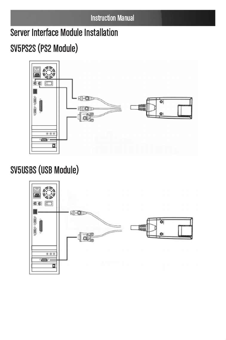
Server Interface Module Installation ............................................10
SV5PS2S (PS2 Module)..............................................................10
SV5USBS (USB Module) ............................................................10
Daisy Chaining ............................................................................11
Daisy Chain Installation Diagram ................................................12
Basic Operation ............................................................................. 13
Port Selection ..............................................................................13
Hot Plugging ................................................................................13
Powering Off and Restarting .......................................................14
Port ID Numbering .......................................................................15
OSD Operation ............................................................................... 15
Overview ......................................................................................15
OSD Navigation ...........................................................................17
OSD Main Screen Headings .......................................................17
OSD Functions ............................................................................17
Hotkey Operation ........................................................................... 27

ii
Hotkey Port Control .....................................................................27
Auto Scanning .............................................................................28
Skip Mode....................................................................................29
Hotkey Beeper Control .................................................................. 30
Hotkey Summary Table ................................................................30
Keyboard Emulation ...................................................................... 32
Mac Keyboard..............................................................................32
Sun Keyboard ..............................................................................33
Firmware Upgrades ....................................................................... 34
Introduction ..................................................................................34
Performing the Upgrade ..............................................................35
Server Interface Module Upgrade ................................................ 37
Performing the Upgrade ..............................................................38
Firmware Upgrade Recovery .......................................................39
Connection Tables ......................................................................... 40
Administrator Login Failure ......................................................... 42
OSD Factory Default Settings ...................................................... 43
Specifications ................................................................................ 44
Technical Support ........................................................................46
Warranty Information ...................................................................46

iii
The following precautions should be employed to ensure safe, reliable
operation of this device:
Read the enclosed instructions, and save them for future reference
Do not place the device on an unstable surface. If the device falls, •
serious damage will result
Follow all warnings and instructions marked on the device (if •
applicable)
Do not use the device near water•
Do not place the device near or over any device that produces heat (i.e. •
radiators, heat registers etc.)
To ensure adequate ventilation and reliable operation, never block the •
vent openings
Do not place the device on a soft surface (i.e. bed, carpet, etc.) as this •
will block ventilation openings. Similarly, never place the device in a
built-in enclosure unless adequate ventilation is provided
Never spill liquid of any kind on the device•
Unplug the device from the wall, prior to cleaning. Do not use liquid or •
aerosol cleaners, instead use a damp cloth
The device should be operated from the type of power source indicated •
on the marking label. If you are unsure of the type of power available,
please contact your local power company
The device is equipped with a 3-wire grounding type plug. This is a •
safety feature that should be left intact at all times. If you are unable to
insert the plug into the outlet, contact your electrician to replace the
available (outdated) outlet. Do not attempt to defeat the purpose of or
bypass the grounding-type plug; always follow local wiring codes
Position system cables and power cables carefully. Do not allow •
anything to rest on the power cord or cables. Route the power cord
and cables so that they cannot be stepped or tripped on
If an extension cord is used with this device, make sure that the •

iv
combined ampere rating of all products used on the cord does not
exceed the extension cord ampere rating. Make sure that the total of
all devices connected to the wall outlet does not exceed 15 amperes
To help protect your system from sudden, transient increases and •
decreases in electrical power, use a surge suppressor, line conditioner
or Uninterruptible Power Supply (UPS)
Follow all warnings and instructions marked on the device (if •
applicable)
When connecting or disconnecting power to hot pluggable power •
supplies, observe the following guidelines:
Install the power supply before connecting the power cable to the
power supply
Unplug the power cable before removing the power supply
If the system has multiple sources of power, disconnect power by
unplugging all power cables from the power supplies
Never push objects of any kind into or through cabinet slots. They
may touch dangerous voltage points or short out components,
risking fire or electrical shock.
Do not attempt to service the device yourself. Please refer all servicing •
to qualified service personnel
Unplug the device from the wall outlet, and consult with a qualified •
service technician, if any of the following conditions occur:
The power cord is frayed or damaged
Liquid has been spilled into the device, or the device has been
exposed to rain or water
The device has been dropped, or the casing has been damaged
The device exhibits a distinct decline in performance, indicating a

v
need for service
The device does not operate normally, when following the operating
instructions
Only adjust controls that are described in the following operating •
instructions. Improper adjustment of other controls may result in
damage that could lead to extensive repair

1
Thank you for purchasing a StarTech.com CAT 5 KVM switch. Allowing
control of up to 8 (SV831DUTP) or 16 (SV1631DUTP) computers over a
CAT 5 cable connection (between the switch and the slave computers),
this device provides a cost-effective solution that’s simple to install, and
equally easy to configure and control through pushbutton operation, hot-
key commands or the convenient On-Screen Display.
Auto-scan function automates sequential computer selection•
Cascade configuration expands system capability up to 256 computers •
(SV831DUTP) or 512 computers (SV1631DUTP)
Allows for easy computer selection using front panel pushbuttons, •
hotkeys and intuitive On-Screen Display
Hot Pluggable - add or remove computers without having to power •
down the switch
1 x StarView CAT5 KVM Switch
1 x User Manual
1 x Power Adapter
1 x Mounting Bracket Kit
1 x Firmware Upgrade Cable
Please note that when accessing the Switch, you will be asked to supply
a Username and Password.
In the Username field, press the key on the connected keyboard.Enter
In the Password field, press the key. You will then be logged into Enter
the On Screen Display.
2
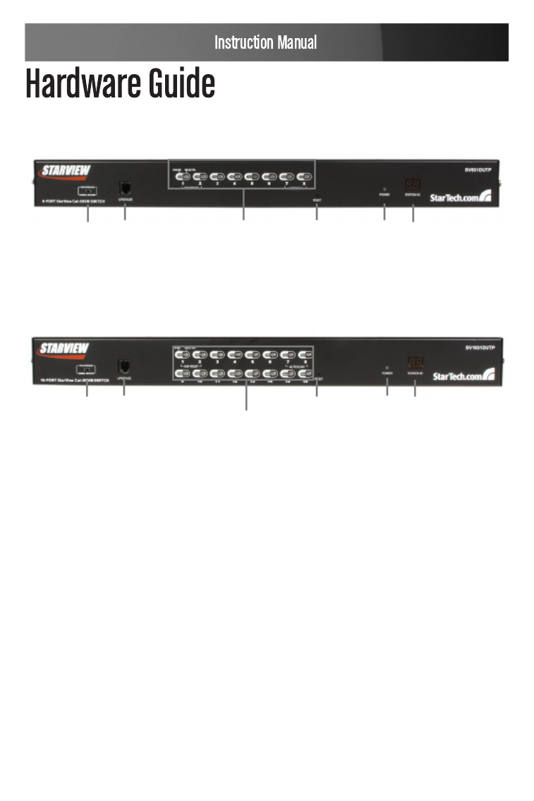
Front Panel View SV831DUTP
Front Panel View SV1631DUTP
1&2 734 5 6
1&2
3 764 5
Please refer to the tables on pages 3 and 4 for descriptions
of the above illustrations.

3
Component Functions (Front Panel)
Component Description
1
Port
Selection
Switches
a. Press a switch to give the KVM focus to the
computer attached to its corresponding port.
b. Simultaneously pressing buttons 1 and 2 for 3
seconds performs a Keyboard and Mouse Reset.
c. Simultaneously pressing buttons 7 and 8 starts Auto
Scan Mode.
2 Port LEDs
The Port LEDs are built into the Port Selection Switches.
The upper ones are the On Line LEDs; the lower ones
are the Selected Port LEDs:
a. An On Line LED lights GREEN to indicate that the
computer attached to its corresponding port is up and
running. A flashing LED indicates that the Port is being
used for cascading to another switch.
b. A Selected LED lights ORANGE to indicate that the
computer attached to its corresponding port is the one
that has the KVM focus.
The LED is steady under normal conditions, but flashes
when its port is accessed under Auto Scan Mode.
3Reset
Switch
Pressing this switch in performs a system reset. Note:
The switch is recessed and must be pushed with a thin
object - such as the end of a paper clip, or a ballpoint
pen.
4
Firmware
Upgrade
Recovery
Switch
During normal operation and while performing a firmware
upgrade, this switch should be in the NORMAL position.
If a firmware upgrade operation does not complete
successfully, this switch is used to perform a firmware
upgrade recovery.

4
Component Description
5
Firmware
Upgrade
Port
The Firmware Upgrade Cable that transfers the firmware
upgrade data from the administrator’s computer to the
SV831DUTP / SV1631DUTP, plugs into this RJ-11
connector.
6 Power LED Lights to indicate that the SV831DUTP / SV1631DUTP is
powered up and ready to operate.
7Station ID
LED
The SV831DUTP / SV1631DUTP’s Station ID is
displayed here. If this is a Single Station installation
(see page 12), or the First Station on a Daisy
Chained installation (see page 15), the SV831DUTP /
SV1631DUTP has a Station ID of 01.
On a Daisy Chained installation, the SV831DUTP /
SV1631DUTP autosenses its position and displays the
Station ID that corresponds to its place in the chain. (see
Port ID Numbering, page 15, for details).
Rear Panel View (SV831DUTP)
Rear Panel View (SV1631DUTP)
Please refer to the table on page 5 for descriptions of the
above illustrations.

5
Component Functions (Rear Panel)
Component Description
1Power Socket
2 Power Switch
3
Daisy Chain Ports
When Daisy Chaining Units, the daisy chain
cables plug in here. The port on the left is
the Chain In port; the port on the right is the
Chain Out port.
4
Local Console Port
Section
If this is a Single Station installation, or if
this is the First Station of a daisy chained
installation, the keyboard, monitor, and
mouse that make up the Local Console plug
in here.
5
KVM Port Section
The Cat 5 cables that link to the KVM Adapter
Cables (which link to the computers) plug in
here.

6
Please ensure you have reviewed the safety precautions listed
on page iii - v, before proceeding with installation.
Please make sure that power to all of the devices that will
be connected to the switch has been shut off; similarly, you
must unplug the power cords of any computers that have the
Keyboard Power On function.
SV831DUTP and SV1631DUTP can be stacked on the desktop or rack
mounted at the front or rear of the rack. The following sections take you
through the procedures for each method.
Stacking
SV831DUTP and SV1631DUTP can be placed on any appropriate level
surface that can safely support its weight plus the weight of its attached
cables. To place SV831DUTP / SV1631DUTP, or to stack units if you are
daisy chaining them, remove the backing material from the bottom of the
rubber feet that came with this package, and stick them onto the switch’s
bottom panel at the corners, as shown in the diagram, below:

7
Please Note: To ensure adequate ventilation, allow at least 5.1cm (2”) on
each side, and 12.7cm (5”) at the back for power cord and cable clear-
ance.
Rack Mounting
SV831DUTP and SV1631DUTP can be mounted in a 19” (1U) rack. The
mounting brackets can screw into either the front or the back of the unit
so that it can attach to the front or the back of the rack. To rack mount the
unit:
Remove the screws at the front or the rear, as shown in the diagram 1.
below:
Screw the mounting brackets into the sides of the unit at the front or 2.
the rear, as shown in the diagram on the following page:
M3 x 6
Philips
head hex
M3 x 6
Philips
head hex

8
M3 x 8
Philips
head hex
M3 x 8
Philips
head hex
3. Slide the unit into the front or rear of the rack and secure it to the rack.
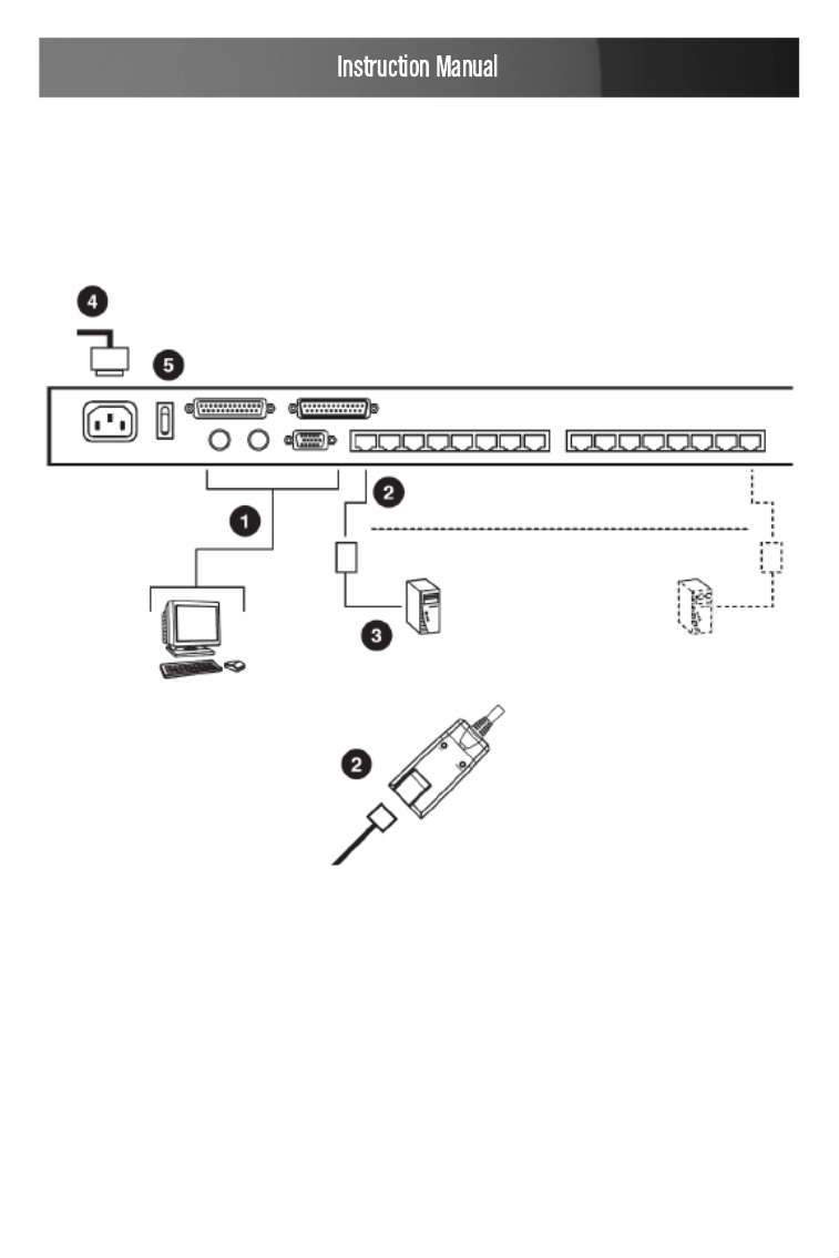
In a Single Stage installation, there are no additional KVM switches cas-
caded down from SV831DUTP / SV1631DUTP. To set up a single stage
installation, refer to the installation diagrams on the following page (the
numbers in the diagram correspond with the numbers of the instruction
steps), and do the following:
Plug your Local Console’s keyboard, monitor, and mouse into the 1.
unit’s Console Ports. Each port is color coded and marked with an
appropriate icon to identify itself.
Use Cat. 5 cable to connect any available KVM port to a KVM Adapter 2.
Cable that is appropriate for the computer you are installing.
Please Note: SV831DUTP / SV1631DUTP does not support distances
between itself and the KVM Adapter Cable that exceed 40 m (130’).
Connect the KVM Adapter Cable to the computer. Plug the connectors 3.
on the KVM Adapter Cable into the appropriate ports of the computer
you are installing.
9
Plug the female end of the power cord into the SV831DUTP/ 4.
SV1631DUTP Power Socket; plug the male end into an AC power
source.
Turn on the power to SV831DUTP / SV1631DUTP. After the switch is 5.
powered up, you can turn on the computers.
10

11
To control more computers than would be supported by SV831DUTP /
SV1631DUTP in a signal stage installation (eight and sixteen respec-
tively), up to 31 additional switches can be cascaded from the KVM ports
of the SV831DUTP / SV1631DUTP. As many as 512 computers can be
controlled from a single console in a complete installation.
Tables showing the relation between the number of computers and the
number of SV831DUTP or SV1631DUTP units needed to control them
are provided on page 40. To set up a daisy chained installation, do the
following:
Use a Straight Through DB25 M/F cable ( see StarTech.com part num- 1.
bers SC6MF or SC10MF) to connect the Chain Out port of the parent
SV831DUTP / SV1631DUTP unit to the Chain In port of the child
SV831DUTP / SV1631DUTP unit (First Station Out to Second
Station In, Second Station Out to Third Station In, etc.).
Please Note: You cannot use the Chain In port of the First Station, since
it is the highest level parent.
Use Cat. 5 cable to connect any available KVM port to the appropriate 1.
KVM Adapter Cable.
Please Note: The SV831DUTP / SV1631DUTP does not support
distances between itself and the KVM Adapter Cable that exceed 40 m
(130’)
Connect the KVM Adapter Cable to the computer.1.
Use the power cord supplied with this package to connect the 2.
SV831DUTP / SV1631DUTP to an AC power source.
Repeat steps 1–4 for any other switches you wish to add to the chain.3.
Power up the installation according to the following procedure: 4.
a) Plug in the power adapter for the First Station. Wait for the unit to
determine its Station ID and display it on the Station ID LED. (The
Station ID for the First Stage unit is 01, the ID for the Second Stage
unit is 02, the ID for the Third Stage unit is 03, etc.)
b) Power on each station on the installation in turn (Second Station,
then Third Station, etc.). In each case, wait for the Station ID to be

12
displayed before powering on the next station.
c) After all stations are up, power on the computers.

13
SV831DUTP / SV1631DUTP installations provide three ways to obtain
instant access to any computer in your installation: Manual, OSD, and
Hotkey.
Manual
For manual port selection, simply press the Port Switch that corresponds
with the device you want to access. For cascaded switches, first press
the Port Switch on the parent unit that the cascaded switch is connected
to, then press the Port Switch on the cascaded switch that corresponds to
the device you wish to access.
OSD
OSD (On Screen Display), provides menu-driven computer switching.
Hotkey
Hotkeys allow you to conveniently direct KVM focus to a particular
computer from the keyboard, instead of having to manually select the
computer by pressing Port Selection switches.
SV831DUTP / SV1631DUTP supports hot plugging, allowing components
to be removed and added back into the installation by unplugging and
re-plugging their cables from their ports without having to shut the unit
down. In order for hot plugging to work properly, however, the procedures
described on the following page must be followed:
Hot Plugging Stations
You can switch station positions by simply unplugging from the old parent

14
and plugging into a new one. Following this, in order for the OSD menus
to accordingly reflect the change, you must reset the OSD. See RESET
STATION IDS, page 24, for details.
Hot Plugging KVM Ports
After switching KVM ports, in order for the OSD menus to accurately
reflect the change, you must manually reconfigure the OSD information
for the new Port information. See F3 SET, page 19, and the Port Setting
selections under the F4 ADM function, page 21, for details.
Please Note: If the computer’s Operating System doesn’t support hot
plugging, this function may not work properly.
Hot Plugging Console Ports
Keyboard, monitor, and mouse can all be hot plugged. When hot plugging
the mouse:
You may unplug the mouse and plug it back in again (to reset the •
mouse, for example), as long as you use the same mouse.
If you plug in a different mouse, all the stations and all the computers •
on the installation must be shut down for 10 seconds, then restarted
following the Power Up Sequence described on page )9.
Please Note: If, after hot plugging (or at any other time), there is no
response to keyboard and/or mouse input, perform a Keyboard and
Mouse Reset by pressing in the Reset switch (see #3, page 3).
If it becomes necessary to power off the switch, or if the switch loses
power and needs to be restarted, before re-starting you must follow these
procedures:
Shut down all the computers that are attached to the switch. 1. You Note:
must unplug the power cords of any computers that have the Keyboard
Power On function.
Wait 10 seconds then power the switch back on. If you have shut down 2.

15
more than one station, power up the highest station first and work your
way down to the lowest station. Wait for each station to display its
Station ID on the front panel LED before powering on the subsequent
station.
After the station(s) is (are) up, power the computers back on. 3.
Each computer on the installation is assigned a unique Port ID. The Port
ID is a one or two segment number determined by the Stage Level and
KVM Port number of the KVM switch to which the computer is connected.
The first segment represents the KVM Port number of the First Stage
unit, the second segment represents the KVM Port number of the Second
Stage unit.
A computer attached to a First Stage unit has a one segment Port ID
(from 1-16) corresponding with the KVM Port number to which it is con-
nected.
A computer attached to a Second Stage unit has a two segment Port ID:
The second segment (from 1-8), represents the KVM Port number on •
the Second Stage unit to which the computer is connected. The first
segment (from 1-16) represents the KVM Port number on the First
Stage unit to which the Second Stage unit is linked.
As an example, a Port ID of 12 - 3 refers to a computer connected to
KVM Port 3 of a Second Stage unit that links back to KVM Port 12 of
the First Stage unit.
The On Screen Display (OSD) is a menu-driven method to handle com-
puter control and switching operations. All procedures start from the OSD
Main Screen. To pop up the Main Screen, tap [Scroll Lock] twice.

16
Please Note: You can optionally change the Hotkey to the Ctrl key, in
which case you would tap twice. With this method, the Ctrl keys [Ctrl]
used must be on the same side (both left, or both right).
The OSD incorporates a two level (Administrator / User) password sys-
tem. Before the OSD Main Screen comes up, a dialog box appears that
asks you to provide your password. If the password function has been set,
you must provide the password in order to access the OSD Main Screen.
If this is the first time that the OSD is being run, or if the password func-
tion has not been set, simply press [Enter]. The OSD Main Screen comes
up in Administrator Mode. In this mode, you have Administrator privileges,
with access to all Administrator and User functions, and can set up opera-
tions (including password authorization for the future), as you would like.
When you invoke the OSD, a screen similar to the one below appears:
Please Note:
The diagram depicts the Administrator’s Main Screen. The User Main 1.
Screen does not show the F4 function as it is reserved for the
Administrator and cannot be accessed by ordinary Users.
The OSD always starts in List view, with the highlight bar at the same 2.
position it was in the last time it was closed.
Only the ports that have been set accessible by the Administrator for 3.
the currently logged in User are visible.

17
To dismiss the menu, and deactivate the OSD, press • [Esc]
To Logout, press • [F8]
To move up or down through the list one line at a time, use the • Up and
Arrow Keys. If there are more list entries than there is room for Down
on the Main Screen, the screen will scroll.
To bring the KVM focus to a port, move the Highlight Bar to it then •
press [Enter]
After executing any action, you automatically go back to the menu one •
level above
OSD functions are used to configure and control the OSD. For example,
rapidly switching to any port, scanning only selected ports, limiting the
list of ports you wish to view, designating a port as a Quick View Port,
managing port names or making OSD setting adjustments.
Heading Explanation
SN-PN This column lists the Port ID numbers (Station Number - Port
Number) for all Computer Ports on the installation. The simplest
method to access a particular computer is to scroll to the desired
selection using the up and down arrow keys, then press Enter
QV If a port has selected for Quick View scanning, an arrowhead will
be displayed in this column
The computers that are powered on and are On Line will be
indicated in this column with a Sun symbol
NAME If a port has been given a name its name appears in this column.

18
To access an OSD function:
Press a Function Key on the keyboard.1.
In the Submenus that appear, make your choice by scrolling the 2.
Highlight Bar to it, then pressing .[Enter]
Press 3. to return to the previous menu level. [Esc]
F1 GOTO
Pressing [F1] activates the GOTO function. GOTO allows you to switch
directly to a port either by keying in the port’s Name, or its Port ID.
To use the Name method - key in 1, key in the port’s Name; then press •
[Enter]
To use the Port ID method - key in 2, key in the Port ID; then press •
[Enter]
F2 LIST
This function allows you to broaden or narrow the scope of which ports
the OSD displays (lists) on the Main Screen. Many of the OSD functions
only operate on the computers currently selected for listing on the Main
Screen with this function. The submenu choices and their meanings are
given in the table below:
Choice Meaning
ALL Lists all of the ports on the
installation
POWERED ON Lists only the ports that are
connected to powered computers
QVIEW Lists only the ports that have been
selected as Quick View Ports
QVIEW +
POWERED ON
Lists only the ports that have been
selected as Quick View Ports and
that have their attached computers
powered on.

19
Move the Highlight Bar to the choice you want, then press . An [Enter]
icon appears before the choice indicating that it is currently selected.
F3 SET
This function allows the Administrator and each User to personalize/con-
figure their own working environment. A separate profile for each is stored
by the OSD and is activated according to the Username that is provided
during Login. To change a setting:
Move the highlight bar to it, then press 1. .[Enter]
After you select an item, a submenu with further choices will appear. To 2.
make a selection, move the Highlight Bar to it, then press . An [Enter]
icon will appear next to the selection.
Setting Function
OSD HOTKEY Selects which Hotkey activates the OSD function:
[Scroll Lock] [Scroll Lock] [Ctrl] [Ctrl] (default) or .
PORT ID
DISPLAY
POSITION
Allows you to position where the Port ID appears on the
monitor. The default is the upper left corner, but you can
have it appear anywhere on the screen.
Use the Arrow Keys plus , , , [Pg Up] [Pg Dn] [Home]
[End], and 5 (on the numeric keypad with Num Lock
off), to position the Port ID display, then press to [Enter]
lock the position and return to the Set submenu.
PORT ID
DISPLAY
DURATION
Determines how long a Port ID displays on the monitor
after a port change has taken place. The choices are:
User Defined - Allows you to select the amount of time
(from 1 - 255 sec.)
Always On - which displays the Port ID at all times
If you select , key in the number of User Defined
seconds, then press . The default is 3 Seconds. [Enter]
A setting of 0 (zero) disables this function.

20
Setting Function
QVIEW +
POWERED ON
Lists only the ports that have been selected as Quick
View Ports and are connected to powered computers
PORT ID
DISPLAY
MODE
Selects how the Port ID is displayed
Options include: The Port Number alone (PORT
NUMBER), the Port Name alone ( ), or PORT NAME
the Port Number plus the Port Name (PORT NUMBER
+ PORT NAME) (default)
SCAN
DURATION
Determines how long focus is given to each port as it
cycles through the selected ports in Auto Scan Mode.
Key in a value from 1 - 255 seconds, then press [Enter].
Default is 5 seconds; a setting of (zero) disables the 0
Scan function.
SCAN/SKIP
MODE
Selects which computers will be accessed under Skip
Mode and Auto Scan Mode
Choices are: - All the Ports which have been set as ALL
Accessible
POWERED ON - Only those Ports which are powered
and have been set as accessible and
are Powered On
QUICK VIEW - Only those Ports which have
been set Accessible and have
been selected as Quick View
Ports
QUICK VIEW + POWERED ON - Only Ports set
as Accessible and have been
selected as Quick View Ports
and are Powered On.
SCREEN
BLANKER
If there is no input from the console for the amount of
time set with this function, the screen is blanked. Key in
a value from 1 - 30 minutes, then press [Enter]
A setting of (zero) disables this function (default)0
HOTKEY
COMMAND
MODE
Enables or Disables the Hotkey Command function in
case a conflict with programs running on the computers
occurs. The default is ON.

21
F4 ADM
F4 is an Administrator only function, which allows the Administrator to
configure the overall operation of the OSD. To change a setting use the
Up and Down Arrow Keys to move the highlight bar, then press [Enter].
Following item selection, a submenu with further choices appears. Move
the Highlight Bar to the desired selection, then press . An icon ap-[Enter]
pears before the selected choice for easier identification.The settings are
explained in the following table:
Setting Function
SET USERNAME
AND PASSWORD
This function is used to set Usernames and
Passwords for the Administrator and Users:
1. One Administrator and four User passwords
can be set.
2. After you select the Administrator field or one
of the User fields, a screen that allows you
to key in your password appears. The
password may be up to 15 characters long,
and can consist of any combination of letters
and numbers (A - Z, 0 - 9).
3. For each individual, key in the Username and
Password, then press .[Enter]
4. To modify or delete a previous Username and/
or Password, use the backspace key to erase
individual letters or numbers.
SET LOGOUT
TIMEOUT
If there is no input from the console for the amount
of time set with this function, the Operator is
automatically logged out. A login is necessary
before the console can be used again.
This enables other Operators to gain access to the
computers when the original Operator is no longer
accessing them, but has forgotten to log out. To set
the timeout value, key in a number from 1 - 180
minutes, then press . If the number is [Enter] 0
(zero), this function is disabled (default).

22
Setting Function
EDIT PORT NAMES
To help remember which computer is attached to a
particular port, every port can be given a name. This
function allows the Administrator to create, modify,
or delete port names. To Edit a port name:
1. Use the Navigation Keys to move the highlight
bar to the port you want, then press ]. [Enter
2. Key in the new Port Name, or modify/delete
the old one. The maximum number of
characters allowed for the Port Name is 12.
Legal characters include:
All alpha characters: a - z; A - Z
All numeric characters: 0 - 9
+ - / . and Space
The entered information is NOT case sensitive,
rather the Port Name will be displayed in all capitals.
3. When you have finished editing, press [Enter]
to implement the change. To abort the
change, press [Esc]
RESTORE DEFAULT
VALUES
This function is used to undo all changes and return
the setup to the original factory default settings,
except for the Names settings that were assigned
to the Ports
CLEAR THE NAME
LIST
Similar to Restore Default Values with the exception
that this feature also clears the Names settings
along with undoing all changes and returning the
setup to the original factory default settings.
ACTIVATE BEEPER
Choices are:
(ON) or (OFF)Y N
When activated, the beeper sounds whenever a
Port is changed, the Auto Scan function is activated
or an invalid entry is made on an OSD menu

23
Setting Function
SET QUICK VIEW
PORTS
This function lets the Administrator select which
Ports to include as Quick View ports:
To select/deselect a port as a Quick View Port, •
use the Navigation Keys to move the highlight
bar to it, then press [Enter]
When a port has been selected as a Quick View •
Port, an arrowhead will be displayed in the QV
column of the LIST on the Main Screen to
indicate so. When a port is deselected, the
arrowhead disappears
If one of the Quick View options is chosen for •
the LIST view, only a Port that has been selected
here will display on the List
If one of the Quick View options is chosen for •
Auto Scanning, only a Port that has been
selected here will be Auto Scanned. The default
is for no ports to be selected.
SET ACCESSIBLE
PORTS
This function allows the Administrator to define User
access to the computers on the installation on a
Port-by-Port basis. For each User, select the target
Port, then press the to cycle through [Spacebar]
the choices:
F V Blank (Full access), (View Only), or (No access
rights granted, Port will not appear on the User’s
LIST on the Main Screen.)
Repeat until all access rights have been set, then
press [Enter].
The default is F for all users on all Ports.

24
Setting Function
RESET STATION
IDS
If you change the position of one of the Stations
in the daisy chain, the OSD settings will no longer
apply. This function directs the OSD to rescan
the station positions of the entire installation
and updates the OSD so that the OSD Station
information corresponds to the new physical layout.
Only the Station Numbers get updated. Except for
the Port Names, all Administrator settings (such as
Set Accessible Ports, Set Quick View Ports, etc.),
for all computers affected by the change, have to be
manually reset.
FIRMWARE
UPGRADE
In order to upgrade the firmware for SV831DUTP/
SV1631DUTP you must first invoke Firmware
Upgrade Mode with this setting
PORT SETTING This screen lets you set three functions for the port:
the length of the Cat 5 cable from the port to the
KVM Adapter, the Operating System used by the
computer connected to the port, and the Keyboard
Language for the computer connected to the port.
•Press[Spacebar] to cycle through the cable
length settings:
: Short – for up to 20 mS
: Medium – for be tween 20 and 40 mM
: Long – for between 40 and 60 mL
An S, M, or L appears next to the port in the L
column indicating the selection
•Press[Enter] to cycle through the Operating
System settings: PC, Mac, or Sun
•Press [Tab] to cycle through the Keyboard
Language settings:USA, GBR, FRA, JPN, KOR.
Please Note: For German or Chinese, select USA.

25
Setting Function
ADAPTER
UPGRADE
In order to upgrade the Adapter Cables’ firmware,
you must first invoke its Upgrade Mode with this
setting
F5 SKP
Pressing invokes Skip (SKP) Mode. This function enables you to [F5]
easily skip backward or forward - switching the console focus from the
currently active computer port to the previous or next available one.
The selection of computers to be available for Skip Mode switching is
made with the Scan/Skip Mode setting under the F3 SET function.
When you are in Skip Mode, press [ ] to switch to the previous com-←
puter in the list, press [ ] to switch to the next computer in the list, press →
[ ↑ ] to switch to the last computer on the previous station in the list, press
[ ] to switch to the first computer on the next station in the List.↓
Please Note: When you Skip, you only Skip to the previous or next avail-
able computer that is in the Scan/Skip Mode selection.
If a Port has been selected for Scan/Skip Mode, a left/right triangle •
symbol next to its Port ID Display will denote focus
While Skip Mode is in effect, the console will not function normally. You •
must exit Skip Mode in order to regain control of the console.
To exit Skip Mode, press • [Spacebar] [Esc] or
F7 SCAN
Pressing invokes Auto Scan Mode. This function allows you to [F7]
automatically switch among the available computers at regular intervals
so that you can monitor their activity without having to take the trouble of
switching manually.
The selection of computers to be included for Auto Scanning is made •
with the Scan/Skip Mode setting under the F3 SET function
The amount of time that each Port displays for is set with the Scan •
Duration setting under the F3 SET function. When you want to stop at
a particular location, press the to stop scanning and exit [Spacebar]

26
Auto Scan Mode.
If the scanning stops on an empty port, or one where the computer •
is attached but is powered Off, the monitor screen will be blank, and
the mouse and keyboard will have no effect. Simply wait - after the
Scan Duration time is up, the Scan function will move on to the next
port.
As each computer is accessed, an • S appears in front of the Port ID
display to indicate that it is being accessed under Auto Scan Mode.
While Auto Scan Mode is in effect, the console will not function •
normally. You must exit Auto Scan Mode in order to regain control of
the console.
While you are in Auto Scan Mode, you can pause the scanning in order •
to keep the focus on a particular computer by pressing P
To exit Auto Scan Mode, press • [Spacebar] [Esc] or
F8 LOUT
Pressing logs you out of OSD control of the computers, and blanks [F8]
the Console screen. This is different from simply pressing when you [Esc]
are at the Main Screen to deactivate the OSD. With this function you must
log in all over again to regain access to the OSD, whereas with , all [Esc]
you have to do to re-enter the OSD is tap the OSD Hotkey.
Please Note:
1. When you reenter the OSD after logging out, the screen stays blank
except for the OSD Main Screen. You must input your password before
you can continue.
2. If you re-enter the OSD after logging out, and immediately use [Esc]
to deactivate the OSD without having selected a port from the OSD
menu, a Null Port message displays on the screen. The OSD Hotkey
will bring up the Main OSD Screen.

27
Hotkey Port Control allows you to assign KVM focus to a particular com-
puter directly from the keyboard. SV831DUTP/SV1631DUTP provides the
following Hotkey Port Control features:
Selecting which port is active•
Auto Scanning•
Skip Mode Switching •
All Hotkey operations begin by invoking Hotkey Mode. Invoking Hotkey
Mode takes three steps:
Hold down the 1. key[Num Lock]
Press and release the 2. minus) key[-] (
Release the 3. key: [Num Lock]
+ (Please Note: The minus key must be released [Num Lock] [-]
within one half second, otherwise Hotkey invocation is cancelled and
has no effect.
When Hotkey Mode is active:
The Caps Lock, and Scroll Lock LEDs flash in succession to indicate •
Hotkey Mode. They stop flashing and revert to normal status when
you exit Hotkey Mode.
A Command Line appears on the monitor screen. The command line •
prompt is the word “Hotkey” (no quote marks) in yellow text on a blue
background, and displays the subsequent Hotkey information that you
key in
Ordinary keyboard and mouse functions are suspended - only Hotkey •
compliant keystrokes (described in the sections that follow), can be

28
input. Pressing exits Hotkey Mode. [Esc]
Each Computer Port is assigned a Port ID. You can directly access any
computer on the installation with a Hotkey combination that specifies the
Port ID of the Computer Port that the computer is connected to. The steps
involved are:
Invoke Hotkey Mode.1.
Key in the Port ID. The Port ID numbers display on the Command Line 2.
as you key them in. If you make a mistake, use [Backspace] to erase
the wrong number.
Press 3. . The KVM focus switches to the designated computer [Enter]
and you automatically exit Hotkey Mode.
Auto Scan automatically switches among all the active Computer Ports
that are accessible to the currently logged on User at regular intervals, so
that activity can be automatically monitored.
Setting the Scan Interval
The amount of time Auto Scan dwells on each port is set with the SCAN
DURATION setting of the OSD F3 SET function. You can change the scan
interval before activating Hotkey Auto Scanning, if you wish, with the fol-
lowing Hotkey combination:
Invoke Hotkey Mode.1.
Key in 2. Where is the letter T, and ] is a number from 1-255 [T] [n] [T] [n
that represents the number of seconds for the dwell time. (The letter T
and the numbers display on the Command Line as you key them in. If
you make a mistake, use [Backspace] to erase the wrong number.)
Press 3. . After you press , you automatically exit Hotkey [Enter] [Enter]
Mode, and are ready to invoke Auto Scanning.

29
Invoking Auto Scan
To start Auto Scanning, key in the following Hotkey combination:
Invoke Hotkey Mode.1.
Press 2. . After you press A, you automatically exit Hotkey Mode, and [A]
enter Auto Scan Mode, and Auto Scanning begins.
While you are in Auto Scan Mode, you can pause the scanning in order •
to maintain focus on a particular computer by pressing . While Auto [P]
Scanning is paused, the Command Line displays: Auto Scan: Paused.
Pausing when you want to keep the focus on a particular computer •
is more convenient than Exiting Auto Scan Mode because when you
resume scanning, you start from where you left off. If, on the other
hand, you exited and restarted, scanning would start over from the
very first computer on the installation.
To resume Auto Scanning from where it left off, press any key. •
While Auto Scan Mode is in effect, ordinary keyboard and mouse func- •
tions are suspended - only Auto Scan Mode compliant keystrokes can
be input. You must exit Auto Scan Mode in order to regain normal
control of the console.
To exit Auto Scan Mode press 3. or . [Esc] [Spacebar]
This feature allows you to switch between computers in order to monitor
them manually. You can dwell on a particular port for as long or as little
as you like, as opposed to Auto Scanning which automatically switches
after a fixed interval. To invoke Skip Mode, key in the following Hotkey
combination:
Invoke Hotkey Mode.1.
Key in 2. [Arrow] [Arrow] (Where refers to one of the Arrow keys). After
pressing the [Arrow], you automatically exit Hotkey Mode, and enter
Skip Mode where you can switch ports as follows:
← Skips from the current port to the first accessible port that precedes it
Produktspecifikationer
| Varumärke: | StarTech.com |
| Kategori: | Växla |
| Modell: | SV831DUTP |
Behöver du hjälp?
Om du behöver hjälp med StarTech.com SV831DUTP ställ en fråga nedan och andra användare kommer att svara dig
Växla StarTech.com Manualer

30 December 2025
30 December 2025
30 December 2025
17 December 2024
17 December 2024
17 December 2024
17 December 2024
17 December 2024
16 December 2024
16 December 2024
Växla Manualer
- Växla Bosch
- Växla IKEA
- Växla Huawei
- Växla HP
- Växla Philips
- Växla Panasonic
- Växla Honeywell
- Växla Yamaha
- Växla Abus
- Växla Alcatel
- Växla Alecto
- Växla Apc
- Växla Alpine
- Växla Ansmann
- Växla Airlive
- Växla Edimax
- Växla Intermatic
- Växla Flamingo
- Växla Brennenstuhl
- Växla Hikvision
- Växla Generac
- Växla Silvercrest
- Växla Nedis
- Växla Pyle
- Växla Eminent
- Växla Renkforce
- Växla Vivanco
- Växla TP Link
- Växla Manhattan
- Växla Worx
- Växla Black Box
- Växla Elro
- Växla EMOS
- Växla Victron Energy
- Växla KlikaanKlikuit
- Växla Ei Electronics
- Växla Tripp Lite
- Växla DataVideo
- Växla Schneider
- Växla Hama
- Växla Theben
- Växla Elektrobock
- Växla Chamberlain
- Växla Sylvania
- Växla Velleman
- Växla Tork
- Växla Techly
- Växla Sonance
- Växla Emerson
- Växla Totolink
- Växla Vemer
- Växla Smartwares
- Växla Profile
- Växla Cisco
- Växla Matrox
- Växla Steren
- Växla Perel
- Växla Engenius
- Växla IFM
- Växla Digitus
- Växla Kathrein
- Växla AV:link
- Växla Belkin
- Växla Linksys
- Växla Buffalo
- Växla Dahua Technology
- Växla Audiovox
- Växla Cotech
- Växla Netgear
- Växla LevelOne
- Växla Kaiser
- Växla QNAP
- Växla Trotec
- Växla Boss
- Växla PreSonus
- Växla Shimano
- Växla Merten
- Växla Goobay
- Växla Hager
- Växla Mercusys
- Växla Chacon
- Växla Elation
- Växla Sygonix
- Växla Planet
- Växla ZyXEL
- Växla Rex
- Växla Powerfix
- Växla Konig
- Växla Tesla
- Växla D-Link
- Växla Tenda
- Växla UPM
- Växla One For All
- Växla Finder
- Växla Fantini Cosmi
- Växla Audac
- Växla Marmitek
- Växla Delta Dore
- Växla DoorBird
- Växla Ubiquiti Networks
- Växla EBERLE
- Växla Grasslin
- Växla Omnitronic
- Växla Eaton
- Växla Gira
- Växla Jung
- Växla Vacmaster
- Växla CyberPower
- Växla Basetech
- Växla Trendnet
- Växla Mikrotik
- Växla WHALE
- Växla ATen
- Växla Fibaro
- Växla RGBlink
- Växla Gefen
- Växla Nexa
- Växla PAC
- Växla Wentronic
- Växla Dormakaba
- Växla Adder
- Växla Wago
- Växla Homematic IP
- Växla Monoprice
- Växla Tiptel
- Växla OSD Audio
- Växla SPC
- Växla Crestron
- Växla Unify
- Växla ORNO
- Växla Toolcraft
- Växla Berker
- Växla Aeon Labs
- Växla Electro Harmonix
- Växla Grandstream
- Växla Mercury
- Växla Provision ISR
- Växla Monacor
- Växla PCE
- Växla Logilink
- Växla Smart-AVI
- Växla SIIG
- Växla Advantech
- Växla IOGEAR
- Växla Merlin Gerin
- Växla Micro Connect
- Växla Extron
- Växla KanexPro
- Växla Intelix
- Växla Blustream
- Växla Avocent
- Växla Shelly
- Växla Intellinet
- Växla Ebode
- Växla Lancom
- Växla Robbe
- Växla ICasa
- Växla B-tech
- Växla Speaka
- Växla Kopp
- Växla Vimar
- Växla Kemo
- Växla GAO
- Växla H-Tronic
- Växla Legrand
- Växla Kraus & Naimer
- Växla Noble
- Växla Intertechno
- Växla Ecler
- Växla Inverto
- Växla Triax
- Växla Rule
- Växla Kramer
- Växla CYP
- Växla Suevia
- Växla Phoenix Contact
- Växla Seuthe
- Växla Maclean Energy
- Växla SmartAVI
- Växla Leviton
- Växla DEHN
- Växla Cudy
- Växla Brilliant
- Växla Heitronic
- Växla Lindy
- Växla SEC24
- Växla Cooking Performance Group
- Växla Ernitec
- Växla Atlona
- Växla Adviti
- Växla Flic
- Växla HELGI
- Växla IB Connect
- Växla Liberty
- Växla PureTools
- Växla Hamlet
- Växla Paladin
- Växla Equip
- Växla Noark
- Växla Vivolink
- Växla Alfatron
- Växla Cambium Networks
- Växla 2USB
- Växla Roline
- Växla KVM-TEC
- Växla AMX
- Växla BZBGear
- Växla STI
- Växla Epiphan
- Växla Ebara
- Växla Mach Power
- Växla Axing
- Växla Juniper
- Växla Raritan
- Växla ConnectPro
- Växla SunBriteTV
- Växla Atlantis Land
- Växla GEV
- Växla Pizzato Elettrica
- Växla Baco
- Växla SEADA
- Växla Doepke
- Växla Comet
- Växla IPGARD
- Växla CSL
- Växla Setti+
- Växla PureLink
- Växla INOGENI
- Växla Luxul
Nyaste Växla Manualer
9 April 2025
9 April 2025
7 April 2025
5 April 2025
5 April 2025
5 April 2025
5 April 2025
3 April 2025
3 April 2025
2 April 2025