Supermicro SuperServer 1019D-14C-FRN5TP Bruksanvisning
Supermicro
Server
SuperServer 1019D-14C-FRN5TP
Läs nedan 📖 manual på svenska för Supermicro SuperServer 1019D-14C-FRN5TP (128 sidor) i kategorin Server. Denna guide var användbar för 6 personer och betygsatt med 4.5 stjärnor i genomsnitt av 2 användare
Sida 1/128
USER’S MANUAL
Revision 1.0b
SuperServer®
1019D-FRN5TP
1019D-12C-FRN5TP
1019D-14C-FRN5TP
1019D-16C-FRN5TP
B

The information in this User’s Manual has been carefully reviewed and is believed to be accurate. The vendor assumes
no responsibility for any inaccuracies that may be contained in this document, and makes no commitment to update
or to keep current the information in this manual, or to notify any person or organization of the updates. Please Note:
For the most up-to-date version of this manual, please see our website at www.supermicro.com.
Super Micro Computer, Inc. ("Supermicro") reserves the right to make changes to the product described in this manual
at any time and without notice. This product, including software and documentation, is the property of Supermicro and/
or its licensors, and is supplied only under a license. Any use or reproduction of this product is not allowed, except
as expressly permitted by the terms of said license.
IN NO EVENT WILL Super Micro Computer, Inc. BE LIABLE FOR DIRECT, INDIRECT, SPECIAL, INCIDENTAL,
SPECULATIVE OR CONSEQUENTIAL DAMAGES ARISING FROM THE USE OR INABILITY TO USE THIS PRODUCT
OR DOCUMENTATION, EVEN IF ADVISED OF THE POSSIBILITY OF SUCH DAMAGES. IN PARTICULAR, SUPER
MICRO COMPUTER, INC. SHALL NOT HAVE LIABILITY FOR ANY HARDWARE, SOFTWARE, OR DATA STORED
OR USED WITH THE PRODUCT, INCLUDING THE COSTS OF REPAIRING, REPLACING, INTEGRATING,
INSTALLING OR RECOVERING SUCH HARDWARE, SOFTWARE, OR DATA.
Any disputes arising between manufacturer and customer shall be governed by the laws of Santa Clara County in the
State of California, USA. The State of California, County of Santa Clara shall be the exclusive venue for the resolution
of any such disputes. Supermicro's total liability for all claims will not exceed the price paid for the hardware product.
FCC Statement: This equipment has been tested and found to comply with the limits for a Class A digital device
pursuant to Part 15 of the FCC Rules. These limits are designed to provide reasonable protection against harmful
interference when the equipment is operated in a commercial environment. This equipment generates, uses, and can
radiate radio frequency energy and, if not installed and used in accordance with the manufacturer’s instruction manual,
may cause harmful interference with radio communications. Operation of this equipment in a residential area is likely
to cause harmful interference, in which case you will be required to correct the interference at your own expense.
California Best Management Practices Regulations for Perchlorate Materials: This Perchlorate warning applies only
to products containing CR (Manganese Dioxide) Lithium coin cells. “Perchlorate Material-special handling may apply.
See ”.www.dtsc.ca.gov/hazardouswaste/perchlorate
WARNING: This product can expose you to chemicals including
lead, known to the State of California to cause cancer and birth
defects or other reproductive harm. For more information, go
to www.P65Warnings.ca.gov.
!
The products sold by Supermicro are not intended for and will not be used in life support systems, medical equipment,
nuclear facilities or systems, aircraft, aircraft devices, aircraft/emergency communication devices or other critical
systems whose failure to perform be reasonably expected to result in signicant injury or loss of life or catastrophic
property damage. Accordingly, Supermicro disclaims any and all liability, and should buyer use or sell such products
for use in such ultra-hazardous applications, it does so entirely at its own risk. Furthermore, buyer agrees to fully
indemnify, defend and hold Supermicro harmless for and against any and all claims, demands, actions, litigation, and
proceedings of any kind arising out of or related to such ultra-hazardous use or sale.
Manual Revision 1.0b
Release Date: November 21, 2019
Unless you request and receive written permission from Super Micro Computer, Inc., you may not copy any part of this
document. Information in this document is subject to change without notice. Other products and companies referred
to herein are trademarks or registered trademarks of their respective companies or mark holders.
Copyright © 2019 by Super Micro Computer, Inc.
All rights reserved.
Printed in the United States of America
33
Preface
Preface
About this Manual
This manual is written for professional system integrators and PC technicians. It provides
information for the installation and use of the server. Installation and maintenance should be
performed by experienced technicians only.
Please refer to the 1019D-FRN5TP, 1019D-12C-FRN5TP, 1019D-14C-FRN5TP, or
1019D-16C-FRN5TP server specications page on our website for updates on supported
memory, processors, and operating systems (http://www.supermicro.com).
Notes
For your system to work properly, please follow the links below to download all necessary
drivers/utilities and the user’s manual for your server.
• Supermicro product manuals: http://www.supermicro.com/support/manuals/
• Product drivers and utilities: https://www.supermicro.com/wftp
• Product safety info: http://www.supermicro.com/about/policies/safety_information.cfm
If you have any questions, please contact our support team at:
support@supermicro.com
This manual may be periodically updated without notice. Please check the Supermicro website
for possible updates to the manual revision level.
Warnings
Special attention should be given to the following symbols used in this manual.
Warning! Indicates high voltage may be encountered when performing a procedure.
Warning! Indicates important information given to prevent equipment/property damage
or personal injury.

4
SuperServer 1019D-(12C/14C/16C-)FRN5TP User's Manual
Contents
Chapter 1 Introduction
1.1 Overview ...............................................................................................................................8
1.2 Unpacking the System .......................................................................................................10
1.3 System Features ................................................................................................................11
1.4 Chassis Features ...............................................................................................................13
Control Panel ....................................................................................................................13
Front Features ...................................................................................................................15
1.5 Motherboard Layout ...........................................................................................................16
Quick Reference Table for X11SDS-8C/12C/14C/16C .....................................................17
Quick Reference Table for AOM-SMF-TP4F .....................................................................18
Chapter 2 Installation in a Rack
2.1 Overview .............................................................................................................................20
2.2 Preparing for Setup ............................................................................................................20
Choosing a Setup Location ...............................................................................................20
Rack Precautions ..............................................................................................................20
Server Precautions ............................................................................................................21
Rack Mounting Considerations .........................................................................................21
Ambient Operating Temperature ....................................................................................21
Reduced Airow .............................................................................................................21
Mechanical Loading .......................................................................................................21
Circuit Overloading ........................................................................................................22
Reliable Ground .............................................................................................................22
2.3 Installing the Rails ..............................................................................................................23
Identifying the Sections of the Rack Rails ........................................................................23
Locking Tabs .....................................................................................................................23
Installing the Inner Rails ...................................................................................................24
Installing the Outer Rack Rails .........................................................................................25
2.4 Installing the Chassis into a Rack ......................................................................................26
Chapter 3 Maintenance and Component Installation
3.1 Removing Power ................................................................................................................27
3.2 Accessing the System ........................................................................................................28
Removing the Chassis Cover ...........................................................................................28
3.3 Motherboard Components ..................................................................................................29

5
Preface
Memory Installation ..........................................................................................................29
Memory Support ............................................................................................................29
DIMM Module Population Conguration ........................................................................29
DIMM Module Population Sequence .............................................................................30
Install Procedure ............................................................................................................31
Removal Procedure .......................................................................................................31
Motherboard Battery .........................................................................................................32
3.4 Chassis Components .........................................................................................................33
AIOM and EDSFF "Ruler" Device Bays ...........................................................................33
Replacing Fans ..............................................................................................................37
Checking the Airow .........................................................................................................38
Checking the Server's Airow ........................................................................................38
Power Supply ...................................................................................................................39
Installing an Optional Hard Drive ......................................................................................40
Chapter 4 Motherboard Connections
4.1 Power Connections ............................................................................................................42
4.2 Headers and Connectors ....................................................................................................43
4.3 Jumpers ..............................................................................................................................47
Explanation of Jumpers .................................................................................................47
4.4 LED Indicators ....................................................................................................................50
Chapter 5 Software
5.1 Driver Installation ................................................................................................................51
5.2 SuperDoctor® 5 ...................................................................................................................53
5.3 IPMI ....................................................................................................................................54
Chapter 6 UEFI BIOS
6.1 Introduction .........................................................................................................................55
Starting the Setup Utility ...................................................................................................55
6.2 Main Menu ..........................................................................................................................56
6.3 Advanced ............................................................................................................................58
6.4 IPMI ................................................................................................................................... 86
6.5 Security ...............................................................................................................................90
6.6 Event Logs .........................................................................................................................94
6.7 Boot ....................................................................................................................................96
6.8 Save & Exit .........................................................................................................................98

6
SuperServer 1019D-(12C/14C/16C-)FRN5TP User's Manual
Appendix A BIOS Error Codes
Appendix B Standardized Warning Statements for AC Systems
Appendix C UEFI BIOS Recovery Instructions
Appendix D System Specications

7
Contacting Supermicro
Headquarters
Address: Super Micro Computer, Inc.
980 Rock Ave.
San Jose, CA 95131 U.S.A.
Tel: +1 (408) 503-8000
Fax: +1 (408) 503-8008
Email: marketing@supermicro.com (General Information)
support@supermicro.com (Technical Support)
Website: www.supermicro.com
Europe
Address: Super Micro Computer B.V.
Het Sterrenbeeld 28, 5215 ML
's-Hertogenbosch, The Netherlands
Tel: +31 (0) 73-6400390
Fax: +31 (0) 73-6416525
Email: sales@supermicro.nl (General Information)
support@supermicro.nl (Technical Support)
rma@supermicro.nl (Customer Support)
Website: www.supermicro.nl
Asia-Pacic
Address: Super Micro Computer, Inc.
3F, No. 150, Jian 1st Rd.
Zhonghe Dist., New Taipei City 235
Taiwan (R.O.C)
Tel: +886-(2) 8226-3990
Fax: +886-(2) 8226-3992
Email: support@supermicro.com.tw
Website: www.supermicro.com.tw
Contacting Supermicro

8
SuperServer 1019D-(12C/14C/16C-)FRN5TP User's Manual
Main Parts List
Description QuantityPart Number
Power supply PWS-407-1R 2
Fans FAN-0157L4 5
CPU Passive Heatsink SNK-C0111PL 1
I/O Slots AOM-SMF-TP4F
AIOM Modules
1
4 (sold separately)
Rail Kits MCP-290-00102-0N
MCP-290-00108-0B 2 sets
SuperServer Model Variation Table
SuperServer Model Motherboard Model Processor Name
1019D-FRN5TP X11SDS-8C D-2146NT
1019D-12C-FRN5TP X11SDS-12C D-2163IT
1019D-14C-FRN5TP X11SDS-14C D-2173IT
1019D-16C-FRN5TP X11SDS-16C D-2183IT
Chapter 1
Introduction
1.1 Overview
The 1019D-(12C/14C/16C-)FRN5TP is a SuperServer system in the SC103-R407B chassis,
containing an X11SDS-8C, X11SDS-12C, X11SDS-14C, or X11SDS-16C motherboard.

9
Chapter 1: Introduction
Motherboard Model Variation Table
Motherboard Model
Name X11SDS-8C X11SDS-12C X11SDS-14C X11SDS-16C
Processor Name Intel Xeon
D-2146NT
Intel Xeon
D-2163IT
Intel Xeon
D-2173IT
Intel Xeon
D-2183IT
Number of Cores 8 12 14 16
Number of Threads 16 24 24 32
Cache 11MB 17MB 19MB 22MB
Processor Base
Frequency 2.3GHz 2.1GHz 1.7GHz 2.2GHz
Max Turbo
Frequency 3.0GHz 3.0GHz 3.0GHz 3.0GHz
Intel Turbo Boost
Technology Yes Yes Yes Yes
SoC Max TDP 80W 75W 70W 100W
Maximum Memory
Speed 2133MHz 2133MHz 2133MHz 2400MHz
Embedded Options
Available Yes Yes Yes Yes
Intel Hyper-
Threading
Technology
Yes Yes Yes Yes
Intel Virtualization
Technology (VT-x) Yes Yes Yes Yes
Intel Virtualization
Technology for
Directed I/O (VT-d)
Yes Yes Yes Yes
Intel TSX-NI with
Extended Page Table Yes Yes Yes Yes
Instruction Set 64-bit 64-bit 64-bit 64-bit
Instruction Set
Extensions
Intel® AVX2, Intel
AVX-512
Intel® AVX2, Intel
AVX-512
Intel® AVX2, Intel
AVX-512
Intel® AVX2, Intel
AVX-512
Number of
AVX-512 FMA Units 1 1 1 1
Integrated Intel
QuickAssist
Technology
Yes No No No
Intel AES New
Instructions Yes Yes Yes Yes
Intel Trusted
Execution
Technology
Yes Yes Yes Yes

10
SuperServer 1019D-(12C/14C/16C-)FRN5TP User's Manual
1.2 Unpacking the System
Inspect the box in which the server was shipped and note if it was damaged in any way. If
any equipment appears damaged, le a damage claim with the carrier who delivered it.
Decide on a suitable location for the rack unit that will hold the server. It should be situated
in a clean, dust-free area that is well ventilated. Avoid areas where heat, electrical noise, and
electromagnetic elds are generated. It will also require a grounded AC power outlet nearby.
Be sure to read the precautions and considerations noted in Appendix B.

11
Chapter 1: Introduction
System Features
Motherboard
X11SDS-8C for 1019D-FRN5TP
X11SDS-12C for 1019D-12C-FRN5TP
X11SDS-14C for 1019D-14C-FRN5TP
X11SDS-16C for 1019D-16C-FRN5TP
Chassis
SC103-R407B
CPU
Intel Xeon D-2146NT up to 80W for 1019D-FRN5TP
Intel Xeon D-2163IT up to 75W for 1019D-12C-FRN5TP
Intel Xeon D-2173IT up to 70W for 1019D-14C-FRN5TP
Intel Xeon D-2183IT up to 100W for 1019D-16C-FRN5TP
Socket Type
FCBGA2518
Memory
Supports up to 256GB of ECC RDIMM or 512GB of ECC LRDIMM DDR4 memory
Speed of up to 2133MHz for 1019D-FRN5TP, 1019D-12C-FRN5TP, and 1019D-14C-FRN5TP
Speed of up to 2400MHz for 1019D-16C-FRN5TP
Chipset
System on Chip
Expansion Slots
Two M.2 M-Key 2280/22110 (one 2.5" drive bay space shared with M.2)
One M.2 E-Key 2230
One M.2 B-Key 2242/3042
Four PCI-E 3.0 x8 for Advanced I/O Module (AIOM) (AIOM is sold separately)
Hard Drives
Two EDSFF and two internal 2.5" drives
OR two M.2 and one internal 2.5" drive
1.3 System Features
The table below provides you with an overview of the main features of the
1019D-(12C/14C/16C-)FRN5TP. Refer to Appendix D for additional specications.
Note: The System Features table continues on the next page.

12
SuperServer 1019D-(12C/14C/16C-)FRN5TP User's Manual
System Features
Power
400W AC-DC, 80+ Platinum level
Cooling
Five 40 x 40 x 56 mm 13K-11K RPM counter-rotating fans
Form Factor
1U rackmount
Dimensions
(WxHxD) 17.2 x 1.7 x 15 in. (437 x 43 x 381 mm)

13
Chapter 1: Introduction
1.4 Chassis Features
Note: The following parts are not included as part of the chassis, but are required as part of
the system to function:
• up to four AIOM modules (chassis comes with four dummy covers)
• up to two EDSFF modules (chassis comes with two dummy trays)
Control Panel
Power switches and status LEDs are located on the control panel on the front of the chassis.
It is connected to the I/O board (AOM-SMF-TP4F) through the included ribbon cable. See
Chapter 4 for details on the control panel connections.

14
SuperServer 1019D-(12C/14C/16C-)FRN5TP User's Manual
Figure 1-1. Control Panel and Front Ports
Control Panel and Front Ports Features
Item Feature Description
1 Console
Used to connect to text-based terminal or a terminal application such as PuTTY to
manage the system via a shell (e.g., bash). The system must be on for this feature
to work.
2 MGMT Used to manage the system remotely using an Ethernet Management Port. The
system must be on for this feature to work.
3 USB3.0 Ports Two USB3.0 ports for I/O applications.
4 Micro USB Console One micro USB port for console interface.
510G GbE Ports 1
and 2
One 10G GbE ports that can function as IPMI ports to access the system. The
system does not need to be turned on for this feature.
6
SFP+ Ports 1 and 2
(Small Form-factor
Pluggable)
The SFP+ port connects to Fiber Channel and Gigabit Ethernet (GbE) optical ber
cables using a transceiver.
7 Informational LED Indicates one of multiple conditions, see the Informational Table on the following
page.
8 UID LED Use IPMI to switch/turn on/turn off UID LED.
9 HDD LED Hard Drive indicator
10 Reset LED Reset indicator
11 Power Button with
LED
Solid green: Power on
Blinking amber: Standby mode
2
1
3
4
6
5
9
8
7
10
11
Caution: If the operating temperature exceeds 30º C and the system fans are not active, a
LAN component may become overheated.

15
Chapter 1: Introduction
Informational LED
LED Appearance Description
Solid Green The node is powered on and operating normally.
Blinking Green The node is in the process of shutting down.
Solid Red The node is detecting an overheated condition.
1Hz Blinking Red The node is detecting a fan failure.
.25Hz Blinking Red The node is detecting a power failure.
Solid Blue The node local UID is on.
1Hz Blinking Blue The node remote UID is on.
No Illumination The node is powered down.
Front Features
The SC103-R407B is a 1U chassis containing four AIOMs to provide highest density of
networking interface.
Figure 1-2. Chassis Front View
B
Front control panel is
included with chassis AIOMs
16
SuperServer 1019D-(12C/14C/16C-)FRN5TP User's Manual
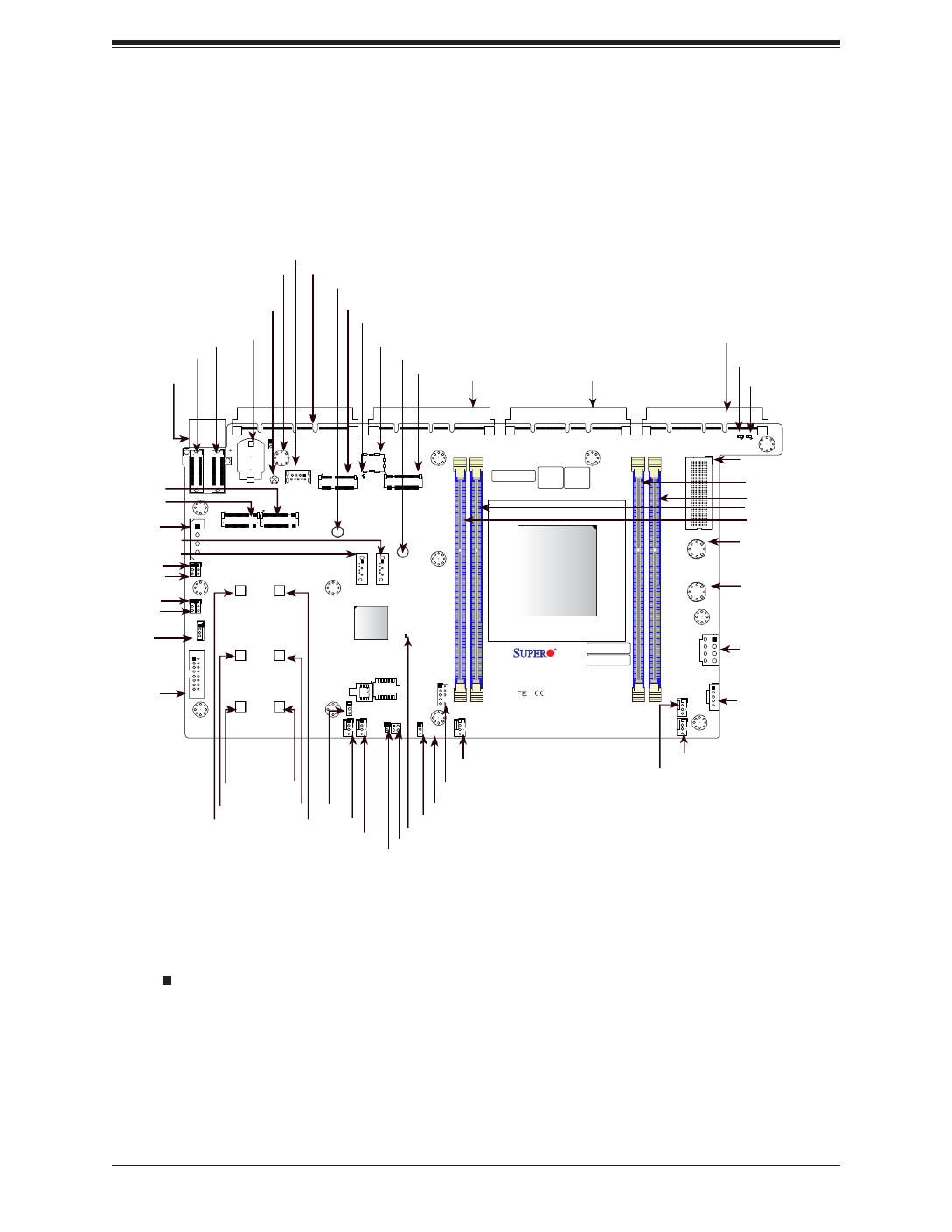
Notes:
• " " indicates the location of pin 1.
• Jumpers/LED indicators not indicated are used for testing only.
• Use only the correct type of onboard CMOS battery as specied by the manufacturer. Do
not install the onboard battery upside down to avoid possible explosion.
Figure 1-3. Motherboard Layout
1.5 Motherboard Layout
Below is a layout of the X11SDS-8C with the jumper, connector, and LED locations shown. See
the table on the following page for descriptions. For detailed descriptions, pinout information,
and jumper settings, refer to Chapter 4.
JUID
1
+
ABCDEFGH
1
S/N CODE
IPMI CODE
S/N LABEL BIOS LICENSE
1
C
A
C
A
X11SDS-8C
REV:1.01
DESIGNED IN USA
10G MAC
E-KEY B-KEY
M-KEY
M-KEY
SRW6
SRW1
PWR1
PWR2
JMD3 JMD4
JEDSFF1
JEDSFF2
JSLOT4 JSLOT3 JSLOT2 JSLOT1
JPWRST
JRK1
JP1
BT1
JBT1
JMA1
JSIM1
JL1
JUID
JVGA1
JPI2C1
S-SATA1
S-SATA2
JMD1 JMD2
JPWR1
MH5
MH7
MH8
MH13
MH9
MH3
MH6
MH4
MH12
MH11 MH10
JTPM1
PWR_LED1
BMC_HB_LED1
LED2
LED1
FAN4
FAN5
FAN1
FAN2
FAN3
MH2
MH1
JVRM1
JWD1
JBM1 JPME2
JPG1
JPT1
SRW7
SRW2
SRW4
SRW8
SRW3
SRW5
DIMMA1
DIMMB1
DIMME1
DIMMD1
JPT1
SoC
CPU
M.2-H_2M.2-H_1
USB0(3.0)
M.2-H_4M.2-H_3
JSLOT1
FAN4
BMC_HB_LED1
JMD2
DIMMB1
DIMMA1
FAN1
JVGA1
JP1
JSLOT2
JPI2C1
DIMME1
DIMMD1
JRK1
USB0
JSIM1
JPME2
JWD1
JMA1
JTPM1
JPWRST
JSLOT3
JVRM1
JBM1
JBT1 PWR_LED1
JSLOT4
LED1
S-SATA1
JPG1
LED2
JMD1
FAN2
FAN3
JPT1
FAN5
S-SATA2
SRW7
SRW2
SRW4
SRW8
SRW3
SRW5
JMD3
JMD4
JL1
BT1
JEDSFF1
JEDSFF2
JEDSFF3
SRW1
SRW6
PWR2
PWR1
JPWR1
JDBG1

17
Chapter 1: Introduction
Quick Reference Table for X11SDS-8C/12C/14C/16C
Jumper Description Default Setting
JBM1 IPMI Shared LAN Enable/Disable Pins 1-2 (Enabled)
JBT1 CMOS Clear Open: Normal
JPG1 Onboard VGA Enable/Disable Pins 1-2 (Enabled)
JPT1 Onboard TPM 2.0 Enable/Disable Pins 2-3 (Disabled)
JPME2 Manufacturing Mode Select Pins 1-2 (Normal)
JVRM1 VRM SMB Data (to BMC or PCH) Pins 1-2 (Normal)
JWD1 Watch Dog Timer Pins 1-2 (Reset)
LED Description Status
BMC_HB_LED1 BMC Heartbeat Blinking Green: BMC Normal
PWR_LED1 Power LED Solid Green: Power On
LED1 UID LED Solid Blue: Unit Identied
LED2 Overheat/PWR Fail/Fan Fail Solid Red: Overheat
Blinking Red: PWR Fail or Fan Fail
Connector Description
BT1 Onboard Battery
FAN1 - FAN5 CPU/System Fan Headers
JEDSFF1, JEDSFF2 EDSFF Short Header (Shared with M.2 M-Keys)
JL1 Chassis Intrusion Header
JMA1 Receptacle for AOM-SMF-TP4F
JMD1 M.2 Slot E-Key 2230 (PCI-E 3.0 x2/USB2.0)
JMD2 M.2 Slot B-Key 2242/3042 (PCI-E 3.0 x2/SATA3.0/USB3.0)
JMD3 M.2 Slot M-Key 2242/80/110 (PCI-E 3.0 x4/SATA3.0) Shared with JEDSFF1
JMD4 M.2 Slot M-Key 2242/80/110 (PCI-E 3.0 x4/SATA3.0) Shared with JEDSFF2
JP1 4-pin Power Connector for HDD use
JPI2C1 Power I2C System Management Bus (Power SMB) Header
JPWR1 8-pin +12V DC Power Connector
JPWRST Power and Reset Button
JRK1 Intel RAID Key Header (supporting AIOM Slots)
JSIM1 Nano SIM Card Socket
JSLOT1 - JSLOT4 Supermicro Advanced I/O Module (AIOM)
*Please unplug power before removing/installing module cards
JTPM1 Trusted Platform Module (TPM)/Port 80 Connector
JUID UID Switch Header
JVGA1 VGA Header
PWR1 - PWR2 Bus Bar Connector (to AOM-SMF-TP4F)
S-SATA1 - S-SATA2 SATA 3.0 Ports
SRW1 - SRW8 M.2 Holding Screws
USB0 USB3.0 Gen 1 Type A Header

18
SuperServer 1019D-(12C/14C/16C-)FRN5TP User's Manual
Quick Reference Table for AOM-SMF-TP4F
Jumper Description Default Setting
JPTG1 10G LAN Enable/Disable Pins 1-2 (Enabled)
LED Description Status
LED1 Power LED Solid Green: Power On
Connector Description
J1 Front Control Panel Cable Header
JCOM1 Serial Console Port and USB 3.0 Port
JLAN1 1G RJ45 Port and USB 3.0 Port
JLAN2 Dual 10G RJ45 Ports
JMA1 Receptacle for X11SDS-8C/16C
JSFP1 Dual 10G SFP+ Ports
JUSB1 Micro USB Serial Console Port (Shared with Serial Console Port)
PWR1 - PWR2 Bus Bar Connector
BAR CODE
DESIGNED IN USA
AOM-SMF-TP4F
REV:1.02
PRESS FIT
A
C
A
C
A
C
A
C
A
C
1
PWR1PWR2
JSFP1
JLAN2
LEDT1
LEDT2
LEDT3
LEDT4
LED1
JCOM1 JL AN1
JPTG1
MH3
MH2
MH4
MH5
J1
MH1
MH6
PWR2
JPTG1
PWR1
LED1
J1
JCOM1
JLAN1
JLAN2
JSFP1
ABCDEFGH
1
5
10
15
20
25
30
1
JMA1
J4 J5
JUSB1
JMA1
JUSB1
Top View Bottom View
Figure 1-4. AOM-SMF-TP4F Add-on Card Layout
(not drawn to scale)
19
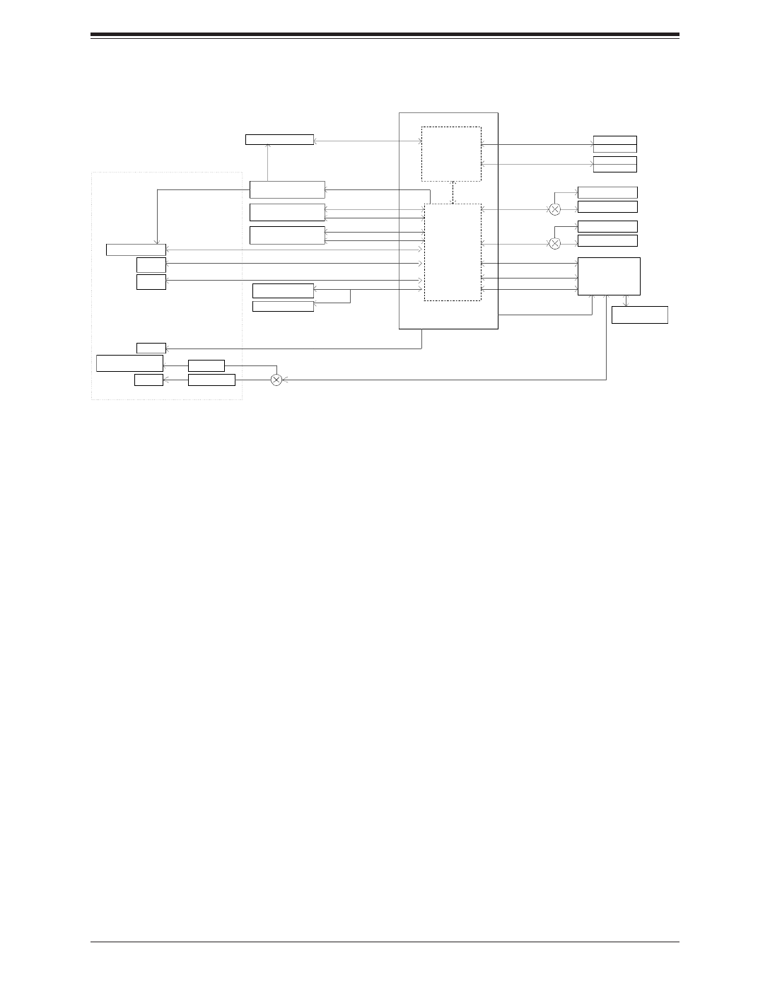
Chapter 1: Introduction
Figure 1-5. System on Chip Chipset: System Block Diagram
Note: This is a general block diagram and may not exactly represent the features on your
motherboard. See the System Specications appendix for the actual specications of your
motherboard.
COMN IC-S
VGA/COM
(KVM FOR DBG )
PCIe3.0 x 1
CBM
ASP2500
USB2.0 X 1
ESPI
M.2 X4
PCIe3.0 X4
M.2 X4
EDSFF X4
MUX
MUX
MUX
NC-SI FOR X55 7
USB 2.0 HU B
USB2.0 X 1
DEFAULT
CPU D-2146-N T
USB2.0 X 4
JMP TO DISABL E
DEFAULT
DEFAULT
U TAR
JMP TO DISABL E
TRANCEIVER U TAR
A FOM-SMF-TP4
4x SIOM (2x4 EACH )
PCIe3.0 8 x4
USB3.0 X 2
SPI
2 SUSB 3.0 PORT
PCH
2666/2400/2133/1866 MH z
PWR_I/O BOAR D
CONNECTOR
DDR4
CPU
X C11SDS-8
DIMMB(Far)
D AIMM
DDR4
DIMME(Far)
D DIMM
2666/2400/2133/1866 MH z
FLASH SPI 256M b
DMI
SPI
TPM (ONBOARD )
SATA II I
2 SsSATA PORT
SATA II I
PCIe3.0 2/SATA II x I
2 SM.2 E/B KEY PORT
(PCIE or SATA )
PCIe3.0 2/SATA II x I
CS4227
X 755
KR PORT 2, 3
KR PORT 0, 1
R 5J4
EDSFF X4
PCIe3.0 X4
CPU CONSOL E
MCP2221
PCIe X1
I 021
NC-SI
TO uUSB TYPE AB U TUSB AR
USB2.0 X 2
15TOGO

SuperServer 1019D-(12C/14C/16C-)FRN5TP User's Manual
20
Chapter 2
Installation in a Rack
2.1 Overview
This chapter provides advice and instructions for mounting your system in a rack.
Caution: Electrostatic Discharge (ESD) can damage electronic components. To pre-
vent such damage to PCBs (printed circuit boards), it is important to use a grounded
wrist strap, handle all PCBs by their edges, and keep them in anti-static bags when
not in use.
2.2 Preparing for Setup
The box in which the system was shipped should include the hardware needed to install it
into the rack. Please note the precautions in this chapter and Appendix B.
Choosing a Setup Location
• The system should be situated in a clean, dust-free area that is well ventilated. Avoid areas
where heat, electrical noise, and electromagnetic elds are generated. It will also require
a grounded AC power outlet nearby.
• Leave enough clearance in front of the rack so that you can open the front door completely
(~25 inches) and approximately 30 inches of clearance in the back of the rack to allow
sufcient space for airow and access when servicing.
• This product should be installed only in a Restricted Access Location (dedicated equipment
rooms, service closets, etc.).
• This product is not suitable for use with visual display workplace devices according to §2
of the German Ordinance for Work with Visual Display Units.
Rack Precautions
• Ensure that the leveling jacks on the bottom of the rack are extended to the oor so that
the full weight of the rack rests on them.
• In single rack installations, stabilizers should be attached to the rack.

21
Chapter 2 Installation in a Rack
• In multiple rack installations, the racks should be coupled together.Always make sure the
rack is stable before extending a server or other component from the rack.
• Extend only one server or component at a time - extending two or more simultaneously
may cause the rack to become unstable.
Server Precautions
• Review the electrical and general safety precautions in Appendix B.
• Determine the placement of each component in the rack you install the rails.before
• Install the heaviest server components at the bottom of the rack rst and then work your
way up.
• Use a regulating uninterruptible power supply (UPS) to protect the server from power
surges and voltage spikes and to keep your system operating in case of a power failure.
• Allow any drives and power supplies to cool before touching them.
• When not servicing, always keep the front door of the rack and all covers/panels on the
servers closed to maintain proper cooling.
Rack Mounting Considerations
Ambient Operating Temperature
If installed in a closed or multi-unit rack assembly, the ambient operating temperature of
the rack environment may be greater than the room's ambient temperature. Therefore,
consideration should be given to installing the equipment in an environment compatible with
the manufacturer’s maximum rated ambient temperature (Tmra).
Reduced Airow
Equipment should be mounted into a rack so that the amount of airow required for safe
operation is not compromised.
Mechanical Loading
Equipment should be mounted into a rack so that a hazardous condition does not arise due
to uneven mechanical loading.

SuperServer 1019D-(12C/14C/16C-)FRN5TP User's Manual
22
Circuit Overloading
Consideration should be given to the connection of the equipment to the power supply circuitry
and the effect that any possible overloading of circuits might have on overcurrent protection
and power supply wiring. Appropriate consideration of equipment nameplate ratings should
be used when addressing this concern.
Reliable Ground
A reliable ground must be maintained at all times. To ensure this, the rack itself should be
grounded. Particular attention should be given to power supply connections other than the
direct connections to the branch circuit (e.g., the use of power strips, etc.).
To prevent bodily injury when mounting or servicing this unit in a rack, you must take
special precautions to ensure that the system remains stable. The following guidelines
are provided to ensure your safety:
• This unit should be mounted at the bottom of the rack if it is the only unit in the rack.
• When mounting this unit in a partially lled rack, load the rack from the bottom to the top
with the heaviest component at the bottom of the rack.
• If the rack is provided with stabilizing devices, install the stabilizers before mounting or
servicing the unit in the rack.
• Slide rail mounted equipment is not to be used as a shelf or a work space.

23
Chapter 2 Installation in a Rack
2.3 Installing the Rails
There are a variety of rack units on the market, which may require a slightly different assembly
procedure. Also refer to the installation instructions that came with the rack.
This rail set ts a rack between 26" and 33.5" deep.
Identifying the Sections of the Rack Rails
The chassis package includes two rack rail assemblies in the rack mounting kit. Each as-
sembly consists of two sections: an inner xed chassis rail that secures directly to the server
chassis and an outer xed rack rail that secures directly to the rack itself.
Inner Rails
(Inner rail is preinstalled
on the chassis)
Inner Rail Locking Tabs
Figure 2-1. Identifying the Sections of the Inner Rails
Locking Tabs
Both chassis rails have a locking tab. The tabs lock the server into place when installed and
pushed fully into the rack. These tabs also lock the server in place when fully extended from
the rack. This prevents the server from coming completely out of the rack when you pull it
out for servicing.

25
Chapter 2 Installation in a Rack
Installing the Outer Rack Rails
Outer rails attach to the server rack and hold the server in place. The outer rails for the
SC103-R407B chassis extend between 30 inches and 33 inches.
Installing the Outer Rails to the Rack
1. Attach the short bracket to the outside of the long bracket. Align the pins of the rail with
the slides. The ends of each bracket must angle in the same direction.
2. Adjust both the short and long brackets to the proper distance so that the rail ts
snuggly into the rack.
3. Secure the long bracket to the front side of the outer rail with two M5 screws and the
short bracket to the rear side of the outer rail with three M5 screws.
4. Repeat steps 1-3 for the remaining outer rail.
Secure to the
Front of the Rack
Secure to the
Rear of the Rack
Attach Outer Rails
Together
Figure 2-3. Assembling the Outer Rails

SuperServer 1019D-(12C/14C/16C-)FRN5TP User's Manual
26
2.4 Installing the Chassis into a Rack
Once rails are attached to the chassis and the rack, you can install the server.
Warning: Mounting the system into the rack requires at least two people to support the
chassis during installation. Please follow safety recommendations printed on the rails.
Installing the Chassis into a Rack
1. Conrm that the chassis includes the inner rails and rail extensions. Also, conrm that
the outer rails are installed on the rack.
2. Align the chassis rails with the front of the rack rails.
3. Slide the chassis rails into the rack rails, keeping the pressure even on both sides.
(It may be necessary to depress the locking tabs when inserting.) When the server
has been pushed completely into the rack, the locking tabs will "click" into the locked
position.
4. (Optional) Insert and tighten the thumbscrews that hold the front of the server to the
rack.
Figure 2-4. Installing the Server into a Rack
Note: The gures above are for illustrative purposes only and may differ from your actual
unit. Always install servers into racks from the bottom up.
Stability hazard. The rack stabilizing mechanism must be in place, or the rack must
be bolted to the oor before you slide the unit out for servicing. Failure to stabilize the
rack can cause the rack to tip over.

27
Chapter 3 Maintenance and Component Installation
Chapter 3
Maintenance and Component Installation
This chapter provides instructions on installing and replacing main system components. To
prevent compatibility issues, only use components that match the specications and/or part
numbers given.
Installation or replacement of most components require that power rst be removed from the
system. Please follow the procedures given in each section.
3.1 Removing Power
Use the following procedure to ensure that power has been removed from the system. This
step is necessary when removing or installing non hot-swap components.
1. Use the operating system to power down the system.
2. After the system has completely shut-down, disconnect the AC power cord(s) from the
power strip or outlet. (If your system has more than one power supply, remove the AC
power cords from all power supplies.)
3. Disconnect the power cord(s) from the power supply/supplies.
SuperServer 1019D-(12C/14C/16C-)FRN5TP User's Manual
28
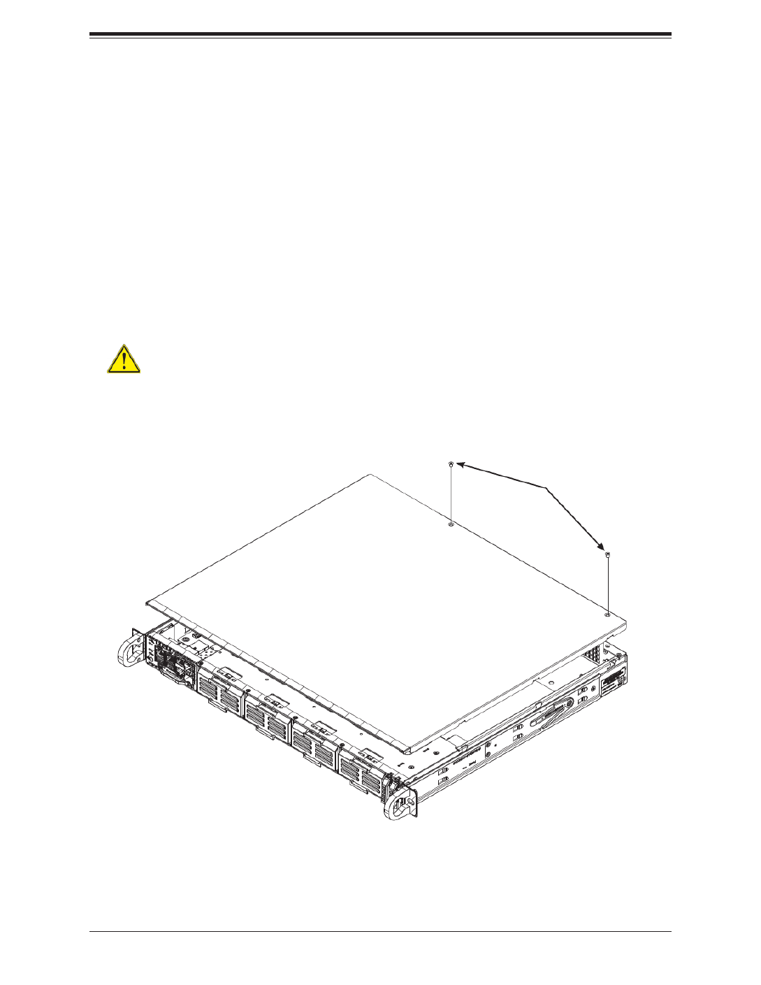
Figure 3-1. Removing the Chassis Cover
3.2 Accessing the System
Removing the Chassis Cover
You can access some chassis components, such as fans, by removing the cover.
Removing the Top Cover
1. Remove the power from the system as described in Section 3.1.
2. Remove the two screws securing the cover to the chassis. See Figure 3-1.
3. Slide the cover back toward the rear of the chassis.
4. Lift the cover from the chassis.
Screws
Caution: Except for short periods of time, do not operate the server without the cover
in place. The chassis cover must be in place to allow for proper airow and to prevent
overheating.

29
Chapter 3 Maintenance and Component Installation
3.3 Motherboard Components
Memory Installation
Memory Support
The X11SDS-8C/12C/14C/16C motherboard supports up to 512GB of ECC LRDIMM or
256GB ECC RDIMM (with DDR4 speeds up to 2133MHz for X11SDS-8C, X11SDS-12C, and
X11SDS-14C and up to 2400MHz for X11SDS-16C) in four memory slots. Populating these
DIMM slots with memory modules of the same type and size will result in interleaved memory,
which will improve memory performance.
Check the Supermicro website for possible updates to memory support.
DIMM Module Population Conguration
For optimal memory performance, follow the table below when populating memory.
Memory Population (Balanced)
DIMMA1 DIMMB1 DIMMD1 DIMME1 Total System
Memory
4GB 4GB 8GB
8GB 8GB
8GB 8GB 16GB
4GB 4GB 4GB 4GB 16GB
8GB 8GB 8GB 24GB
8GB 8GB 8GB 8GB 32GB
16GB 16GB 32GB
16GB 16GB 16GB 48GB
16GB 16GB 16GB 16GB 64GB
32GB 32GB 64GB
32GB 32GB 32GB 96GB
32GB 32GB 32GB 32GB 128GB
64GB 64GB 128GB
64GB 64GB 64GB 192GB
64GB 64GB 64GB 64GB 256GB
126GB 128GB 256GB
128GB 128GB 128GB 128GB 512GB

SuperServer 1019D-(12C/14C/16C-)FRN5TP User's Manual
30
DIMM Module Population Sequence
When installing memory modules, the DIMM slots should be populated in the following order:
DIMMA1, DIMMB1, DIMMD1, DIMME1.
• Always use DDR4 DIMM modules of the same type and speed.
• Mixed DIMM speeds can be installed. However, all DIMMs will run at the speed of the
slowest DIMM.
• The motherboard will support odd-numbered modules (one or three modules installed).
However, for best memory performance, install DIMM modules in pairs to activate memory
interleaving.
1
+
ABCDEFGH
1
S/N CODE
IPMI CODE
S/N LABEL BIOS LICENSE
1
C
A
C
A
X11SDS-8C
REV:1.01
DESIGNED IN USA
10G MAC
E-KEY B-KEY
M-KEY
M-KEY
SRW6
SRW1
PWR1
PWR2
JMD3 JMD4
JEDSFF1
JEDSFF2
JSLOT4 JSLOT3 JSLOT2 JSLOT1
JPWRST
JRK1
JP1
BT1
JBT1
JMA1
JSIM1
JL1
JUID
JVGA1
JPI2C1
S-SATA1
S-SATA2
JMD1 JMD2
JPWR1
MH5
MH7
MH8
MH13
MH9
MH3
MH6
MH4
MH12
MH11 MH10
JTPM1
PWR_LED1
BMC_HB_LED1
LED2
LED1
FAN4
FAN5
FAN1
FAN2
FAN3
MH2
MH1
JVRM1
JWD1
JBM1 JPME2
JPG1
JPT1
SRW7
SRW2
SRW4
SRW8
SRW3
SRW5
DIMMA1
DIMMB1
DIMME1
DIMMD1
JPT1
SoC
CPU
M.2-H_2M.2-H_1
USB0(3.0)
M.2-H_4M.2-H_3
DIMMB1
DIMMA1
DIMME1
DIMMD1
SuperServer 1019D-(12C/14C/16C-)FRN5TP User's Manual
32
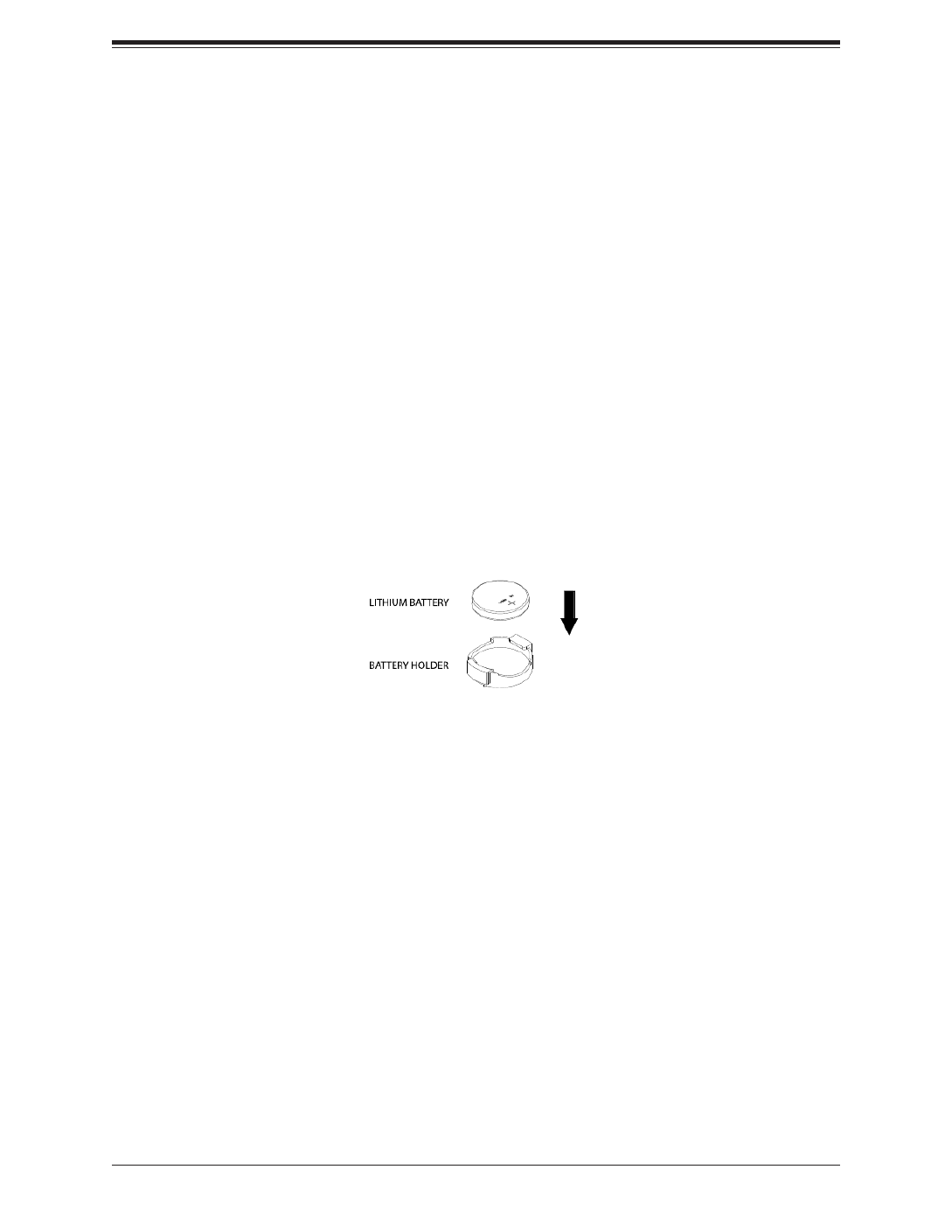
Warning: There is a danger of explosion if the onboard battery is installed upside down (which
reverses its polarities). This battery must be replaced only with the same or an equivalent type
recommended by the manufacturer (CR2032).
Figure 3-2. Installing the Onboard Battery
Motherboard Battery
The motherboard uses CMOS memory to retain BIOS settings when system power is
removed. This memory is powered by a lithium battery residing on the motherboard.
Replacing the Battery
1. Remove power from the system as described in section 3.1 and remove the node from
the chassis.
2. Push aside the small clamp that covers the edge of the battery. When the battery is
released, lift it out of the holder.
3. To insert a new battery, slide one edge under the lip of the holder with the positive (+)
side facing up. Then push the other side down until the clamp snaps over it.
Note: Handle used batteries carefully. Do not damage the battery in any way; a damaged
battery may release hazardous materials into the environment. Do not discard a used battery
in the garbage or a public landll. Please comply with the regulations set up by your local
hazardous waste management agency to dispose of your used battery properly.

33
Chapter 3 Maintenance and Component Installation
3.4 Chassis Components
AIOM and EDSFF "Ruler" Device Bays
The SC103 supports four AIOM modules (Advanced I/O Module) and two EDSFF (Enterprise
and Datacenter SSD Form Factor) drives, also referred to as a "ruler". These devices may
be purchased separately from the chassis. This section explains how to insert the AIOM and
EDSFF in the chassis.
Removing the Dummy Device from the Chassis
1. Remove the dummy AIOM insert from the front side of the chassis by holding the lever
and gently pulling the insert out from the chassis.
2. A Supermicro AIOM network module (such as AOC-AG-i8, sold separately) may now be
installed into the slot.
Caution: The AIOM slot and device are NOT hot-swappable. Please disconnect the
power from the system before attempting to install or remove any AIOM network
adapter.
Figure 3-3. Removing the Dummy AIOM Insert
Pull out lever
Dummy AIOM Insert

SuperServer 1019D-(12C/14C/16C-)FRN5TP User's Manual
34
Inserting the AIOM Module
1. Power down the system as described in section 3-1. Once the dummy AIOM insert is
removed, the Supermicro AIOM network module may be installed.
2. Gently slide the AIOM module into the slot by aligning the PCB edge into the chassis
rail.
3. Once the AIOM module is inserted, gently push the module by the metal bracket, until
the module is fully engaged into the chassis.
Figure 3-4. Inserting the AIOM Module
Produktspecifikationer
| Varumärke: | Supermicro |
| Kategori: | Server |
| Modell: | SuperServer 1019D-14C-FRN5TP |
Behöver du hjälp?
Om du behöver hjälp med Supermicro SuperServer 1019D-14C-FRN5TP ställ en fråga nedan och andra användare kommer att svara dig
Server Supermicro Manualer

31 Januari 2025
25 Januari 2025
9 Januari 2025
29 December 2024
29 December 2024
29 December 2024
29 December 2024
29 December 2024
29 December 2024
29 December 2024
Server Manualer
- Server Sony
- Server HP
- Server Medion
- Server Toshiba
- Server Abus
- Server Acer
- Server Allnet
- Server Apc
- Server Acti
- Server Hikvision
- Server Asus
- Server SilverStone
- Server Megasat
- Server Maxdata
- Server Lenovo
- Server Black Box
- Server Tripp Lite
- Server Axis
- Server Gigabyte
- Server Nec
- Server Technics
- Server Cisco
- Server AVerMedia
- Server Matrox
- Server Flir
- Server Fujitsu
- Server Digitus
- Server Kathrein
- Server Asrock
- Server Linksys
- Server Buffalo
- Server GeoVision
- Server Netgear
- Server LevelOne
- Server QNAP
- Server LaCie
- Server Dell
- Server Valcom
- Server Asustor
- Server Planet
- Server ZyXEL
- Server Western Digital
- Server Intel
- Server Fantec
- Server MSI
- Server D-Link
- Server Freecom
- Server Eaton
- Server Seagate
- Server Iomega
- Server Synology
- Server Elac
- Server Blackmagic Design
- Server ATen
- Server Veritas
- Server Digi
- Server Revox
- Server Conceptronic
- Server Gefen
- Server Luxman
- Server Quantum
- Server Areca
- Server SEH
- Server Ibm
- Server Provision ISR
- Server Sonnet
- Server Monacor
- Server TAIDEN
- Server Moxa
- Server Smart-AVI
- Server StarTech.com
- Server SIIG
- Server Advantech
- Server Extron
- Server KanexPro
- Server Avocent
- Server Intellinet
- Server Teradek
- Server Vimar
- Server Silex
- Server Kramer
- Server Hanwha
- Server In Win
- Server Lindy
- Server Ernitec
- Server Sun
- Server Atlona
- Server MvixUSA
- Server Dual Bay
- Server Raidsonic
- Server EMC
- Server AMX
- Server Rocstor
- Server Infortrend
- Server Opengear
- Server G-Technology
- Server EXSYS
- Server Raritan
- Server Chenbro Micom
- Server Middle Atlantic
- Server Mr. Signal
- Server Atlantis Land
- Server C2G
- Server Lantronix
- Server Promise Technology
- Server HGST
- Server IStarUSA
- Server NETSCOUT
- Server Mobotix
- Server Origin Storage
Nyaste Server Manualer
9 April 2025
3 April 2025
2 April 2025
2 April 2025
1 April 2025
29 Mars 2025
29 Mars 2025
29 Mars 2025
10 Mars 2025
10 Mars 2025