Supermicro SuperServer 2028TP-HC0R Bruksanvisning
Supermicro
Server
SuperServer 2028TP-HC0R
Läs nedan 📖 manual på svenska för Supermicro SuperServer 2028TP-HC0R (142 sidor) i kategorin Server. Denna guide var användbar för 7 personer och betygsatt med 4.5 stjärnor i genomsnitt av 2 användare
Sida 1/142

USER'S MANUAL
Revision 1.0a
SUPERSERVER®
2028TP-HC0R
2028TP-HC0TR
2028TP-HC0FR

The information in this User’s Manual has been carefully reviewed and is believed to be accurate.
The vendor assumes no responsibility for any inaccuracies that may be contained in this document,
makes no commitment to update or to keep current the information in this manual, or to notify any
person or organization of the updates. Please Note: For the most up-to-date version of this
manual, please see our web site at www.supermicro.com.
Super Micro Computer, Inc. ("Supermicro") reserves the right to make changes to the product
described in this manual at any time and without notice. This product, including software and
documentation, is the property of Supermicro and/or its licensors, and is supplied only under a
license. Any use or reproduction of this product is not allowed, except as expressly permitted by
the terms of said license.
IN NO EVENT WILL SUPERMICRO BE LIABLE FOR DIRECT, INDIRECT, SPECIAL, INCIDENTAL,
SPECULATIVE OR CONSEQUENTIAL DAMAGES ARISING FROM THE USE OR INABILITY TO
USE THIS PRODUCT OR DOCUMENTATION, EVEN IF ADVISED OF THE POSSIBILITY OF
SUCH DAMAGES. IN PARTICULAR, SUPERMICRO SHALL NOT HAVE LIABILITY FOR ANY
HARDWARE, SOFTWARE, OR DATA STORED OR USED WITH THE PRODUCT, INCLUDING THE
COSTS OF REPAIRING, REPLACING, INTEGRATING, INSTALLING OR RECOVERING SUCH
HARDWARE, SOFTWARE, OR DATA.
Any disputes arising between manufacturer and customer shall be governed by the laws of Santa
Clara County in the State of California, USA. The State of California, County of Santa Clara shall
be the exclusive venue for the resolution of any such disputes. Super Micro's total liability for all
claims will not exceed the price paid for the hardware product.
FCC Statement: This equipment has been tested and found to comply with the limits for a Class
A digital device pursuant to Part 15 of the FCC Rules. These limits are designed to provide
reasonable protection against harmful interference when the equipment is operated in a commercial
environment. This equipment generates, uses, and can radiate radio frequency energy and, if not
installed and used in accordance with the manufacturer’s instruction manual, may cause harmful
interference with radio communications. Operation of this equipment in a residential area is likely
to cause harmful interference, in which case you will be required to correct the interference at your
own expense.
California Best Management Practices Regulations for Perchlorate Materials: This Perchlorate
warning applies only to products containing CR (Manganese Dioxide) Lithium coin cells. “Perchlorate
Material-special handling may apply. See www.dtsc.ca.gov/hazardouswaste/perchlorate”
WARNING: Handling of lead solder materials used in this
product may expose you to lead, a chemical known to
the State of California to cause birth defects and other
reproductive harm.
Manual Revision 1.0a
Release Date: February 08, 2018
Unless you request and receive written permission from Super Micro Computer, Inc., you may not
copy any part of this document.
Information in this document is subject to change without notice. Other products and companies
referred to herein are trademarks or registered trademarks of their respective companies or mark
holders.
Copyright © 2018 by Super Micro Computer, Inc.
All rights reserved.
Printed in the United States of America

iii
Preface
Preface
About This Manual
This manual is written for professional system integrators and PC technicians.
It provides information for the installation and use of the SuperServer
2028TP-HC0R/HC0TR/HC0FR. Installation and maintainance should be performed
by experienced technicians only.
The SuperServer 2028TP-HC0R/HC0TR/HC0FR is a high-end server based
on the SC217HQ+-R2K02B 2U rackmount chassis and the dual processor
X10DRT-P/PT/PIBF serverboard. All models have four serverboard nodes with six
hot-swap Hard Disk Drives (HDD) each per node.
Manual Organization
Chapter 1: Introduction
The rst chapter provides a checklist of the main components included with
the server system and describes the main features of the X10DRT-P/PT/PIBF
serverboard and the SC217HQ+-R2K02B chassis.
Chapter 2: Server Installation
This chapter describes the steps necessary to install the SuperServer
2028TP-HC0R/HC0TR/HC0FR into a rack and check out the server conguration
prior to powering up the system. If your server was ordered without processor and
memory components, this chapter will refer you to the appropriate sections of the
manual for their installation.
Chapter 3: System Interface
Refer here for details on the system interface, which includes the functions and
information provided by the control panel on the chassis as well as other LEDs
located throughout the system.
Chapter 4: Standardized Safety Warnings
You should thoroughly familiarize yourself with this chapter for a general overview
of safety precautions that should be followed when installing and servicing the
SuperServer 2028TP-HC0R/HC0TR/HC0FR.
Chapter 5: Advanced Serverboard Setup
Chapter 5 provides detailed information on the X10DRT-P/PT/PIBF serverboard,
including the locations and functions of connections, headers and jumpers. Refer
to this chapter when adding or removing processors or main memory and when
reconguring the serverboard.

SUPERSERVER 2028TP-HC0R/HC0TR/HC0FR USER'S MANUAL
iv
Chapter 6: Advanced Chassis Setup
Refer to Chapter 6 for detailed information on the SC217HQ+-R2K02B server
chassis. You should follow the procedures given in this chapter when installing,
removing or reconguring SATA or peripheral drives and when replacing system
power supply units and cooling fans.
Chapter 7: BIOS
The BIOS chapter includes an introduction to BIOS and provides detailed information
on running the CMOS Setup Utility.
Appendix A: BIOS Error Beep Codes
Appendix B: System Specications
Appendix C: Chinese Safety Warnings

v
SUPERSERVER 2028TP-HC0R/HC0TR/HC0FR USER'S MANUAL
Notes

vi
Table of Contents
Chapter 1 Introduction
1-1 Overview ......................................................................................................... 1-1
1-2 Serverboard Features ..................................................................................... 1-2
Processors 1-2 ......................................................................................................
Memory 1-2 ...........................................................................................................
SAS 1-2 .................................................................................................................
SATA .............................................................................................................. 1-2
PCI Expansion Slots ....................................................................................... 1-3
Onboard Controllers/Ports .............................................................................. 1-3
Graphics Controller ......................................................................................... 1-3
InniBand ........................................................................................................ 1-3
Other Features ................................................................................................ 1-3
1-3 Server Chassis Features ................................................................................ 1-4
System Power ................................................................................................. 1-4
Front Control Panel ......................................................................................... 1-4
Cooling System ............................................................................................... 1-4
Air Shrouds ..................................................................................................... 1-4
Mounting Rails ................................................................................................ 1-4
1-5 Contacting Supermicro .................................................................................... 1-6
1-6 2U Twin2: System Notes ................................................................................. 1-7
Nodes 1-7 ..............................................................................................................
System Power ................................................................................................. 1-7
Hard Drive Backplane/Drives .......................................................................... 1-7
Chapter 2 Server Installation
2-1 Overview ......................................................................................................... 2-1
2-2 Unpacking the System .................................................................................... 2-1
2-3 Preparing for Setup ......................................................................................... 2-1
Choosing a Setup Location ............................................................................. 2-2
2-4 Warnings and Precautions .............................................................................. 2-2
Rack Precautions ............................................................................................ 2-2
Server Precautions .......................................................................................... 2-2
Rack Mounting Considerations ....................................................................... 2-3
Ambient Operating Temperature ................................................................ 2-3
Reduced Airow ......................................................................................... 2-3
Mechanical Loading ................................................................................... 2-3
Circuit Overloading ..................................................................................... 2-3
Reliable Ground ......................................................................................... 2-3
SUPERSERVER 2028TP-HC0R/HC0TR/HC0FR USER'S MANUAL

vii
2-5 Installing the System into a Rack ................................................................... 2-4
Identifying the Sections of the Rack Rails ...................................................... 2-4
Locking Tabs ................................................................................................... 2-5
Releasing the Inner Rail ................................................................................. 2-5
Installing The Inner Rails on the Chassis ....................................................... 2-6
Installing the Outer Rails on the Rack ............................................................ 2-7
Standard Chassis Installation ......................................................................... 2-8
Chapter 3 System Interface
3-1 Overview ......................................................................................................... 3-1
3-2 Control Panel Button ....................................................................................... 3-2
Power 3-2 ..............................................................................................................
UID 3-2 ..................................................................................................................
3-3 Control Panel LEDs ........................................................................................ 3-2
Alert 3-2 .................................................................................................................
NIC 3-3 ..................................................................................................................
3-4 Hard Drive Carrier LEDs ................................................................................. 3-3
Chapter 4 Standardized Warning Statements for AC Systems
4-1 About Standardized Warning Statements ....................................................... 4-1
Warning Denition ........................................................................................... 4-1
Installation Instructions .................................................................................... 4-4
Circuit Breaker ................................................................................................ 4-5
Power Disconnection Warning ........................................................................ 4-6
Equipment Installation ..................................................................................... 4-8
Restricted Area ................................................................................................ 4-9
Battery Handling ............................................................................................ 4-10
Redundant Power Supplies .......................................................................... 4-12
Backplane Voltage ........................................................................................ 4-13
Comply with Local and National Electrical Codes ........................................ 4-14
Product Disposal ........................................................................................... 4-15
Hot Swap Fan Warning ................................................................................. 4-16
Power Cable and AC Adapter ...................................................................... 4-18
Chapter 5 Advanced Serverboard Setup
5-1 Handling the Serverboard ............................................................................... 5-1
Precautions 5-1 .....................................................................................................
Unpacking 5-1 .......................................................................................................
5-2 Connecting Cables .......................................................................................... 5-2
Connecting Data Cables ................................................................................. 5-2
5-3 Rear I/O Ports ................................................................................................. 5-3
5-4 Processor and Heatsink Installation................................................................ 5-4
Table of Contents

viii
Installing a Passive CPU Heatsink ................................................................. 5-7
Removing the Heatsink ................................................................................... 5-8
5-5 Installing Memory ............................................................................................ 5-9
Memory Support .............................................................................................. 5-9
5-6 Adding PCI Expansion Cards ........................................................................5-11
5-7 Serverboard Details ...................................................................................... 5-12
X10DRT-P/PT/PIBF Quick Reference ........................................................... 5-13
5-8 Connector Denitions .................................................................................... 5-14
5-9 Jumper Settings ............................................................................................ 5-17
Explanation of Jumpers ................................................................................ 5-17
5-10 Onboard Indicators ........................................................................................ 5-19
5-11 PCI-Express and SATA Connections ............................................................ 5-21
5-12 Installing Software ......................................................................................... 5-22
SuperDoctor® 5 ............................................................................................ 5-23
5-13 Onboard Battery ............................................................................................ 5-24
Chapter 6 Advanced Chassis Setup
6-1 Static-Sensitive Devices .................................................................................. 6-1
Precautions 6-1 .....................................................................................................
Unpacking 6-1 .......................................................................................................
6-2 Control Panel .................................................................................................. 6-2
6-3 Chassis Cover ................................................................................................. 6-3
6-4 Air Shrouds ..................................................................................................... 6-4
6-5 Checking the Airow ....................................................................................... 6-5
6-6 System Fans ................................................................................................... 6-5
Optional Fan Congurations ........................................................................... 6-5
6-7 Removing and Installing the Backplane .......................................................... 6-8
Removing the Backplane ................................................................................ 6-8
Installing the Backplane ................................................................................ 6-10
6-8 Installing the Serverboard ..............................................................................6-11
I/O Shield .......................................................................................................6-11
Permanent and Optional Standoffs ................................................................6-11
6-9 Adapter Card Replacement........................................................................... 6-14
Expansion Card/PCI Slot Setup .................................................................... 6-15
Installing the Riser Card ............................................................................... 6-15
6-10 Drive Bay Installation/Removal ..................................................................... 6-17
Accessing the Drive Bays ............................................................................. 6-17
6-11 Power Supply ................................................................................................ 6-20
Power Supply Replacement .......................................................................... 6-20
SUPERSERVER 2028TP-HC0R/HC0TR/HC0FR USER'S MANUAL

Chapter 7 BIOS
7-1 Introduction ...................................................................................................... 7-1
Starting BIOS Setup Utility .............................................................................. 7-1
How To Change the Conguration Data ......................................................... 7-1
How to Start the Setup Utility ......................................................................... 7-2
7-2 Main Setup ...................................................................................................... 7-2
7-3 Advanced Setup Congurations...................................................................... 7-4
7-4 Event Logs .................................................................................................... 7-32
7-5 IPMI ............................................................................................................... 7-34
7-6 Security Settings ........................................................................................... 7-36
7-7 Boot Settings ................................................................................................. 7-37
7-8 Save & Exit ................................................................................................... 7-39
Appendix A BIOS Error Beep Codes
Appendix B System Specications
Appendix C Chinese Safety Warnings
ix
Table of Contents

x
Notes
SUPERSERVER 2028TP-HC0R/HC0TR/HC0FR USER'S MANUAL

Chapter 1
Introduction
1-1 Overview
The SuperServer 2028TP-HC0R/HC0TR/HC0FR is a high-end server comprised
of two main subsystems: the SC217HQ+-R2K02B 2U server chassis and the
X10DRT-P/PT/PIBF dual processor serverboard in four hot-swap nodes. Please
refer to our website for information on operating systems that have been certied
for use with the system (www.supermicro.com).
In addition to the serverboard and chassis, various hardware components have
been included with the SuperServer 2028TP-HC0R/HC0TR/HC0FR server, as
listed below:
• Heat Sinks
Four 1U passive CPU heat sinks for rear CPU (SNK-P0047PSM)
Four 1U passive CPU heat sinks w/narrow ILM (SNK-P0057PS)
• Four mylar air shrouds (MCP-310-21702-0B)
• Four 80x80x38mm cooling fans (FAN-0136L4)
• SATA/SAS Backplane
Four HD backplanes (BPN-ADP-S3008L-L6IP-O-P)
One SAS backplane HDD (BPN-SAS3-217HQ)
Twenty-four hot-swap 2.5" HDD trays (MCP-220-00047-0B)
• Four Riser cards (RSC-R1UTP-E16R-O-P)
• One Rackmount rail kit (MCP-290-00053-0N)
Note: For your system to work properly, please follow the links below to download
all necessary drivers/utilities and the user’s manual for your server.
• Supermicro product manuals: http://www.supermicro.com/support/manuals/
• Product drivers and utilities: ftp://ftp.supermicro.com
• Product safety info: http://www.supermicro.com/about/policies/safety_
information.cfm
Chapter 1: Introduction
1-1

1-2
SUPERSERVER 2028TP-HC0R/HC0TR/HC0FR USER'S MANUAL
1-2 Serverboard Features
At the heart of the SuperServer 2028TP-HC0R/HC0TR/HC0FR lies the
X10DRT-P/PT/PIBF, a dual processor serverboard based on the Intel®
PCH C612 chipset and designed to provide maximum performance. Four of these
serverboards can be mounted in the SC217HQ+-R2K02B chassis.
The sections below cover the main features of the X10DRT-P/PT/PIBF serverboard
(see Figure 1-1 for a block diagram of the chipset).
Processors
The X10DRT-P/PT/PIBF supports single or dual Intel® Xeon® E5-2600 v3 series
processors (Socket R LGA 2011). Please refer to the serverboard description pages
on our web site for a complete listing of supported processors (www.supermicro.
com).
Memory
The X10DRT-P/PT/PIBF has sixteen DIMM slots supporting up to 1024 GB
of LRDIMM (Load Reduced DIMM) or 512 GB of RDIMM (Registered DIMM)
DDR4-2133/1866/1600 MHz registered ECC memory. See Chapter 5 for details.
Note: Check the Supermicro website for the latest memory support information.
SAS
An LSI 3008 controller is included in the system to support six SAS3 hard drives
per node. (RAID 0, 1 and 10 supported). The SAS drives are hot-swappable units.
Note: The operating system you use must have RAID support to enable the hot-
swap capability and RAID function of the SAS drives.
SATA
A Serial ATA controller is integrated into the PCH C612 to provide up to six SATA3
(6 Gb/s) hard drives per node (RAID 0, 1, 5 and 10 supported). The SATA drives
are hot-swappable units.
Note: The operating system you use must have RAID support to enable the hot-
swap capability and RAID function of the SATA drives.

1-3
Chapter 1: Introduction
PCI Expansion Slots
The SuperS e rver 2028TP-HC0R/HC0 T R/HC0FR h a s for each node
one (1) PCI Express 3.0 x16 slot (Slot 1) available for use with a riser card.
Onboard Controllers/Ports
An Intel i350 Gigabit (10/100/1000 Mb/s) Ethernet dual-channel controller is included
on the X10DRT-P and X10DRT-PIBF. The X10DRT-PT has an Intel X540 10 Gigabit
Ethernet dual-channel controller. A Connect-X3 port for InniBand (on), which
supports a single QSFP connector, is provided on the the X10DRT-PIBF only. The
I/O ports include a VGA (monitor) port, two USB 3.0 ports (additional one internal
USB headers are included on the serverboard), an IPMI dedicated LAN port and
two Ethernet ports.
Note: For IPMI Conguration Instructions, please refer to the Embedded BMC
Configuration User's Guide available at http://www.supermicro.com/support/
manuals/.
Graphics Controller
The X10DRT-P/PT/PIBF features an integrated ASpeed 2400 BMC with an
integrated VGA/2D graphics controller.
InniBand
The 2028TP-HC0FR server includes an FDR (fourteen data rate) speed InniBand
QSFP connector. InniBand is a scalable serial communications link intended for
connecting processors with high-speed peripherals.
Other Features
Other onboard features that promote system health include onboard voltage
monitors, a chassis intrusion header, auto-switching voltage regulators, chassis and
CPU overheat sensors, virus protection, node manager software and BIOS rescue.

1-4
SUPERSERVER 2028TP-HC0R/HC0TR/HC0FR USER'S MANUAL
1-3 Server Chassis Features
The following is a general outline of the main features of the SC217HQ+ server
chassis.
System Power
Each SC217HQ+ chassis model includes a high-efciency 80-plus Platinum certied
power supply, rated at 2000 Watts plus one redundant backup power supply.
In the unlikely event your power supply fails, replacement is simple and can be
accomplished without tools.
Front Control Panel
SC217HQ+-R2K02B chassis includes four front panels on the handles of the
chassis which control each of the systems. Each control panel on the SuperServer
2028TP-HC0R/HC0TR/HC0FR provides you with system monitoring and control
for one server node. LEDs indicate system power, HDD activity, network activity,
system overheat and power supply failure. A main power button and a system reset
button are also included.
Cooling System
The SC217HQ+ chassis accepts four system fans, which are powered from the
backplane.
Air Shrouds
The SC217HQ+ chassis includes one mylar air shroud per node that directs the
airow where cooling is needed on each serverboard. Always use the air shroud
included with your chassis on each serverboard.
Mounting Rails
The SC217HQ+ includes a set of quick-release rails, and can be placed in a rack
for secure storage and use. To setup your rack, follow the step-by-step instructions
included in this manual.

1-5
Chapter 1: Introduction
Figure 1-1. Intel PCH C612 Chipset:
System Block Diagram
Note: This is a general block diagram and may not exactly repre-
sent the features on your serverboard. See the previous pages for
the actual specications of your serverboard. This block diagram is
intended for your reference only.
SPI
L 3 AN
RGRMII
Debug Card
FRONT PANEL
SYSTEM POWER
CTRL
FAN SPEED
PCI-E X1 G2
USB 2.0
PCH C612
6.0 Gb/S
LPC
1
0
SATA
5
4
R E-VB-CGTL8211
3
2
R 5J4
Temp Sensor
EMC1402-1 *2 at diff SMBUS
TPM HE ERAD
USB 3.0
USB
AST 0240
BMC
RMII/NCSI
VGA CONN
BMC Boot Fl has
DDR3
5 PHASE
145W
1333/2133
1333/2133
DDR4
P1
P1
P0
VR12.5
P0
#2-1
DDR4
#1-4
#1-3
#1-2
#1-1
QPI
9.6G
CX3 IB
CPU1
DMI2
PCI-E X8 G3
#1-5
#1-6
PCI-E X8 G3
DMI2
CPU2
DDR- DDR-4 4
QPI
9.6G
5 PHASE
145W
VR12.5
#1
i /350
X 054
LAN
PCI-E X8
SLOT1
SLOT2
PCI-E X8 G3
PCI-E X16 G3
PCI-E X16 G3
#1-7
#1-8
#2-2
#2-3
#2-4
#2-5
#2-6
#2-7
#2-8
6789
SXB2
COM1
Conn torec
#1
#2 #2
DMI2
#3 #3
SXB1
SPI
BIOS
SPI

1-6
SUPERSERVER 2028TP-HC0R/HC0TR/HC0FR USER'S MANUAL
1-5 Contacting Supermicro
Headquarters
Address: Super Micro Computer, Inc.
980 Rock Ave.
San Jose, CA 95131 U.S.A.
Tel: +1 (408) 503-8000
Fax: +1 (408) 503-8008
Email: marketing@supermicro.com (General Information)
support@supermicro.com (Technical Support)
Website: www.supermicro.com
Europe
Address: Super Micro Computer B.V.
Het Sterrenbeeld 28, 5215 ML
's-Hertogenbosch, The Netherlands
Tel: +31 (0) 73-6400390
Fax: +31 (0) 73-6416525
Email: sales@supermicro.nl (General Information)
support@supermicro.nl (Technical Support)
rma@supermicro.nl (Customer Support)
Website: www.supermicro.nl
Asia-Pacic
Address: Super Micro Computer, Inc.
3F, No. 150, Jian 1st Rd.
Zhonghe Dist., New Taipei City 235
Taiwan (R.O.C)
Tel: +886-(2) 8226-3990
Fax: +886-(2) 8226-3992
Email: support@supermicro.com.tw
Website: www.supermicro.com.tw

1-7
Chapter 1: Introduction
1-6 2U Twin2: System Notes
As a 2U Twin2 conguration, the SuperServer 2028TP-HC0R/HC0TR/HC0FR is a
unique server system. With four system boards incorporated into a single chassis
acting as four separate nodes, there are several points you should keep in mind.
Nodes
Each of the four serverboards act as a separate node in the system. As independent
nodes, each may be powered off and on without affecting the others. In addition,
each node is a hot-swappable unit that may be removed from the rear of the chassis.
The nodes are connected to the server backplane by means of an adapter card.
Note: A guide pin is located between the upper and lower nodes on the inner chassis
wall. This guide pin also acts as a “stop” when a node is fully installed. If too much
force is used when inserting a node this pin may break off. Take care to slowly slide
a node in until you hear the “click” of the locking tab seating itself.
System Power
Dual 2000 Watt power supplies are used to provide the power for all four
serverboards. Each serverboard however, can be shut down independently of the
other with the power button on its own control panel.
Hard Drive Backplane/Drives
As a system, the SuperServer 2028TP-HC0R/HC0TR/HC0FR supports the use of
24 hard drives (SAS or SATA). A single backplane works to apply system-based
control for power and fan speed functions, yet at the same time logically connects
a set of six hard drives to each serverboard. Consequently, RAID setup is limited
to a six-drive scheme (RAID cannot be spread across all 24 drives). See the Drive
Bay Installation/Removal section in Chapter 6 for the logical hard drive and node
conguration.

1-8
SUPERSERVER 2028TP-HC0R/HC0TR/HC0FR USER'S MANUAL
Notes

Chapter 2: Server Installation
2-1
Chapter 2
Server Installation
2-1 Overview
This chapter provides a quick setup checklist to get your SuperServer
2028TP-HC0R/HC0TR/HC0FR up and running. Following these steps in the order
given should enable you to have the system operational within a minimum amount
of time. This quick setup assumes that your system has come to you with the
processors and memory preinstalled. If your system is not already fully integrated
with a serverboard, processors, system memory etc., please turn to the chapter or
section noted in each step for details on installing specic components.
2-2 Unpacking the System
You should inspect the box the 2028TP-HC0R/HC0TR/HC0FR server was shipped
in and note if it was damaged in any way. If the server itself shows damage you
should le a damage claim with the carrier who delivered it.
Decide on a suitable location for the ra c k unit that will hold the
2028TP-HC0R/HC0TR/HC0FR server. It should be situated in a clean, dust-
free area that is well ventilated. Avoid areas where heat, electrical noise and
electromagnetic elds are generated. You will also need it placed near a grounded
power outlet. Read the Rack and Server Precautions in the next section.
2-3 Preparing for Setup
The box the SuperServer 2028TP-HC0R/HC0TR/HC0FR was shipped in should
include two sets of rail assemblies, two rail mounting brackets and the mounting
screws you will need to install the system into the rack. Follow the steps in the
order given to complete the installation process in a minimum amount of time.
Please read this section in its entirety before you begin the installation procedure
outlined in the sections that follow.

2-2
SUPERSERVER 2028TP-HC0R/HC0TR/HC0FR USER'S MANUAL
Choosing a Setup Location
• Leave enough clearance in front of the rack to enable you to open the front door
completely (~25 inches) and approximately 30 inches of clearance in the back
of the rack to allow for sufcient airow and ease in servicing.
• This product is for installation only in a Restricted Access Location (dedicated
equipment rooms, service closets and the like).
• This product is not suitable for use with visual display work place devices
according to §2 of the German Ordinance for Work with Visual Display Units.
2-4 Warnings and Precautions
Rack Precautions
• Ensure that the leveling jacks on the bottom of the rack are fully extended to
the oor with the full weight of the rack resting on them.
• In single rack installation, stabilizers should be attached to the rack. In multiple
rack installations, the racks should be coupled together.
• Always make sure the rack is stable before extending a component from the
rack.
• You should extend only one component at a time - extending two or more
simultaneously may cause the rack to become unstable.
Server Precautions
• Review the electrical and general safety precautions in Chapter 4.
• Determine the placement of each component in the rack you install the before
rails.
• Install the heaviest server components on the bottom of the rack rst, and then
work up.
• Use a regulating uninterruptible power supply (UPS) to protect the server from
power surges, voltage spikes and to keep your system operating in case of a
power failure.
• Allow any hot plug drives and power supply modules to cool before touching
them.
• Always keep the rack's front door and all panels and components on the servers
closed when not servicing to maintain proper cooling.

Chapter 2: Server Installation
2-3
Rack Mounting Considerations
Ambient Operating Temperature
If installed in a closed or multi-unit rack assembly, the ambient operating
temperature of the rack environment may be greater than the ambient temperature
of the room. Therefore, consideration should be given to installing the equipment
in an environment compatible with the manufacturer’s maximum rated ambient
temperature (Tmra).
Reduced Airow
Equipment should be mounted into a rack so that the amount of airow required
for safe operation is not compromised.
Mechanical Loading
Equipment should be mounted into a rack so that a hazardous condition does not
arise due to uneven mechanical loading.
Circuit Overloading
Consideration should be given to the connection of the equipment to the power
supply circuitry and the effect that any possible overloading of circuits might have
on overcurrent protection and power supply wiring. Appropriate consideration of
equipment nameplate ratings should be used when addressing this concern.
Reliable Ground
A reliable ground must be maintained at all times. To ensure this, the rack
itself should be grounded. Particular attention should be given to power supply
connections other than the direct connections to the branch circuit (i.e. the use of
power strips, etc.).
Warning! To prevent bodily injury when mounting or servicing this unit in a
rack, you must take special precautions to ensure that the system remains
stable. The following guidelines are provided to ensure your safety:
• This unit should be mounted at the bottom of the rack if it is the only unit in
the rack.
• When mounting this unit in a partially lled rack, load the rack from the bottom
to the top with the heaviest component at the bottom of the rack.
• If the rack is provided with stabilizing devices, install the stabilizers before
mounting or servicing the unit in the rack.

2-4
SUPERSERVER 2028TP-HC0R/HC0TR/HC0FR USER'S MANUAL
2-5 Installing the System into a Rack
This section provides information on installing the 2028TP-HC0R/HC0TR/HC0FR
into a rack unit with the rails provided. There are a variety of rack units on the market,
which may mean that the assembly procedure will differ slightly from the instructions
provided. You should also refer to the installation instructions that came with the
rack unit you are using. Note: This rail will t a rack between 26.5" and 36.4" deep.
Identifying the Sections of the Rack Rails
The chassis package includes two rail assemblies in the rack mounting kit. Each
assembly consists of three sections: An inner chassis rail which secures directly to
the chassis, an outer rail that secures to the rack, and a middle rail which extends
from the outer rail (see Figure 2-1). These assemblies are specically designed for
the left and right side of the chassis.
Figure 2-1. Identifying the Outer Rail, Middle Rail and Inner Rails
(Left Rail Assembly Shown)
Inner Rail
Rail Assembly
(Shown with Rails
Retracted)
This Side Faces
Outward
Locking Tab
Middle Rail
Outer Rail
Warning: do not pick up the server with the front handles. They are
designed to pull the system from a rack only.

Chapter 2: Server Installation
2-5
Figure 2-2. Extending and Releasing the Inner Rail
Locking Tabs
Each inner rail has a locking tab. This tab locks the chassis into place when installed
and pushed fully into the rack. These tabs also lock the chassis in place when fully
extended from the rack. This prevents the server from coming completely out of
the rack when when the chassis is pulled out for servicing.
Releasing the Inner Rail
Use the procedure below to release the inner rails from the outer rails.
Releasing Inner Rail from the Outer Rails (Figure 2-2)
1. Identify the left and right outer rail assemblies as described in section 2-5.
2. Pull the inner rail out of the outer rail until it is fully extended as illustrated
below.
3. Press the locking tab down to release the inner rail.
4. Pull the inner rail all the way out.
5. Repeat steps 1-3 for the second outer rail.
1
2
1
1
1
3
1
4

2-6
SUPERSERVER 2028TP-HC0R/HC0TR/HC0FR USER'S MANUAL
Figure 2-3. Installing the Inner Rails
Installing The Inner Rails on the Chassis
To install the inner rails, use the procedure below.
Installing the Inner Rails (Figures 2-3 and 2-4)
1. Conrm that the left and right inner rails have been correctly identied.
2. Place the inner rail rmly against the side of the chassis, aligning the hooks
on the side of the chassis with the holes in the inner rail.
3. Slide the inner rail forward toward the front of the chassis until the rail clicks
into the locked position, which secures the inner rail to the chassis.
4. Secure the inner rail to the chassis with the screws provided.
5. Repeat steps 1 through 4 above for the other inner rail.
Figure 2-4. Inner Rails Installed on the Chassis
1
3
1
4
1
4
1
2
Inner Rails

Chapter 2: Server Installation
2-7
Figure 2-5. Extending and Releasing the Outer Rails
1
1
1
2
1
3
1
4
Installing the Outer Rails on the Rack
Use the procedure below to install the outer rails onto the rack.
Installing the Outer Rails (Figure 2-5)
1. Press upward on the locking tab at the rear end of the middle rail.
2. Push the middle rail back into the outer rail.
3. Hang the hooks of the front of the outer rail onto the slots on the front of
the rack. If necessary, use screws to secure the outer rails to the rack, as
illustrated above.
4. Pull out the rear of the outer rail, adjusting the length until it ts within the
posts of the rack.
5. Hang the hooks of the rear portion of the outer rail onto the slots on the rear
of the rack. If necessary, use screws to secure the rear of the outer rail to the
rear of the rack.
6. Repeat steps 1-5 for the remaining outer rail.
Warning: Slide rail mounted equipment is not to be used as a shelf or a
work space.
Warning: Stability hazard. The rack stabilizing mechanism must be in
place, or the rack must be bolted to the oor before you slide the unit out
for servicing. Failure to stabilize the rack can cause the rack to tip over.
2-8
SUPERSERVER 2028TP-HC0R/HC0TR/HC0FR USER'S MANUAL
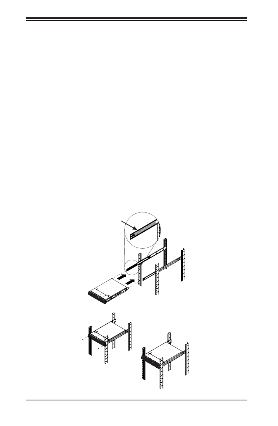
Figure 2-6. Installing into a Rack
Ball-Bearing
Shuttle
Standard Chassis Installation
Installing the Chassis into a Rack (Figure 2-6)
1. Conrm that the inner rails are properly installed on the chassis.
2. Conrm that the outer rails are correctly installed on the rack.
3. Pull the middle rail out from the front of the outer rail and make sure that the
ball-bearing shuttle is at the front locking position of the middle rail.
4. Align the chassis inner rails with the front of the middle rails.
5. Slide the inner rails on the chassis into the middle rails, keeping the pressure
even on both sides, until the locking tab of the inner rail clicks into the front of
the middle rail, locking the chassis into the fully extended position.
6. Depress the locking tabs of both sides at the same time and push the chassis
all the way into the rear of the rack.
7. If necessary for security purposes, use screws to secure the chassis handles
to the front of the rack.
Note: The gure below is for illustrative purposes only. Always install servers to
the bottom of the rack rst.

Chapter 3: System Interface
3-1
Chapter 3
System Interface
3-1 Overview
There are several LEDs on the control panel and on the drive carriers to keep you
constantly informed of the overall status of the system. SC217HQ+ models include
four front panels on the handles of the chassis which control each of the systems.
This chapter explains the meanings of all LED indicators and the appropriate
response you may need to take.
Figure 3-1. Control Panel

SUPERSERVER 2028TP-HC0R/HC0TR/HC0FR USER'S MANUAL
3-2
3-2 Control Panel Button
Alert
This LED is illuminated when an alert condition occurs.
• A solid red light indicates an overheat condition in the system.
• A ashing red light which ashes in one second intervals indicates a fan failure.
Power
The main power button on each of the four control panels is used to apply or remove
power from the power supply to each of the four systems in the chassis. Turning
power to the system off with this button removes the main power, but keeps standby
power supplied to the system. Therefore, you must unplug the AC power cord from
any external power source before servicing. The power button has a built-in LED
which will turn green when the power is on.
UID
When used with a UID compatible motherboard, the UID button is used to turn on
or off the blue light function of the LED. This is built into the front side of the UID
button and at the rear end of each motherboard node, for those motherboards which
support it. Once the blue light is activated, the unit can be easily located in very
large racks and server banks.
3-3 Control Panel LEDs
The four control panels are located on the front handle of the SC217HQ+ chassis.
Each control panel has two additional LEDs. These LEDs provide you with critical
information related to different parts of the system. This section explains what each
LED indicates when illuminated and any corrective action you may need to take.
!

Chapter 3: System Interface
3-3
• A ashing red light which ashes in four second intervals indicates a power
failure.
When notied of an alert, check the routing of the cables and make sure all fans
are present and operating normally. You should also check to make sure that the
chassis covers and air shrouds are installed. Finally, verify that the heatsinks are
installed properly. This LED will remain ashing or on as long as the temperature
is too high or a fan does not function properly.
NIC
Indicates network activity on either LAN1 or LAN2 when ashing.
3-4 Hard Drive Carrier LEDs
Hard Drives
Each drive carrier has two LEDs.
• Blue: When illuminated, this blue LED (on the front of the drive carrier) indicates
drive activity. A connection to the backplane enables this LED to blink on and
off when that particular drive is being accessed.
• Red: The red LED to indicate a hard drive failure. If one of the hard drives fail,
you should be notied by your system management software.

SUPERSERVER 2028TP-HC0R/HC0TR/HC0FR USER'S MANUAL
3-4
Notes

4-1
Chapter 4: Warning Statements for AC Systems
Chapter 4
Standardized Warning Statements for AC Systems
4-1 About Standardized Warning Statements
The following statements are industry standard warnings, provided to warn the user
of situations which have the potential for bodily injury. Should you have questions
or experience difficulty, contact Supermicro's Technical Support department
for assistance. Only certied technicians should attempt to install or congure
components.
Read this appendix in its entirety before installing or conguring components in the
Supermicro chassis.
These warnings may also be found on our web site at http://www.supermicro.com/
about/policies/safety_information.cfm.
Warning!
This warning symbol means danger. You are in a situation that could cause bodily
injury. Before you work on any equipment, be aware of the hazards involved with
electrical circuitry and be familiar with standard practices for preventing accidents.
Warning Denition
警告の定義
この警告サインは危険を意味します。
人身事故につながる可能性がありますので、いずれの機器でも動作させる前に、
電気回路に含まれる危険性に注意して、標準的な事故防止策に精通して下さい。
此警告符号代表危险。
您正处于可能受到严重伤害的工作环境中。在您使用设备开始工作之前,必须充分意
识到触电的危险,并熟练掌握防止事故发生的标准工作程序。请根据每项警告结尾的
声明号码找到此设备的安全性警告说明的翻译文本。
此警告符號代表危險。
您目前所處的工作環境可能讓您受傷。您使用任何設備之前,請注意觸電的危險,
並且要熟悉預防事故發生的標準工作程序。請依照每一注意事項後的號碼找到相關
的翻譯說明內容。

4-2
SUPERSERVER 2028TP-HC0R/HC0TR/HC0FR USER'S MANUAL
Warnung
WICHTIGE SICHERHEITSHINWEISE
Dieses Warnsymbol bedeutet Gefahr. Sie benden sich in einer Situation, die zu
Verletzungen führen kann. Machen Sie sich vor der Arbeit mit Geräten mit den
Gefahren elektrischer Schaltungen und den üblichen Verfahren zur Vorbeugung
vor Unfällen vertraut. Suchen Sie mit der am Ende jeder Warnung angegebenen
Anweisungsnummer nach der jeweiligen Übersetzung in den übersetzten
Sicherheitshinweisen, die zusammen mit diesem Gerät ausgeliefert wurden.
BEWAHREN SIE DIESE HINWEISE GUT AUF.
INSTRUCCIONES IMPORTANTES DE SEGURIDAD
Este símbolo de aviso indica peligro. Existe riesgo para su integridad física. Antes
de manipular cualquier equipo, considere los riesgos de la corriente eléctrica y
familiarícese con los procedimientos estándar de prevención de accidentes. Al
nal de cada advertencia encontrará el número que le ayudará a encontrar el texto
traducido en el apartado de traducciones que acompaña a este dispositivo.
GUARDE ESTAS INSTRUCCIONES.
IMPORTANTES INFORMATIONS DE SÉCURITÉ
Ce symbole d'avertissement indique un danger. Vous vous trouvez dans une
situation pouvant entraîner des blessures ou des dommages corporels. Avant
de travailler sur un équipement, soyez conscient des dangers liés aux circuits
électriques et familiarisez-vous avec les procédures couramment utilisées pour
éviter les accidents. Pour prendre connaissance des traductions des avertissements
gurant dans les consignes de sécurité traduites qui accompagnent cet appareil,
référez-vous au numéro de l'instruction situé à la n de chaque avertissement.
CONSERVEZ CES INFORMATIONS.
הרהזא תורהצה ןונקת
הלבח ינפמ שמתשמה תא ריהזהל תנמ לע ,היישעתה ינקת יפ לע תורהזא ןה תואבה תורהצה
הכימת תקלחמ םע רשק רוציל שי ,יהשלכ היעבב תולקתיה וא תולאש שיו הדימב .תירשפא תיזיפ
.םיביכרה תא רידגהל וא ןיקתהל םיאשר דבלב םיכמסומ םיאנכט .ורקימרפוס לש תינכט
.ורקימרפוס יזראמב םיביכרה תרדגה וא תנקתה ינפל ואולמב חפסנה תא אורקל שי

4-3
Chapter 4: Warning Statements for AC Systems
안전을 위한 주의사항
경고!
이 경고 기호는 위험이 있음을 알려 줍니다. 작업자의 신체에 부상을 야기 할 수
있는 상태에 있게 됩니다. 모든 장비에 대한 작업을 수행하기 전에 전기회로와
관련된 위험요소들을 확인하시고 사전에 사고를 방지할 수 있도록 표준
작업절차를 준수해 주시기 바랍니다.
해당 번역문을 찾기 위해 각 경고의 마지막 부분에 제공된 경고문 번호를
참조하십시오
BELANGRIJKE VEILIGHEIDSINSTRUCTIES
Dit waarschuwings symbool betekent gevaar. U verkeert in een situatie die
lichamelijk letsel kan veroorzaken. Voordat u aan enige apparatuur gaat werken,
dient u zich bewust te zijn van de bij een elektrische installatie betrokken risico's
en dient u op de hoogte te zijn van de standaard procedures om ongelukken te
voorkomen. Gebruik de nummers aan het eind van elke waarschuwing om deze te
herleiden naar de desbetreffende locatie.
BEWAAR DEZE INSTRUCTIES
. !

4-4
SUPERSERVER 2028TP-HC0R/HC0TR/HC0FR USER'S MANUAL
Installation Instructions
Warning!
Read the installation instructions before connecting the system to the power source.
Warnung
Vor dem Anschließen des Systems an die Stromquelle die Installationsanweisungen
lesen.
¡Advertencia!
Lea las instrucciones de instalación antes de conectar el sistema a la red de
alimentación.
Attention
Avant de brancher le système sur la source d'alimentation, consulter les directives
d'installation.
設置手順書
システムを電源に接続する前に、設置手順書をお読み下さい。
시스템을 전원에 연결하기 전에 설치 안내를 읽어주십시오.
Waarschuwing
Raadpleeg de installatie-instructies voordat u het systeem op de voedingsbron
aansluit.
警告
将此系统连接电源前,请先阅读安装说明。
警告
將系統與電源連接前,請先閱讀安裝說明。
.חתמ רוקמל תכרעמה רוביח ינפל הנקתה תוארוה תא אורקל שי

4-5
Chapter 4: Warning Statements for AC Systems
Circuit Breaker
Warning!
This product relies on the building's installation for short-circuit (overcurrent)
protection. Ensure that the protective device is rated not greater than: 250 V, 20 A.
サーキット・ブレーカー
この製品は、短絡(過電流)保護装置がある建物での設置を前提としています。
保護装置の定格が250 V、20 Aを超えないことを確認下さい。
Warnung
Dieses Produkt ist darauf angewiesen, dass im Gebäude ein Kurzschluss-
bzw. Überstromschutz installiert ist. Stellen Sie sicher, dass der Nennwert der
Schutzvorrichtung nicht mehr als: 250 V, 20 A beträgt.
¡Advertencia!
Este equipo utiliza el sistema de protección contra cortocircuitos (o sobrecorrientes)
del edicio. Asegúrese de que el dispositivo de protección no sea superior a: 250
V, 20 A.
Attention
Pour ce qui est de la protection contre les courts-circuits (surtension), ce produit
dépend de l'installation électrique du local. Vériez que le courant nominal du
dispositif de protection n'est pas supérieur à :250 V, 20 A.
警告
此产品的短路(过载电流)保护由建筑物的供电系统提供,确保短路保护设备的额定电
流不大于250V,20A。
警告
此產品的短路(過載電流)保護由建築物的供電系統提供,確保短路保護設備的額定電
流不大於250V,20A。
יכ אדוול שי .ילמשח רצק תעינמל םינבמב תנקתומה הנגה לע ךמתסמ
250VDC, 20A-מ רתוי אל אוה ילמשחה רצקה ינפמ ןגמה רישכמ
4-6
SUPERSERVER 2028TP-HC0R/HC0TR/HC0FR USER'S MANUAL
Power Disconnection Warning
電源切断の警告
システムコンポーネントの取り付けまたは取り外しのために、シャーシー内部にアクセス
するには、
システムの電源はすべてのソースから切断され、電源コードは電源モジュールから取り
外す必要があります。
警告
在你打开机箱并安装或移除内部器件前,必须将系统完全断电,并移除电源线。
警告
在您打開機殼安裝或移除內部元件前,必須將系統完全斷電,並移除電源線。
Warnung
Das System muss von allen Quellen der Energie und vom Netzanschlusskabel
getrennt sein, das von den Spg.Versorgungsteilmodulen entfernt wird, bevor es
auf den Chassisinnenraum zurückgreift, um Systemsbestandteile anzubringen oder
zu entfernen.
Warning!
The system must be disconnected from all sources of power and the power cord
removed from the power supply module(s) before accessing the chassis interior to
install or remove system components.
!
()
. 250V(), 20A()
.
Waarschuwing
Dit product is afhankelijk van de kortsluitbeveiliging (overspanning) van
uw electrische installatie. Controleer of het beveiligde aparaat niet groter
gedimensioneerd is dan 250V, 20A.
20A, 250V :

4-7
Chapter 4: Warning Statements for AC Systems
¡Advertencia!
El sistema debe ser disconnected de todas las fuentes de energía y del cable
eléctrico quitado de los módulos de fuente de alimentación antes de tener acceso
el interior del chasis para instalar o para quitar componentes de sistema.
Attention
Le système doit être débranché de toutes les sources de puissance ainsi que de
son cordon d'alimentation secteur avant d'accéder à l'intérieur du chassis pour
installer ou enlever des composants de systéme.
경고!
시스템에 부품들을 장착하거나 제거하기 위해서는 섀시 내부에 접근하기 전에
반드시 전원 공급장치로부터 연결되어있는 모든 전원과 전기코드를 분리해주어야
합니다.
Waarschuwing
Voordat u toegang neemt tot het binnenwerk van de behuizing voor het installeren
of verwijderen van systeem onderdelen, dient u alle spanningsbronnen en alle
stroomkabels aangesloten op de voeding(en) van de behuizing te verwijderen
ילמשח קותינ ינפמ הרהזא
הרהזא!
קפסהמ ילמשחה לבכ תא ריסהל שיו למשחה תורוקמ לכמ תכרעמה תא קתנל שי
םיביכר תרסה וא תנקתה ךרוצל זראמה לש ימינפה קלחל השיג ינפל.

4-8
SUPERSERVER 2028TP-HC0R/HC0TR/HC0FR USER'S MANUAL
Equipment Installation
機器の設置
トレーニングを受け認定された人だけがこの装置の設置、交換、またはサービスを許可
されています。
Warning!
Only trained and qualied personnel should be allowed to install, replace, or service
this equipment.
Warnung
Das Installieren, Ersetzen oder Bedienen dieser Ausrüstung sollte nur geschultem,
qualiziertem Personal gestattet werden.
¡Advertencia!
Solamente el personal calicado debe instalar, reemplazar o utilizar este equipo.
Attention
Il est vivement recommandé de confier l'installation, le remplacement et la
maintenance de ces équipements à des personnels qualiés et expérimentés.
경고!
훈련을 받고 공인된 기술자만이 이 장비의 설치, 교체 또는 서비스를 수행할 수
있습니다.
警告
只有经过培训且具有资格的人员才能进行此设备的安装、更换和维修。
警告
只有經過受訓且具資格人員才可安裝、更換與維修此設備。
!הרהזא
.דויצה רובע תוריש תתל וא דויצה תא ףילחהל ,ןיקתהל יאשר דבלב ךמסומ תווצ

4-9
Chapter 4: Warning Statements for AC Systems
アクセス制限区域
このユニットは、アクセス制限区域に設置されることを想定しています。
アクセス制限区域は、特別なツール、鍵と錠前、その他のセキュリティの手段を用いての
み出入りが可能です。
Warning!
This unit is intended for installation in restricted access areas. A restricted access
area can be accessed only through the use of a special tool, lock and key, or other
means of security. (This warning does not apply to workstations).
Restricted Area
Waarschuwing
Deze apparatuur mag alleen worden geïnstalleerd, vervangen of hersteld door
geschoold en gekwaliceerd personeel.
Warnung
Diese Einheit ist zur Installation in Bereichen mit beschränktem Zutritt vorgesehen.
Der Zutritt zu derartigen Bereichen ist nur mit einem Spezialwerkzeug, Schloss und
Schlüssel oder einer sonstigen Sicherheitsvorkehrung möglich.
¡Advertencia!
Esta unidad ha sido diseñada para instalación en áreas de acceso restringido.
Sólo puede obtenerse acceso a una de estas áreas mediante la utilización de una
herramienta especial, cerradura con llave u otro medio de seguridad.
Attention
Cet appareil doit être installée dans des zones d'accès réservés. L'accès à une
zone d'accès réservé n'est possible qu'en utilisant un outil spécial, un mécanisme
de verrouillage et une clé, ou tout autre moyen de sécurité.
警告
此部件应安装在限制进出的场所,限制进出的场所指只能通过使用特殊工具、锁和钥
匙或其它安全手段进出的场所。
警告
此裝置僅限安裝於進出管制區域,進出管制區域係指僅能以特殊工具、鎖頭及鑰匙或
其他安全方式才能進入的區域。

4-10
SUPERSERVER 2028TP-HC0R/HC0TR/HC0FR USER'S MANUAL
Battery Handling
Warning!
There is the danger of explosion if the battery is replaced incorrectly. Replace the
battery only with the same or equivalent type recommended by the manufacturer.
Dispose of used batteries according to the manufacturer's instructions
경고!
이 장치는 접근이 제한된 구역에 설치하도록 되어있습니다. 특수도구, 잠금 장치 및
키, 또는 기타 보안 수단을 통해서만 접근 제한 구역에 들어갈 수 있습니다.
Waarschuwing
Dit apparaat is bedoeld voor installatie in gebieden met een beperkte toegang.
Toegang tot dergelijke gebieden kunnen alleen verkregen worden door gebruik te
maken van speciaal gereedschap, slot en sleutel of andere veiligheidsmaatregelen.
電池の取り扱い
電池交換が正しく行われなかった場合、破裂の危険性があります。 交換する電池はメー
カーが推奨する型、または同等のものを使用下さい。 使用済電池は製造元の指示に従
って処分して下さい。
警告
电池更换不当会有爆炸危险。请只使用同类电池或制造商推荐的功能相当的电池更
换原有电池。请按制造商的说明处理废旧电池。
警告
電池更換不當會有爆炸危險。請使用製造商建議之相同或功能相當的電池更換原有
電池。請按照製造商的說明指示處理廢棄舊電池。
תלבגומ השיג םע רוזא
!הרהזא
תרזעב תנתינ השיגה .השיג תלבגה םהב שיש םירוזאב הדיחיה תא ןיקתה
(.דכו לוענמ ,חתפמ( דבלב החטבא ילכ'
.

4-11
Chapter 4: Warning Statements for AC Systems
Warnung
Bei Einsetzen einer falschen Batterie besteht Explosionsgefahr. Ersetzen Sie die
Batterie nur durch den gleichen oder vom Hersteller empfohlenen Batterietyp.
Entsorgen Sie die benutzten Batterien nach den Anweisungen des Herstellers.
Attention
Danger d'explosion si la pile n'est pas remplacée correctement. Ne la remplacer
que par une pile de type semblable ou équivalent, recommandée par le fabricant.
Jeter les piles usagées conformément aux instructions du fabricant.
¡Advertencia!
Existe peligro de explosión si la batería se reemplaza de manera incorrecta.
Reemplazar la batería exclusivamente con el mismo tipo o el equivalente
recomendado por el fabricante. Desechar las baterías gastadas según las
instrucciones del fabricante.
경고!
배터리가 올바르게 교체되지 않으면 폭발의 위험이 있습니다. 기존 배터리와
동일하거나 제조사에서 권장하는 동등한 종류의 배터리로만 교체해야 합니다.
제조사의 안내에 따라 사용된 배터리를 처리하여 주십시오.
Waarschuwing
Er is ontplofngsgevaar indien de batterij verkeerd vervangen wordt. Vervang de
batterij slechts met hetzelfde of een equivalent type die door de fabrikant aanbevolen
wordt. Gebruikte batterijen dienen overeenkomstig fabrieksvoorschriften afgevoerd
te worden.
!הרהזא
ףילחהל שי .הניקת אל ךרדב הפלחוהו הדימב הללוסה לש ץוציפ תנכס תמייק
.תצלמומ ןרצי תרבחמ םאותה גוסב הללוסה תא
.ןרציה תוארוה יפל עצבל שי תושמושמה תוללוסה קוליס

4-12
SUPERSERVER 2028TP-HC0R/HC0TR/HC0FR USER'S MANUAL
Warnung
Dieses Gerät kann mehr als eine Stromzufuhr haben. Um sicherzustellen, dass
der Einheit kein trom zugeführt wird, müssen alle Verbindungen entfernt werden.
¡Advertencia!
Puede que esta unidad tenga más de una conexión para fuentes de alimentación.
Para cortar por completo el suministro de energía, deben desconectarse todas las
conexiones.
Attention
Cette unité peut avoir plus d'une connexion d'alimentation. Pour supprimer toute
tension et tout courant électrique de l'unité, toutes les connexions d'alimentation
doivent être débranchées.
Redundant Power Supplies
Warning!
This unit might have more than one power supply connection. All connections must
be removed to de-energize the unit.
冗長電源装置
このユニットは複数の電源装置が接続されている場合があります。
ユニットの電源を切るためには、すべての接続を取り外さなければなりません。
警告
此部件连接的电源可能不止一个,必须将所有电源断开才能停止给该部件供电。
警告
此裝置連接的電源可能不只一個,必須切斷所有電源才能停止對該裝置的供電。
דחא קפסמ רתוי םייק םא
!הרהזא
ןקורל תנמ לע םירוביחה לכ תא ריסהל שי .קפס לש דחא רוביחמ רתוי שי הדחיל
.הדיחיה תא

4-13
Chapter 4: Warning Statements for AC Systems
Backplane Voltage
バックプレーンの電圧
システムの稼働中は危険な電圧または電力が、バックプレーン上にかかっています。
修理する際には注意ください。
警告
当系统正在进行时,背板上有很危险的电压或能量,进行维修时务必小心。
警告
當系統正在進行時,背板上有危險的電壓或能量,進行維修時務必小心。
Warnung
Wenn das System in Betrieb ist, treten auf der Rückwandplatine gefährliche
Spannungen oder Energien auf. Vorsicht bei der Wartung.
¡Advertencia!
Cuando el sistema está en funcionamiento, el voltaje del plano trasero es peligroso.
Tenga cuidado cuando lo revise.
Attention
Lorsque le système est en fonctionnement, des tensions électriques circulent sur
le fond de panier. Prendre des précautions lors de la maintenance.
Warning!
Hazardous voltage or energy is present on the backplane when the system is
operating. Use caution when servicing.
!
.
.
Waarschuwing
Deze eenheid kan meer dan één stroomtoevoeraansluiting bevatten. Alle
aansluitingen dienen verwijderd te worden om het apparaat stroomloos te maken.
.
4-14
SUPERSERVER 2028TP-HC0R/HC0TR/HC0FR USER'S MANUAL
Comply with Local and National Electrical Codes
Warning!
Installation of the equipment must comply with local and national electrical codes.
地方および国の電気規格に準拠
機器の取り付けはその地方および国の電気規格に準拠する必要があります。
Warnung
Die Installation der Geräte muss den Sicherheitsstandards entsprechen.
¡Advertencia!
La instalacion del equipo debe cumplir con las normas de electricidad locales y
nacionales.
!
(Backplane)
. .
Waarschuwing
Een gevaarlijke spanning of energie is aanwezig op de backplane wanneer het
systeem in gebruik is. Voorzichtigheid is geboden tijdens het onderhoud.
警告
设备安装必须符合本地与本国电气法规。
警告
設備安裝必須符合本地與本國電氣法規。
ירוחאה לנפב חתמ
!הרהזא
ךלהמב רהזיהל שי .תכרעמה לועפת ןמזב ירוחאה לנפב חתמ תנכס
.הדובעה
4-15
Chapter 4: Warning Statements for AC Systems
Product Disposal
Warning!
Ultimate disposal of this product should be handled according to all national laws
and regulations.
Attention
L'équipement doit être installé conformément aux normes électriques nationales
et locales.
!
.
Waarschuwing
Bij installatie van de apparatuur moet worden voldaan aan de lokale en nationale
elektriciteitsvoorschriften.
製品の廃棄
この製品を廃棄処分する場合、国の関係する全ての法律・条例に従い処理する必要が
あります。
警告
本产品的废弃处理应根据所有国家的法律和规章进行。
警告
本產品的廢棄處理應根據所有國家的法律和規章進行。
Warnung
Die Entsorgung dieses Produkts sollte gemäß allen Bestimmungen und Gesetzen
des Landes erfolgen.
¡Advertencia!
Al deshacerse por completo de este producto debe seguir todas las leyes y
reglamentos nacionales.
יצראה למשחה יקוח םואית
!הרהזא
.םייצראהו םיימוקמה למשחה יקוחל תמאות תויהל תבייח דויצה ת
4-16
SUPERSERVER 2028TP-HC0R/HC0TR/HC0FR USER'S MANUAL
Waarschuwing
De uiteindelijke verwijdering van dit product dient te geschieden in overeenstemming
met alle nationale wetten en reglementen.
ファン・ホットスワップの警告
警告!回転部品に注意。運転中は回転部(羽根)に触れないでください。 シャーシから冷
却ファン装置を取り外した際、ファンがまだ回転している可能性があります。 ファンの開
口部に、指、ドライバー、およびその他のものを近づけないで下さい。
警告!
警告!危险的可移动性零件。请务必与转动的风扇叶片保持距离。 当您从机架移除
风扇装置,风扇可能仍在转动。小心不要将手指、螺丝起子和其他物品太靠近风扇
警告
危險的可移動性零件。請務必與轉動的風扇葉片保持距離。 當您從機架移除風扇裝
置,風扇可能仍在轉動。小心不要將手指、螺絲起子和其他物品太靠近風扇。
경고!
이 제품은 해당 국가의 관련 법규 및 규정에 따라 폐기되어야 합니다.
Hot Swap Fan Warning
Warning!
Hazardous moving parts. Keep away from moving fan blades. The fans might still
be turning when you remove the fan assembly from the chassis. Keep ngers,
screwdrivers, and other objects away from the openings in the fan assembly's
housing.
Attention
La mise au rebut ou le recyclage de ce produit sont généralement soumis à des
lois et/ou directives de respect de l'environnement. Renseignez-vous auprès de
l'organisme compétent.
רצומה קוליס
!הרהזא
.הנידמה יקוחו תויחנהל םאתהב תויהל בייח הז רצומ לש יפוס קוליס

4-17
Chapter 4: Warning Statements for AC Systems
Warnung
Gefährlich Bewegende Teile. Von den bewegenden Lüfterblätter fern halten.
Die Lüfter drehen sich u. U. noch, wenn die Lüfterbaugruppe aus dem Chassis
genommen wird. Halten Sie Finger, Schraubendreher und andere Gegenstände
von den Öffnungen des Lüftergehäuses entfernt.
¡Advertencia!
Riesgo de piezas móviles. Mantener alejado de las aspas del ventilador. Los
ventiladores podran dar vuelta cuando usted quite ell montaje del ventilador del
chasis. Mandtenga los dedos, los destornilladores y todos los objetos lejos de las
aberturas del ventilador
Attention
Pieces mobiles dangereuses. Se tenir a l’ecart des lames du ventilateur Il est
possible que les ventilateurs soient toujours en rotation lorsque vous retirerez le
bloc ventilateur du châssis. Prenez garde à ce que doigts, tournevis et autres objets
soient éloignés du logement du bloc ventilateur.
경고!
움직이는 위험한 부품. 회전하는 송풍 날개에 접근하지 마세요. 섀시로부터 팬
조립품을 제거할 때 팬은 여전히 회전하고 있을 수 있습니다. 팬 조림품 외관의
열려있는 부분들로부터 손가락 및 스크류드라이버, 다른 물체들이 가까이 하지
않도록 배치해 주십시오.
Waarschuwing
Gevaarlijk bewegende onderdelen. Houd voldoende afstand tot de bewegende
ventilatorbladen. Het is mogelijk dat de ventilator nog draait tijdens het verwijderen
van het ventilatorsamenstel uit het chassis. Houd uw vingers, schroevendraaiers en
eventuele andere voorwerpen uit de buurt van de openingen in de ventilatorbehuizing.
!הרהזא
יקלח תא םיריסמ רשאכהלועפב ררוואמה יבהלמ קחרתה .םינכוסמ םיענ םיקלח
תא חוטב קחרמל קיחרהל שי .םידבוע ןיידע םיררוואמהו ןכתי ,זראמהמ ררוואמה
ררוואמה ךותב םיחתפהמ םינוש הדובע ילכו תועבצאה
. . !
.

4-18
SUPERSERVER 2028TP-HC0R/HC0TR/HC0FR USER'S MANUAL
Warning!
Warning! When installing the product, use the provided or designated connection
cables, power cables and AC. Using any other cables and adaptors could cause
a malfunction or a re. Electrical Appliance and Material Safety Law prohibits the
use of UL or CSA -certied cables (that have UL/CSA shown on the code) for any
other electrical devices than products designated by Supermicro only..
Power Cable and AC Adapter
Warnung
Nutzen Sie beim Installieren des Produkts ausschließlich die von uns zur Verfügung
gestellten Verbindungskabeln, Stromkabeln und/oder Adapater, die Ihre örtlichen
Sicherheitsstandards einhalten. Der Gebrauch von anderen Kabeln und Adapter
können Fehlfunktionen oder Feuer verursachen. Die Richtlinien untersagen das
Nutzen von UL oder CAS zertizierten Kabeln (mit UL/CSA gekennzeichnet), an
Geräten oder Produkten die nicht mit Supermicro gekennzeichnet sind.
電源コードとACアダプター
製品を設置する場合、提供または指定および購入された接続ケーブル、電源コードとAC
アダプターを 該当する地域の条例や安全基準に適合するコードサイズやプラグと共に
使用下さい。 他のケーブルやアダプタを使用すると故障や火災の原因になることがあり
ます。 電気用品安全法は、ULまたはCSA認定のケーブル(UL/CSEマークがコードに表記)
を Supermicroが指定する製品以外に使用することを禁止しています。
警告
安装此产品时,请使用本身提供的或指定的或采购的连接线,电源线和电源适配器,包
含遵照当地法规和安全要求的合规的电源线尺寸和插头.使用其它线材或适配器可能
会引起故障或火灾。除了Supermicro所指定的产品,电气用品和材料安全法律规定禁
止 使用未经UL或CSA认证的线材。(线材上会显示UL/CSA符号)。
警告
安裝此產品時,請使用本身提供的或指定的或採購的連接線,電源線和電源適配器,包
含遵照當地法規和安全要求的合規的電源線尺寸和插頭.使用其它線材或適配器可能
會引起故障或火災。除了Supermicro所指定的產品,電氣用品和材料安全法律規定禁
止 使用未經UL或CSA認證的線材。 (線材上會顯示UL/CSA符號)。

4-19
Chapter 4: Warning Statements for AC Systems
¡Advertencia!
Cuando instale el producto, utilice la conexión provista o designada o procure
cables, Cables de alimentación y adaptadores de CA que cumplan con los códigos
locales y los requisitos de seguridad, incluyendo el tamaño adecuado del cable y el
enchufe. El uso de otros cables y adaptadores podría causar un mal funcionamiento
o un incendio. La Ley de Seguridad de Aparatos Eléctricos y de Materiales prohíbe
El uso de cables certicados por UL o CSA (que tienen el certicado UL / CSA en
el código) para cualquier otros dispositivos eléctricos que los productos designados
únicamente por Supermicro.Attention
Attention
Lors de l'installation du produit, utilisez les cables de connection fournis ou désigné
ou achetez des cables, cables de puissance et adaptateurs respectant les normes
locales et les conditions de securite y compris les tailles de cables et les prises
electriques appropries. L'utilisation d'autres cables et adaptateurs peut provoquer
un dysfonctionnement ou un incendie. Appareils électroménagers et la Loi sur la
Sécurité Matériel interdit l'utilisation de câbles certies- UL ou CSA (qui ont UL ou
CSA indiqué sur le code) pour tous les autres appareils électriques sauf les produits
désignés par Supermicro seulement.
ימאתמו םיילמשח םילבכ AC
הרהזא!
םימאתמו םיקפס ,םילבכב שמתשהל שי ,רצומה תא םיניקתמ רשאכ AC וא ושכרנ רשא
הנוכנ הדימ ללוכ ,תוימוקמה תוחיטבה תושירדל ומאתוה רשאו ,הנקתהה ךרוצל ומאתוה
רצק וא הלקתל םורגל לולע ,רחא גוסמ םאתמ וא לבכ לכב שומיש . עקתהו לבכה לש
שמתשהל רוסיא םייק ,תוחיטבה יקוחו למשחה ירישכמב שומישה יקוחל םאתהב .ילמשח
ב םיכמסומה םילבכב- UL ב וא-CSA (לש דוק םהילע עיפומ רשאכ (UL/CSA רובע
י"ע םאתוה רשא רצומב קר אלא ,רחא ילמשח רצומ לכ Supermicro דבלב.
.
.
UL CSA (UL/CSA)
Supermicro.

4-20
SUPERSERVER 2028TP-HC0R/HC0TR/HC0FR USER'S MANUAL
전원 케이블 및 AC 어댑터
경고! 제품을 설치할 때 현지 코드 및 적절한 굵기의 코드와 플러그를 포함한 안전
요구 사항을 준수하여 제공되거나 지정된 연결 혹은 구매 케이블, 전원 케이블 및
AC 어댑터를 사용하십시오.
다른 케이블이나 어댑터를 사용하면 오작동이나 화재가 발생할 수 있습니다. 전기
용품 안전법은 UL 또는 CSA 인증 케이블 (코드에 UL / CSA가 표시된 케이블)
을 Supermicro가 지정한 제품 이외의 전기 장치에 사용하는 것을 금지합니다.
Stroomkabel en AC-Adapter
Waarschuwing! Bij het aansluiten van het Product uitsluitend gebruik maken van de
geleverde Kabels of een andere geschikte aan te schaffen Aansluitmethode, deze
moet altijd voldoen aan de lokale voorschriften en veiligheidsnormen, inclusief de
juiste kabeldikte en stekker. Het gebruik van niet geschikte Kabels en/of Adapters
kan een storing of brand veroorzaken. Wetgeving voor Elektrische apparatuur en
Materiaalveiligheid verbied het gebruik van UL of CSA -gecerticeerde Kabels (met
UL/CSA in de code) voor elke andere toepassing dan de door Supermicro hiervoor
beoogde Producten.

Chapter 5: Advanced Serverboard Setup
5-1
Chapter 5
Advanced Serverboard Setup
This chapter covers the steps required to install the X10DRT-P/PT/PIBF serverboard
into the chassis, connect the data and power cables and install add-on cards.
All serverboard jumpers and connections are also described. A layout and quick
reference chart are included in this chapter for your reference. Remember to
completely close the chassis when you have nished working with the serverboard
to better cool and protect the system.
5-1 Handling the Serverboard
Electrostatic Discharge (ESD) can damage electronic com ponents. To prevent
damage to any printed circuit boards (PCBs), it is important to handle them very
carefully (see previous chapter). To prevent the serverboard from bending, keep
one hand under the center of the board to support it when handling. The following
measures are generally sufcient to protect your equipment from electric static
discharge.
Precautions
• Use a grounded wrist strap designed to prevent Electrostatic Discharge (ESD).
• Touch a grounded metal object before removing any board from its antistatic bag.
• Handle a board by its edges only; do not touch its components, peripheral chips,
memory modules or gold contacts.
• When handling chips or modules, avoid touching their pins.
• Put the serverboard, add-on cards and peripherals back into their antistatic
bags when not in use.
• For grounding purposes, make sure your computer chassis provides excellent
conductivity between the power supply, the case, the mounting fasteners and
the serverboard.
Unpacking
The serverboard is shipped in antistatic packaging to avoid electrical static
discharge. When unpacking the board, make sure the person handling it is static
protected.

5-2
SUPERSERVER 2028TP-HC0R/HC0TR/HC0FR USER'S MANUAL
5-2 Connecting Cables
Now that the processors are installed, the next step is to connect the cables to
the serverboard.
Connecting Data Cables
The cables used to transfer data from the peripheral devices have been carefully
routed in precongured systems to prevent them from blocking the ow of cooling
air that moves through the system from front to back.
If you need to disconnect any of these cables, you should take care to reroute them
as they were originally after reconnecting them (make sure the red wires connect
to the pin 1 locations). If you are conguring the system, keep the airow in mind
when routing the cables.

Chapter 5: Advanced Serverboard Setup
5-3
5-3 Rear I/O Ports
See Figure 5-1 below for the and locations of the various rear I/O ports and the
UID switch.
Figure 5-1. Rear I/O Ports
Rear I/O Port Locations and Denitions
1. Dedicated IPMI LAN
2. Back Panel USB 3.0 Port 1
3. Back Panel USB 3.0 Port 0
4. Gigabit LAN 2
5. Gigabit LAN 1
6 QSFP (Quad Small Form-factor Pluggable) Connector for
Connect-X3 InniBand Port (X10DRT-PIBF only)
7. VGA Port
8 UID Switch
2
1
5
3
4
76 8

5-4
SUPERSERVER 2028TP-HC0R/HC0TR/HC0FR USER'S MANUAL
5-4 Processor and Heatsink Installation
Notes:
• Always remove the power cord before adding, removing or changing a CPU.
• When receiving a serverboard without a processor pre-installed, make sure that
the plastic CPU socket cap is in place and none of the socket pins are bent;
otherwise, contact your retailer immediately.
• If you buy a CPU separately, use only an Intel-certied, multi-directional heatsink.
• Avoid placing direct pressure to the top of the processor package.
• Install the processor into the CPU socket before installing the heatsink.
• Refer to the Supermicro web site for updates on CPU support.
Release
the lever labeled "Open 1st"
Installing a CPU
1. There are two levers on the LGA
2011 socket. First press and release
the load lever labeled "Open 1st".
OPEN 1st
OPEN 1st
Release
the lever labeled "Close 1st"
2. Press the second load lever labeled
"Close 1st" to release the load plate
from its locked position.

Chapter 5: Advanced Serverboard Setup
5-5
3. With the second lever fully
retracted, gently push down on
the "Open 1st" lever to loosen
the load plate. Lift the load
plate with your ngers to open it
completely.
4. Pop the plastic cap marked
"Warning" out of the load plate.
5. Holding the CPU carefully above
the socket, orient the CPU so
that all keys and edges will t
the socket.
OPEN 1st
IMPORTANT!
Caution: You can only install the CPU into the socket in one direction. Make sure
that the CPU is properly inserted into the socket before closing the load plate. If it
does not close properly, do not force it as it may damage your CPU. Instead, open
the load plate again and double-check that the CPU is aligned properly.
6. Carefully lower the CPU straight
down into the socket. Do not
move the CPU horizontally, and
do not rub the pins of the socket.
This may damage the CPU or
the socket.
Open the
load plate.
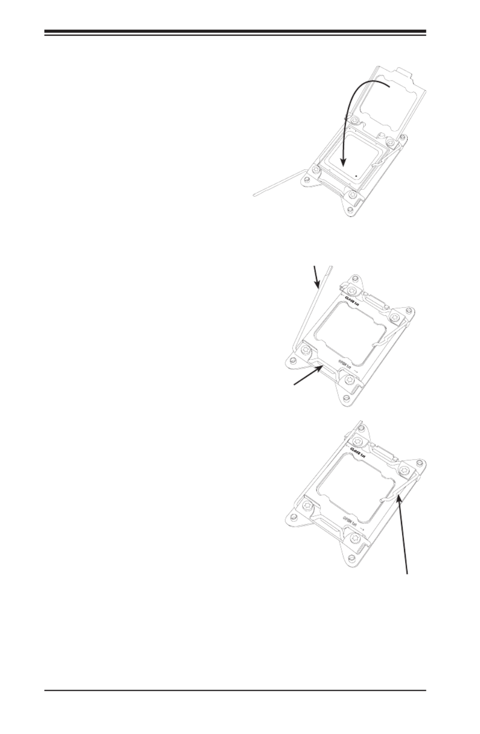
5-6
SUPERSERVER 2028TP-HC0R/HC0TR/HC0FR USER'S MANUAL
8. Make sure the locking mechanism
on the "Close 1st" lever catches
the lip of the load plate. Close and
lock the "Close 1st" lever.
Push down and lock
the
lever labeled "Open 1st"
OPEN 1st
OPEN 1st
Push down and lock the
lever labeled "Close 1st".
9. Close and lock the "Open 1st"
lever.
Engage the lip of
the load plate and
locking portion of
the lever."
7. With the "Close 1st" lever fully
retracted, gently close the load
plate.
Gently close
the load plate.
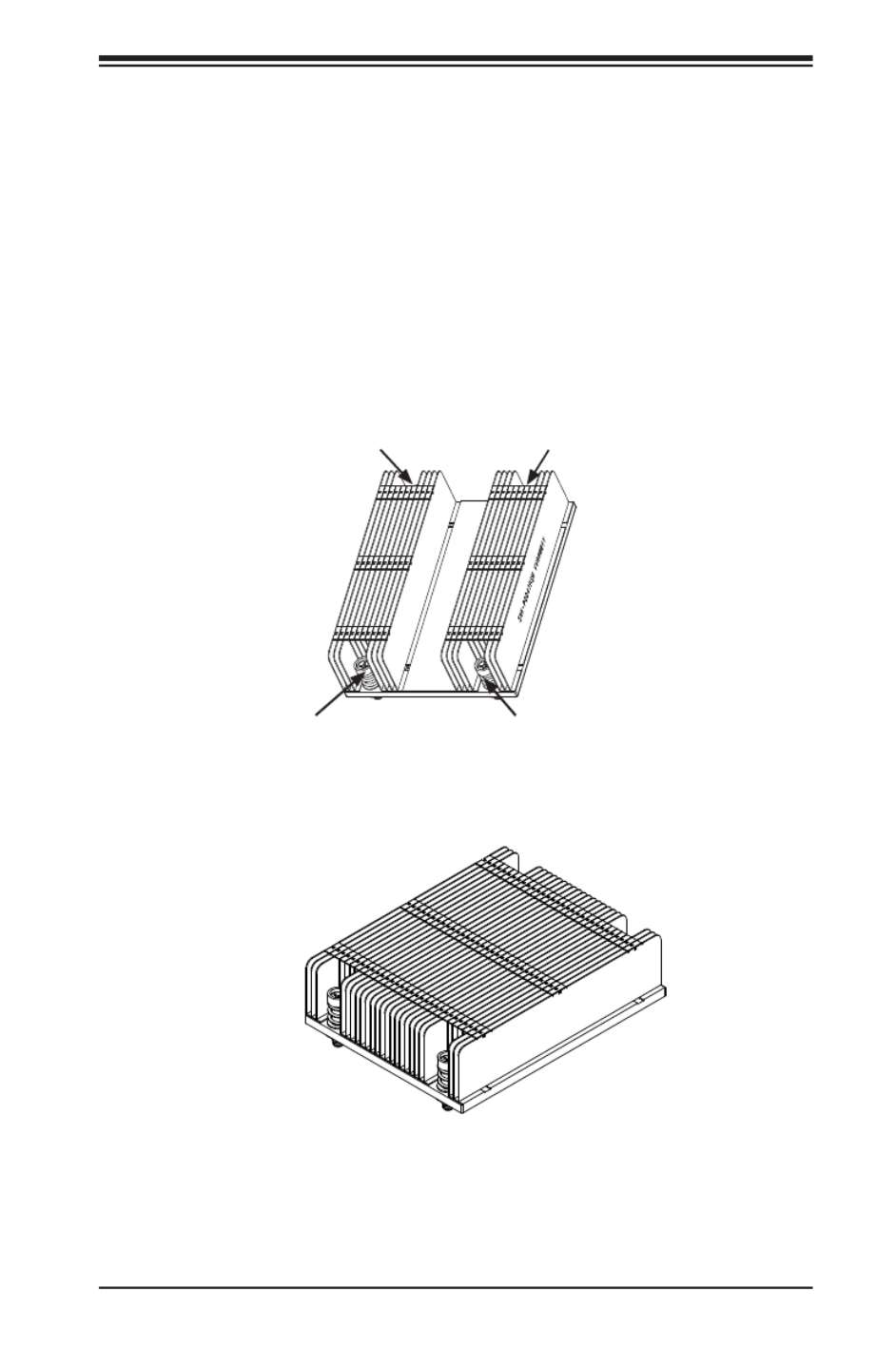
Chapter 5: Advanced Serverboard Setup
5-7
Installing a Passive CPU Heatsink
1. Do not apply any thermal grease to the heatsink or the CPU die -- the
required amount has already been applied.
2. Place the heatsink on top of the CPU so that the four mounting holes are
aligned with those on the Serverboard's and the Heatsink Bracket underneath.
3. Screw in two diagonal screws (i.e., the #1 and the #2 screws) until just snug
(-do not over-tighten the screws to avoid possible damage to the CPU.)
4. Finish the installation by fully tightening all four screws.
SNK-P0057PS
Screw#1
Screw#2
Screw#3
Screw#4
SNK-P0047PSM
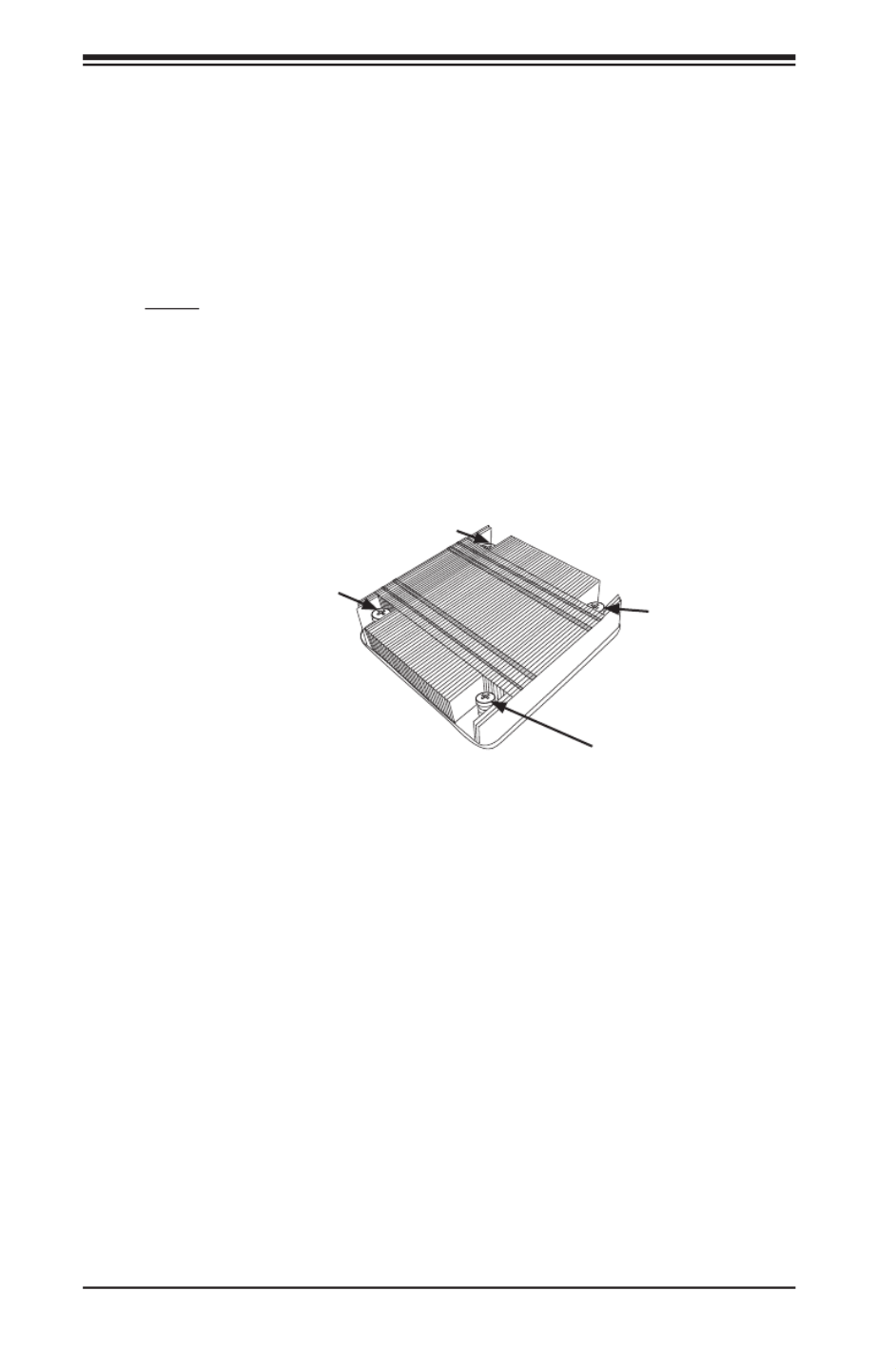
5-8
SUPERSERVER 2028TP-HC0R/HC0TR/HC0FR USER'S MANUAL
Removing the Heatsink
Caution: We DO NOT recommend that the CPU or the heatsink be removed. However,
if you do need to uninstall the heatsink, please follow the instructions below to prevent
damage to the CPU or the CPU socket.
1. Unscrew the heatsink screws from the serverboard in the sequence as shown
in the illustration below.
2. Gently wriggle the heatsink to loosen it from the CPU. (Do not use excessive
force when wriggling the heatsink!)
3. Once the heatsink is loosened, remove the heatsink from the CPU socket.
4. Remove the used thermal grease and clean the surface of the CPU and the
heatsink, Reapply the proper amount of thermal grease on the surface before
reinstalling the heatsink.
Loosen screws
in sequence as
shown.
Screw#2
Screw#1
Screw#3
Screw#4

Chapter 5: Advanced Serverboard Setup
5-9
5-5 Installing Memory
Installing Memory
1. Insert each memory module vertically into its slot, paying attention to the
notch along the bottom of the module to prevent inserting the module
incorrectly (see Figure 5-2).
2. Install starting with slot P1/DIMMA1.
3. Gently press down on the memory module until it snaps into place.
4. With two CPUs installed, repeat step 2 to populate the CPU2 DIMM slots.
5. See the tables that follow for details on populating the DIMM slots.
Note: It is highly recommended that you remove the power cord from the system
before installing or changing memory modules. Please refer to our web site for
memory that has been tested on the X10DRT-P/PT/PIBF serverboard. For best
performance, use memory modules of the same type and speed in the same bank.
Memory Support
The X10DRT-P/PT/PIBF has sixteen DIMM slots supporting up to 1024 GB
of LRDIMM (Load Reduced DIMM) or 512 GB of RDIMM (Registered DIMM)
DDR4-2133/1866/1600 MHz registered ECC memory.
Note: Check the Supermicro website (www.supermicro.com) for the latest memory
support information.
Socket Key
Release Tab
Release Tab
Figure 5-2. DIMM Installation
5-10
SUPERSERVER 2028TP-HC0R/HC0TR/HC0FR USER'S MANUAL
Processor & Memory Module Population Conguration
For the memory to work properly, follow the tables below when populating the
DIMM slots.
Processors and their Corresponding Memory Modules
CPU# Corresponding DIMMs
CPU 1 P1-
DIMMA1
P1-
DIMMB1
P1-
DIMMC1
P1-
DIMMD1
P1-
DIMMA2
P1-
DIMMB2
P1-
DIMMC2
P1-
DIMMD2
CPU2 P2-
DIMME1
P2-
DIMMF1
P2-
DIMMG1
P2-
DIMMH1
P2-
DIMME2
P2-
DIMM F2
P2-
DIMMG2
P2-
DIMMH2
Processor and Memory Module Population for Optimal Performance
Number of
CPUs+DIMMs CPU and Memory Population Conguration Table
1 CPU &
2 DIMMs
CPU1
P1-DIMMA1/P1-DIMMB1
1 CPU &
4 DIMMs
CPU1
P1-DIMMA1/P1-DIMMB1, P1-DIMMC1/P1-DIMMD1
1 CPU &
5~8 DIMMs
CPU1
P1-DIMMA1/P1-DIMMB1, P1-DIMMC1/P1-DIMMD1 + Any memory pairs in P1-
DIMMA2/P1-DIMMB2/P1-DIMMC2/P1-DIMMD2 slots
2 CPUs &
4 DIMMs
CPU1 + CPU2
P1-DIMMA1/P1-DIMMB1, P2-DIMME1/P2-DIMMF1
2 CPUs &
6 DIMMs
CPU1 + CPU2
P1-DIMMA1/P1-DIMMB1/P1-DIMMC1/P1-DIMMD1, P2-DIMME1/P2-DIMMF1
2 CPUs &
8 DIMMs
CPU1 + CPU2
P1-DIMMA1/P1-DIMMB1/P1-DIMMC1/P1-DIMMD1, P2-DIMME1/P2-DIMMF1/P2-
DIMMG1/P2-DIMMH1
2 CPUs &
8~16 DIMMs
CPU1/CPU2
P1-DIMMA1/P1-DIMMB1/P1-DIMMC1/P1-DIMMD1, P2-DIMME1/P2-DIMMF1/P2-
DIMMG1/P2-DIMMH1 + Any memory pairs in P1, P2 DIMM slots
2 CPUs &
16 DIMMs
CPU1/CPU2
P1-DIMMA1/P1-DIMMB1/P1-DIMMC1/P1-DIMMD1, P2-DIMME1/P2-DIMMF1/P2-DIM-
MG1/P2-DIMMH1,P1-DIMMA2/P1-DIMMB2/P1-DIMMC2/P1-DIMMD2, P2-DIMME2/
P2-DIMMF2/P2-DIMMG2/P2-DIMMH2
Type
Ranks Per
DIMM and
Data
Width
DIMM
Capacity (GB) 1 Slot Per
Channel 2 Slots Per Channel
1DPC 1DPC 2DPC
4Gb 8Gb
1.2V 1.2V 1.2V
RDIMM SRx4 8GB 16GB
2133 2133 1866
RDIMM
SR 8
4GB
8GB
2133
2133
1866
RDIMM
SR
x
8
4GB
8GB
2133
2133
1866
RDIMM DRx8 8GB 16GB
2133 2133 1866
RDIMM
DRx4
16GB
32GB
2133
2133
1866
RDIMM
DRx4
16GB
32GB
2133
2133
1866
LRDIMM QRx4 32GB 64GB
2133 2133 2133
Populating DDR4 RDIMM/LRDIMM ECC Memory Modules
Speed (MT/s)
Voltage (V)

Chapter 5: Advanced Serverboard Setup
5-11
5-6 Adding PCI Expansion Cards
The 2028TP-HC0R/HC0TR/HC0FR includes one preinstalled riser card per node,
designed specically for use in the SC217HQ+-R2K02B 2U rackmount chassis. This
riser card supports one low-prole PCI Express x16 card to t inside the chassis
for each node.
Installing an Expansion Card
1. After powering down the system, remove the PCI slot shield.
2. Fully seat the card into the slot, pushing down with your thumbs evenly on
both sides of the card.
3. Finish by using a screw to secure the top of the card shield to the chassis.
The PCI slot shield protects the serverboard and its components from EMI
and aid in proper ventilation, so make sure it is always in place.

5-12
SUPERSERVER 2028TP-HC0R/HC0TR/HC0FR USER'S MANUAL
5-7 Serverboard Details
Figure 5-3. X10DRT-P/PT/PIBF Serverboard Layout
(not drawn to scale)
Notes
• " " indicates the location of Pin 1.
• Jumpers/LEDs not indicated are for testing purposes only.
JBT1
P1-DIMMB2
S-SA 3TA
IB CODE
BAR CODE
BIOS
LICENSE
COM1
JIPMB1
FAN3
FAN4
JSD1
JTPM1
JF1
UID_LED1
BMC_HB_LED1
JPG1
JPB1
JVRM2
JVRM1
JWD1
JPL1
/CPU2 PCI-E 3.0 X16)
(CPU2 SLOT1 PCI-E 3.0 X16)
PCI-E 3.0 X8)(CPU2 SLOT2
UID SW
BATTERY
BIOS
BMC
VGA
QSFP
LAN1/LAN2
IB
10G/1G
(3.0)
USB0/1
IPMI_LAN
SA DOM+POWERTA
TPM/PORT80
CPU2_VRM_HS1
CPLD
P2-DIMMG1
P2-DIMMH2
P2-DIMMH1
P2-DIMMG2
P2-DIMMF2
P2-DIMME1
P2-DIMME2
P2-DIMMF1
P1-DIMMD2
P1-DIMMD1
P1-DIMMC2
P1-DIMMC1
P1-DIMMB1
P1-DIMMA2
P1-DIMMA1
/CPU1PCI-E 3.0 X8)(I-S A0~5AT
CPU2
CPU1
LAN CTRL
PCH
IB_LINK_LED1
IB_ACT_LED1
(S-SA 0~2TA
SXB1 SXB2
Slot1 Slot2
SXB1
SXB2
X10D -P SeriesRT
Re 1.02v.

Chapter 5: Advanced Serverboard Setup
5-13
X10DRT-P/PT/PIBF Quick Reference
Jumper Description Default Setting
JBT1 Clear CMOS See Section 5-9
JPB1 BMC Enabled Pins 1-2 (Enabled)
JPG1 VGA Enabled Pins 1-2 (Enabled)
JPL1 GLAN1/GLAN2 Enable Pins 1-2 (Enabled)
JWD1 Watch Dog Pins 1-2 (RST)
Connector Description
COM1 COM Port 1
FAN3/FAN4 System Fan Headers
JF1 Supermicro Proprietary Slot for Add-On Card for Power, Front
Control Panel
JIPMB1 4-pin External BMC I2C Header (for an IPMI Card)
JSD1 SATA DOM (Device On Module) Power Connector
JTPM1 TPM (Trusted Platform Module)/Port 80
LAN1/2 Gb Ethernet Ports 1/2
(IPMI) LAN Dedicated IPMI LAN Port
QSFP Quad-channel Small Form-factor Pluggable (QSFP) Transceiver
Connector used as Connect-X3 InniBand Port *(X10DRT-PIBF)
S-SATA3 SATA DOM (Disk On Module) with Power-pin Connector
(CPU2) Slot1 PCI-E 3.0 x16 Slot supported by CPU2
(CPU2) Slot2 PCI-E 3.0 p63-x8 Slot supported by CPU2
SXB2 I-SATA 0-5/PCI-E 3.0 p63-x8 Slot supported by CPU1
SXB1 S-SATA 0-2/PCI-E 3.0 x16 Slot supported by CPU2
UID SW UID (Unit Identier) Switch
USB0/1 USB 3.0 Ports
VGA VGA Port
LED State
BMC_HB_LED1 (BMC Heartbeat LED) Green (Blinking): BMC Normal
IB_ACT_LED1* Yellow (Blinking): InniBand Active
IB_LINK_LED1* Green (On): InniBand On (Link LED)
UID LED1 (Unit Identier LED) Blue (Blinking): Unit Identied
*X10DRT-PIBF only.
5-14
SUPERSERVER 2028TP-HC0R/HC0TR/HC0FR USER'S MANUAL
5-8 Connector Denitions
Ethernet LAN Ports
Two Gigabit Ethernet ports (LAN1/2) are located on the I/O backplane on the
X10DRT-P and X10DRT-PIBF. The X10DRT-PT features two 10 Gb Ethernet ports,
also designated LAN1/2. In addition, an IPMI Dedicated LAN is located above USB
0/1 ports on the backplane to provide KVM support for IPMI 2.0. All ports accept
RJ45 type cables.
Note: Refer to the LED Indicator Section for LAN LED information.
Main Power
Main power to the serverboard is supplied through the system backplane (BPN-
SAS3-217HQ), which receives power directly from the power supply. One hard drive
backplane in each node (BPN-ADP-S3008L-L6IP) plugs into system backplane and
the JF1 connector on the serverboard
Universal Serial Bus (USB)
Two USB 3.0 ports (USB 0/1) are located
on the rear I/O panel. See the table on
the right for pin denitions.
USB0/1
Pin
Denitions
Pin# Denition
1 +5V
2 D-
3 D+
4 Ground
5 RX-
6 RX+
7 Ground
8 TX-
9 TX+

Chapter 5: Advanced Serverboard Setup
5-15
VGA Port
A VGA (video) port is provided on the
I/O backplane. This connector is used to
provide video and CRT display.
IPMB I2C SMB
A System Management Bus header
for the IPMI slot is located at JIPMB1.
Connect an appropriate cable here to
use the IPMB I2C connection on your
system.
QSFP Connector
The Quad Connector-X3 FDR 56 GT/s (4-channel) Small Form-factor Pluggable
(QSFP) connector used as an InniBand (IB) port is located on the backpanel on the
X10DRT-PIBF. The IB connection is primarily used for High-performance computing.
Unit Identier Switch
A Unit Identier (UID) switch (SW1) and an LED indicator are located to the right
of the VGA port. When the user presses the UID switch, the UID indicator will be
turned on. Press the UID switch again to turn off the UID LED. The UID indication
provides easy identication of a system unit that may be in need of service.
SMB Header
Pin Denitions
Pin# Denition
1 Data
2 Ground
3 Clock
4 No Connection

5-16
SUPERSERVER 2028TP-HC0R/HC0TR/HC0FR USER'S MANUAL
Fan Header
Pin Denitions
Pin# Denition
1 Ground
2 +12V
3 Tachometer
4 PWR Modulation
Fan Headers
This serverboard has two system fan
headers (Fan 3/Fan 4). These 4-pin
fans headers are backward compatible
with traditional 3-pin fans. However, fan
speed control is available for 4-pin fans
only. The fan speeds are controlled by
Thermal Management via the IPMI 2.0
interface. See the table on the right for
pin denitions.
DOM Power Connector
A power connector for SATA DOM (Disk
On Module) devices is located at JSD1.
Connect an appropriate cable here
to provide power for your SATA DOM
devices.
DOM PWR
Pin Denitions
Pin# Denition
1 +5V
2 Ground
3 Ground
SATA DOM + Power Conection
A SATA DOM with power-pin is located at
S-SATA3. Install a SATA device here to
use onboard SATA connections, which
are supported by the Intel PCH.
TPM Header/Port 80
A Trusted Platform Module/Port 80
header is located at JTPM1 to provide
TPM support and Port 80 connection.
Use this header to enhance system
performance and data security. See the
table on the right for pin denitions.
TPM/Port 80 Header
Pin Denitions
Pin # Denition Pin # Denition
1 LCLK 2 GND
3 LFRAME# 4 <(KEY)>
5 LRESET# 6 +5V (X)
7 LAD 3 8 LAD 2
9 +3.3V 10 LAD1
11 LAD0 12 GND
13 SMB_CLK 14 SMB_DAT
15 +3V_DUAL 16 SERIRQ
17 GND 18 CLKRUN# (X)
19 LPCPD# 20 LDRQ# (X)

Chapter 5: Advanced Serverboard Setup
5-17
5-9 Jumper Settings
Explanation of Jumpers
To modify the operation of the serverboard,
jumpers can be used to choose between
optional settings. Jumpers create shorts
between two pins to change the function
of the connector. Pin 1 is identied with
a square solder pad on the printed circuit
board. See the diagram at right for an
example of jumping pins 1 and 2. Refer to the
serverboard layout page for jumper locations.
Note: On two-pin jumpers, "Closed" means
the jumper is on and "Open" means the
jumper is off the pins.
Connector
Pins
Jumper
Setting
3 2 1
3 2 1
JBT1 contact pads
LAN Ports Enable/Disable
JPL1 enables or disables the LAN1/2
Ethernet ports on the serverboard. See
the table on the right for jumper settings.
The default setting is Enabled.
LAN Enable
Jumper Settings
Jumper Setting Denition
Pins 1-2 Enabled
Pins 2-3 Disabled
CMOS Clear
JBT1 is used to clear CMOS, which will also clear any passwords. Instead of pins,
this jumper consists of contact pads to prevent accidentally clearing the contents
of CMOS.
To Clear CMOS
1. First power down the system and unplug the power cord(s). It is also
recommended that you remove the onboard battery from the serverboard.
2. With the power disconnected, short the CMOS pads with a metal object such
as a small screwdriver.
3. Remove the screwdriver (or shorting device).
4. Reconnect the power cord(s) and power on the system.
Note: Do not use the PW_ON connector to clear CMOS.
5-18
SUPERSERVER 2028TP-HC0R/HC0TR/HC0FR USER'S MANUAL
Watch Dog Enable/Disable
Watch Dog (JWD1) is a system monitor
that can reboot the system when a
software application hangs. Close pins
1-2 to reset the system if an application
hangs. Close pins 2-3 to generate
non-maskable interrupt signals for the
application that hangs. See the table on
the right for jumper settings. Watch Dog
must also be enabled in the BIOS.
Watch Dog
Jumper Settings
Jumper Setting Denition
Pins 1-2 Reset
Pins 2-3 NMI
Open Disabled
VGA Enable
Jumper JPG1 allows the user to enable
the onboard VGA connectors. The
default setting is pins 1-2 to enable the
connection. See the table on the right for
jumper settings.
VGA Enable
Jumper Settings
Jumper Setting Denition
Pins 1-2 Enabled
Pins 2-3 Disabled
BMC Enable
Jumper JPB1 allows you to enable the
onboard BMC (Baseboard Management
Controller) to provide IPMI 2.0/KVM
support on the serverboard. Be sure to
remove the power cord before closing
pins 2-3 to disable the BMC. See the
table on the right for jumper settings.
BMC Enable
Jumper Settings
Jumper Setting Denition
Pins 1-2 BMC Enabled
Pins 2-3 Normal

Chapter 5: Advanced Serverboard Setup
5-19
5-10 Onboard Indicators
IPMI Dedicated LAN Port LEDs
In addition to the Gigabit Ethernet ports,
an IPMI Dedicated LAN is also located
above USB ports 0/1. The amber LED
on the right indicates activity, while the
link LED on the left indicates the speed
of the connection. See the table at right
for more information.
Link LED Activity LED
IPMI LAN
LAN Port LEDs
The LAN ports are located on the rear I/O
panel. On each Gb LAN port, one LED
blinks to indicate activity while the other
may be green, amber or off to indicate the
speed of the connection. See the table
on the right for the functions associated
with the connection speed LED.
LAN Port LED
(Connection Speed Indicator)
LED Color Denition
Off 10 Mbps
Green 100 Mbps
Amber 1 Gbps
IPMI LAN Link LED (Left) &
Activity LED (Right)
Color/State Denition
Link (Left) Green 100 Mbps
Amber 1 Gbps
Activity
(Right)
Amber: Blink-
ing
Active
BMC Heartbeat LED
Status
Color/State Denition
Green:
Blinking
BMC: Normal
BMC Heartbeat LED
A BMC Heartbeat LED is located at
BMC_HB_LED1 on the serverboard.
Wh en thi s LED is b link ing, B MC
functions normally. See the table at
right for more information.
Rear UID LED
The rear UID LED is located on the rear
of the serverboard. This LED is used in
conjunction with the rear UID switch to
provide easy identication of a system
that might be in need of service.
UID LED
Status
Color/State OS Status
Blue: On Windows OS Unit Identied
Blue:
Blinking
Linux OS Unit Identied

5-20
SUPERSERVER 2028TP-HC0R/HC0TR/HC0FR USER'S MANUAL
InniBand Link LED (Green)
Status
Color Status Denition
Green Solid InniBand Connected
Off Off No connection
InniBand Activity LED (Yellow)
Status
Color Status Denition
Yellow Solid InniBand: Active
Yellow Dim InniBand: Connected,
Activity: Idle
Off Off No connection
InniBand LED Indicators
The X10DRT-PIBF has two InniBand
LED indicators. The green LED is the
InniBand Link LED and the yellow LED
indicates activity. Refer to the tables on
the right for details.
HDD/SATA LED (LE3)
Status
Status Denition
On HDD/SATA Connected
Off No connection
HDD/SATA LED (LE3)
An HDD/SATA LED Indicator is located
at LE3 on the serverboard. This LED
indicates the status of hard drive
activities or SATA activities supported
by the South Bridge.
Rear UID LED
The rear UID LED is located at LE2 on
the rear of the serverboard. This LED
is used in conjunction with the rear UID
switch to provide easy identication of a
system that might be in need of service.
UID LED
Status
Color/State OS Status
Blue: On Windows OS Unit Identied
Blue: Blinking Linux OS Unit Identied
BMC Heartbeat LED (LEM1)
Status
Color/State Denition
Green: Blinking BMC:Normal
BMC Heartbeat LED
A BMC Heartbeat LED is provided to
display BMC status. When blinking,
BMC is functioning normally. See the
table at right for more information.

Chapter 5: Advanced Serverboard Setup
5-21
5-11 PCI-Express and SATA Connections
S-SATA 0-2/CPU2_PCI-Express 3.0 x16 Slot (SXB1)
A CPU2_PCI-Express 3.0 x16 slot and S-SATA 0-2 connections are located on the
serverboard.
I-SATA 0-5/CPU1_PCI-Express 3.0 x8 Slot (SXB2)
A CPU1_PCI-Express 3.0 x8 slot and I-SATA 0-5 connections are located on the
serverboard.

5-22
SUPERSERVER 2028TP-HC0R/HC0TR/HC0FR USER'S MANUAL
Figure 5-6. Driver/Tool Installation Display Screen
5-12 Installing Software
The Supermicro ftp site contains drivers and utilities for your system at ftp://ftp.
supermicro.com. Some of these must be installed, such as the chipset driver.
After accessing the ftp site, go into the CDR_Images directory and locate the ISO
le for your serverboard. Download this le to create a CD/DVD of the drivers and
utilities it contains. (You may also use a utility to extract the ISO le if preferred.)
Another option is to go to the Supermicro Website at http://www.supermicro.
com/products/. Find the product page for your serverboard here, where you may
download individual drivers and utilities.
After creating a CD/DVD with the ISO les, insert the disk into the CD/DVD drive
on your system and the display shown in Figure 5-6 should appear.

Chapter 5: Advanced Serverboard Setup
5-23
SuperDoctor® 5
The Supermicro SuperDoctor 5 is a program that functions in a command-line
or web-based interface in Windows and Linux operating systems. The program
monitors system health information such as CPU temperature, system voltages,
system power consumption, fan speed, and provides alerts via email or Simple
Network Management Protocol (SNMP).
SuperDoctor 5 comes in local and remote management versions and can be
used with Nagios to maximize your system monitoring needs. With SuperDoctor 5
Management Server (SSM Server), you can remotely control power on/off and reset
chassis intrusion for multiple systems with SuperDoctor 5 or IPMI. SD5 Management
Server monitors HTTP, FTP, and SMTP services to optimize the efciency of your
operation.
Note: The default User Name and Password for SuperDoctor 5 is admin / admin.
Figure 5-7. SuperDoctor 5 Interface Display Screen (Health Information)
Note: The SuperDoctor 5 program and User’s Manual can be downloaded from
the Supermicro web site at http://www.supermicro.com/products/nfo/sms_sd5.cfm.

5-24
SUPERSERVER 2028TP-HC0R/HC0TR/HC0FR USER'S MANUAL
5-13 Onboard Battery
Please handle used batteries carefully. Do not damage the battery in any way; a
damaged battery may release hazardous materials into the environment. Do not
discard a used battery in the garbage or a public landll. Please comply with the
regulations set up by your local hazardous waste management agency to dispose
of your used battery properly.
Figure 5-8. Installing the Onboard Battery

Chapter 6: Advanced Chassis Setup
6-1
Chapter 6
Advanced Chassis Setup
This chapter covers the steps required to install components and perform
maintenance on the SC217HQ+-R2K02B chassis. For component installation, follow
the steps in the order given to eliminate the most common problems encountered.
If some steps are unnecessary, skip ahead to the step that follows.
Tools Required: The only tool you will need to install components and perform
maintenance is a Phillips screwdriver.
6-1 Static-Sensitive Devices
Electrostatic discharge (ESD) can damage electronic com ponents. To prevent
damage to any printed circuit boards (PCBs), it is important to handle them very
carefully. The following measures are generally sufcient to protect your equipment
from ESD damage.
Precautions
• Use a grounded wrist strap designed to prevent static discharge.
• Touch a grounded metal object before removing any board from its antistatic bag.
• Handle a board by its edges only; do not touch its components, peripheral chips,
memory modules or gold contacts.
• When handling chips or modules, avoid touching their pins.
• Put the serverboard, expansion cards and peripherals back into their antistatic
bags when not in use.
• For grounding purposes, make sure your computer chassis provides excellent
conductivity between the power supply, the case, the mounting fasteners and
the serverboard.
Unpacking
The serverboard is shipped in antistatic packaging to avoid static damage. When
unpacking the board, make sure the person handling it is static protected.

6-2
SUPERSERVER 2028TP-HC0R/HC0TR/HC0FR USER'S MANUAL
6-2 Control Panel
The control panel is located on the front of the chassis. The LEDs inform you of
system status.
See Chapter 3 for details on the LEDs and the control panel buttons.
Figure 6-1. Front and Rear Chassis Views
Note: although only pointed out on one node, the features on the rear of chassis
are included on all four nodes.
SATA Drives (24)
Control Panel
Control Panel
Control Panel
Control Panel
Ethernet Ports
USB Ports VGA Port
IPMI LAN Port Zero SlotLow-Prole PCI-E Slot
Inniband Port
(2028TP-HC0FR only)

Chapter 6: Advanced Chassis Setup
6-3
6-3 Chassis Cover
Before operating the SC217HQ+ chassis for the rst time, it is important to remove
the protective lm covering the top of the chassis, in order to allow for proper
ventilation and cooling.
Removing the Chassis Cover and Protective Film (Figure 6-2)
1. Unplug the AC power cord from any external power source.
2. Remove the two screws which secure the top cover onto the chassis as
shown above.
3. Lift the top cover up and off the chassis.
4. Peel off the protective lm covering the top cover and the top of the chassis
5. Check that all ventilation openings on the top cover and the top of the chassis
are clear and unobstructed.
6. Replace the chassis cover and reconnect the AC power cord.
Figure 6-2. Removing the Chassis Cover
Caution: Except for short periods of time, do NOT operate the server without the
cover in place. The chassis cover must be in place to allow proper airow and prevent
overheating.
Remove two
screws
Check Ventilation
Openings
1
4
1
5
1
2
1
3

6-4
SUPERSERVER 2028TP-HC0R/HC0TR/HC0FR USER'S MANUAL
6-4 Air Shrouds
Air shrouds concentrate airow to maximize fan efciency. The SC217HQ+ chassis
requires air shrouds for each serverboard node. Air shrouds vary depending upon
the serverboard used. See the illustrations below.
Installing an Air Shroud (Figure 6-3)
1. Make sure that the serverboard expansion card (if applicable) and all
components are properly installed in each serverboard node.
2. Place the rst air shroud over the serverboard, as shown below. The air
shroud sits behind the system fans and goes over the top of the serverboard
and its components.
3. Repeat the procedure for the remaining three serverboard nodes.
Figure 6-3. Installing the Air Shroud
Air Shroud
Note: the serverboards shown in this chapter are for illustrative purposes only.

Chapter 6: Advanced Chassis Setup
6-5
6-5 Checking the Airow
Checking Airow
1. Make sure there are no objects obstructing the airow in and out of the
chassis. In addition, if you are using a front bezel, make sure the bezel's lter
is replaced periodically.
2. Except for brief periods while swapping hard drives, do not operate the server
without drives or the drive carriers in the drive bays. Use only recommended
server parts.
3. Make sure no wires or foreign objects obstruct airow through the chassis.
Pull all excess cabling out of the airow path or use shorter cables.
4. The control panel LEDs inform you of system status. See “Chapter 3: System
Interface” for details on the LEDs and the control panel buttons.
6-6 System Fans
Four fans provide cooling for the chassis. These fans circulate air through the
chassis as a means of lowering the chassis internal temperature. The SC217HQ+
system fans are easy to change modules. There is no need to uninstall any
other parts inside the system when replacing fans, and no tools are required for
installation.
Optional Fan Congurations
The SC217HQ+ model chassis is designed so that the default conguration of
the system is for each serverboard to control two fans. Each serverboard node in
the chassis is connected to the backplane through the adapter card, mounted in
the serverboard node drawer. In the event that one of the serverboard drawers is
removed, then the remaining serverboard will operate both fans.
Fan Congurations Options
SC217HQ+ Hot-Swappable Default Conguration
Fans A and B connected to backplane,
backplane connected to Node A and B by adapter card
Fans C and D connected to backplane,
backplane connected to Nodes A and B by adapter card

6-6
SUPERSERVER 2028TP-HC0R/HC0TR/HC0FR USER'S MANUAL
Changing a System Fan
1. If necessary, open the chassis while the power is running to determine which
fan has failed. (Never run the server for an extended period of time with the
chassis cover open.)
2. Remove the failed fan's power cord from the backplane.
3. Lift the fan housing up and out of the chassis.
4. Push the fan up from the bottom and out of the top of the housing.
5. Place the replacement fan into the vacant space in the housing while making
sure the arrows on the top of the fan (indicating air direction) point in the
same direction as the arrows on the other fans.
6. Put the fan back into the chassis and reconnect the cable (see Figure 6-4
and Figure 6-5 for details).
7. Conrm that the fan is working properly before replacing the chassis cover.
Figure 6-4. System Fan Placement

Chapter 6: Advanced Chassis Setup
6-7
Figure 6-5. Replacing a System Fan in the Fan Housing

6-8
SUPERSERVER 2028TP-HC0R/HC0TR/HC0FR USER'S MANUAL
6-7 Removing and Installing the Backplane
The SC217HQ+ chassis backplane is located behind the hard drives and in front
of the front system fans. Although backplane failure rarely occurs, in the event of
a backplane failure, follow the instructions below.
Removing the Backplane
Removing the Backplane from the Chassis
1. Power down and unplug the system from any power source.
2. Remove the chassis cover.
3. Disconnect the cabling to the backplane.
4. Remove all of the hard drive carriers from the front of the chassis.
5. Remove the ve upper screws at the top of the backplane and the screw from
the side of the chassis, as indicated by the arrows below (Figure 6-6).
Figure 6-6. Removing the Screws at the Top of the Backplane
1
5
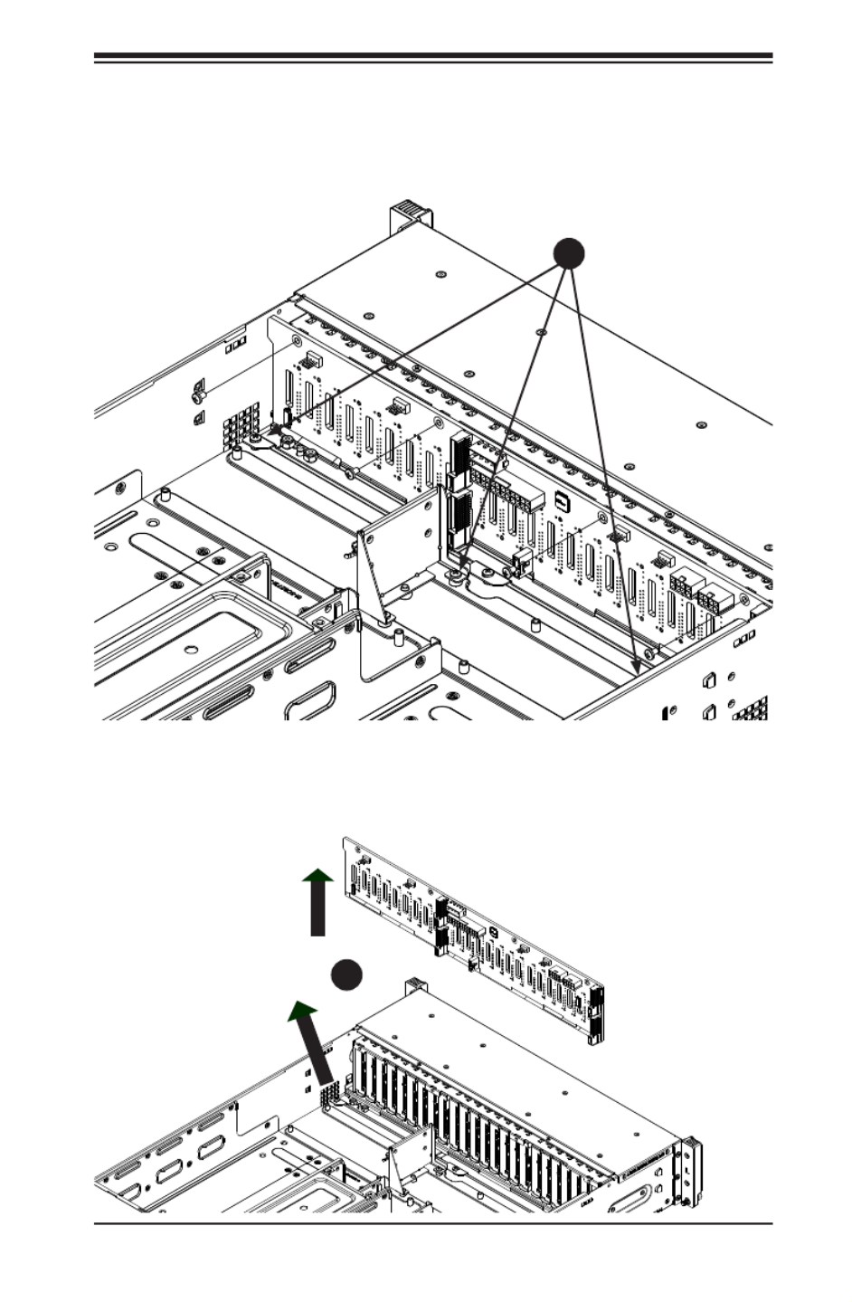
Chapter 6: Advanced Chassis Setup
6-9
6. Loosen the three screws in the spring bar, located on the oor of the chassis,
indicated by the arrows below (Figure 6-7).
7. Gently ease the backplane up and out of the chassis at a slight angle
(Figure 6-8.
Figure 6-7. Loosening the Spring Bar Screws in the Floor of the Chassis
Figure 6-8. Removing the Backplane from the Chassis
1
6
1
7
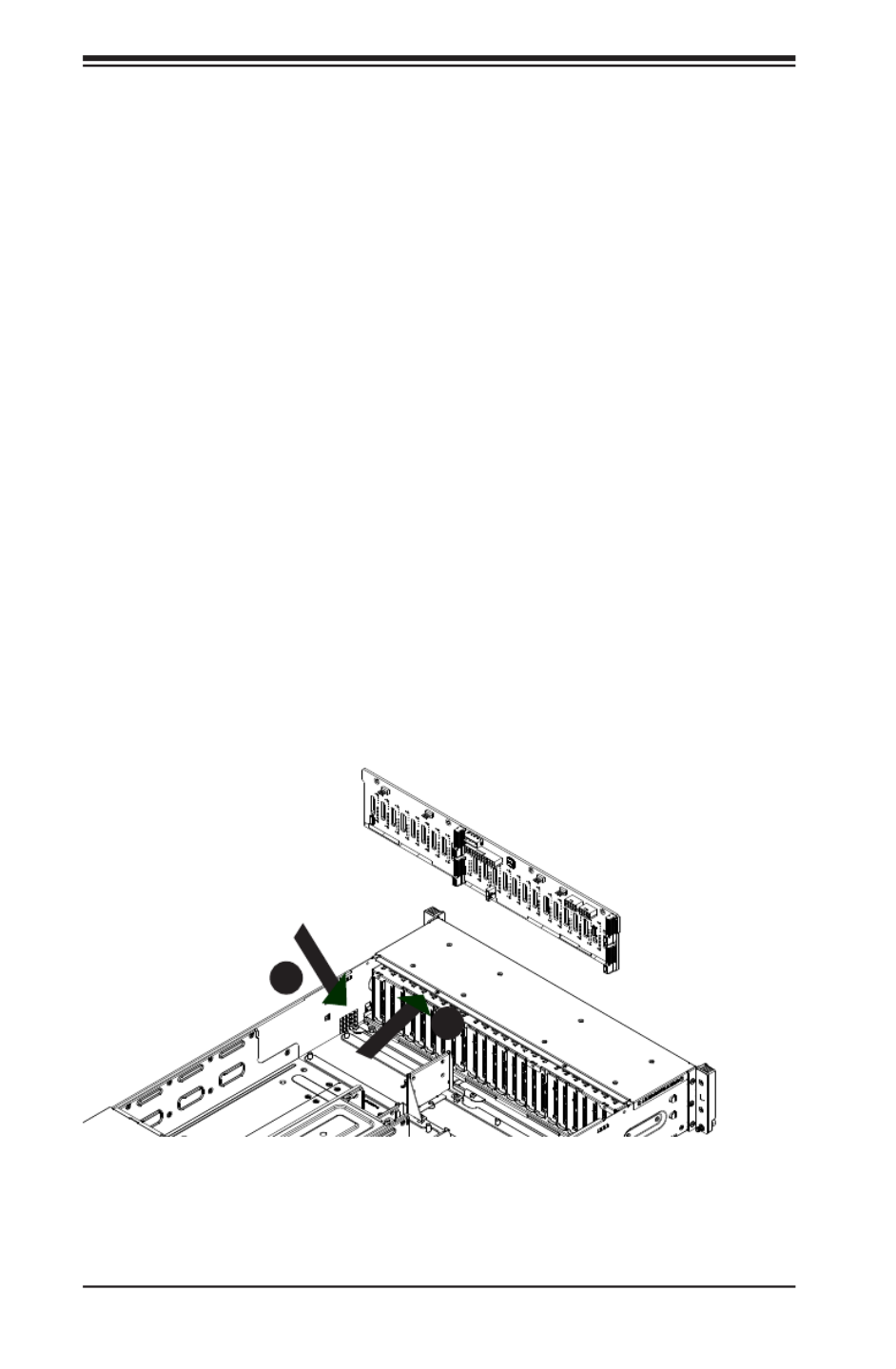
6-10
SUPERSERVER 2028TP-HC0R/HC0TR/HC0FR USER'S MANUAL
Figure 6-9. Installing the Backplane
Installing the Backplane
Installing the Backplane into the Chassis (Figure 6-9)
1. Ensure that all of the hard drive carriers have been removed from the bays in
the front of the chassis and that the spring bar has been loosened as directed
in the previous section.
2. Secure the side mounting bracket to the backplane with the two screws
provided.
3. Slide the backplane into the chassis at a slight angle, pushing it up against
the side of the chassis.
4. Ease the backplane forward, against the front of the chassis. This will aid in
the alignment of the mounting holes.
5. Align the mounting holes in the backplane with the holes in the chassis.
Replace the four screws at the top of the backplane and the screw on the
side of the chassis.
6. Adjust the spring bar, then tighten the spring bar screws in the oor of the
chassis.
7. Reconnect all cables and return the hard drive carriers to their bays in the
front of the chassis.
8. Replace the chassis cover and power-up the system.
1
3
1
4

Chapter 6: Advanced Chassis Setup
6-11
6-8 Installing the Serverboard
I/O Shield
The I/O shield holds the serverboard ports in place. The I/O shield does not require
installation (see Figure 6-10).
Permanent and Optional Standoffs
Standoffs prevent short circuits by creating space between the serverboard and the
chassis surface. The SC217HQ+ chassis includes permanent standoffs in locations
used by the serverboards. These standoffs accept the rounded Phillips head screws
included in the SC217HQ+ accessories packaging.
Some serverboards require additional screws for heatsinks, general components
and/or non-standard security. Optional standoffs are used for these serverboards.
To use an optional standoff, you must place a hexagonal screw through the bottom
the chassis and secure the screw with the hexagonal nut (rounded side up).
Depending upon the conguration of the serverboard being used, it is also possible
that some of the optional standoffs which are pre-installed in the chassis, may need
to be removed.
Installing the Serverboard (Figure 6-11 and 6-12)
1. Review the documentation that came with your serverboard. Become
familiar with component placement, requirements, precautions, and cable
connections.
2. Disconnect the AC power cord from any power source.
3. Pull the serverboard node drawer out of the back of the chassis (Figure 6-11).
4. Remove the expansion card brackets:
3a. Remove screw securing the expansion card bracket to the back of the
node drawer.
3b. Lift the bracket out of the node drawer.
5. Lay the serverboard in the node drawer aligning the standoffs with the
serverboard.
6. Secure the serverboard to the node drawer using the rounded, Phillips head
screws included for this purpose.
7. Install the adapter card associated with the serverboard if the chassis is a
hot-swappable version. Refer to the next section for instructions on installing
the adapter card
8. Secure the CPU(s), heatsinks, and other components to the serverboard as
described in the serverboard documentation.

6-12
SUPERSERVER 2028TP-HC0R/HC0TR/HC0FR USER'S MANUAL
9. Connect the cables between the serverboard, backplane, chassis, front panel,
and power supply, as needed. Also, fans may be temporarily removed to
allow access to the backplane ports.
10. Replace the expansion card bracket and secure the bracket with a screw.
11. Repeat steps 3 - 5 for the remaining nodes.
12. Connect the AC power cord and power up the system.
Figure 6-11. Removing Serverboard Node Drawer

Chapter 6: Advanced Chassis Setup
6-13
Figure 6-12. Installing the Serverboard in the Serverboard Node Drawer

6-14
SUPERSERVER 2028TP-HC0R/HC0TR/HC0FR USER'S MANUAL
Figure 6-13. Adapter Card Installation
6-9 Adapter Card Replacement
Each serverboard drawer comes equipped with an adapter card which plugs into
the backplane. In the unlikely event that the adapter card needs to be replaced,
installation requires only a Phillips head screwdriver.
Removing the Adapter Card (Figure 6-13)
1. Disconnect the AC power cord from any power source.
2. Remove the serverboard drawer from the chassis.
3. Disconnect the wiring, connecting the adapter card to the serverboard if any
is present.
4. Remove the ve screws securing the adapter card and set them aside for
later use.
5. Remove the adapter card from the serverboard drawer.
Installing the Adapter Card (Figure 6-12)
1. Make sure the serverboard has been installed properly in the node drawer
before installing the adapter card
2. Place the adapter card in the serverboard drawer, aligning the holes in the
adapter card with the holes in the serverboard drawer.
3. Secure the adapter card to the serverboard drawer, using the ve M3 athead
screws which were previously set aside.
4. Reconnect the wiring from the serverboard to the adapter card if necessary.
5. Return the serverboard drawer to the closed position in the chassis.
Serverboard
Drawer
Adapter Card
Five Screws
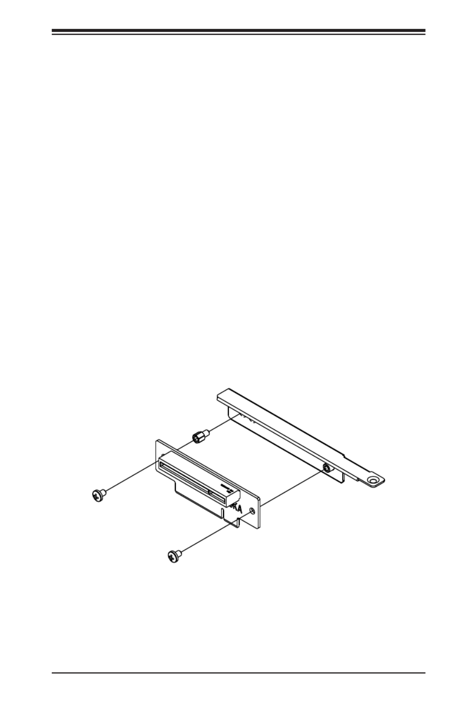
Chapter 6: Advanced Chassis Setup
6-15
Expansion Card/PCI Slot Setup
The SC217HQ+ chassis supports one low-prole expansion PCI slot for each node,
for a total of four PCI slots in the chassis. To install a low-prole PCI card, follow
the following instructions.
Installing the Riser Card
Installing the Riser Card (Figure 6-14)
1. Disconnect the chassis from any power source and lay the chassis on a at
surface.
2. Pull the serverboard node drawer from the chassis.
3. Remove the expansion card bracket.
3a. Remove the screw securing the expansion bracket to the back of the
drawer.
3b. Lift the bracket out of the serverboard node drawer.
4. Align the riser card mounting hole to the bracket standoff and secure the riser
card to the bracket using the two screws included in the accessory box.
5. Inser the riser card along with the riser bracket into the serverboard.
6. Secure the riser bracket to the serverboard node drawer's rear window.
Figure 6-14. Installing the Riser Card

6-16
SUPERSERVER 2028TP-HC0R/HC0TR/HC0FR USER'S MANUAL
Installing Expansion Cards (Figure 6-15)
1. Disconnect the chassis from any power source, lay the chassis on a at
surface, and open the chassis cover.
2. Pull out the serverboard node drawer from the chassis.
3. Pull open the expansion card PCI slot clip in the rear of the serverboard node
drawer.
4. Remove the PCI PCI slot shield.
5. Place the expansion card into the serverboard node drawer.
6. Slide the expansion card into the rear riser card PCI slot and t the expansion
card bracket with the opening in the rear of the serverboard node drawer.
7. Close the expansion card PCI slot clip.
8. Close the cover, reconnect the power supply and power-up the chassis.
Figure 6-15. Installing the Expansion Card
Riser Card
Riser Card
Bracket
Expander Card

Chapter 6: Advanced Chassis Setup
6-17
6-10 Drive Bay Installation/Removal
Accessing the Drive Bays
SATA Drives: You do not need to access the inside of the chassis or remove power
to replace or swap SAS/SATA drives. Proceed to the next step for instructions. You
must use standard 1" high, SATA drives in the system.
Note: Refer to the following FTP site for setup guidelines: <ftp://ftp.supermicro.com/
driver/SAS/LSI/LSI_SAS_EmbMRAID_SWUG.pdf> and Supermicro's web site for
additional inmformation < http://www.supermicro.com/support/manuals/>.
The SC217HQ+ chassis contains four individual motherboards in separate node
drawers. Each serverboard node controls a set of six hard drives. Note that if a
serverboard node drawer is pulled out of the chassis, the hard drives associated
with that node will power down as well.
Serverboard Drawer Locations in the Chassis
Serverboard B
Controls HDDs B1, B2, B3, B4, B5 and B6
Serverboard D
Controls HDDs D1, D2, D3, D4, D5 and D6
Serverboard A
Controls HDDs A1, A2, A3, A4, A5 and A6
Serverboard C
Controls HDDs C1, C2, C3, C4, C5 and C6
Figure 6-16. Hard Drives and the Corresponding Serverboards
SB: A
SB: B
SB: C
SB: D
1
A
1
B
1
C
1
D

6-18
SUPERSERVER 2028TP-HC0R/HC0TR/HC0FR USER'S MANUAL
Removing Hard Drive Trays from the Chassis (Figure 6-17)
1. Press the release button on the drive tray. This extends the drive bay handle.
2. Use the handle to pull the drive out of the chassis.
Figure 6-17. Removing Hard Drive
1
1
1
2
Cauton: Except for short periods of time while swapping hard drives, do not operate
the server with the hard drives empty.
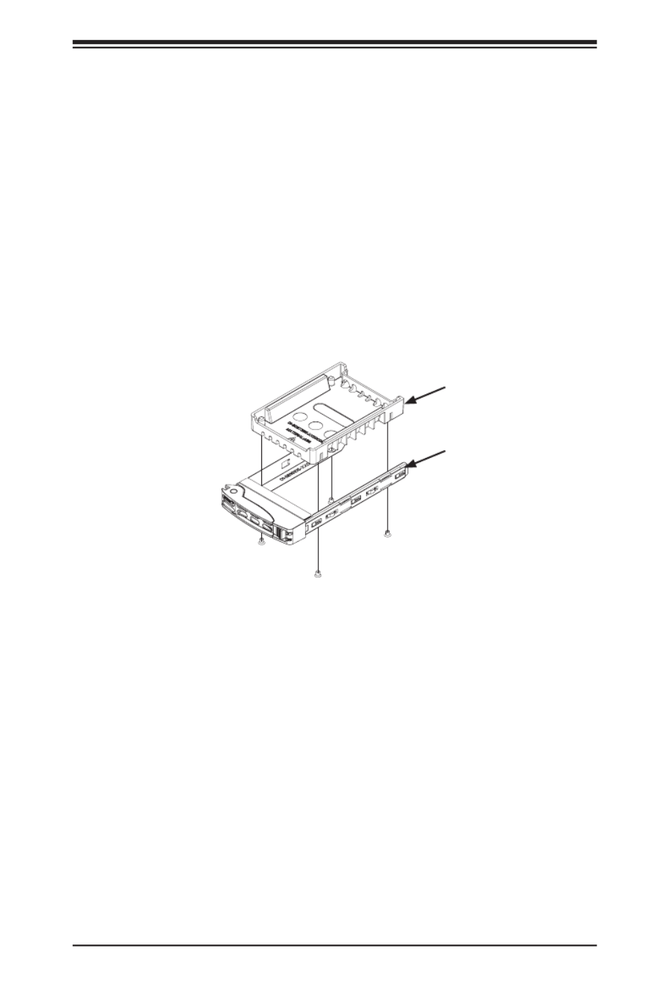
Chapter 6: Advanced Chassis Setup
6-19
Figure 6-18. Chassis Drive Tray
Installing a Drive into the Hard Drive Tray
The drives are mounted in drive carriers to simplify their installation and removal
from the chassis. These carriers also help promote proper airow for the drive bays.
1. Remove the screws (4) holding connecting the drive tray the carrier.
2. Remove the tray from the carrier.
3. Install a new drive into the carrier with the printed circuit board side facing
down so that the mounting holes align with those in the carrier.
4. Secure the hard drive by tightening all four screws.
5. Use the open handle to replace the drive carrier into the chassis. Make sure
to close the drive carrier handle.
Dummy Drive
Hard Drive Carrier
Caution: Enterprise level hard disk drives are recommended for use in Supermicro
chassis and servers. For information on recommended HDDs, visit the Supermicro
Web site at http://www.supermicro.com/products/nfo/les/storage/SAS-CompList.pdf

6-20
SUPERSERVER 2028TP-HC0R/HC0TR/HC0FR USER'S MANUAL
6-11 Power Supply
The SC217HQ+ chassis includes two redundant, hot-plug 2000 Watt power supplies.
This power supply is auto-switching capable. This enables it to automatically sense
and operate at a 100v to 240v input voltage. An amber light will be illuminated on
the power supply when the power is off. An illuminated green light indicates that
the power supply is operating.
Power Supply Replacement
The SC217HQ+ chassis utilizes two redundant power supplies. In the unlikely event
that the power supply unit needs to be replaced, one power supply can be removed,
without powering down the system. Replacement units can be ordered directly from
Supermicro (See the contact information in the Preface of this manual).
Changing the Power Supply
1. Push the release tab (on the back of the power supply) as illustrated.
2. Pull the power supply out using the handle provided.
3. Push the new power supply module into the power bay until it clicks into the
locked position.
Figure 6-19. Changing the Power Supply
Release Tab

Chapter 7: BIOS
7-1
Chapter 7
BIOS
7-1 Introduction
This chapter describes the AMI BIOS setup utility for the X10DRT-P/PT/PIBF. The
ROM BIOS is stored in a Flash EEPROM and can be easily updated. This chapter
describes the basic navigation of the AMI BIOS setup utility screens.
Note: For AMI BIOS recovery, please refer to the UEFI BIOS Recovery
Instructions in Appendix C.
Starting BIOS Setup Utility
To enter the AMI BIOS setup utility screens, press the <Delete> key while the
system is booting up.
Note: In most cases, the <Delete> key is used to invoke the AMI BIOS
setup screen. There are a few cases when other keys are used, such as
<F1>, <F2>, etc.
Each main BIOS menu option is described in this manual. The AMI BIOS setup
menu screen has two main frames. The left frame displays all the options that can
be congured. Grayed-out options cannot be congured. Options in blue can be
congured by the user. The right frame displays the key legend. Above the key
legend is an area reserved for a text message. When an option is selected in the
left frame, it is highlighted in white. Often a text message will accompany it.
Note: the AMI BIOS has default text messages built in. Supermicro retains
the option to include, omit, or change any of these text messages.
The AMI BIOS setup utility uses a key-based navigation system called "hot keys."
Most of the AMI BIOS setup utility "hot keys" can be used at any time during the
setup navigation process. These keys include <F1>, <F4>, <Enter>, <Esc>, arrow
keys, etc.
Note Bold: Options printed in are default settings.
How To Change the Conguration Data
The conguration data that determines the system parameters may be changed by
entering the AMI BIOS setup utility. This setup utility can be accessed by pressing
<Del> at the appropriate time during system boot.

7-2
SUPERSERVER 2028TP-HC0R/HC0TR/HC0FR USER'S MANUAL
How to Start the Setup Utility
Normally, the only visible Power-On Self-Test (POST) routine is the memory test.
As the memory is being tested, press the <Delete> key to enter the main menu of
the AMI BIOS setup utility. From the main menu, you can access the other setup
screens. An AMI BIOS identication string is displayed at the left bottom corner of
the screen, below the copyright message.
Warning: Do not upgrade the BIOS unless your system has a BIOS-related issue.
Flashing the wrong BIOS can cause irreparable damage to the system. In no event shall
Supermicro be liable for direct, indirect, special, incidental, or consequential damages
arising from a BIOS update. If you have to update the BIOS, do not shut down or reset
the system while the BIOS is updating to avoid possible boot failure.
7-2 Main Setup
When you rst enter the AMI BIOS setup utility, you will enter the Main setup screen.
You can always return to the Main setup screen by selecting the Main tab on the
top of the screen. The Main BIOS setup screen is shown below.

Chapter 7: BIOS
7-3
The following Main menu items will be displayed:
System Date/System Time
Use this option to change the system date and time. Highlight System Date or
System Time using the arrow keys. Enter new values using the keyboard. Press the
<Tab> key or the arrow keys to move between elds. The date must be entered in
Day MM/DD/YYYY format. The time is entered in HH:MM:SS format.
Note: The time is in the 24-hour format. For example, 5:30 P.M. appears
as 17:30:00.
Supermicro X10DRT-P Series
BIOS Version: This item displays the version of the BIOS ROM used in the
system.
Build Date: This item displays the date when the version of the BIOS ROM used
in the system was built.
Memory Information
Total Memory: This item displays the total size of memory available in the system.
Memory Speed: This item displays the default speed of the memory modules
installed in the system.

7-4
SUPERSERVER 2028TP-HC0R/HC0TR/HC0FR USER'S MANUAL
7-3 Advanced Setup Congurations
Use the arrow keys to select Advanced setup and press <Enter> to access the
submenu items:
Warning: Take Caution when changing the Advanced settings. An incorrect value, a
very high DRAM frequency or an incorrect BIOS timing setting may cause the system
to malfunction. When this occurs, restore the setting to the manufacture default setting.
Boot Feature
Quiet Boot
Use this feature to select the screen display between POST messages or the OEM
logo at bootup. Select Disabled to display the POST messages. Select Enabled
to display the OEM logo instead of the normal POST messages. The options are
Enabled and Disabled.
AddOn ROM Display Mode
Use this item to set the display mode for the Option ROM. Select Keep Current to
use the current AddOn ROM display setting. Select Force BIOS to use the Option
ROM display mode set by the system BIOS. The options are Force BIOS and
Keep Current.
Bootup Num-Lock State
Use this feature to set the Power-on state for the Numlock key. The options are
Off and On.

Chapter 7: BIOS
7-5
Wait For 'F1' If Error
Select Enabled to force the system to wait until the 'F1' key is pressed if an error
occurs. The options are Disabled and Enabled.
INT19 (Interrupt 19) Trap Response
Interrupt 19 is the software interrupt that handles the boot disk function. When this
item is set to Immediate, the ROM BIOS of the host adaptors will "capture" Inter-
rupt 19 at bootup immediately and allow the drives that are attached to these host
adaptors to function as bootable disks. If this item is set to Postponed, the ROM
BIOS of the host adaptors will not capture Interrupt 19 immediately and allow the
drives attached to these adaptors to function as bootable devices at bootup. The
options are and Postponed. Immediate
Re-try Boot
When EFI Boot is selected, the system BIOS will automatically reboot the system
from an EFI boot device after its initial boot failure. Select Legacy Boot to allow
the BIOS to automatically reboot the system from a Legacy boot device after its
initial boot failure. The options are , Legacy Boot, and EFI Boot.Disabled
Power Conguration
Watch Dog Function
Select Enabled to allow the Watch Dog timer to reboot the system when it is inac-
tive for more than 5 minutes. The options are Enabled and Disabled.
Power Button Function
This feature controls how the system shuts down when the power button is pressed.
Select 4 Seconds Override for the user to power off the system after pressing and
holding the power button for 4 seconds or longer. Select Instant Off to instantly
power off the system as soon as the user presses the power button. The options
are 4 Seconds Override and Instant Off.
Restore on AC Power Loss
Use this feature to set the power state after a power outage. Select Power-Off for
the system power to remain off after a power loss. Select Power-On for the system
power to be turned on after a power loss. Select Last State to allow the system
to resume its last power state before a power loss. The options are Power-On,
Stay-Off and Last State.

7-6
SUPERSERVER 2028TP-HC0R/HC0TR/HC0FR USER'S MANUAL
CPU Conguration
This submenu displays the following CPU information as detected by the BIOS. It
also allows the user to congure CPU settings.
• Processor Socket
• Processor ID
• Processor Frequency
• Processor Max Ratio
• Processor Min Ratio
• Microcode Revision
• L1 Cache RAM
• L2 Cache RAM
• L3 Cache RAM
• CPU 1 Version
• CPU 2 Version
Clock Spread Spectrum
Select Enabled to allow the BIOS to monitor and attempt to reduce the level of
Electromagnetic Interference caused by the components whenever needed. The
options are and Enabled.Disabled
Execute Disable Bit (Available if supported by the OS & the CPU)
Select Enable for Execute Disable Bit Technology support, which will allow the
processor to designate areas in the system memory where an application code can
execute and where it cannot, thus preventing a worm or a virus from ooding illegal
codes to overwhelm the processor to damage the system during an attack. This
feature is used in conjunction with the items: "Clear MCA," "VMX," "Enable SMX,"
and "Lock Chipset" for Virtualization media support. The options are and Enable
Disable. (Refer to Intel and Microsoft websites for more information.)
PPIN Control
Select Unlock/Enable to use the Protected-Processor Inventory Number (PPIN) in
the system. The options are and Unlock/Disable. Unlock/Enable

Chapter 7: BIOS
7-7
Hardware Prefetcher (Available when supported by the CPU)
If set to Enable, the hardware prefetcher will prefetch streams of data and instruc-
tions from the main memory to the L2 cache to improve CPU performance. The
options are Disable and Enable.
Adjacent Cache Line Prefetch (Available when supported by the CPU)
Select Enable for the CPU to prefetch both cache lines for 128 bytes as comprised.
Select Disable for the CPU to prefetch both cache lines for 64 bytes. The options
are Disable and Enable.
Note: Please reboot the system for changes on this setting to take effect.
Please refer to Intel’s website for detailed information.
DCU (Data Cache Unit) Streamer Prefetcher (Available when supported by
the CPU)
If set to Enable, the DCU Streamer Prefetcher will prefetch data streams from the
cache memory to the DCU (Data Cache Unit) to speed up data accessing and
processing to enhance CPU performance. The options are Disable and Enable.
DCU IP Prefetcher
If set to Enable, the IP prefetcher in the DCU (Data Cache Unit) will prefetch IP
addresses to improve network connectivity and system performance. The options
are Enable and Disable.
DCU Mode
Use this feature to set the data-prefecting mode for the DCU (Data Cache Unit).
The options are 32KB 8Way Without ECC and 16KB 4Way With ECC.
Direct Cache Access (DCA)
Select Enable to use Intel DCA (Direct Cache Access) Technology to improve the
efciency of data transferring and accessing. The options are Auto, Enable, and
Disable.
DCA Prefetch Delay
A DCA Prefetcher is used with a TOE (TCP/IP Ofoad Engine) adapter to prefetch
data in order to shorten execution cycles and maximize data processing efciency.
Prefetching data too frequently can saturate the cache directory and delay neces-
sary cache access. This feature reduces or increases the frequency the system
prefetches data. The options are Disable, [8], [16], [24], , [40], [48], [56], [64], [32]
[72], [80], [88], [96], [104], [112].

7-8
SUPERSERVER 2028TP-HC0R/HC0TR/HC0FR USER'S MANUAL
X2 APIC (Advanced Programmable Interrupt Controller)
Based on Intel's Hyper-Threading architecture, each logical processor (thread) is
assigned 256 APIC IDs (APIDs) in 8-bit bandwidth. When this feature is set to En-
able, the APIC ID will be expanded (X2) from 8 bits to 16 bits to provide 512 APIDs
to each thread to enhance CPU performance. The options are Disable and Enable.
AES-NI
Select Enable to use the Intel Advanced Encryption Standard (AES) New Instruc-
tions (NI) to ensure data security. The options are Enable and Disable.
Intel Virtualization Technology
Select Enable to use Intel Virtualization Technology support for Direct I/O VT-d sup-
port by reporting the I/O device assignments to the VMM (Virtual Machine Monitor)
through the DMAR ACPI tables. This feature offers fully-protected I/O resource
sharing across Intel platforms, providing greater reliability, security and availability
in networking and data-sharing. The options are and Disable.Enable
Advanced Power Management Conguration
Advanced Power Management Conguration
Power Technology
Select Energy Efcient to support power-saving mode. Select Custom to custom-
ize system power settings. Select Disabled to disable power-saving settings. The
options are Disable, , and Custom. Energy Efcient
If the option is set to Energy Efcient or Custom, the following items will display:
Cong TDP (Conguring Thermal Design Power)
Select Enable to congure TDP power settings to enhance thermal management.
The options are Enable and Disable.
Cong TDP Level (Available when Cong TDP above is set to Enable)
Use this item to set TDP conguration level to enhance thermal management.
The options are , Level 1, and Level 2.Nominal
CPU P State Control (Available when Power Technology
is set to Custom)
EIST (P-states)
EIST (Enhanced Intel SpeedStep Technology) allows the system to automatically
adjust processor voltage and core frequency to reduce power consumption and
heat dissipation. The options are Disable and Enable.

Chapter 7: BIOS
7-9
P-state Coordination
This feature is used to change the P-state (Power-Performance State) coordi-
nation type. P-state is also known as "SpeedStep" for Intel processors. Select
HW_ALL to change the P-state coordination type for hardware components only.
Select SW_ALL to change the P-state coordination type for all software installed
in the system. Select SW_ANY to change the P-state coordination type for a soft-
ware program in the system. The options are SW_ALL, and SW_ANY.HW_All,
CPU C State Control (Available when Power Technology
is set to Custom)
Package C State limit
Use this item to set the limit on the C-State package register. The options are
C0/1 state, C2 state, C6 (non-Retention) state, and C6 (Retention) state.
CPU C3 Report
Select Enable to allow the BIOS to report the CPU C3 State (ACPI C2) to the
operating system. During the CPU C3 State, the CPU clock generator is turned
off. The options are Enable and Disable.
CPU C6 Report (Available when Power Technology is set to Custom)
Select Enable to allow the BIOS to report the CPU C6 state (ACPI C3) to the
operating system. During the CPU C6 state, power to all cache is turned off.
The options are and Disable.Enable
Enhanced Halt State (C1E)
Select Enabled to use Enhanced Halt-State technology, which will signicantly
reduce the CPU's power consumption by reducing the CPU's clock cycle and
voltage during a Halt-state. The options are Disable and Enable.
CPU T State Control (Available when Power Technology
is set to Custom)
ACPI (Advanced Conguration Power Interface) T-States
Select Enable to support CPU throttling by the operating system to reduce power
consumption. The options are and Disable. Enable

7-10
SUPERSERVER 2028TP-HC0R/HC0TR/HC0FR USER'S MANUAL
Chipset Conguration
Warning! Please set the correct settings for the items below. A wrong conguration
setting may cause the system to become malfunction.
North Bridge
This feature allows the user to congure the settings for the Intel North Bridge.
IIO Conguration
EV DFX (Device Function On-Hide) Features
When this feature is set to Enable, the EV_DFX Lock Bits that are located on a
processor will always remain clear during electric tuning. The options are Dis-
able and Enable.
IIO1 Conguration
IOU2 (II0 PCIe Port 1)
This item congures the PCI-E port Bifuraction setting for a PCI-E port specied
by the user. The options are x4x4, x8, and Auto.
IOU0 (II0 PCIe Port 2)
This item congures the PCI-E port Bifuraction setting for a PCI-E port specied
by the user. The options are x4x4x4x4, x4x4x8, x8x4x4, x8x8, x16, and Auto.
IOU1 (II0 PCIe Port 3)
This item congures the PCI-E port Bifuraction setting for a PCI-E port specied
by the user. The options are x4x4x4x4, x4x4x8, x8x4x4, x8x8, x16, and Auto.
IIO2 Conguration
IOU2 (II0 PCIe Port 1)
This item congures the PCI-E port Bifuraction setting for a PCI-E port specied
by the user. The options are x4x4, x8, and Auto.
PORT 1A Link Speed
This item congures the link speed of a PCI-E port specied by the user. The
options are Gen 1 (Generation 1) (2.5 GT/s), Gen 2 (Generation 2) (5 GT/s),
and Gen 3 (Generation 3) (8 GT/s).

Chapter 7: BIOS
7-11
IOU0 (II0 PCIe Port 2)
This item congures the PCI-E port Bifuraction setting for a PCI-E port specied
by the user. The options are x4x4x4x4, x4x4x8, x8x4x4, x8x8, x16, and Auto.
PORT 2A Link Speed
This item congures the link speed of a PCI-E port specied by the user. The
options are Gen 1 (Generation 1) (2.5 GT/s), Gen 2 (Generation 2) (5 GT/s),
and Gen 3 (Generation 3) (8 GT/s).
PORT 2C Link Speed
This item congures the link speed of a PCI-E port specied by the user. The
options are Gen 1 (Generation 1) (2.5 GT/s), Gen 2 (Generation 2) (5 GT/s),
and Gen 3 (Generation 3) (8 GT/s).
IOU1 (II0 PCIe Port 3)
This item congures the PCI-E port Bifuraction setting for a PCI-E port specied
by the user. The options are x4x4x4x4, x4x4x8, x8x4x4, x8x8, x16, and Auto.
PORT 3A Link Speed
This item congures the link speed of a PCI-E port specied by the user. The
options are Gen 1 (Generation 1) (2.5 GT/s), Gen 2 (Generation 2) (5 GT/s),
and Gen 3 (Generation 3) (8 GT/s).
IOAT (Intel® IO Acceleration) Conguration
Enable IOAT
Select Enable to enable Intel I/OAT (I/O Acceleration Technology) support, which
signicantly reduces CPU overhead by leveraging CPU architectural improve-
ments and freeing the system resource for other tasks. The options are Enable
and Disable.
No Snoop
Select Enable to support no-snoop mode for each CB device. The options are
Disable and Enable.
Relaxed Ordering
Select Enable to enable Relaxed Ordering support which will allow certain
transactions to violate the strict-ordering rules of PCI bus for a transaction to
be completed prior to other transactions that have already been enqueued. The
options are and Enable.Disable

7-12
SUPERSERVER 2028TP-HC0R/HC0TR/HC0FR USER'S MANUAL
Intel VT for Directed I/O (VT-d)
Intel VT for Direct I/O (VT-d)
Intel® VT for Directed I/O (VT-d)
Select Enable to use Intel Virtualization Technology support for Direct I/O VT-d
support by reporting the I/O device assignments to the VMM (Virtual Machine
Monitor) through the DMAR ACPI tables. This feature offers fully-protected I/O
resource sharing across Intel platforms, providing greater reliability, security and
availability in networking and data-sharing. The options are and Disable.Enable
Interrupt Remapping
Select Enable for Interrupt Remapping support to enhance system performance.
The options are and Disable.Enable
Coherency Support (Non-Isoch)
Select Enable for the Non-Iscoh VT-d engine to pass through DMA (Direct Memo-
ry Access) to enhance system performance. The options are and Disable.Enable
Coherency Support (Isoch)
Select Enable for the Iscoh VT-d engine to pass through ATS to enhance system
performance. The options are Enable and Disable.
QPI (Quick Path Interconnect) Conguration
QPI Status
The following information will display:
• Number of CPU
• Number of II0
• Current QPI Link Speed
• Current QPI Link Frequency
• QPI Global MMIO Low Base/Limit
• QPI Global MMIO High Base/Limit
• QPI PCIe Conguration Base/Size

Chapter 7: BIOS
7-13
Link Speed Mode
Use this item to select the data transfer speed for QPI Link connections. The
options are and Slow.Fast
Link Frequency Select
Use this item to select the desired frequency for QPI Link connections. The op-
tions are 6.4GB/s, 8.0GB/s, 9.6GB/s, Auto, and Auto Limited.
Link L0p Enable
Select Enable for Link L0p support. The options are and Disable.Enable
Link L1 Enable
Select Enable for Link L1 support. The options are and Disable.Enable
COD Enable (Available when the OS and the CPU support this feature)
Select Enable for Cluster-On-Die support to enhance system performance in
cloud computing. The options are Enable, Disable, and Auto.
Early Snoop (Available when the OS and the CPU support this feature)
Select Enable for Early Snoop support to enhance system performance. The
options are Enable, Disable, and Auto.
Isoc Mode
Select Enable for Isochronous support to meet QoS (Quality of Service) require-
ments. This feature is especially important for Virtualization Technology. The
options are Enable and Disable.
Memory Conguration
Enforce POR
Select Enabled to enforce POR restrictions on DDR4 frequency and voltage
programming. The options are and Disabled.Enabled
Memory Frequency
Use this feature to set the maximum memory frequency for onboard memory
modules. The options are 1333, 1400, 1600, 1800, 1867, 2000, 2133, Auto,
2200, 2400, 2600, 2667, and Reserved (Do not select Reserved).
ECC Support
Select Enable to enable Error Checking & Correction (ECC) support for onboard
memory modules. The options are , Enable and Disable.Auto

7-14
SUPERSERVER 2028TP-HC0R/HC0TR/HC0FR USER'S MANUAL
Data Scrambling
Select Enabled to enable data scrambling to enhance system performance and
data integrity. The options are , Disabled and Enabled.Auto
DRAM RAPL (Running Average Power Limit) Baseline
Use this feature to set the run-time power-limit baseline for DRAM modules. The
options are Disable, DRAM RAPL Mode 0, and DRAM RAPL Mode 1.
Set Throttling Mode
Throttling improves reliability and reduces power consumption in the proces-
sor via automatic voltage control during processor idle states. The options are
Disabled and CLTT (Closed Loop Thermal Throttling).
Socket Interleave Below 4GB
Select Enable for the memory above the 4G Address space to be split between
two sockets. The options are Enable and Disable.
Channel Interleaving
Use this item to set DIMM channel interleaving mood. The options are Auto,
1-Way Interleave, 2-Way Interleave, 3-Way Interleave, and 4-Way Interleave.
Rank Interleaving
Use this item to select a rank memory interleaving method. The options are Auto,
1-Way, 2-Way, 4-Way, and 8-Way.
A7 Mode
Select Enable to support the A7 (Addressing) mode to improve memory perfor-
mance. The options are and Disable.Enable
DIMM Information
This item displays the status of a DIMM module as detected by the AMI
BIOS.
Memory RAS (Reliability_Availability_Serviceability)
Conguration
Use this submenu to congure the following Memory RAS settings.
RAS Mode
When Disable is selected, RAS is not supported. When Mirror is selected, the
motherboard maintains two identical copies of all data in memory for data backup.
When Lockstep is selected, the motherboard uses two areas of memory to run

Chapter 7: BIOS
7-15
the same set of operations in parallel to boost performance. The options are
Disable, Mirror, and Lockstep Mode.
Lockstep x4 DIMMs
Select Enable to enable Lockstep support for x4 DIMM modules. The options
are Auto, Disabled, and Enabled.
Memory Rank Sparing
Select Enable to enable memory-sparing support for memory ranks to improve
memory performance. The options are and Enabled.Disabled
Patrol Scrub
Patrol Scrubbing is a process that allows the CPU to correct correctable memory
errors detected on a memory module and send the correction to the requestor
(the original source). When this item is set to Enable, the IO hub will read and
write back one cache line every 16K cycles, if there is no delay caused by internal
processing. By using this method, roughly 64 GB of memory behind the IO hub
will be scrubbed every day. The options are and Disable.Enable
Patrol Scrub Interval
This feature allows you to decide how many hours the system should wait before
the next complete patrol scrub is performed. Use the keyboard to enter a value
from 0-24. The Default setting is 24.
Demand Scrub
Demand Scrubbing is a process that allows the CPU to correct correctable
memory errors found on a memory module. When the CPU or I/O issues a
demand-read command, and the read data from memory turns out to be a
correctable error, the error is corrected and sent to the requestor (the original
source). Memory is updated as well. Select Enable to use Demand Scrubbing
for ECC memory correction. The options are and Disable.Enable
Device Tagging
Select Enable to support device tagging. The options are and Enable.Disable

7-16
SUPERSERVER 2028TP-HC0R/HC0TR/HC0FR USER'S MANUAL
South Bridge
The following South Bridge information will display:
USB Conguration
• USB Module Version
• USB Devices
Legacy USB Support
Select Enabled to support onboard legacy USB devices. Select Auto to disable
legacy support if there are no legacy USB devices present. Select Disabled to
have all USB devices available for EFI applications only. The options are Enabled,
Disabled and Auto.
XHCI Hand-Off
This is a work-around solution for operating systems that do not support XHCI (Ex-
tensible Host Controller Interface) hand-off. The XHCI ownership change should be
claimed by the XHCI driver. The settings are and Disabled.Enabled
EHCI Hand-Off
This item is for operating systems that do not support Enhanced Host Controller
Interface (EHCI) hand-off. When this item is enabled, EHCI ownership change will
be claimed by the EHCI driver. The settings are Enabled and Disabled.
USB Mass Storage Driver Support
Select Enabled to support USB mass storage devices. The options are Disabled
and Enabled.
Port 60/64 Emulation
Select Enabled to support I/O port 60h/64h emulation, which will provide complete
legacy USB keyboard support for the operating systems that do not support legacy
USB devices. The options are Disabled and Enabled.
USB 3.0 Support
Select Enabled for USB 3.0 support. The options are Smart Auto, Auto, Enabled,
Disabled, and Manual.
EHCI1
Select Enabled to enable EHCI (Enhanced Host Controller Interface) support on
USB 2.0 connector #1 (-at least one USB 2.0 connector should be enabled for EHCI
support.) The options are Disabled and Enabled.

Chapter 7: BIOS
7-17
EHCI2
Select Enabled to enable EHCI (Enhanced Host Controller Interface) support on
USB 2.0 connector #2 (-at least one USB 2.0 connector should be enabled for EHCI
support.) The options are Disabled and Enabled.
XHCI Pre-Boot Drive
Select Enabled to enable XHCI (Extensible Host Controller Interface) support on a
pre-boot drive specied by the user. The options are Enabled and Disabled.
XHCI Idle L1
Select Enabled for XHCI (Extensible Host Controller Interface) Idle Level 1 sup-
port on a USB 3.0 connector specied by the user. The options are Enabled and
Disabled.
PCH DMI ASPM
Select Enabled to enable ASPM (Active State Power Management) support for a
PCH DMI drive. The options are and Enabled.Disabled

7-18
SUPERSERVER 2028TP-HC0R/HC0TR/HC0FR USER'S MANUAL
SATA Conguration
When this submenu is selected, AMI BIOS automatically detects the presence of
the SATA devices that are supported by the Intel PCH chip and displays the fol-
lowing items:
SATA Controller
This item enables or disables the onboard SATA controller supported by the Intel
PCH chip. The options are and Disabled. Enabled
Congure SATA as
Select IDE to congure a SATA drive specied by the user as an IDE drive. Select
AHCI to congure a SATA drive specied by the user as an AHCI drive. Select
RAID to congure a SATA drive specied by the user as a RAID drive. The options
are IDE, , and RAID. AHCI
*If the item above "Congure SATA as" is set to AHCI, the following items will display:
Support Aggressive Link Power Management
When this item is set to Enabled, the SATA AHCI controller manages the power
usage of the SATA link. The controller will put the link to a low power state when
the I/O is inactive for an extended period of time, and the power state will return
to normal when the I/O becomes active. The options are and Disabled.Enabled
SATA Port 0~ Port 5
This item displays the information detected on the installed SATA drive on the
particular SATA port.
• Model number of drive and capacity
• Software Preserve Support
Port 0~ Port 5
Select Enabled to enable a SATA port specied by the user. The options are
Disabled and Enabled.
Port 0 ~ Port 5 Hot Plug
Select Enabled to enable hot-plugging support for a port specied by the user,
which will allow the user to replace a SATA disk drive installed on this port without
shutting down the system. The options are and Disabled.Enabled
Port 0 ~ Port 5 Spin Up Device
On an edge detect from 0 to 1, set this item to allow the PCH to initialize the
device. The options are Enabled and Disabled.

Chapter 7: BIOS
7-19
Port 0 ~ Port 5 SATA Device Type
Use this item to specify if the SATA port specied by the user should be con-
nected to a Solid State drive or a Hard Disk Drive. The options are Hard Disk
Drive and Solid State Drive.
*If the item above "Congure SATA as" is set to IDE, the following items will
display:
Serial ATA Port 0~ Port 5
This item indicates that a SATA port specied by the user is installed (present)
or not.
Port 0 ~ Port 5 SATA Device Type (Available when a SATA port is
detected)
Use this item to specify if the SATA port specied by the user should be con-
nected to a Solid State drive or a Hard Disk Drive. The options are Hard Disk
Drive and Solid State Drive.
*If the item above "Congure SATA as" is set to RAID, the following items will
display:
Support Aggressive Link Power Management
When this item is set to Enabled, the SATA AHCI controller manages the power
usage of the SATA link. The controller will put the link to a low power state when
the I/O is inactive for an extended period of time, and the power state will return
to normal when the I/O becomes active. The options are and Disabled.Enabled
SATA RAID Option ROM/UEFI Driver
Select EFI to load the EFI driver for system boot. Select Legacy to load a legacy
driver for system boot. The options are Disabled, , and Legacy.EFI
Serial ATA Port 0~ Port 5
This item displays the information detected on the installed SATA drives on the
particular SATA port.
• Model number of drive and capacity
• Software Preserve Support
Port 0~ Port 5
Select Enabled to enable a SATA port specied by the user. The options are
Disabled and Enabled.

Chapter 7: BIOS
7-21
• Software Preserve Support
sSATA Port 0~ Port 3
Select Enabled to enable an sSATA port specied by the user. The options are
Disabled and Enabled.
sSATA Port 0 ~ Port 3 Hot Plug
Select Enabled to enable hot-plugging support for a port specied by the user,
which will allow the user to replace a sSATA disk drive installed on this port
without shutting down the system. The options are and Disabled.Enabled
sSATA Port 0 ~ Port 3 Spin Up Device
On an edge detect from 0 to 1, set this item to allow the PCH to start a COMRE-
SET initialization to the device. The options are Enabled and Disabled.
Port 0 ~ Port 3 sSATA Device Type
Use this item to specify if the sSATA port specied by the user should be con-
nected to a Solid State drive or a Hard Disk Drive. The options are Hard Disk
Drive and Solid State Drive.
*If the item above "Congure sSATA as" is set to IDE, the following items will
display:
sSATA Port 0~ Port 3
This item indicates that an sSATA port specied by the user is installed (pres-
ent) or not.
Port 0 ~ Port 3 sSATA Device Type (Available when a SATA port is
detected)
Use this item to specify if the sSATA port specied by the user should be con-
nected to a Solid State drive or a Hard Disk Drive. The options are Hard Disk
Drive and Solid State Drive.
*If the item above "Congure sSATA as" is set to RAID, the following items will
display:
Support Aggressive Link Power Management
When this item is set to Enabled, the SATA AHCI controller manages the power
usage of the SATA link. The controller will put the link to a low power state when
the I/O is inactive for an extended period of time, and the power state will return
to normal when the I/O becomes active. The options are and Disabled.Enabled

7-22
SUPERSERVER 2028TP-HC0R/HC0TR/HC0FR USER'S MANUAL
sSATA RAID Option ROM/UEFI Driver
Select EFI to load the EFI driver for system boot. Select Legacy to load a legacy
driver for system boot. The options are Disabled, , and Legacy.EFI
sSATA Port 0~ Port 3
This item displays the information detected on the installed sSATA drives on the
particular sSATA port.
• Model number of drive and capacity
• Software Preserve Support
sSATA Port 0~ Port 3
Select Enabled to enable an sSATA port specied by the user. The options are
Disabled and Enabled.
sSATA Port 0 ~ Port 3 Hot Plug
This feature designates this port for hot plugging. Set this item to Enabled for
hot-plugging support, which will allow the user to replace an sSATA drive without
shutting down the system. The options are Enabled and Disabled.
sSATA Port 0 ~ Port 3 Spin Up Device
On an edge detect from 0 to 1, set this item to allow the PCH to start a COMRE-
SET initialization to the device. The options are Enabled and Disabled.
Port 0 ~ Port 3 sSATA Device Type
Use this item to specify if the sSATA port specied by the user should be con-
nected to a Solid State drive or a Hard Disk Drive. The options are Hard Disk
Drive and Solid State Drive.
Server ME (Management Engine) Conguration
This feature displays the following system ME conguration settings.
• General ME Conguration
• Operational Firmware Version
• Recovery Firmware Version
• ME Firmware Features
• ME Firmware Status #1

Chapter 7: BIOS
7-23
• ME Firmware Status #2
• Current State
• Error Code
PCIe/PCI/PnP Conguration
The following PCI information will be displayed:
• PCI Bus Driver Version
• PCI Device Common Settings
PCI Latency Timer
Use this item to congure the PCI latency timer for a device installed on a PCI bus.
Select 32 to set the PCI latency timer to 32 PCI clock cycles. The options are 32,
64, 96, 128, 160, 192, 224, and 248 (PCI Bus Clocks).
VGA Palette Snoop
Select Enabled to support VGA palette register snooping which will allow a PCI
card that does not contain its own VGA color palette to examine a video card pal-
ette and mimic it for proper color display. The options are Disabled and Enabled.
PCI AER (Advanced Error-Reporting) Support
Select Enabled to support Advanced Error-Reporting for onboard PCI devices. The
options are and Enabled.Disabled
Above 4G Decoding (Available if the system supports 64-bit PCI decoding)
Select Enabled to decode a PCI device that supports 64-bit in the space above 4G
Address. The options are Enabled and Disabled.
SR-IOV (Available if the system supports Single-Root Virtualization)
Select Enabled for Single-Root IO Virtualization support. The options are Enabled
and Disabled.
Maximum Payload
Select Auto for the system BIOS to automatically set the maximum payload value
for a PCI-E device to enhance system performance. The options are Auto, 128
Bytes, and 256 Bytes.

Chapter 7: BIOS
7-25
Network Stack
Select Enabled to enable PXE (Preboot Execution Environment) or UEFI (Uni-
ed Extensible Firmware Interface) for network stack support. The options are
Enabled and Disabled.
Super IO Conguration
Super IO Chip AST2400
Serial Port 1 Conguration/Serial Port 2 Conguration
Serial Port 1/Serial Port 2
Select Enabled to enable the onboard serial port specied by the user. The options
are Enabled and Disabled.
Device Settings
This item displays the base I/O port address and the Interrupt Request address of
a serial port specied by the user.
Change Port 1 Settings/Change Port 2 Settings
This feature species the base I/O port address and the Interrupt Request address
of Serial Port 1 or Serial Port 2. Select for the BIOS to automatically assign Auto
the base I/O and IRQ address to a serial port specied.
The options for Serial Port 1 are , (IO=3F8h; IRQ=4), (IO=3F8h; IRQ=3, 4, 5, Auto
6, 7, 9, 10, 11, 12), (IO=2F8h; IRQ=3, 4, 5, 6, 7, 9, 10, 11, 12); (IO=3E8h; IRQ=3,
4, 5, 6, 7, 9, 10, 11, 12), and (IO=2E8h; IRQ=3, 4, 5, 6, 7, 9, 10, 11, 12).
The options for Serial Port 2 are , (IO=3F8h; IRQ=4), (IO=3F8h; IRQ=3, 4, 5, Auto
6, 7, 9, 10, 11, 12), (IO=2F8h; IRQ=3, 4, 5, 6, 7, 9, 10, 11, 12); (IO=3E8h; IRQ=3,
4, 5, 6, 7, 9, 10, 11, 12), and (IO=2E8h; IRQ=3, 4, 5, 6, 7, 9, 10, 11, 12).
Serial Port 2 Attribute
Select SOL to use COM Port 2 as a Serial_Over_LAN (SOL) port for console redi-
rection. The options are COM and SOL.
Serial Port Console Redirection
COM 1
COM 1 Console Redirection
Select Enabled to enable COM Port 1 Console Redirection, which will allow a client
machine to be connected to a host machine at a remote site for networking. The
options are and Enabled.Disabled

7-26
SUPERSERVER 2028TP-HC0R/HC0TR/HC0FR USER'S MANUAL
*If the item above set to Enabled, the following items will become available for
conguration:
COM1 Console Redirection Settings
Terminal Type
This feature allows the user to select the target terminal emulation type for Con-
sole Redirection. Select VT100 to use the ASCII Character set. Select VT100+ to
add color and function key support. Select ANSI to use the Extended ASCII Char-
acter Set. Select VT-UTF8 to use UTF8 encoding to map Unicode characters
into one or more bytes. The options are ANSI, VT100, , and VT-UTF8. VT100+
Bits Per second
Use this item to set the transmission speed for a serial port used in Console
Redirection. Make sure that the same speed is used in the host computer and the
client computer. A lower transmission speed may be required for long and busy
lines. The options are 9600, 19200, 38400, 57600 and 115200 (bits per second).
Data Bits
Use this feature to set the data transmission size for Console Redirection. The
options are 7 (Bits) and 8 (Bits).
Parity
A parity bit can be sent along with regular data bits to detect data transmission
errors. Select Even if the parity bit is set to 0, and the number of 1's in data bits
is even. Select Odd if the parity bit is set to 0, and the number of 1's in data bits
is odd. Select None if you do not want to send a parity bit with your data bits
in transmission. Select Mark to add a mark as a parity bit to be sent along with
the data bits. Select Space to add a Space as a parity bit to be sent with your
data bits. The options are , Even, Odd, Mark and Space.None
Stop Bits
A stop bit indicates the end of a serial data packet. Select 1 Stop Bit for standard
serial data communication. Select 2 Stop Bits if slower devices are used. The
options are and 2.1
Flow Control
Use this item to set the ow control for Console Redirection to prevent data
loss caused by buffer overow. Send a "Stop" signal to stop sending data when
the receiving buffer is full. Send a "Start" signal to start sending data when the
receiving buffer is empty. The options are and Hardware RTS/CTS.None

7-28
SUPERSERVER 2028TP-HC0R/HC0TR/HC0FR USER'S MANUAL
SOL/COM2 Console Redirection Settings
Use this feature to specify how the host computer will exchange data with the client
computer, which is the remote computer used by the user.
Terminal Type
Use this feature to select the target terminal emulation type for Console Redirec-
tion. Select VT100 to use the ASCII Character set. Select VT100+ to add color
and function key support. Select ANSI to use the Extended ASCII Character Set.
Select VT-UTF8 to use UTF8 encoding to map Unicode characters into one or
more bytes. The options are ANSI, VT100, , and VT-UTF8. VT100+
Bits Per second
Use this feature to set the transmission speed for a serial port used in Console
Redirection. Make sure that the same speed is used in the host computer and the
client computer. A lower transmission speed may be required for long and busy
lines. The options are 9600, 19200, 38400, 57600 and 115200 (bits per second).
Data Bits
Use this feature to set the data transmission size for Console Redirection. The
options are 7 (Bits) and 8 (Bits).
Parity
A parity bit can be sent along with regular data bits to detect data transmission
errors. Select Even if the parity bit is set to 0, and the number of 1's in data bits
is even. Select Odd if the parity bit is set to 0, and the number of 1's in data bits
is odd. Select None if you do not want to send a parity bit with your data bits
in transmission. Select Mark to add a mark as a parity bit to be sent along with
the data bits. Select Space to add a Space as a parity bit to be sent with your
data bits. The options are , Even, Odd, Mark and Space.None
Stop Bits
A stop bit indicates the end of a serial data packet. Select 1 Stop Bit for standard
serial data communication. Select 2 Stop Bits if slower devices are used. The
options are and 2.1
Flow Control
Use this feature to set the ow control for Console Redirection to prevent data
loss caused by buffer overow. Send a "Stop" signal to stop sending data when
the receiving buffer is full. Send a "Start" signal to start data-sending when the
receiving buffer is empty. The options are and Hardware RTS/CTS.None

Chapter 7: BIOS
7-29
VT-UTF8 Combo Key Support
Select Enabled to enable VT-UTF8 Combination Key support for ANSI/VT100
terminals. The options are and DisabledEnabled .
Recorder Mode
Select Enabled to capture the data displayed on a terminal and send it as text
messages to a remote server. The options are and Enabled.Disabled
Resolution 100x31
Select Enabled for extended-terminal resolution support. The options are Dis-
abled and Enabled.
Legacy OS Redirection Resolution
Use this feature to select the number of rows and columns used in Console
Redirection for legacy OS support. The options are 80x24 and 80x25.
Putty KeyPad
This feature selects Function Keys and KeyPad settings for Putty, which is a
terminal emulator designed for the Windows OS. The options are , LINUX, VT100
XTERMR6, SCO, ESCN, and VT400.
Redirection After BIOS Post
Use this feature to enable or disable legacy Console Redirection after BIOS
POST (Power-On Self-Test). When this feature is set to Bootloader, legacy
Console Redirection is disabled before booting the OS. When this feature is set
to Always Enable, legacy Console Redirection remains enabled upon OS boot.
The options are and Bootloader.Always Enable
Serial Port for Out-of-Band Management/Windows Emergency Management
Services (EMS)
The submenu allows the user to congure Console Redirection settings to support
Out-of-Band Serial Port management.
EMS Console Redirection
Select Enabled to use a COM port selected by the user for EMS Console Redirec-
tion. The options are Enabled and Disabled.
*If the item above set to Enabled, the following items will become available for
user's conguration:

7-30
SUPERSERVER 2028TP-HC0R/HC0TR/HC0FR USER'S MANUAL
EMS Console Redirection Settings (Available when EMS
Console Redirection is enabled)
Use this feature to specify how the host computer will exchange data with the client
computer, which is the remote computer used by the user.
Out-of-Band Management Port
The feature selects a serial port in a client server to be used by the Windows
Emergency Management Services (EMS) to communicate with a remote host
server. The options are and COM2/SOL (Console COM1 (Console Redirection)
Redirection).
Terminal Type
Use this feature to select the target terminal emulation type for Console Redirec-
tion. Select VT100 to use the ASCII character set. Select VT100+ to add color
and function key support. Select ANSI to use the extended ASCII character set.
Select VT-UTF8 to use UTF8 encoding to map Unicode characters into one or
more bytes. The options are ANSI, VT100, VT100+, and VT-UTF8.
Bits Per Second
This item sets the transmission speed for a serial port used in Console Redirec-
tion. Make sure that the same speed is used in both host computer and the client
computer. A lower transmission speed may be required for long and busy lines.
The options are 9600, 19200, 57600, and 115200 (bits per second).
Flow Control
Use this item to set the ow control for Console Redirection to prevent data
loss caused by buffer overow. Send a "Stop" signal to stop data-sending when
the receiving buffer is full. Send a "Start" signal to start data-sending when
the receiving buffer is empty. The options are Hardware RTS/CTS, and None,
Software Xon/Xoff.
The setting for each these features is displayed:
Data Bits, Parity, Stop Bits
Trusted Computing (Available when a TPM device is
installed and detected by the BIOS)
Conguration
Security Device Support
If this feature and the TPM jumper on the motherboard are both set to Enabled,
onboard security devices will be enabled for TPM (Trusted Platform Module) sup-

Chapter 7: BIOS
7-31
port to enhance data integrity and network security. Please reboot the system for
a change on this setting to take effect. The options are Enabled and Disabled.
TPM State
Select Enabled to use TPM (Trusted Platform Module) settings to enhance system
data security. Please reboot your system for any change on the TPM state to take
effect. The options are Disabled and Enabled.
Pending Operation
Use this item to schedule a TPM-related operation to be performed by a security
device for system data integrity. Your system will reboot to carry out a pending TPM
operation. The options are , Enable Take Ownership, Disable Take Ownership, 0
and TPM Clear.
Note: Your system will reboot to carry out a pending TPM operation.
Current Status Information
This item displays the status of the TPM support on this motherboard.
ACPI Settings
WHEA Support
Select Enabled to support the Windows Hardware Error Architecture (WHEA) plat-
form and provide a common infrastructure for the system to handle hardware errors
within the Windows OS environment to reduce system crashes and to enhance
system recovery and health monitoring. The options are Enabled and Disabled.
High Precision Timer
Select Enabled to activate the High Precision Event Timer (HPET) that produces
periodic interrupts at a much higher frequency than a Real-time Clock (RTC) does in
synchronizing multimedia streams, providing smooth playback and reducing the de-
pendency on other timestamp calculation devices, such as an x86 RDTSC Instruc-
tion embedded in the CPU. The High Performance Event Timer is used to replace
the 8254 Programmable Interval Timer. The options are and Disabled. Enabled
NUMA (Available when the OS supports this feature)
Select Enabled to enable Non-Uniform Memory Access support to enhance system
performance. The options are and Disabled. Enabled

7-32
SUPERSERVER 2028TP-HC0R/HC0TR/HC0FR USER'S MANUAL
7-4 Event Logs
Use this feature to congure Event Log settings.
Change SMBIOS Event Log Settings
This feature allows the user to congure SMBIOS Event settings.
Enabling/Disabling Options
SMBIOS Event Log
Select Enabled to enable SMBIOS (System Management BIOS) Event Logging
during system boot. The options are and Disabled.Enabled
Runtime Error Logging Support
Select Enable to support Runtime Error Logging. The options are Enable and Dis-
able. If this item is set to Enable, the following item will be available for conguration:
Memory Corrected Error Enabling (Available when the item above-Runtime
Error Logging Support is set to Enable)
Select Enable for the BIOS to correct a memory error if it is correctable. The options
are Enable and Disable.
PCI-Ex (PCI-Express) Error Enable
Select Yes for the BIOS to correct errors occurred in the PCI-E slots. The options
are Yes and No.
Memory Correctable Error Threshold
Use this item to enter the threshold value for correctable memory errors. The default
setting is 10.

Chapter 7: BIOS
7-33
Erasing Settings
Erase Event Log
Select Yes to erase all error events in the SMBIOS (System Management BIOS)
log before an event logging is initialized at bootup. The options are No and Yes.
When Log is Full
Select Erase Immediately to immediately erase all errors in the SMBIOS event log
when the event log is full. Select Do Nothing for the system to do nothing when
the SMBIOS event log is full. The options are Do Nothing and Erase Immediately.
SMBIOS Event Log Standard Settings
Log System Boot Event
Select Enabled to log system boot events. The options are and Enabled.Disabled
MECI (Multiple Event Count Increment)
Enter the increment value for the multiple event counter. Enter a number between
1 to 255. The default setting is 1.
METW (Multiple Event Count Time Window)
This item is used to determine how long (in minutes) the multiple event counter
should wait before generating a new event log. Enter a number between 0 to 99.
The default setting is 60.
Note: Please reboot the system for the changes to take effect.
View SMBIOS Event Log
This item allows the user to view the event in the SMBIOS event log. Select this
item and press <Enter> to view the status of an event in the log. The following
categories are displayed:
Date/Time/Error Code/Severity
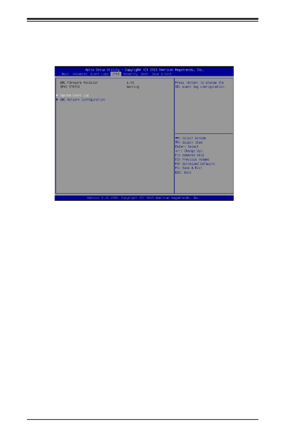
7-34
SUPERSERVER 2028TP-HC0R/HC0TR/HC0FR USER'S MANUAL
7-5 IPMI
Use this feature to congure Intelligent Platform Management Interface (IPMI)
settings.
BMC (BaseBoard Management Controller) Firmware Revision
This item indicates the BMC rmware revision used in your system.
IPMI Status
This item indicates the status of the IPMI rmware installed in your system.
System Event Log
Enabling/Disabling Options
SEL Components
Select Enabled to enable all system event logging support at bootup. The options
are Enabled and Disabled.
Erasing Settings
Erase SEL
Select Yes, On next reset to erase all system event logs upon next system reboot.
Select Yes, On every reset to erase all system event logs upon each system reboot.
Select No to keep all system event logs after each system reboot. The options are
No, Yes, On next reset, and Yes, On every reset.

Chapter 7: BIOS
7-35
When SEL is Full
This feature allows the user to determine what the AMI BIOS should do when the
system event log is full. Select Erase Immediately to erase all events in the log when
the system event log is full. The options are and Erase Immediately.Do Nothing
Note: After making changes on a setting, be sure to reboot the system for
the changes to take effect.
BMC Network Conguration
The following items will be displayed:
• IPMI LAN Selection
• IPMI Network Link Status
Update IPMI LAN Conguration
Select Yes for the system BIOS to automatically reset the following IPMI settings
at next system boot. The options are Yes and No.
Conguration Address Source (Available when the item above - Update
IPMI LAN Conguration is set to Yes)
Use this item to select the IP address source for this computer. If Static is selected,
you will need to know the IP address of this computer and enter it to the system
manually in the eld. If DHCP is selected, AMI BIOS will search for a DHCP (Dy-
namic Host Conguration Protocol) server attached to the network and request
the next available IP address for this computer. The options are and Static. DHCP
Station IP Address
This item displays the Station IP address for this computer. This should be in decimal
and in dotted quad form (i.e., 192.168.10.253).
Subnet Mask
This item displays the sub-network that this computer belongs to. The value of each
three-digit number is separated by dots and it should not exceed 255.
Station MAC Address
This item displays the Station MAC address for this computer. Mac addresses are
6 two-digit hexadecimal numbers.
Gateway IP Address
This item displays the Gateway IP address for this computer. This should be in
decimal and in dotted quad form (i.e., 192.168.10.253).
Produktspecifikationer
| Varumärke: | Supermicro |
| Kategori: | Server |
| Modell: | SuperServer 2028TP-HC0R |
Behöver du hjälp?
Om du behöver hjälp med Supermicro SuperServer 2028TP-HC0R ställ en fråga nedan och andra användare kommer att svara dig
Server Supermicro Manualer

31 Januari 2025
25 Januari 2025
9 Januari 2025
29 December 2024
29 December 2024
29 December 2024
29 December 2024
29 December 2024
29 December 2024
29 December 2024
Server Manualer
- Server Sony
- Server HP
- Server Medion
- Server Toshiba
- Server Abus
- Server Acer
- Server Allnet
- Server Apc
- Server Acti
- Server Hikvision
- Server Asus
- Server SilverStone
- Server Megasat
- Server Maxdata
- Server Lenovo
- Server Black Box
- Server Tripp Lite
- Server Axis
- Server Gigabyte
- Server Nec
- Server Technics
- Server Cisco
- Server AVerMedia
- Server Matrox
- Server Flir
- Server Fujitsu
- Server Digitus
- Server Kathrein
- Server Asrock
- Server Linksys
- Server Buffalo
- Server GeoVision
- Server Netgear
- Server LevelOne
- Server QNAP
- Server LaCie
- Server Dell
- Server Valcom
- Server Asustor
- Server Planet
- Server ZyXEL
- Server Western Digital
- Server Intel
- Server Fantec
- Server MSI
- Server D-Link
- Server Freecom
- Server Eaton
- Server Seagate
- Server Iomega
- Server Synology
- Server Elac
- Server Blackmagic Design
- Server ATen
- Server Veritas
- Server Digi
- Server Revox
- Server Conceptronic
- Server Gefen
- Server Luxman
- Server Quantum
- Server Areca
- Server SEH
- Server Ibm
- Server Provision ISR
- Server Sonnet
- Server Monacor
- Server TAIDEN
- Server Moxa
- Server Smart-AVI
- Server StarTech.com
- Server SIIG
- Server Advantech
- Server Extron
- Server KanexPro
- Server Avocent
- Server Intellinet
- Server Teradek
- Server Vimar
- Server Silex
- Server Kramer
- Server Hanwha
- Server In Win
- Server Lindy
- Server Ernitec
- Server Sun
- Server Atlona
- Server MvixUSA
- Server Dual Bay
- Server Raidsonic
- Server EMC
- Server AMX
- Server Rocstor
- Server Infortrend
- Server Opengear
- Server G-Technology
- Server EXSYS
- Server Raritan
- Server Chenbro Micom
- Server Middle Atlantic
- Server Mr. Signal
- Server Atlantis Land
- Server C2G
- Server Lantronix
- Server Promise Technology
- Server HGST
- Server IStarUSA
- Server NETSCOUT
- Server Mobotix
- Server Origin Storage
Nyaste Server Manualer
9 April 2025
3 April 2025
2 April 2025
2 April 2025
1 April 2025
29 Mars 2025
29 Mars 2025
29 Mars 2025
10 Mars 2025
10 Mars 2025