Supermicro X9DRT-HF Bruksanvisning
Supermicro
moderkort
X9DRT-HF
Läs nedan 📖 manual på svenska för Supermicro X9DRT-HF (105 sidor) i kategorin moderkort. Denna guide var användbar för 5 personer och betygsatt med 4.5 stjärnor i genomsnitt av 2 användare
Sida 1/105

USER’S MANUAL
Revision 1.0c
X9DRT-HF
X9DRT-HIBQF
X9DRT-HIBFF

Manual Revision 1.0c
Release Date: Novmeber 26, 2013
Unless you request and receive written permission from Super Micro Computer, Inc., you may not
copy any part of this document.
Information in this document is subject to change without notice. Other products and companies
referred to herein are trademarks or registered trademarks of their respective companies or mark
holders.
Copyright © 2013 by Super Micro Computer, Inc.
All rights reserved.
Printed in the United States of America
The information in this User’s Manual has been carefully reviewed and is believed to be accurate.
The vendor assumes no responsibility for any inaccuracies that may be contained in this document,
and makes no commitment to update or to keep current the information in this manual, or to notify
any person or organization of the updates. Please Note: For the most up-to-date version of this
manual, please see our Website at www.supermicro.com.
Super Micro Computer, Inc. ("Supermicro") reserves the right to make changes to the product
described in this manual at any time and without notice. This product, including software and docu-
mentation, is the property of Supermicro and/or its licensors, and is supplied only under a license.
Any use or reproduction of this product is not allowed, except as expressly permitted by the terms
of said license.
IN NO EVENT WILL SUPER MICRO COMPUTER, INC. BE LIABLE FOR DIRECT, INDIRECT,
SPECIAL, INCIDENTAL, SPECULATIVE OR CONSEQUENTIAL DAMAGES ARISING FROM THE
USE OR INABILITY TO USE THIS PRODUCT OR DOCUMENTATION, EVEN IF ADVISED OF
THE POSSIBILITY OF SUCH DAMAGES. IN PARTICULAR, SUPER MICRO COMPUTER, INC.
SHALL NOT HAVE LIABILITY FOR ANY HARDWARE, SOFTWARE, OR DATA STORED OR USED
WITH THE PRODUCT, INCLUDING THE COSTS OF REPAIRING, REPLACING, INTEGRATING,
INSTALLING OR RECOVERING SUCH HARDWARE, SOFTWARE, OR DATA.
Any disputes arising between the manufacturer and the customer shall be governed by the laws of
Santa Clara County in the State of California, USA. The State of California, County of Santa Clara
shall be the exclusive venue for the resolution of any such disputes. Supermicro's total liability for
all claims will not exceed the price paid for the hardware product.
FCC Statement: This equipment has been tested and found to comply with the limits for a Class
A digital device pursuant to Part 15 of the FCC Rules. These limits are designed to provide
reasonable protection against harmful interference when the equipment is operated in a commercial
environment. This equipment generates, uses, and can radiate radio frequency energy and, if not
installed and used in accordance with the manufacturer’s instruction manual, may cause harmful
interference with radio communications. Operation of this equipment in a residential area is likely
to cause harmful interference, in which case you will be required to correct the interference at your
own expense.
California Best Management Practices Regulations for Perchlorate Materials: This Perchlorate
warning applies only to products containing CR (Manganese Dioxide) Lithium coin cells. “Perchlorate
Material-special handling may apply. See www.dtsc.ca.gov/hazardouswaste/perchlorate”.
WARNING: Handling of lead solder materials used in this
product may expose you to lead, a chemical known to
the State of California to cause birth defects and other
reproductive harm.

Preface
This manual is written for sy stem in tegrators, PC techn icians and
knowledgeable PC users. It provides information for the installation and use of the
X9DRT-HF/HIBQF/HIBFF motherboard.
About This Motherboard
The Super X9DRT-HF/HIBQF/HIBFF motherboard supports dual Intel
® E5-2600(v2)
Series Processors (Socket R LGA 2011) that offer QPI (Intel QuickPath Interface)
Technology, providing point-to-point connection with a transfer speed of up to 8.0
TG/s. With the PCH C602 built in, the X9DRT-HF/HIBQF/HIBFF motherboard sup-
ports Intel® Management Engine, Rapid Storage Technology, Digital Media Interface
(DMI), PCI-E Gen. 3.0, and up to 1866 MHz DDR3 memory. This motherboard is
ideal for 2U server platforms. Please refer to our website (http://www.supermicro.
com) for processor and memory support updates.
Manual Organization
Chapter 1 describes the features, specications and performance of the moth-
erboard. It also provides detailed information about the Intel PCH C602 chipset.
Chapter 2 provides hardware installation instructions. Read this chapter when in-
stalling the processor, memory modules, and other hardware components into the
system. If you encounter any problems, see , which describes troubleChapter 3 -
shooting procedures for video, memory, and system setup stored in CMOS.
Chapter 4 includes an introduction to BIOS, and provides detailed information on
running the CMOS Setup utility.
Appendix A provides BIOS Error Beep Codes.
Appendix B lists software installation instructions.
Preface
iii

iv
Conventions Used in the Manual
Pay special attention to the following symbols for proper system installation and to
prevent damage to the system or injury to yourself:
Warning: Important information given to ensure proper system installation or to prevent
damage to the components
Note: Additional information given to differentiate between various models
or provides information for proper system setup.
X9DRT-HF/HIBQF/HIBFF Motherboard User’s Manual

Preface
v
Contacting Supermicro
Headquarters
Address: Super Micro Computer, Inc.
980 Rock Ave.
San Jose, CA 95131 U.S.A.
Tel: +1 (408) 503-8000
Fax: +1 (408) 503-8008
Email: marketing@supermicro.com (General Information)
support@supermicro.com (Technical Support)
Web Site: www.supermicro.com
Europe
Address: Super Micro Computer B.V.
Het Sterrenbeeld 28, 5215 ML
's-Hertogenbosch, The Netherlands
Tel: +31 (0) 73-6400390
Fax: +31 (0) 73-6416525
Email: sales@supermicro.nl (General Information)
support@supermicro.nl (Technical Support)
rma@supermicro.nl (Customer Support)
Asia-Pacic
Address: Super Micro Computer, Inc.
3F, No. 150, Jian 1st Rd.
Zhonghe Dist., New Taipei City 23511
Taiwan (R.O.C)
Tel: +886-(2) 8226-3990
Fax: +886-(2) 8226-3992
Web Site: www.supermicro.com.tw
Technical Support:
Email: support@supermicro.com.tw
Tel: +886-(2)-8226-3990

vi
Table of Contents
Preface
Chapter 1 Overview
1-1 Overview ......................................................................................................... 1-1
1-2 Processor and Chipset Overview...................................................................1-11
1-3 Special Features ........................................................................................... 1-12
1-4 PC Health Monitoring .................................................................................... 1-12
1-5 ACPI Features ............................................................................................... 1-13
1-6 Power Supply ................................................................................................ 1-13
1-7 Super I/O ....................................................................................................... 1-14
1-8 Advanced Power Management ..................................................................... 1-14
Intel® Intelligent Power Node Manager (NM) (Available when the NMView
software is installed) ..................................................................................... 1-14
Management Engine (ME) ............................................................................ 1-14
1-9 Overview of the Nuvoton WPCM450 Controller ........................................... 1-14
WPCM450R PCI System Interface ............................................................... 1-15
Chapter 2 Installation
2-1 Standardized Warning Statements ................................................................. 2-1
Battery Handling .............................................................................................. 2-1
Product Disposal ............................................................................................. 2-3
2-2 Static-Sensitive Devices .................................................................................. 2-4
Precautions 2-4 .....................................................................................................
Unpacking 2-4 .......................................................................................................
2-3 Processor and Heatsink Installation................................................................ 2-5
Installing the LGA2011 Processor ................................................................. 2-5
Installing a Passive CPU Heatsink ................................................................. 2-9
Removing the Passive Heatsink ................................................................... 2-10
2-4 Installing and Removing the Memory Modules ..............................................2-11
Installing & Removing DIMMs ........................................................................2-11
Removing Memory Modules ..........................................................................2-11
2-5 Motherboard Installation ................................................................................ 2-16
Tools Needed ................................................................................................ 2-16
Location of Mounting Holes .......................................................................... 2-16
Installing the Motherboard ............................................................................ 2-17
2-6 Control Panel Connectors and I/O Ports ...................................................... 2-18
Back Panel Connectors and I/O Ports .......................................................... 2-18
Back Panel I/O Port Locations and Denitions ........................................... 2-18
X9DRT-HF/HIBQF/HIBFF Motherboard User’s Manual

vii
Table of Contents
Universal Serial Bus (USB) ...................................................................... 2-19
Ethernet Ports .......................................................................................... 2-20
Serial Ports ............................................................................................... 2-21
Video Connector ....................................................................................... 2-21
InniBand Connection (For X9DRT-HIBQF/HIBFF) ................................. 2-22
Unit Identier Switches ............................................................................. 2-23
Front Panel Accessible Add-on Card Header (JF2) ..................................... 2-24
2-7 Connecting Cables ........................................................................................ 2-25
NMI Header .............................................................................................. 2-25
IPMB I2C SMB .......................................................................................... 2-25
System Reset ........................................................................................... 2-26
DOM Power Connector ............................................................................ 2-26
TPM Header/Port 80 ................................................................................ 2-27
2-8 Jumper Settings ............................................................................................ 2-28
Explanation of Jumpers ................................................................................ 2-28
GLAN Enable/Disable .............................................................................. 2-28
CMOS Clear ............................................................................................. 2-29
Watch Dog Enable/Disable ...................................................................... 2-29
VGA Enable .............................................................................................. 2-30
BMC Enable ............................................................................................ 2-30
I2C Bus to PCI-Exp. Slots ........................................................................ 2-31
InniBand (IB) Enable (For X9DRT-HIBQF/HIBFF) ................................. 2-31
Management Engine (ME) Recovery ...................................................... 2-32
Manufacture Mode Select ........................................................................ 2-32
2-9 Onboard LED Indicators ............................................................................... 2-33
GLAN LEDs .............................................................................................. 2-33
IPMI Dedicated LAN LEDs ....................................................................... 2-33
Onboard Power LED ............................................................................... 2-34
BMC Heartbeat LED ................................................................................ 2-34
InniBand LED Indicators (LEB1/LEB2) (For the X9DRT-HIBQF/HIBFF
Only) 2-35 .........................................................................................................
HDD/SATA LED (LE3) .............................................................................. 2-35
Rear UID LED ......................................................................................... 2-36
2-10 PCI-Express and Serial ATA Connections .................................................... 2-37
PCI-Express 3.0 x16 Slot ......................................................................... 2-37
PCI-Express 3.0 p7-x8 Slots ......................................................................... 2-37
Serial ATA (SATA) Connections ................................................................ 2-38

viii
Chapter 3 Troubleshooting
3-1 Troubleshooting Procedures ........................................................................... 3-1
3-2 Technical Support Procedures ........................................................................ 3-5
3-3 Battery Removal and Installation .................................................................... 3-6
3-4 Frequently Asked Questions ........................................................................... 3-7
3-5 Returning Merchandise for Service................................................................. 3-8
Chapter 4 BIOS
4-1 Introduction ...................................................................................................... 4-1
4-2 Main Setup ...................................................................................................... 4-2
4-3 Advanced Setup Congurations...................................................................... 4-3
4-4 Event Logs .................................................................................................... 4-21
4-5 IPMI ............................................................................................................... 4-23
4-6 Boot ............................................................................................................... 4-25
4-7 Security ......................................................................................................... 4-26
4-8 Save & Exit ................................................................................................... 4-27
Appendix A BIOS Error Beep Codes
A-1 BIOS Error Beep Codes .................................................................................A-1
Appendix B Software Installation Instructions
B-1 Installing Software Programs ..........................................................................B-1
B-2 Conguring SuperDoctor® III .......................................................................... B-2
X9DRT-HF/HIBQF/HIBFF Motherboard User’s Manual

Chapter 1: Overview
1-1
Chapter 1
Overview
1-1 Overview
Checklist
Congratulations on purchasing your computer motherboard from an acknowledged
leader in the industry. Supermicro boards are designed with the utmost attention to
detail to provide you with the highest standards in quality and performance.
This motherboard was designed to be used in a 2U Twin^2/Twin Superserver
system.
Note: For your system to work properly, please follow the links below to
download all necessary drivers/utilities and the user's manual for your
motherboard.
SMCI product manuals: http://www.supermicro.com/support/manuals/
Product Drivers and utilities: ftp://ftp.supermicro.com/
If you have any questions, please contact our support team at support@supermicro.
com.

1-2
X9DRT-HF/HIBQF/HIBFF Motherboard User’s Manual
Model Variations for X9DRT-HF/-HIBQF/-HIBFF
/-HF /-HIBQF /-HIBFF
InniBand No Yes Yes
FDR IB No No Yes
QDR IB No NoYes
Note: All graphics shown in this manual were based upon the latest PCB
Revision available at the time of publishing of the manual. The motherboard
you've received may or may not look exactly the same as the graphics
shown in this manual.
Motherboard Image

Chapter 1: Overview
1-3
Note 1: For the latest CPU/Memory updates, please refer to our website
at http://www.supermicro.com/products/motherboard/ for details.
Note 2: Use only the correct type of onboard CMOS battery as specied
by the manufacturer. Do not install the onboard battery upside down to
avoid possible explosion.
Note 3: Changing BMC log-in information is recommended during initial
system power-on. The default username is ADMIN and password is
ADMIN. For BMC best practices, please refer to: http://www.supermicro.
com/products/nfo/les/IPMI/Best_Practices_BMC_Security.pdf
Motherboard Layout
JF2
JSD1
SW1
JIPMB1
J21
JBT1
LEB1
LEB2
LE3
JI2C2
JI2C1
JNMI1
JRST1
JWD1
JPME2
JIB1
JWP1
JPL1
JPG1
JBAT1
JTPM1
P2 DIMMF1
P2 DIMME1
XDP-CPU
COM1
VGA
S-SATA0
Always DIMMxA First
CPU1_Port2 SXB1 PCI-E 3.0 x16
LAN1
IPMI_LAN
USB0/1
LAN2
USB2
P1 DIMMC1
UID
P1 DIMMD1
X9DRT-HF
Rev. 1.21
BIOS
P1 DIMMB1 FP CTRL PWR SPPLY
PCH
IB CTRL
InfiniBand
Connector
LAN CTRL
BMC
PCI-Ex16 (Proprietary)
P2 DIMMH1
J4
LE1
LE2
JPB1
JB2
JB3
JB1
LEM1
S-SATA2
I-SATA1
I-SATA0
P1 DIMMA1
JPME1
CPU1_Port3A SXB2
PCI-E 3.0 X8
CPU2_Port2C SXB3
PCI-E 3.0 X8
S-SATA3
CLOSE 1st
OPEN 1st
CPU2
P2 DIMMG1
CPU1
CLOSE 1st
OPEN 1st

1-4
X9DRT-HF/HIBQF/HIBFF Motherboard User’s Manual
Notes:
• See Chapter 2 for detailed information jumpers, I/O ports, connectors and ex-
pansion slots. " " indicates the location of "Pin 1".
• Components that are not documented in this manual are reserved for internal
use only.
• Jumpers/LED Indicators not indicated are for testing only.
• The Add-On card header located at JF2 is used for an SMC- proprietary Add-
On card to provide power, SATA and front panel control connections to the
motherboard. See Page 2-16 in Chapter 2 for details.
X9DRT-HF/HIBQF/HIBFF Motherboard Quick Reference
JF2
JSD1
SW1
JIPMB1
J21
JBT1
LEB1
LEB2
LE3
JI2C2
JI2C1
JNMI1
JRST1
JWD1
JPME2
JIB1
JWP1
JPL1
JPG1
JBAT1
JTPM1
P2 DIMMF1
P2 DIMME1
XDP-CPU
COM1
VGA
S-SATA0
Always DIMMxA First
CPU1_Port2 SXB1 PCI-E 3.0 x16
LAN1
IPMI_LAN
USB0/1
LAN2
USB2
P1 DIMMC1
UID
P1 DIMMD1
X9DRT-HF
Rev. 1.21
BIOS
P1 DIMMB1 FP CTRL PWR SPPLY
PCH
IB CTRL
InfiniBand
Connector
LAN CTRL
BMC
PCI-Ex16 (Proprietary)
P2 DIMMH1
J4
LE1
LE2
JPB1
JB2
JB3
JB1
LEM1
S-SATA2
I-SATA1
I-SATA0
P1 DIMMA1
JPME1
CPU1_Port3A SXB2
PCI-E 3.0 X8
CPU2_Port2C SXB3
PCI-E 3.0 X8
S-SATA3
CLOSE 1st
OPEN 1st
CPU2
P2 DIMMG1
CPU1
CLOSE 1st
OPEN 1st

Chapter 1: Overview
1-5
X9DRT-HF/HIBQF/HIBFF Motherboard Jumpers
Jumper Description Default Setting
JBT1 Clear CMOS See Chapter 2
JIB1 (X9DRT-HIBQF/-HIBFF only) InniBand Enable Pins 1-2 (Enabled)
JI 2C1/JI2C2 SMB to PCI-E Slots Pins 2-3 (Normal)
JPB1 BMC Enabled Pins 1-2 (Enabled)
JPG1 VGA Enabled Pins 1-2 (Enabled)
JPL1 GLAN1/GLAN2 Enable Pins 1-2 (Enabled)
JPME1 Management Engine (ME)
Recovery Mode
Pins 1-2 (Normal)
JPME2 Management Engine (ME)
Manufacture Mode
Pins 1-2 (Normal)
JWD Watch Dog Pins 1-2 (Reset)
X9DRT-HF/HIBQF/HIBFF Motherboard Connectors
Connectors Description
COM1 Backplane COM Port1
CPU1_Port2 SXB1 PCI-E 3.0 x16 Slot for SMB-Proprietary Add-On Riser Card
CPU1_Port3A SXB2 PCI-E 3.0 x8 Slot for SMB-Proprietary Riser Card
CPU2_Port2C SXB3 PCI-E 3.0 x8 Slot for SMB-Proprietary Add-On (Daughter) Card
IB InniBand Connector (X9DRT-HIBQF/-HIBFF only)
JBAT1 Onboard CMOS Battery (See the warning on Page 1-6.)
JF2 SMC Proprietary Slot for SMC Add-On Card (BPN-ADPX9-6SATA3) for
Power, FP Control & I-SATA Connections (See Page 2-19)
JNMI1 NMI (Non-Maskable Interrupt) Header
JIPMB1 4-pin External BMC I2C Header (for an IPMI Card)
JRST1 Alarm Reset Header
JTPM1 TPM (Trusted Platform Module)/Port 80
JSD1 SATA DOM (Device_On_Module) Power Connector
LAN1/2 G-bit Ethernet Ports 1/2
(IPMI) LAN IPMI_Dedicated LAN
(I-)SATA 0/1 Intel PCH SATA Connectors 0/1
(S)SATA0, 2/3 S-SATA Connectors 0, 2/3
SW1 UID (Unit Identier) Switch
USB 0/1 Back Panel USB 0/1
USB 2 USB Onboard Connector 2
VGA Backpanel VGA Port

1-6
X9DRT-HF/HIBQF/HIBFF Motherboard User’s Manual
X9DRT-HF/HIBQF/HIBFF Motherboard LED Indicators
LED Description State Status
LE1 Onboard PWR LED Onboard PWR OnOn
LE2 UID LED Blue: On (Windows OS)
Blinking (Linux) Unit Identied
LE3 HDD LED HDD/SATA Active Green: On
LEB1 InniBand Link LED Green: On IB Connected (X9DRT-
HIBQF/-HIBFF)
LEB2 InniBand Activity LED Yellow: On IB Active (X9DRT-
HIBQF/-HIBFF )
LEM1 BMC Heartbeat LED Green: Blinking BMC Normal
Warning: Do not install the onboard battery upside down to avoid possible explosion.
Also, be sure to follow the instructions given by your local hazardous materials man-
agement agency to properly dispose of the used battery for your safety.

Chapter 1: Overview
1-7
CPU • Dual Intel® E5-2600(v2) Series Processors (Socket
R LGA 2011); each processor supports two full-width
Intel QuickPath Interconnect (QPI) links (with Data
Transfer Rate of up to 8.0 GT/s per QPI).
Note: For Intel E5-2600(v2) processor support,
BIOS version 3.0 or above is required.
Memory • Integrated memory controller supports up to 512 GB
of Load Reduced (LRDIMM), 256 GB of Registered
(RDIMM) or 64 GB of Unbuffered (UDIMM) ECC/Non-
ECC DDR3 800/1066/1333/1600/1866 MHz 240-pin
4-channel memory modules in eight DIMM slots.
Note 1: 1866 MHz memory speed is dependent
on Intel E5-2600v2 CPUs.
Note 2: For the latest memory updates, please
refer to the Tested Memory List posted on our
website (http://www.supermicro.com/products/
motherboard).
• Virtualization: VT-x, VT-d, and VT-c
Chipset • Intel® PCH C602
Expansion • One (1) PCI Express 3.0 x16 slot for rear I/O riser
card (CPU1_Port2 SXB1)
• One (1) PCI-E 3.0 p15-x8 Slot for Rear I/O Riser Card
(CPU1_Port3A SXB2)
• One (1) PCI-E 3.0 p15-x8 Slot for SMC-Proprietary Daugh-
ter (Add-On) Card (CPU2_Port2C SXB3
Slots
Graphics • Nutovon BMC Video Controller (Matrox G200eW)
Network • One Intel i350 Gigabit (10/100/1000 Mb/s) Ethernet
Dual-Channel Controller for LAN 1/LAN 2 ports.
I/O Devices SATA Connections
• SATA Five (5) SATA Connections
• RAID RAID 0, 1, 5, 10 (AHCI Controller)
IPMI 2.0
• IPMI 2.0 supported by the Nuvoton WPCM450 BMC
Serial (COM) Port
• One (1) Fast UART 16550 Connection: 9-pin RS-
232 port
Motherboard Features
1-8
X9DRT-HF/HIBQF/HIBFF Motherboard User’s Manual
VGA
• Backplane VGA Port
Peripheral
Devices
USB Devices
• Two (2) USB ports on the rear I/O panel (USB 0/1)
• One (1) Onboard USB connection (USB 2)
BIOS • 16MB AMI BIOS® Flash EEPROM
• APM 1.2, DMI 2.3, PCI 2.3, ACPI 1.0/2.0/3.0, USB
Keyboard, Plug & Play (PnP), SMBIOS 2.3 and
UEFI 2.3
Power • ACPI/ACPM Power Management
Cong. • Main switch override mechanism
• Keyboard Wake-up from Soft-Off
• Power-on mode for AC power recovery
• Intel® Intelligent Power Node Manager (available
when the NMView utility is installed)
• Management Engine
PC Health CPU Monitoring
Monitoring • Onboard voltage monitors for 1.8V, +3.3V, 3.3VSB,
+5V Standby, 1.35V, 1.5V, Chipset Voltage, and Bat-
tery Voltage.
• CPU 6-Phase switching voltage regulator
• CPU/System overheat LED and control
• CPU Thermal Trip support
• Thermal Monitor 2 (TM2) support
Fan Control
• Fan status monitoring with rmware 4-pin fan speed
control (via backplane)
• Low noise fan speed control
LED Indicators
• System/CPU Overheat LED
• Suspend-state LED
• HDD/SATA LED

Chapter 1: Overview
1-9
• BMC (BaseBoard Management) LED
• InniBand LED
• UID/Remote UID LED
System
Management
• PECI (Platform Environment Conguration Interface)
2.0 support
• System resource alert via SuperDoctor® III
• Thermal Monitor 2 (TM2) support
• SuperDoctor® III, Watch Dog, NMI
• Chassis Intrusion Header and Detection
Dimensions • 6.80" (L) x 16.64" (W) (172.72 mm x 422.66 mm)
Note 1: For IPMI Conguration Instructions, please refer to the Embedded
BMC Conguration User's Guide available @ http://www.supermicro.com/
support/manuals/.
Note 2: Changing BMC log-in information is recommended during initial
system power-on. The default username is ADMIN and password is
ADMIN. For BMC best practices, please refer to: http://www.supermicro.
com/products/nfo/les/IPMI/Best_Practices_BMC_Security.pdf

1-10
X9DRT-HF/HIBQF/HIBFF Motherboard User’s Manual
System Block Diagram
Notes: 1. This is a general block diagram and may not exactly represent
the features on your motherboard. See the Motherboard Features pages
for the actual specications of each motherboard. 2. This block diagram
is intended for your reference only.
Processor
E5-2600(v2) Series
Processor
E5-2600(v2) Series
QPI
DDR3 DIMM
DDR3 DIMM
DDR3 DIMM
DDR3 DIMM
#1
G
SSB
PCH C602
PEG0
DMI
PEG1_4:1
USB
LAN
i350
2 ports
SATA
AT25321
LPC
CPU FRONT
FAN Side
CPU REAR
(I/O Side)
PCI-32 bit
USB
REAR
0,1 2
H
F
E
Socket 0
Socket 1
#1
P0
P0
P1
P1
PE PE PE DM3 2 1 I
PE PE PE DM3 2 1 I
Gen3
x16
x4
VGA BMC
WPCM450
DDR2
PHY1
LAN
RTL8211
SPI
x1
UM1
Gen2
Gen1/2
PCI-E p18-x16 SLOT
x4
RJ4 RJ45 5
UL1
Gen3
x16 Gen3
x8
PCI-E p18-x8 in p18-x4 SLOT
Gen3 x8
PCI-E p18-x8 in p18-x4 SLOT
PCI-E p18-x16 customized SLOT
Gen3 x16
x16
x8(8..15)
QSFP
x8(0..7)
IB
SATA2 #1
SATA2 #2
SATA2 #3
SATA2 #4
SATA3 #5
SATA3 #6
6/3/1.5
6/3/1.5
3/1.5
3/1.5
3/1.5
3/1.5
QPI
VGA CONN
DDR3 DIMM
DDR3 DIMM
#1
C
#1
D
DDR3 DIMM
DDR3 DIMM
A
B
#1 #1
#1
#1
J1
J2
J3
J4
SCU
SCU/SATA3 #1
SATA DOM
164E/164H
PEG1_8
Type A

Chapter 1: Overview
1-11
1-2 Processor and Chipset Overview
Built upon the functionality and the capability of the Intel
® E-2600(v2) Series
Processors (Socket R LGA 2011) and the PCH C602 chipset, the X9DRT-HF/
HIBQF/HIBFF motherboard provides the performance and feature sets required
for dual_processor-based high-performance/cluster server platforms.
With support of Intel QuickPath interconnect (QPI) Technology, the X9DRT-HF/
HIBQF/HIBFF motherboard offers point-to-point serial interconnect interface with
a transfer speed of up to 8.0 GT/s, providing superb system performance and
functionality enhancement.
The PCH C602 chipset provides extensive IO support, including the following
functions and capabilities:
• PCI-Express Rev. 2.0 support
• PCI-Express Gen. 3 uplink supported by some SKUs
• ACPI Power Management Logic Support Rev. 3.0b or Rev. 4.0
• USB host interface backplane and front access support
• Intel Rapid Storage Technology supported
• Intel Virtualization Technology for Directed I/O (Intel VT-d) supported
• Intel Trusted Execution Technology supported
• Serial Peripheral Interface (SPI) Supported
• Digital Media Interface (DMI) supported
• Advanced Host Controller Interface (AHCI) supported
Note: For Intel E5-2600(v2) processor support, BIOS version 3.0 or
above is required.

1-12
X9DRT-HF/HIBQF/HIBFF Motherboard User’s Manual
1-3 Special Features
Recovery from AC Power Loss
The Basic I/O System (BIOS) provides a setting that determines how the system will
respond when AC power is lost and then restored to the system. You can choose for
the system to remain powered off (in which case you must press the power switch
to turn it back on), or for it to automatically return to the power-on state. See the
Advanced BIOS Setup section for this setting. The default setting is Last State.
1-4 PC Health Monitoring
This section describes the features of PC health monitoring of the motherboard.
This motherboard has an onboard System_Hardware_Monitor chip that supports
PC health monitoring. An onboard voltage monitor will scan the voltages of onboard
chipset, memory, CPU, and battery continuously. Once a voltage becomes unstable,
a warning is given, or an error message is sent to the screen. The user can adjust
the voltage thresholds to dene the sensitivity of the voltage monitor.
Environmental Temperature Control
A thermal control sensor monitors the CPU temperature in real time and will turn
on the thermal control fan whenever the CPU temperature exceeds a user-dened
threshold. The overheat circuitry runs independently from the CPU. Once it detects
that the CPU temperature is too high, it will automatically turn on the thermal fan
control to prevent the CPU from overheating. The onboard chassis thermal circuitry
can monitor the overall system temperature and alert the user when the chassis
temperature is too high.
Note: To avoid possible system overheating, please be sure to provide
adequate airow to your system.
System Resource Alert
This feature is available when used with SuperDoctor® III in the Windows OS
environment or used with SuperDoctor II in Linux. SuperDoctor is used to notify
the user of certain system events. For example, you can congure SuperDoctor
to provide you with warnings when the system temperature, CPU temperatures,
voltages and fan speeds go beyond a predened range.

Chapter 1: Overview
1-13
1-5 ACPI Features
ACPI stands for Advanced Conguration and Power Interface. The ACPI specica-
tion denes a exible and abstract hardware interface that provides a standard
way to integrate power management features throughout a PC system, including
its hardware, operating system and application software. This enables the system
to automatically turn on and off peripherals such as CD-ROMs, network cards, hard
disk drives and printers.
In addition to enabling operating_system-directed power management, ACPI also
provides a generic system event mechanism for Plug and Play, and an operating
system-independent interface for conguration control. ACPI leverages the Plug and
Play BIOS data structures, while providing a processor architecture-independent
implementation that is compatible with Windows 7, Windows Vista and Windows
2008 Operating Systems.
Slow Blinking LED for Suspend-State Indicator
When the CPU goes into a suspend state, the chassis power LED will start blinking
to indicate that the CPU is in suspend mode. When the user presses any key, the
CPU will "wake up" and the LED will automatically stop blinking and remain on.
1-6 Power Supply
As with all computer products, a stable power source is necessary for proper and
reliable operation. It is even more important for processors that have high CPU
clock rates.
It is strongly recommended that you use a high quality power supply that meets ATX
power supply Specication 2.02 or above. It must also be SSI compliant (For more
information, please refer to the website at http://www.ssiforum.org/). Additionally, in
areas where noisy power transmission is present, you may choose to install a line
lter to shield the computer from noise. It is recommended that you also install a
power surge protector to help avoid problems caused by power surges.
Note: The X9DRT-HF/HIBQF/HIBFF motherboard supports proprietary
power connectors.

1-14
X9DRT-HF/HIBQF/HIBFF Motherboard User’s Manual
1-7 Super I/O
The X9DRT-HF/HIBQF/HIBFF motherboard supports two 16550-compatible serial
communication connections. COM Port 1, located on the rear IO backplane, can
be used for input/output. The other supports SOL only. Both UARTs provide legacy
speed with baud rate of up to 115.2 Kbps as well as an advanced speed with baud
rates of 250 K, 500 K, or 1 Mb/s, which support higher speed modems.
The Super I/O provides functions that comply with ACPI (Advanced Conguration
and Power Interface), which includes support of legacy and ACPI power manage-
ment through an SMI or SCI function pin. It also features auto power management
to reduce power consumption.
1-8 Advanced Power Management
The following new advanced power management features are supported by the
motherboard.
Intel® Intelligent Power Node Manager (NM) (Available
when the NMView software is installed)
The Intel®
Intelligent Power Node Manager (IPNM) provides your system with
real-time thermal control and power management for maximum energy efciency.
Although IPNM Specication Version 1.5/2.0 is supported by the BMC (Baseboard
Management Controller), your system must also have IPNM-compatible Manage-
ment Engine (ME) rmware installed to use this feature.
Note: Support for IPNM Specication Version 1.5 or Version 2.0 depends
on the power supply used in the system.
Management Engine (ME)
The Management Engine, which is an ARC controller embedded in the IOH (I/O
Hub), provides Server Platform Services (SPS) to your system. The services
provided by SPS are different from those provided by the ME on client platforms.
1-9 Overview of the Nuvoton WPCM450 Controller
The Nuvoton WPCM450R Controller, a Baseboard Management Controller
(BMC), supports 2D/VGA-compatible Graphic Cores with PCI interface, creating
multi-media virtualization via Keyboard/ Video/Mouse Redirection (KVMR). The
WPCM450R Controller is ideal for remote system management.

Chapter 1: Overview
1-15
The WPCM450R Controller interfaces with the host system via PCI connections
to communicate with the graphics cores. It supports USB 2.0 and 1.1 for remote
keyboard/mouse/virtual media emulation. It also provides LPC interface support
to control Super IO functions. The WPCM450R Controller is connected to the
network via an external Ethernet PHY module or shared NCSI connections.
The WPCM450R communicates with onboard components via six SMBus inter-
faces, PECI (Platform Environment Control Interface) buses, and General Purpose
I/O ports.
WPCM450R PCI System Interface
The WPCM450R provides 32-bit, 33 MHz 3.3V PCI interface, which is compliant
with the PCI Local Bus Specication Rev. 2.3. The PCI system interface connects
to the onboard PCI Bridge used by the graphics controller.
Other Features Supported by the WPCM BMC Controller
The WPCM450R supports the following features:
• IPMI 2.0
• Serial over LAN
• KVM over LAN
• LAN Alerting-SNMP Trap
• Event Log
• X-Bus parallel interface for I/O expansion
• Multiple ADC inputs, Analog and Digital Video outputs
• SPI Flash Host BIOS and rmware bootstrap program supported
• Reduced Media Independent Interface (RMII)
• OS (Operating System) Independency
• Provides remote Hardware Health Monitoring via IPMI. Key features
• Provides Network Management Security via remote access/console redirection.
• Supports the following Management tools: IPMIView, CLI (Command Line
Interface)

1-16
X9DRT-HF/HIBQF/HIBFF Motherboard User’s Manual
• RMCP+ protocol supported
Note: For BMC Conguration Instructions, please refer to the Embedded
BMC Conguration User's Guide available @ http://www.supermicro.com/
support/manuals/.

2-2
X9DRT-HF/HIBQF/HIBFF Motherboard User’s Manual
Attention
Danger d'explosion si la pile n'est pas remplacée correctement. Ne la remplacer
que par une pile de type semblable ou équivalent, recommandée par le fabricant.
Jeter les piles usagées conformément aux instructions du fabricant.
¡Advertencia!
Existe peligro de explosión si la batería se reemplaza de manera incorrecta. Re-
emplazar la batería exclusivamente con el mismo tipo o el equivalente recomen-
dado por el fabricante. Desechar las baterías gastadas según las instrucciones
del fabricante.
!הרהזא
תנכס תמייקץוציפ .הניקת אל ךרדב הפלחוהו הדימב הללוסה לש ףילחהל שי
גוסב הללוסה תא מ םאותה תרבחלמומ ןרציתצ.
תוללוסה קוליס תושמושמה עצבל שי .ןרציה תוארוה יפל
경고!
배터리가 올바르게 교체되지 않으면 폭발의 위험이 있습니다. 기존 배터리와 동일
하거나 제조사에서 권장하는 동등한 종류의 배터리로만 교체해야 합니다. 제조사
의 안내에 따라 사용된 배터리를 처리하여 주십시오.
Waarschuwing
Er is ontplofngsgevaar indien de batterij verkeerd vervangen wordt. Vervang de
batterij slechts met hetzelfde of een equivalent type die door de fabrikant aan-
bevolen wordt. Gebruikte batterijen dienen overeenkomstig fabrieksvoorschriften
afgevoerd te worden.

Chapter 2: Installation
2-3
Product Disposal
Warning!
Ultimate disposal of this product should be handled according to all national laws
and regulations.
製品の廃棄
この製品を廃棄処分する場合、国の関係する全ての法律・条例に従い処理する必要が
あります。
警告
本产品的废弃处理应根据所有国家的法律和规章进行。
警告
本產品的廢棄處理應根據所有國家的法律和規章進行。
Warnung
Die Entsorgung dieses Produkts sollte gemäß allen Bestimmungen und Gesetzen
des Landes erfolgen.
¡Advertencia!
Al deshacerse por completo de este producto debe seguir todas las leyes y regla-
mentos nacionales.
Attention
La mise au rebut ou le recyclage de ce produit sont généralement soumis à des
lois et/ou directives de respect de l'environnement. Renseignez-vous auprès de
l'organisme compétent.

2-4
X9DRT-HF/HIBQF/HIBFF Motherboard User’s Manual
2-2 Static-Sensitive Devices
Electrostatic Discharge (ESD) can damage electronic com ponents. To avoid pos-
sible damage to your system board, it is important to handle it very carefully. The
following measures are generally sufcient to protect your equipment from ESD.
Precautions
• Use a grounded wrist strap designed to prevent static discharge.
• Touch a grounded metal object before removing the board from the antistatic
bag.
• Handle the board by its edges only; do not touch its components, peripheral
chips, memory modules or gold contacts.
• When handling chips or modules, avoid touching their pins.
• Put the motherboard and peripherals back into their antistatic bags when not
in use.
• For grounding purposes, make sure that your system chassis provides excellent
conductivity between the power supply, the case, the mounting fasteners and
the motherboard.
Unpacking
The motherboard is shipped in antistatic packaging to avoid static damage. When
unpacking the board, make sure that the person handling it is static protected.

Chapter 2: Installation
2-5
OPEN 1st
WARNING!
2-3 Processor and Heatsink Installation
Warning: When handling the processor package, avoid placing direct pressure on
the label area.
Notes:
• Always connect the power cord last, and always remove it before adding,
removing or changing any hardware components. Make sure that you install
the processor into the CPU socket before you install the CPU heatsink.
• If you buy a CPU separately, make sure that you use an Intel-certied multi-
directional heatsink only.
• Make sure to install the system board into the chassis before you install
the CPU heatsink.
• When receiving a motherboard without a processor pre-installed, make sure
that the plastic CPU socket cap is in place and none of the socket pins are
bent; otherwise, contact your retailer immediately.
• Refer to the Supermicro website for updates on CPU support.
Press down
on
Load Lever
labeled 'Open 1st'.
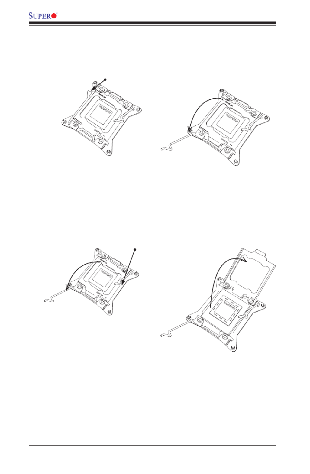
Installing the LGA2011 Processor
1. There are two load levers on the LGA2011 socket. To open the socket cover,
rst press and release the load lever labeled 'Open 1st'.
OPEN 1st
WARNING!
12
2-6
X9DRT-HF/HIBQF/HIBFF Motherboard User’s Manual
OPEN 1st
WARNING!
2. Press the second load lever labeled 'Close 1st' to release the load plate that
covers the CPU socket from its locking position.
3. With the 'Close 1st' lever fully retracted, gently push down on the 'Open 1st'
lever to open the load plate. Lift the load plate to open it completely.
OPEN 1st
WARNING!
OPEN 1st
WARNING!
12
Press down on
Load
Lever 'Close 1st'
WARNING!
1
Pull lever away from
the socket
2
Gently push
down to pop the
load plate open.

Chapter 2: Installation
2-7
WARNING!
1. Using your thumb and the index nger, remove the 'WARNING' plastic cap
from the socket.
2. Use your thumb and index nger to hold the CPU on its edges. Align the CPU
keys, which are semi-circle cutouts, against the socket keys.
3. Once they are aligned, carefully lower the CPU straight down into the socket.
(Do not drop the CPU on the socket. Do not move the CPU horizontally or
vertically. Do not rub the CPU against the surface or against any pins of the
socket to avoid damaging the CPU or the socket.)
Socket Keys
CPU Keys
Warning: You can only install the
CPU inside the socket in one direc-
tion. Make sure that it is properly
inserted into the CPU socket before
closing the load plate. If it doesn't
close properly, do not force it as it
may damage your CPU. Instead,
open the load plate again and dou-
ble-check that the CPU is aligned
properly.

2-8
X9DRT-HF/HIBQF/HIBFF Motherboard User’s Manual
4. With the CPU inside the socket, inspect the four corners of the CPU to make
sure that the CPU is properly installed.
5. Close the load plate with the CPU inside the socket. Lock the 'Close 1st' lever
rst, then lock the 'Open 1st' lever second. Use your thumb to gently push the
load levers down to the lever locks.
OPEN 1st
OPEN 1st
OPEN 1st
Lever Lock
Lever Lock
Push down and
lock 'Open 1st'
lever
Push down and lock
'Close 1st' lever.
Gently close
the load plate.
1 2
34

Chapter 2: Installation
2-9
Notes: 1. For optimized airow, please follow your chassis airow direc-
tion to install the correct CPU heatsink direction. 2. Graphic drawings
included in this manual are for reference only. They might look different
from the components installed in your system.
Installing a Passive CPU Heatsink
1. Apply the proper amount of thermal grease to the heatsink.
2. Place the heatsink on top of the CPU so that the two mounting holes on the
heatsink are aligned with those on the retention mechanism.
3. Insert two push-pins on the sides of the heatsink through the mounting holes
on the motherboard, and turn the push-pins clockwise to lock them.
Screw#1
Screw#2
Screw#3
Screw#4
OP EN 1s t

2-10
X9DRT-HF/HIBQF/HIBFF Motherboard User’s Manual
Removing the Passive Heatsink
Warning: We do not recommend that the CPU or the heatsink be removed. However,
if you do need to remove the heatsink, please follow the instructions below to uninstall
the heatsink to avoid damaging the CPU or other components.
1. Unplug the power cord from the power supply.
2. Press down the push-pin on the heatsink, and turn counter-clock-wise to
loosen it. Repeat the same step to loosen the second push-pin.
3. Hold the heatsink as shown in the picture below, and wriggle the heatgently -
sink to loosen it. (Do not use excessive force when wriggling the heatsink.)
4. Once the heatsink is loosened, remove it from the motherboard.
OP EN 1s t

Chapter 2: Installation
2-11
JF2
JSD1
SW1
JIPMB1
J21
JBT1
LEB1LEB2
LE3
JI2C2
JI2C1
JNMI1
JRST1
JWD1
JPME2
JIB1
JWP1
JPL1
JPG1
JBAT1
JTPM1
P2 DIMMF1P2 DIMME1
XDP-CPU
COM1
VGA
S-SATA0
Always DIMMxA First
CPU1_Port2 SXB1 PCI-E 3.0 x16
LAN1
IPMI_LAN
USB0/1
LAN2
USB2
P1 DIMMC1
UID
P1 DIMMD1
X9DRT-HF
Rev. 1.21
BIOS
P1 DIMMB1 FP CTRL PWR SPPLY
PCH
IB CTRL
InfiniBand
Connector
LAN CTRL
BMC
PCI-Ex16 (Proprie tary)
P2 DIMMH1
J4
LE1
LE2
JPB1
JB2
JB3
JB1
LEM1
S-SATA2
I-SATA1
I-SATA0
P1 DIMMA1
JPME1
CPU1_Port3A SXB2
PCI-E 3.0 X8CPU2_Port2C SXB3
PCI-E 3.0 X8
S-SATA3
CLOSE 1s t
OPEN 1st
CPU2
P2 DIMMG1
CPU1
CLOSE 1s t
OPEN 1st
Release Tabs
Notches
2-4 Installing and Removing the Memory Modules
Note: Check Supermicro's website for recommended memory modules.
CAUTION
Exercise extreme care when installing or removing DIMM
modules to prevent any possible damage.
Installing & Removing DIMMs
1. Insert the desired number of DIMMs into the memory slots, starting with
P1-DIMMA1. (For best performance, please use the memory modules of the
same type and speed in the same bank.)
2. Push the release tabs outwards on both ends of the DIMM slot to unlock it.
Removing Memory Modules
Press the release tabs on both ends of the memory module to unlock it. Once it is
loosened, remove the DIMM module from the memory slot.
3. Align the key of the DIMM module with the receptive point on the memory
slot.
4. Align the notches on both ends of the module against the receptive points on
the ends of the slot.
5. Use two thumbs together to press the notches on both ends of the module
straight down into the slot until the module snaps into place.
6. Press the release tabs to the locking positions to secure the DIMM module
into the slot.
Press both notches straight
down into the memory slot at
the same time.
2-12
X9DRT-HF/HIBQF/HIBFF Motherboard User’s Manual
Notes: 1866 MHz memory speed is dependent on Intel E5-2600v2 CPUs.
For Intel E5-2600(v2) processor support, BIOS version 3.0 or above is
required.
Memory Support for the X9DRT-HF/HIBQF/HIBFF Motherboard
The X9DRT-HF/HIBQF/HIBFF motherboard supports up to 512 GB of Load Re-
duced (LRDIMM), 256 GB of Registered (RDIMM) or 64 GB of Unbuffered (UDIMM)
ECC/Non-ECC DDR3 800/1066/1333/1600/1866 MHz 240-pin 4-channel memory
modules in eight DIMM slots.
Note: For the latest memory updates, please refer to the Tested Memory
List posted on our website (http://www.supermicro.com/products/mother-
board).
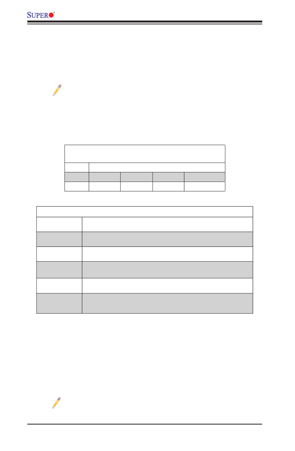
Processor & Memory Module Population Conguration
For memory to work properly, follow the tables below for memory installation.
Processors and their Corresponding Memory
Modules
CPU# Corresponding DIMM Modules
CPU 1 P1-DIMMA1 P1-DIMMB1 P1-DIMMC1 P1-DIMMD1
CPU2 P2-DIMME1 P2-DIMMF1 P2-DIMMG1 P2-DIMMH1
Processor and Memory Module Population
Number of
CPUs+DIMMs
CPUandMemoryPopulationCongurationTable
(*For memory to work proper, please install DIMMs in pairs)
1 CPU &
2 DIMMs
CPU1
P1-DIMMA1/P1-DIMMB1
1 CPU &
4 DIMMs
CPU1
P1-DIMMA1/P1-DIMMB1, P1-DIMMC1/P1-DIMMD1
2 CPUs &
4 DIMMs
CPU1 + CPU2
P1-DIMMA1/P1-DIMMB1, P2-DIMME1/P2-DIMMF1
2 CPUs &
6 DIMMs
CPU1 + CPU2
P1-DIMMA1/P1-DIMMB1, P2-DIMME1/P2-DIMMF1, P1-DIMMC1/P1-DIMMD1
2 CPUs &
8 DIMMs
CPU1/CPU
P1-DIMMA1/P1-DIMMB1, P2-DIMME1/P2-DIMMF1, P1-DIMMC1/P1-DIMMD1,
P2-DIMMG1/P2-DIMMH1

Chapter 2: Installation
2-13
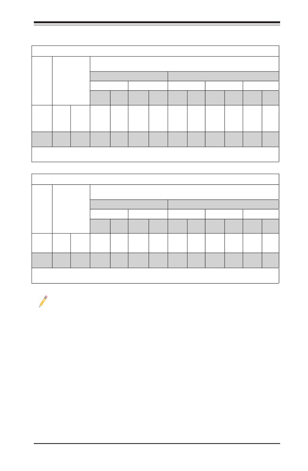
Populating UDIMM (ECC/Non-ECC) Memory Modules
Intel E5-2600(v2) Series Processor UDIMM Memory Support
Ranks
Per
DIMM
& Data
Width
Memory Capacity
Per DIMM
(See the Note below)
Speed (MT/s) and Voltage Validated by Slot per Channel (SPC) and
DIMM Per Channel (DPC)
2 Slots Per Channel 3 Slots Per Channel
1DPC 2DPC 1DPC 2DPC
1.35V 1.5V 1.35V 1.5V 1.35V 1.5V 1.35V 1.5v
SRx8
Non-
ECC
1GB 2GB 4GB NA 1066,
1333,
1600,
1866
NA 1066,
1333,
1600
N/A 1066,
1333,
1600,
1866
N/A 1066,
1333,
1600
DRx8
Non-
ECC
2GB 4GB 8GB NA 1066,
1333,
1600,
1866
NA 1066,
1333,
1600
N/A 1066,
1333,
1600,
1866
N/A 1066,
1333,
1600
SRx16
Non-
ECC
512MB 1GB 2GB NA 1066,
1333,
1600,
1866
NA 1066,
1333,
1600
N/A 1066,
1333,
1600,
1866
N/A 1066,
1333,
1600
SRx8
ECC
1GB 2GB 4GB 1066,
1333
1066,
1333,
1600,
1866
1066,
1333
1066,
1333,
1600
1066,
1333
1066,
1333,
1600,
1866
1066,
1333
1066,
1333,
1600
DRx8
ECC
2GB 4GB 8GB 1066,
1333
1066,
1333,
1600,
1866
1066,
1333
1066,
1333,
1600
1066,
1333
1066,
1333,
1600,
1866
1066,
1333
1066,
1333,
1600
Note: For detailed information on memory support and updates, please refer to the SMC Recommended
Memory List posted on our website at http://www.supermicro.com/support/resources/mem.cfm.
Populating RDIMM (ECC) Memory Modules
Intel E5-2600(v2) Series Processor RDIMM Memory Support
Ranks
Per
DIMM
&
Data
Width
Memory Capacity
Per DIMM
(See the Note Below)
Speed (MT/s) and Voltage Validated by Slot per Channel (SPC) and DIMM Per Channel
(DPC)
2 Slots Per Channel 3 Slots Per Channel
1DPC 2DPC 1 DPC 2DPC 3DPC
1.35V 1.5V 1.35V 1.5V 1.35V 1.5V 1.35V 1.5V 1.35V 1.5v
SRx8 1GB 2GB 4GB 1066,
1333
1066,
1333,
1600,
1866
1066,
1333
1066,
1333,
1600
1066,
1333
1066,
1333,
1600,
1866
1066,
1333
1066,
1333,
1600
800 800,
1066
DRx8 2GB 4GB 8GB 1066,
1333
1066,
1333,
1600,
1866
1066,
1333
1066,
1333,
1600
1066,
1333
1066,
1333,
1600,
1866
1066,
1333
1066,
1333,
1600
800 800,
1066
SRx4 2GB 4GB 8GB 1066,
1333
1066,
1333,
1600,
1866
1066,
1333
1066,
1333,
1600
1066,
1333
1066,
1333,
1600,
1866
1066,
1333
1066,
1333,
1600
800 800,
1066
DRx4 4GB 8GB 16GB 1066,
1333
1066,
1333,
1600,
1866
1066,
1333
1066,
1333,
1600
1066,
1333
1066,
1333,
1600,
1866
1066,
1333
1066,
1333,
1600
800 800,
1066
QRx4 8GB 16GB 32GB 800 800
1066
800 800 800 800,
1066
800 800 N/A N/A
QRx8 4GB 8GB 16GB 800 800
1066
800 800 800 800,
1066
800 800 N/A N/A
Note: For detailed information on memory support and updates, please refer to the SMC Recommended Memory List posted on
our website at http://www.supermicro.com/support/resources/mem.cfm.

2-14
X9DRT-HF/HIBQF/HIBFF Motherboard User’s Manual
Populating UDIMM (ECC/Non-ECC) Memory Modules
Intel E5-2600 Series Processor UDIMM Memory Support
Ranks
Per
DIMM
& Data
Width
Memory Capacity
Per DIMM
(See the Note below)
Speed (MT/s) and Voltage Validated by Slot per Channel (SPC) and
DIMM Per Channel (DPC)
2 Slots Per Channel 3 Slots Per Channel
1DPC 2DPC 1DPC 2DPC
1.35V 1.5V 1.35V 1.5V 1.35V 1.5V 1.35V 1.5v
SRx8
Non-
ECC
1GB 2GB 4GB NA 1066,
1333
NA 1066,
1333
N/A 1066,
1333,
N/A 1066,
1333
DRx8
Non-
ECC
2GB 4GB 8GB NA 1066,
1333
NA 1066,
1333
N/A 1066,
1333,
N/A 1066,
1333
SRx16
Non-
ECC
512MB 1GB 2GB NA 1066,
1333
NA 1066,
1333
N/A 1066,
1333
N/A 1066,
1333
SRx8
ECC
1GB 2GB 4GB 1066,
1333
1066,
1333
1066 1066,
1333
1066 1066,
1333,
1066,
1333
1066,
1333
DRx8
ECC
2GB 4GB 8GB 1066,
1333
1066,
1333
1066 1066,
1333
1066 1066,
1333,
1066,
1333
1066,
1333
Note: For detailed information on memory support and updates, please refer to the SMC Recommended
Memory List posted on our website at http://www.supermicro.com/support/resources/mem.cfm.
Populating RDIMM (ECC) Memory Modules
Intel E5-2600 Series Processor RDIMM Memory Support
Ranks
Per
DIMM
&
Data
Width
Memory Capacity
Per DIMM
(See the Note Below)
Speed (MT/s) and Voltage Validated by Slot per Channel (SPC) and DIMM Per Channel
(DPC)
2 Slots Per Channel 3 Slots Per Channel
1DPC 2DPC 1 DPC 2DPC 3DPC
1.35V 1.5V 1.35V 1.5V 1.35V 1.5V 1.35V 1.5V 1.35V 1.5v
SRx8 1GB 2GB 4GB 1066,
1333
1066,
1333,
1600
1066,
1333
1066,
1333,
1600
1066,
1333
1066,
1333,
1600
1066,
1333
1066,
1333,
1600
N/A 800,
1066
DRx8 2GB 4GB 8GB 1066,
1333
1066,
1333,
1600
1066,
1333
1066,
1333,
1600
1066,
1333
1066,
1333,
1600
1066,
1333
1066,
1333,
1600
N/A 800,
1066
SRx4 2GB 4GB 8GB 1066,
1333
1066,
1333,
1600
1066,
1333
1066,
1333,
1600
1066,
1333
1066,
1333,
1600
1066,
1333
1066,
1333,
1600
N/A 800,
1066
DRx4 4GB 8GB 16GB 1066,
1333
1066,
1333,
1600
1066,
1333
1066,
1333,
1600
1066,
1333
1066,
1333,
1600
1066,
1333
1066,
1333,
1600
N/A 800,
1066
QRx4 8GB 16GB 32GB 800 1066 800 800 800 1066 800 800 N/A N/A
QRx8 4GB 8GB 16GB 800 1066 800 800 800 1066 800 800 N/A N/A
Note: For detailed information on memory support and updates, please refer to the SMC Recommended Memory List posted on
our website at http://www.supermicro.com/support/resources/mem.cfm.
Chapter 2: Installation
2-15
Populating LRDIMM (ECC) Memory Modules
Intel E5-2600(v2) Series Processor LRDIMM Memory Support
Ranks
Per
DIMM
&
Data
Width
Memory
Capacity
Per DIMM
(See the Note
Below)
Speed (MT/s) and Voltage Validated by Slot per Channel (SPC) and DIMM Per
Channel (DPC)
2 Slots Per Channel 3 Slots Per Channel
1DPC 2DPC 1DPC 2DPC 3DPC
1.35V 1.5V 1.35V 1.5V 1.35V 1.5V 1.35V 1.5V 1.35V 1.5V
QRx4
(DDP)
16GB 32GB 1066,
1333,
1600
1066,
1333,
1600,
1866
1066,
1333,
1600
1066,
1333,
1600
1066,
1333,
1600
1066,
1333,
1600,
1866
1066,
1333,
1600
1066,
1333,
1600
1066 1066
8Rx4
(QDP)
32GB 64GB 1066 1066 1066 1066 1066 1066 1066 1066 1066 1066
Note: For detailed information on memory support and updates, please refer to the SMC Recommended Memory
List posted on our website at http://www.supermicro.com/support/resources/mem.cfm.
Intel E5-2600 Series Processor LRDIMM Memory Support
Ranks
Per
DIMM
&
Data
Width
Memory
Capacity
Per DIMM
(See the Note
Below)
Speed (MT/s) and Voltage Validated by Slot per Channel (SPC) and DIMM Per
Channel (DPC)
2 Slots Per Channel 3 Slots Per Channel
1DPC 2DPC 1DPC 2DPC 3DPC
1.35V 1.5V 1.35V 1.5V 1.35V 1.5V 1.35V 1.5V 1.35V 1.5V
QRx4
(DDP)
16GB 32GB 1066 1066,
1333
1066 1066,
1333
1066 1066,
1333
1066 1066,
1333
1066 1066
QRx8
(QDP)
8GB 16GB 1066 1066,
1333
1066 1066,
1333
1066 1066 1066 1066 1066 1066
Note: For detailed information on memory support and updates, please refer to the SMC Recommended Memory
List posted on our website at http://www.supermicro.com/support/resources/mem.cfm.
Other Important Notes and Restrictions
• For the memory modules to work properly, please install DIMM modules of the same
type, same speed and same operating frequency on the motherboard. Mixing of
RDIMMs, UDIMMs or LRDIMMs is not allowed. Do not install both ECC and Non-ECC
memory modules on the same motherboard.
• Using DDR3 DIMMs with different operating frequencies is not allowed. All channels
in a system will run at the lowest common frequency.

2-16
X9DRT-HF/HIBQF/HIBFF Motherboard User’s Manual
JF2
JSD1
SW1
JIPMB1
J21
JBT1
EB1
LEB2
LE3
JI2C2
JI2C1
JNMI1
JRST1
JWD1
JPME2
JIB1
JWP1
JPL1
JPG1
JBAT1
JTPM1
P2 DIMMF1
P2 DIMME1
XDP-CPU
S-SATA0
Always DIMMxA First
CPU1_Port2 SXB1 PCI-E 3.0 x16
LAN1
IPMI_LAN
USB0/1
LAN2
USB2
P1 DIMMC1
UID
P1 DIMMD1
X9DRT-HF
Rev. 1.21
BIOS
P1 DIMMB1 FP CTRL PWR SPPLY
PCH
IB CTRL
InfiniBand
Connector
LAN CTRL
BMC
PCI-Ex16 (Proprietary)
P2 DIMMH1
J4
LE1
2
JPB1
JB2
JB3
JB1
LEM1
S-SATA2
I-SATA1
I-SATA0
P1 DIMMA1
JPME1
CPU1_Port3A SXB2
PCI-E 3.0 X8
CPU2_Port2C SXB3
PCI-E 3.0 X8
S-SATA3
CLOS E 1st
OPEN 1st
CPU2
P2 DIMMG1
CPU1
CLOS E 1st
OPEN 1st
2-5 Motherboard Installation
All motherboards have standard mounting holes to t different types of chassis.
Make sure that the locations of all the mounting holes for both motherboard and
chassis match. Although a chassis may have both plastic and metal mounting fas-
teners, metal ones are highly recommended because they ground the motherboard
to the chassis. Make sure that the metal standoffs click in or are screwed in tightly.
Then use a screwdriver to secure the motherboard onto the motherboard tray.
Tools Needed
• Philips Screwdriver
• Pan head screws (9 pieces)
• Standoffs (9 pieces, if needed)
Location of Mounting Holes
There are nine (9) mounting holes on this motherboard indicated by the arrows.
Caution: 1) To avoid damaging the motherboard and its components,
please do not use a force greater than 8 lb/inch on each mounting screw
during motherboard installation. 2) Some components are very close to
the mounting holes. Please take precautionary measures to prevent dam-
age to these components when installing the motherboard to the chassis.

Chapter 2: Installation
2-17
Installing the Motherboard
1. Install the I/O shield into the chassis.
2. Locate the mounting holes on the motherboard.
3. Locate the matching mounting holes on the chassis. Align the mounting holes
on the motherboard against the mounting holes on the chassis.
4. Install standoffs in the chassis as needed.
5. Install the motherboard into the chassis carefully to avoid damaging mother-
board components.
6. Using the Phillips screwdriver, insert a Pan head #6 screw into a mounting
hole on the motherboard and its matching mounting hole on the chassis.
7. Repeat Step 5 to insert #6 screws into all mounting holes.
8. Make sure that the motherboard is securely placed in the chassis.
Note: Images displayed are for illustration only. Your chassis or compo-
nents might look different from those shown in this manual.

2-18
X9DRT-HF/HIBQF/HIBFF Motherboard User’s Manual
JF2
JSD1
SW1
JIPMB1
J21
JBT1
LEB1
LEB2
LE3
JI2C2
JI2C1
JNMI1
JRST1JWD1
JPME2
JIB1
JWP1
JPL1
JPG1
JBAT1
JTPM1
P2 DIMMF1P2 DIMME1
XDP-CPU
COM1
VGA
S-SATA0
Always DIMMxA First
CPU1_Port2 SXB1 PCI-E 3.0 x16
LAN1
IPMI_LAN
USB0/1
LAN2
USB2
P1 DIMMC1
UID
P1 DIMMD1
X9DRT-HF
Rev. 1.21
BIOS
P1 DIMMB1 FP CTRL PWR SPPLY
PCH
IB CTRL
InfiniBand
Connector
LAN CTRL
BMC
PCI-Ex16 (Proprietary)
P2 DIMMH1
J4
LE1
LE2
JPB1
JB2
JB3
JB1
LEM1
S-SATA2
I-SAT A1
I-SAT A0
P1 DIMMA1
JPME1
CPU1_Port3A S XB2
PCI-E 3.0 X8
CPU2_Port2C SX B3
PCI-E 3.0 X8
S-SATA3
CLOSE 1st
OPEN 1 st
CPU2
P2 DIMMG1
CPU1
CLOSE 1st
OPEN 1 st
2-6 Control Panel Connectors and I/O Ports
The I/O ports are color coded in conformance with the PC 99 specication. See
the picture below for the colors and locations of the various I/O ports.
Back Panel Connectors and I/O Ports
BackPanelI/OPort Locationsand Denitions
1. Back Panel USB Port 0
2. Back Panel USB Port 1
3. IPMI_Dedicated LAN
4. Gigabit LAN 1
5. Gigabit LAN 2
6. COM Port 1 (Turquoise)
7. Back Panel VGA (Blue)
8. InniBand Connector (For X9DRT-
HIBQF/HIBFF)
9. UID Switch
1
2
3
4
5
6
7
8
9

Chapter 2: Installation
2-19
JF2
JSD1
SW1
JIPMB1
J21
JBT1
LEB1
LEB2
LE3
JI2C2
JI2C1
JNMI1
JRST1
JWD1
JPME2
JIB1
JWP1
JPL1
JPG1
JBAT1
JTPM1
P2 DIMMF1
P2 DIMME1
XDP-CPU
COM1
VGA
S-SATA0
Always DIMMxA First
CPU1_Port2 SXB1 PCI-E 3.0 x16
LAN1
IPMI_LAN
USB0/1
LAN2
USB2
P1 DIMMC1
UID
P1 DIMMD1
X9DRT-HF
Rev. 1.21
BIOS
P1 DIMMB1 FP CTRL PWR SPPLY
PCH
IB CTRL
InfiniBand
Connector
LAN CTRL
BMC
PCI-Ex16 (Proprietary)
P2 DIMMH1
J4
LE1
LE2
JPB1
JB2
JB3
JB1
LEM1
S-SATA2
I-SATA1
I-SATA0
P1 DIMMA1
JPME1
CPU1_Port3A SXB2
PCI-E 3.0 X8
CPU2_Port2C SXB3
PCI-E 3.0 X8
S-SATA3
CLOSE 1st
OPEN 1st
CPU2
P2 DIMMG1
CPU1
CLOSE 1st
OPEN 1st
Universal Serial Bus (USB)
Two Universal Serial Bus ports (USB
0/1) are located on the I/O back panel.
In addition, a USB header, located
close to the BMC chip, provides front-
accessible USB connection (USB 2).
(Cables are not included.) See the
tables on the right for pin denitions.
Backplane USB
(USB 0/1)
PinDenitions
Pin# Denition
1 +5V
2 PO-
3 PO+
4 Ground
5 NA
1. USB 0
2. USB 1
3. USB 2
1
2
3
Front Access-
ible USB (USB
2)
PinDenitions
Pin# Denition
1 +5V
2 PO-
3 PO+
4 Ground
5 NA

2-20
X9DRT-HF/HIBQF/HIBFF Motherboard User’s Manual
JF2
JSD1
SW1
JIPMB1
J21
JBT1
LEB1
LEB2
LE3
JI2C2
JI2C1
JNMI1
JRST1
JWD1
JPME2
JIB1
JWP1
JPL1
JPG1
JBAT1
JTPM1
P2 DIMMF1
P2 DIMME1
XDP-CPU
COM1
VGA
S-SATA0
Always DIMMxA First
CPU1_Port2 SXB1 PCI-E 3.0 x16
LAN1
IPMI_LAN
USB0/1
LAN2
USB2
P1 DIMMC1
UID
P1 DIMMD1
X9DRT-HF
Rev. 1.21
BIOS
P1 DIMMB1 FP CTRL PWR SPPLY
PCH
IB CTRL
InfiniBand
Connector
LAN CTRL
BMC
PCI-Ex16 (Proprietary)
P2 DIMMH1
J4
LE1
LE2
JPB1
JB2
JB3
JB1
LEM1
S-SATA2
I-SATA1
I-SATA0
P1 DIMMA1
JPME1
CPU1_Port3A SXB2
PCI-E 3.0 X8
CPU2_Port2C SXB3
PCI-E 3.0 X8
S-SATA3
CLOSE 1st
OPEN 1st
CPU2
P2 DIMMG1
CPU1
CLOSE 1st
OPEN 1st
1. LAN 1
2. LAN 2
3. IPMI_LAN
1
2
3
Ethernet Ports
Two Gigabit Ethernet ports (LAN1/2)
are located on the I/O backplane on
the motherboard. In addition, an IPMI_
Dedicated LAN is located above USB
0/1 ports on the backplane to provide
KVM support for IPMI 2.0. All these
ports accept RJ45 type cables. (Note:
Please refer to the LED Indicator Sec-
tion for LAN LED information.)
LAN Ports
PinDenition
Pin# Denition
1 P2V5SB 10 SGND
2 TD0+ Act LED11
3 TD0- 12 P3V3SB
4 TD1+ 13 Link 100 LED (Yel-
low, +3V3SB)
5 TD1- 14 Link 1000 LED
(Yellow, +3V3SB)
6 TD2+ 15 Ground
7 TD2- 16 Ground
8 TD3+ 17 Ground
9 TD3- 18 Ground
(NC: No Connection)

Chapter 2: Installation
2-21
JF2
JSD1
SW1
JIPMB1
J21
JBT1
LEB1
LEB2
LE3
JI2C2
JI2C1
JNMI1
JRST1
JWD1
JPME2
JIB1
JWP1
JPL1
JPG1
JBAT1
JTPM1
P2 DIMMF1
P2 DIMME1
XDP-CPU
COM1
VGA
S-SATA0
Always DIMMxA First
CPU1_Port2 SXB1 PCI-E 3.0 x16
LAN1
IPMI_LAN
USB0/1
LAN2
USB2
P1 DIMMC1
UID
P1 DIMMD1
X9DRT-HF
Rev. 1.21
BIOS
P1 DIMMB1 FP CTRL PWR SPPLY
PCH
IB CTRL
InfiniBand
Connector
LAN CTRL
BMC
PCI-Ex16 (Proprietary)
P2 DIMMH1
J4
LE1
LE2
JPB1
JB2
JB3
JB1
LEM1
S-SATA2
I-SATA1
I-SATA0
P1 DIMMA1
JPME1
CPU1_Port3A SXB2
PCI-E 3.0 X8
CPU2_Port2C SXB3
PCI-E 3.0 X8
S-SATA3
CLOSE 1st
OPEN 1st
CPU2
P2 DIMMG1
CPU1
CLOSE 1st
OPEN 1st
1
2
Serial Ports
A COM Port is located on the IO
Backplane. See the table on the right
for pin denitions.
SerialPortPinDenitions
(COM1)
Pin # Denition Pin # Denition
1 CDC 6 DSR
2 RXD 7 RTS
3 TXD 8 CTS
4 DTR 9 RI
5 Ground
Video Connector
A Video (VGA) connector is located
next to the COM Port on the IO
backplane. This connector is used
to provide video and CRT display.
Refer to the board layout below for
the location.
1. COM Port
2. VGA Port

2-22
X9DRT-HF/HIBQF/HIBFF Motherboard User’s Manual
JF2
JSD1
SW1
JIPMB1
J21
JBT1
LEB1
LEB2
LE3
JI2C2
JI2C1
JNMI1
JRST1
JWD1
JPME2
JIB1
JWP1
JPL1
JPG1
JBAT1
JTPM1
P2 DIMMF1
P2 DIMME1
XDP-CPU
COM1
VGA
S-SATA0
Always DIMMxA First
CPU1_Port2 SXB1 PCI-E 3.0 x16
LAN1
IPMI_LAN
USB0/1
LAN2
USB2
P1 DIMMC1
UID
P1 DIMMD1
X9DRT-HF
Rev. 1.21
BIOS
P1 DIMMB1 FP CTRL PWR SPPLY
PCH
IB CTRL
InfiniBand
Connector
LAN CTRL
BMC
PCI-Ex16 (Proprietary)
P2 DIMMH1
J4
LE1
LE2
JPB1
JB2
JB3
JB1
LEM1
S-SATA2
I-SATA1
I-SATA0
P1 DIMMA1
JPME1
CPU1_Port3A SXB2
PCI-E 3.0 X8
CPU2_Port2C SXB3
PCI-E 3.0 X8
S-SATA3
CLOSE 1st
OPEN 1st
CPU2
P2 DIMMG1
CPU1
CLOSE 1st
OPEN 1st
InniBandConnection(ForX9DRT-HIBQF/HIBFF)
The onboard InniBand (IB) connector is located on the backplane on the
motherboard. The IB switch is primarily used for High-performance computing.
See the table below for pin denitions.
1. InniBand
1
Pin
Description
1
Ground
2
Transmitter Inverted Data
I tnpu
3
Transmitter
Non-Inverted
Data
Input
4
Ground
5 ed Dat Transmitter Invert a
I tnpu
6
Transmitter
Non-Inverted
Data
Input
7
Ground
8
Module
Select
9
Module
Reset
10
+3.3 V Power supp ly
receiver
11
2-wire serial interface
cl koc
12
2-wire serial interface
data
13
Ground
14
Receiver
Non-Invert ed
Data
Output
15
Receiver Inverted Data
Output
16
Ground
17
Receiver
Non-Invert ed
Data
Output
18
Receiver Data Inverted
Output
19
Ground
20
Ground
21
Receiver Data Inverted
Output
22
Receiver
Non-Invert ed
Data
Output
23
Ground
24
Receiver Data Inverted
Output
25
Receiver
Non-Inverted
Data
Output
26
Ground
27
Module
Pr tesen
28
Interrupt
29
+3.3 V Power supp ly
tr teansmit r
30
+3.3 V Power
Supply
31
Low Power
Mode
32
Ground
33
Transmitter
Non-Inverted
Data
Inp
u
t
34
Transm Invertitter ed Data
I tnpu
35
Ground
36
Transmitter
Non-Inverted
Data
Inp
u
t
37
Transm Invertitter ed Data
I tnpu
38
Ground

Chapter 2: Installation
2-23
JF2
JSD1
SW1
JIPMB1
J21
JBT1
LEB1
LEB2
LE3
JI2C2
JI2C1
JNMI1
JRST1
JWD1
JPME2
JIB1
JWP1
JPL1
JPG1
JBAT1
JTPM1
P2 DIMMF1
P2 DIMME1
XDP-CPU
COM1
VGA
S-SATA0
Always DIMMxA First
CPU1_Port2 SXB1 PCI-E 3.0 x16
LAN1
IPMI_LAN
USB0/1
LAN2
USB2
P1 DIMMC1
UID
P1 DIMMD1
X9DRT-HF
Rev. 1.21
BIOS
P1 DIMMB1 FP CTRL PWR SPPLY
PCH
IB CTRL
InfiniBand
Connector
LAN CTRL
BMC
PCI-Ex16 (Proprietary)
P2 DIMMH1
J4
LE1
LE2
JPB1
JB2
JB3
JB1
LEM1
S-SATA2
I-SATA1
I-SATA0
P1 DIMMA1
JPME1
CPU1_Port3A SXB2
PCI-E 3.0 X8
CPU2_Port2C SXB3
PCI-E 3.0 X8
S-SATA3
CLOSE 1st
OPEN 1st
CPU2
P2 DIMMG1
CPU1
CLOSE 1st
OPEN 1st
1
2
UnitIdentierSwitches
Two Unit Identier (UID) Switches and two LED
Indicators are located on the motherboard. The
Front Panel UID Switch is located at pin 16 on JF2.
The Rear UID Switch is located at SW1 next to the
InniBand Connector. The Front Panel UID LED is
located at pin 17 of JF2, and the Rear UID LED is
located at LE2. When the user presses a UID switch
on the front panel or on the back panel, both Rear
UID LED and Front Panel UID LED Indicators will be
turned on. Press the UID switch again to turn off both
LED Indicators. These UID Indicators provide easy
identication of a system unit that may be in need of
service. See the table on the right for pin denitions.
Note: UID LED is supported by the physical
switch or the BMC. When it is controlled by
the physical switch, it will stay solid. When it
is controlled by the BMC, it will blink.
UID Switch
Pin# Denition
1 Ground
2 Ground
3 Button In
4 Ground
UID Switches & LEDs
Description Location
FP Switch Pin 16 on JF2
Rear Switch SW1
FP UID LED
(Blue LED)
Pin 17 on JF2
Rear UID LED LE2
1. Rear UID Switch
2. FP UID Switch & FP UID LED
3. Rear UID Switch & Rear UID LED
3

2-24
X9DRT-HF/HIBQF/HIBFF Motherboard User’s Manual
Front Panel Accessible Add-on Card Header (JF2)
JF2 Add-on card header provides front access to the power supply, Serial ATA and
Front Panel Control connections for the X9DRT-HF Series motherboard. Insert an
Add-On card into this header to use the functions indicated above. This header
is designed specically for the Supermicro-proprietary add-on card (BPN-ADPX9-
6SATA3). Refer to the layout below for the location of JF2.
JF2
JSD1
SW1
JIPMB1
J21
JBT1
LEB1
LEB2
LE3
JI2C2
JI2C1
JNMI1
JRST1
JWD1
JPME2
JIB1
JWP1
JPL1
JPG1
JBAT1
JTPM1
P2 DIMMF1
P2 DIMME1
XDP-CPU
COM1
VGA
S-SATA0
Always DIMMxA First
CPU1_Port2 SXB1 PCI-E 3.0 x16
LAN1
IPMI_LAN
USB0/1
LAN2
USB2
P1 DIMMC1
UID
P1 DIMMD1
X9DRT-HF
Rev. 1.21
BIOS
P1 DIMMB1 FP CTRL PWR SPPLY
PCH
IB CTRL
InfiniBand
Connector
LAN CTRL
BMC
PCI-Ex16 (Proprietary)
P2 DIMMH1
J4
LE1
LE2
JPB1
JB2
JB3
JB1
LEM1
S-SATA2
I-SATA1
I-SATA0
P1 DIMMA1
JPME1
CPU1_Port3A SXB2
PCI-E 3.0 X8
CPU2_Port2C SXB3
PCI-E 3.0 X8
S-SATA3
CLOSE 1st
OPEN 1st
CPU2
P2 DIMMG1
CPU1
CLOSE 1st
OPEN 1st

Chapter 2: Installation
2-25
JF2
JSD1
SW1
JIPMB1
J21
JBT1
LEB1
LEB2
LE3
JI2C2
JI2C1
JNMI1
JRST1
JWD1
JPME2
JIB1
JWP1
JPL1
JPG1
JBAT1
JTPM1
P2 DIMMF1
P2 DIMME1
XDP-CPU
COM1
VGA
S-SATA0
Always DIMMxA First
CPU1_Port2 SXB1 PCI-E 3.0 x16
LAN1
IPMI_LAN
USB0/1
LAN2
USB2
P1 DIMMC1
UID
P1 DIMMD1
X9DRT-HF
Rev. 1.21
BIOS
P1 DIMMB1 FP CTRL PWR SPPLY
PCH
IB CTRL
InfiniBand
Connector
LAN CTRL
BMC
PCI-Ex16 (Proprietary)
P2 DIMMH1
J4
LE1
LE2
JPB1
JB2
JB3
JB1
LEM1
S-SATA2
I-SATA1
I-SATA0
P1 DIMMA1
JPME1
CPU1_Port3A SXB2
PCI-E 3.0 X8
CPU2_Port2C SXB3
PCI-E 3.0 X8
S-SATA3
CLOSE 1st
OPEN 1st
CPU2
P2 DIMMG1
CPU1
CLOSE 1st
OPEN 1st
2-7 Connecting Cables
A. NMI Header
B. IPMB
A
B
NMI Header
The non-maskable interrupt header is located
at JNMI1. Refer to the table on the right for
pin denitions.
NMI Button
PinDenitions
Pin# Denition
1 Control
2 Ground
IPMB I2C SMB
A System Management Bus header for the
IPMI slot is located at JIPMB1. Connect an
appropriate cable here to use the IPMB I 2C
connection on your system.
SMB Header
PinDenitions
Pin# Denition
1 Data
2 Ground
3 Clock
4 No Connection

2-26
X9DRT-HF/HIBQF/HIBFF Motherboard User’s Manual
JF2
JSD1
SW1
JIPMB1
J21
JBT1
LEB1
LEB2
LE3
JI2C2
JI2C1
JNMI1
JRST1
JWD1
JPME2
JIB1
JWP1
JPL1
JPG1
JBAT1
JTPM1
P2 DIMMF1
P2 DIMME1
XDP-CPU
COM1
VGA
S-SATA0
Always DIMMxA First
CPU1_Port2 SXB1 PCI-E 3.0 x16
LAN1
IPMI_LAN
USB0/1
LAN2
USB2
P1 DIMMC1
UID
P1 DIMMD1
X9DRT-HF
Rev. 1.21
BIOS
P1 DIMMB1 FP CTRL PWR SPPLY
PCH
IB CTRL
InfiniBand
Connector
LAN CTRL
BMC
PCI-Ex16 (Proprietary)
P2 DIMMH1
J4
LE1
LE2
JPB1
JB2
JB3
JB1
LEM1
S-SATA2
I-SATA1
I-SATA0
P1 DIMMA1
JPME1
CPU1_Port3A SXB2
PCI-E 3.0 X8
CPU2_Port2C SXB3
PCI-E 3.0 X8
S-SATA3
CLOSE 1st
OPEN 1st
CPU2
P2 DIMMG1
CPU1
CLOSE 1st
OPEN 1st
A. System Reset
B. DOM PWR Connector
A
B
System Reset
A System Reset header is located at
JRST1 on the motherboard. Connect a
cable to this header for system reset.
Refer to the layout below for the location.
System Reset
PinDenition
Pin Setting Denition
Pin 1 Signal
Pin 2 Ground
DOM Power Connector
A power connector for SATA DOM (Disk_
On_Module) devices is located at JSD1.
Connect an appropriate cable here to pro-
vide power for your SATA DOM devices.
DOM PWR
PinDenitions
Pin# Denition
1 +5V
2 Ground
3 Ground

Chapter 2: Installation
2-27
JF2
JSD1
SW1
JIPMB1
J21
JBT1
LEB1
LEB2
LE3
JI2C2
JI2C1
JNMI1
JRST1
JWD1
JPME2
JIB1
JWP1
JPL1
JPG1
JBAT1
JTPM1
P2 DIMMF1
P2 DIMME1
XDP-CPU
COM1
VGA
S-SATA0
Always DIMMxA First
CPU1_Port2 SXB1 PCI-E 3.0 x16
LAN1
IPMI_LAN
USB0/1
LAN2
USB2
P1 DIMMC1
UID
P1 DIMMD1
X9DRT-HF
Rev. 1.21
BIOS
P1 DIMMB1 FP CTRL PWR SPPLY
PCH
IB CTRL
InfiniBand
Connector
LAN CTRL
BMC
PCI-Ex16 (Proprietary)
P2 DIMMH1
J4
LE1
LE2
JPB1
JB2
JB3
JB1
LEM1
S-SATA2
I-SATA1
I-SATA0
P1 DIMMA1
JPME1
CPU1_Port3A SXB2
PCI-E 3.0 X8
CPU2_Port2C SXB3
PCI-E 3.0 X8
S-SATA3
CLOSE 1st
OPEN 1st
CPU2
P2 DIMMG1
CPU1
CLOSE 1st
OPEN 1st
A. SATA DOM PWR
B. TPM/Port80
A
TPM Header/Port 80
A Trusted Platform Module/Port 80 head-
er is located at JTPM1 to provide TPM
support and Port 80 connection. Use this
header to enhance system performance
and data security. See the table on the
right for pin denitions.
TPM/Port 80 Header
PinDenitions
Pin # Denition Pin # Denition
1 LCLK 2 GND
3 LFRAME# 4 <(KEY)>
5 LRESET# 6 +5V (X)
7 LAD 3 8 LAD 2
9 +3.3V 10 LAD1
11 LAD0 12 GND
13 14SMB_CLK4 SMB_DAT4
15 16 SERIRQ+3V_DUAL
17 GND 18 CLKRUN# (X)
19 LPCPD# 20 LDRQ# (X)
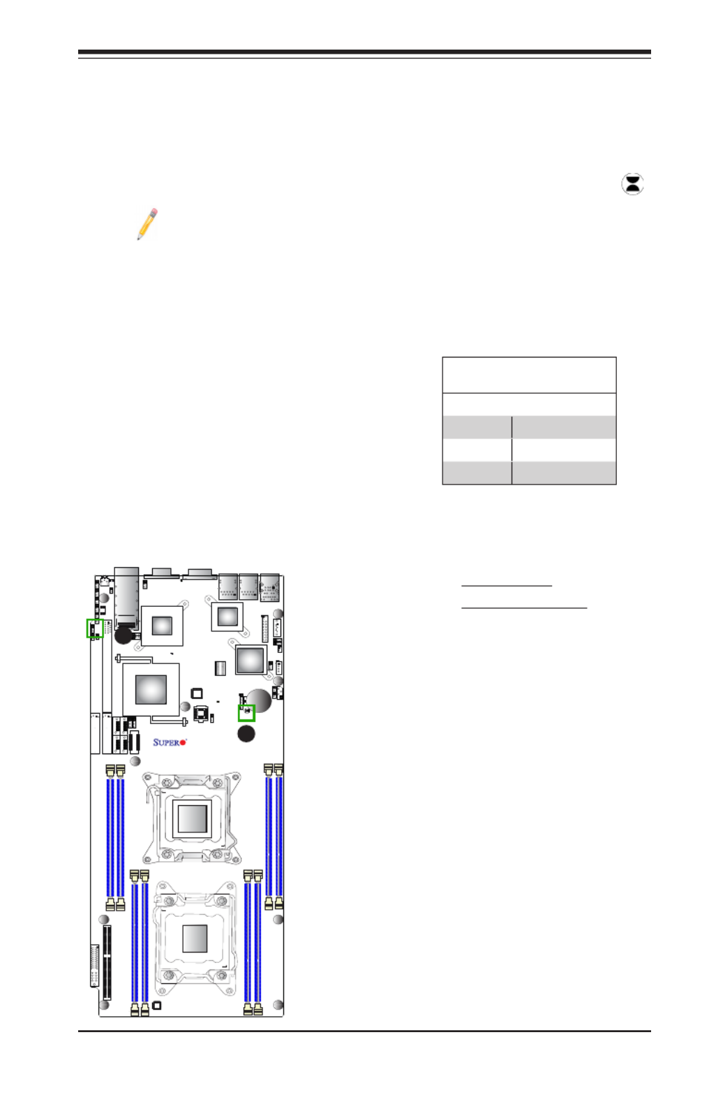
Chapter 2: Installation
2-29
JF2
JSD1
SW1
JIPMB1
J21
JBT1
LEB1
LEB2
LE3
JI2C2
JI2C1
JNMI1
JRST1
JWD1
JPME2
JIB1
JWP1
JPL1
JPG1
JBAT1
JTPM1
P2 DIMMF1
P2 DIMME1
XDP-CPU
COM1
VGA
S-SATA0
Always DIMMxA First
CPU1_Port2 SXB1 PCI-E 3.0 x16
LAN1
IPMI_LAN
USB0/1
LAN2
USB2
P1 DIMMC1
UID
P1 DIMMD1
X9DRT-HF
Rev. 1.21
BIOS
P1 DIMMB1 FP CTRL PWR SPPLY
PCH
IB CTRL
InfiniBand
Connector
LAN CTRL
BMC
PCI-Ex16 (Proprietary)
P2 DIMMH1
J4
LE1
LE2
JPB1
JB2
JB3
JB1
LEM1
S-SATA2
I-SATA1
I-SATA0
P1 DIMMA1
JPME1
CPU1_Port3A SXB2
PCI-E 3.0 X8
CPU2_Port2C SXB3
PCI-E 3.0 X8
S-SATA3
CLOS E 1st
OPEN 1st
CPU2
P2 DIMMG1
CPU1
CLOS E 1st
OPEN 1st
CMOS Clear
JBT1 is used to clear CMOS. Instead of pins, this "jumper" consists of contact pads
to prevent accidental clearing of CMOS. To clear CMOS, use a metal object such
as a small screwdriver to touch both pads at the same time to short the connection.
Always remove the AC power cord from the system before clearing CMOS.
Note 1: For an ATX power supply, you must completely shut down the
system, remove the AC power cord, and then short JBT1 to clear CMOS.
Note 2: Be sure to remove the onboard CMOS Battery before you short
JBT1 to clear CMOS.
Note 3: Clearing CMOS will also clear all passwords.
A. Clear CMOS
B. Watch Dog Enable
Watch Dog Enable/Disable
Watch Dog (JWD1) is a system monitor that
can reboot the system when a software ap-
plication hangs. Close pins 1-2 to reset the
system if an application hangs. Close pins
2-3 to generate non-maskable interrupt sig-
nals for the application that hangs. See the
table on the right for jumper settings. Watch
Dog must also be enabled in the BIOS.
Watch Dog
Jumper Settings
Jumper Setting Denition
Pins 1-2 Reset (default)
Pins 2-3 NMI
Open Disabled
A
B
Produktspecifikationer
| Varumärke: | Supermicro |
| Kategori: | moderkort |
| Modell: | X9DRT-HF |
Behöver du hjälp?
Om du behöver hjälp med Supermicro X9DRT-HF ställ en fråga nedan och andra användare kommer att svara dig
moderkort Supermicro Manualer

16 Februari 2025
15 Februari 2025
19 December 2024
5 December 2024
27 Oktober 2024
27 Oktober 2024
21 Oktober 2024
7 Oktober 2024
25 September 2024
24 September 2024
moderkort Manualer
- moderkort Asus
- moderkort Sharkoon
- moderkort Gigabyte
- moderkort Asrock
- moderkort Evga
- moderkort Intel
- moderkort MSI
- moderkort ECS
- moderkort NZXT
- moderkort Foxconn
- moderkort Advantech
- moderkort Elitegroup
- moderkort EPoX
- moderkort Biostar
Nyaste moderkort Manualer
8 April 2025
8 April 2025
3 April 2025
3 April 2025
3 April 2025
3 April 2025
2 April 2025
2 April 2025
1 April 2025
30 Mars 2025