ATen CS1798 Bruksanvisning
Läs nedan 📖 manual på svenska för ATen CS1798 (90 sidor) i kategorin Växla. Denna guide var användbar för 6 personer och betygsatt med 4.5 stjärnor i genomsnitt av 2 användare
Sida 1/90
8/16-port USB HDMI KVM Switch
CS1798 / CS17916
User Manual
www.aten.com

CS1798 / CS17916 User Manual
ii
EMC Information
FEDERAL COMMUNICATIONS COMMISSION INTERFERENCE
STATEMENT: This equipment has been tested and found to comply with the
limits for a Class A digital device, pursuant to Part 15 of the FCC Rules. These
limits are designed to provide reasonable protection against harmful
interference when the equipment is operated in a commercial environment.
This equipment generates, uses, and can radiate radio frequency energy and, if
not installed and used in accordance with the instruction manual, may cause
harmful interference to radio communications. Operation of this equipment in
a residential area is likely to cause harmful interference in which case the user
will be required to correct the interference at his own expense.
The device complies with Part 15 of the FCC Rules. Operation is subject to the
following two conditions: (1) this device may not cause harmful interference,
and (2) this device must accept any interference received, including
interference that may cause undesired operation.
FCC Caution: Any changes or modifications not expressly approved by the
party responsible for compliance could void the user's authority to operate this
equipment.
Warning: Operation of this equipment in a residential environment could
cause radio interference.
Achtung: Der Gebrauch dieses Geräts in Wohnumgebung kann
Funkstörungen verursachen.
KCC Statement
RoHS
This product is RoHS compliant.
© Copyright 2021 ATEN® International Co., Ltd.
Manual Date: 2021-01-04
ATEN and the ATEN logo are registered trademarks of ATEN International Co., Ltd. All rights reserved.
All other brand names and trademarks are the registered property of their respective owners. The
terms HDMI, HDMI High-Definition Multimedia Interface, and the HDMI Logo are trademarks or
registered trademarks of HDMI Licensing Administrator, Inc.

CS1798 / CS17916 User Manual
iii
User Information
Online Registration
Be sure to register your product at our online support center:
Telephone Support
For telephone support, call this number:
User Notice
All information, documentation, and specifications contained in this manual
are subject to change without prior notification by the manufacturer. The
manufacturer makes no representations or warranties, either expressed or
implied, with respect to the contents hereof and specifically disclaims any
warranties as to merchantability or fitness for any particular purpose. Any of
the manufacturer's software described in this manual is sold or licensed as is.
Should the programs prove defective following their purchase, the buyer (and
not the manufacturer, its distributor, or its dealer), assumes the entire cost of all
necessary servicing, repair and any incidental or consequential damages
resulting from any defect in the software.
The manufacturer of this system is not responsible for any radio and/or TV
interference caused by unauthorized modifications to this device. It is the
responsibility of the user to correct such interference.
The manufacturer is not responsible for any damage incurred in the operation
of this system if the correct operational voltage setting was not selected prior
to operation. PLEASE VERIFY THAT THE VOLTAGE SETTING IS
CORRECT BEFORE USE.
International http://eservice.aten.com
International 886-2-8692-6959
China 86-400-810-0-810
Japan 81-3-5615-5811
Korea 82-2-467-6789
North America 1-888-999-ATEN ext 4988
1-949-428-1111

CS1798 / CS17916 User Manual
iv
Package Contents
1 CS1798 / CS17916 8/16-port USB HDMI KVM Switch with Rack
Mounting Kit
2 Custom USB HDMI KVM Cable Sets
1 Firmware Upgrade Cable
1 Power Adapter
1 Foot Pad Set (4 pcs)
1 User Instructions*
Check to make sure that all the components are present and that nothing got
damaged in shipping. If you encounter a problem, contact your dealer.
Read this manual thoroughly and follow the installation and operation
procedures carefully to prevent any damage to the unit, and/or any of the
devices connected to it.
*Features may have been added to the CS1798 / CS17916 since this manual
was published. Please visit our website to download the most up-to-date
version.

CS1798 / CS17916 User Manual
vi
Channels Diagram . . . . . . . . . . . . . . . . . . . . . . . . . . . . . . . . . . . . . . . 29
Chapter 3.
Basic Operation
Hot Plugging . . . . . . . . . . . . . . . . . . . . . . . . . . . . . . . . . . . . . . . . . . . . . . . 31
Hot Plugging KVM Ports . . . . . . . . . . . . . . . . . . . . . . . . . . . . . . . . . . . 31
Hot Plugging Console Ports . . . . . . . . . . . . . . . . . . . . . . . . . . . . . . . . 31
Port Selection . . . . . . . . . . . . . . . . . . . . . . . . . . . . . . . . . . . . . . . . . . . . . . 32
Manual Port Switching . . . . . . . . . . . . . . . . . . . . . . . . . . . . . . . . . . . . 32
Port ID Numbering . . . . . . . . . . . . . . . . . . . . . . . . . . . . . . . . . . . . . . . . . . 32
Powering Off and Restarting. . . . . . . . . . . . . . . . . . . . . . . . . . . . . . . . . . . 33
Chapter 4.
OSD Operation
OSD Overview . . . . . . . . . . . . . . . . . . . . . . . . . . . . . . . . . . . . . . . . . . . . . 35
Manufacturing Number . . . . . . . . . . . . . . . . . . . . . . . . . . . . . . . . . . . . 35
OSD Login. . . . . . . . . . . . . . . . . . . . . . . . . . . . . . . . . . . . . . . . . . . . . . 35
OSD Hotkey . . . . . . . . . . . . . . . . . . . . . . . . . . . . . . . . . . . . . . . . . . . . 35
OSD Main Screen . . . . . . . . . . . . . . . . . . . . . . . . . . . . . . . . . . . . . . . . 36
OSD Main Screen Headings. . . . . . . . . . . . . . . . . . . . . . . . . . . . . . . . 36
OSD Navigation . . . . . . . . . . . . . . . . . . . . . . . . . . . . . . . . . . . . . . . . . 37
OSD Functions . . . . . . . . . . . . . . . . . . . . . . . . . . . . . . . . . . . . . . . . . . . . . 37
F1: GOTO . . . . . . . . . . . . . . . . . . . . . . . . . . . . . . . . . . . . . . . . . . . . . . 38
F2: LIST . . . . . . . . . . . . . . . . . . . . . . . . . . . . . . . . . . . . . . . . . . . . . . . 38
F3: SET. . . . . . . . . . . . . . . . . . . . . . . . . . . . . . . . . . . . . . . . . . . . . . . . 39
F4: ADM . . . . . . . . . . . . . . . . . . . . . . . . . . . . . . . . . . . . . . . . . . . . . . . 41
F5: SKP. . . . . . . . . . . . . . . . . . . . . . . . . . . . . . . . . . . . . . . . . . . . . . . . 45
F6: BRC . . . . . . . . . . . . . . . . . . . . . . . . . . . . . . . . . . . . . . . . . . . . . . . 45
F7: SCAN . . . . . . . . . . . . . . . . . . . . . . . . . . . . . . . . . . . . . . . . . . . . . . 46
F8: LOUT . . . . . . . . . . . . . . . . . . . . . . . . . . . . . . . . . . . . . . . . . . . . . . 47
Chapter 5.
Hotkey Operation
Hotkey Port Control . . . . . . . . . . . . . . . . . . . . . . . . . . . . . . . . . . . . . . . . . 49
Hotkey Setting Mode . . . . . . . . . . . . . . . . . . . . . . . . . . . . . . . . . . . . . . . . 49
Invoking HSM . . . . . . . . . . . . . . . . . . . . . . . . . . . . . . . . . . . . . . . . . . . 49
Select the Active Port . . . . . . . . . . . . . . . . . . . . . . . . . . . . . . . . . . . . . . . . 50
Auto Scan Mode . . . . . . . . . . . . . . . . . . . . . . . . . . . . . . . . . . . . . . . . . . . . 51
Invoking Auto Scan: . . . . . . . . . . . . . . . . . . . . . . . . . . . . . . . . . . . . . . 51
Skip Mode. . . . . . . . . . . . . . . . . . . . . . . . . . . . . . . . . . . . . . . . . . . . . . . . . 52
Keyboard / Mouse Reset . . . . . . . . . . . . . . . . . . . . . . . . . . . . . . . . . . . . . 53
Hotkey Beeper Control . . . . . . . . . . . . . . . . . . . . . . . . . . . . . . . . . . . . . . . 53
Quick Hotkey Control . . . . . . . . . . . . . . . . . . . . . . . . . . . . . . . . . . . . . . . . 53
OSD Hotkey Control . . . . . . . . . . . . . . . . . . . . . . . . . . . . . . . . . . . . . . . . . 54
Port OS Control . . . . . . . . . . . . . . . . . . . . . . . . . . . . . . . . . . . . . . . . . . . . 54
Set USB Speed. . . . . . . . . . . . . . . . . . . . . . . . . . . . . . . . . . . . . . . . . . . . . 54
Restore Default Values. . . . . . . . . . . . . . . . . . . . . . . . . . . . . . . . . . . . . . . 55

CS1798 / CS17916 User Manual
vii
USB Reset. . . . . . . . . . . . . . . . . . . . . . . . . . . . . . . . . . . . . . . . . . . . . . 55
Hotkey Beeper Control . . . . . . . . . . . . . . . . . . . . . . . . . . . . . . . . . . . . 55
Video DynaSync . . . . . . . . . . . . . . . . . . . . . . . . . . . . . . . . . . . . . . . . . 55
Mouse Emulation Control . . . . . . . . . . . . . . . . . . . . . . . . . . . . . . . . . .56
HSM Summary Table . . . . . . . . . . . . . . . . . . . . . . . . . . . . . . . . . . . . . . . . 57
Chapter 6.
Keyboard Emulation
Mac Keyboard . . . . . . . . . . . . . . . . . . . . . . . . . . . . . . . . . . . . . . . . . . . . . . 59
Sun Keyboard . . . . . . . . . . . . . . . . . . . . . . . . . . . . . . . . . . . . . . . . . . . . . . 60
Chapter 7.
The Firmware Management Utility
Introduction . . . . . . . . . . . . . . . . . . . . . . . . . . . . . . . . . . . . . . . . . . . . . . . . 61
Downloading the Firmware Upgrade Package . . . . . . . . . . . . . . . . . . 61
Preparation . . . . . . . . . . . . . . . . . . . . . . . . . . . . . . . . . . . . . . . . . . . . . . . .62
Starting the Upgrade. . . . . . . . . . . . . . . . . . . . . . . . . . . . . . . . . . . . . . . . . 63
Upgrade Succeeded . . . . . . . . . . . . . . . . . . . . . . . . . . . . . . . . . . . . . . . . . 65
Upgrade Failed . . . . . . . . . . . . . . . . . . . . . . . . . . . . . . . . . . . . . . . . . . . . .65
Firmware Upgrade Recovery . . . . . . . . . . . . . . . . . . . . . . . . . . . . . . . . . . 66
OSD Configuration Backup/Restore . . . . . . . . . . . . . . . . . . . . . . . . . . . . . 67
Backup . . . . . . . . . . . . . . . . . . . . . . . . . . . . . . . . . . . . . . . . . . . . . . . . 67
Restore . . . . . . . . . . . . . . . . . . . . . . . . . . . . . . . . . . . . . . . . . . . . . . . . 68
Safety Instructions. . . . . . . . . . . . . . . . . . . . . . . . . . . . . . . . . . . . . . . . . . . 69
General . . . . . . . . . . . . . . . . . . . . . . . . . . . . . . . . . . . . . . . . . . . . . . . . 69
Rack Mounting . . . . . . . . . . . . . . . . . . . . . . . . . . . . . . . . . . . . . . . . . . 71
Technical Support . . . . . . . . . . . . . . . . . . . . . . . . . . . . . . . . . . . . . . . . . . .72
International. . . . . . . . . . . . . . . . . . . . . . . . . . . . . . . . . . . . . . . . . . . . .72
North America . . . . . . . . . . . . . . . . . . . . . . . . . . . . . . . . . . . . . . . . . . .72
CS1798 / CS17916 Connection Tables . . . . . . . . . . . . . . . . . . . . . . . . . . 73
Specifications . . . . . . . . . . . . . . . . . . . . . . . . . . . . . . . . . . . . . . . . . . . . . . 74
Administrator Login Failure . . . . . . . . . . . . . . . . . . . . . . . . . . . . . . . . . . . . 75
Factory Default Hotkeys and Settings. . . . . . . . . . . . . . . . . . . . . . . . . . . .76
Limited Warranty. . . . . . . . . . . . . . . . . . . . . . . . . . . . . . . . . . . . . . . . . . . . 77

CS1798 / CS17916 User Manual
viii
About this Manual
This User Manual is provided to help you get the most from your CS1798 /
CS17916 system. It covers all aspects of installation, configuration and
operation. An overview of the information found in the manual is provided
below.
Chapter 1, Introduction, introduces you to the CS1798 / CS17916 system.
Its purpose, features and benefits are presented, and its front and back panel
components are described.
Chapter 2, Hardware Setup, describes how to set up your installation. The
necessary steps for a basic single stage hookup, three-stage cascade, and multi-
display installation are provided.
Chapter 3, Basic Operation, explains the fundamental concepts involved
in operating the CS1798 / CS17916.
Chapter 4, OSD Operation, provides a complete description of the
CS1798 / CS17916's OSD (On Screen Display), and how to work with it.
Chapter 5, Hotkey Operation, details all of the concepts and procedures
involved in the Hotkey operation of your CS1798 / CS17916 installation.
Chapter 6, Keyboard Emulation, provides tables that list the PC to Mac
and PC to Sun keyboard emulation mappings.
Chapter 7, The Firmware Management Utility, explains how to use this
utility to upgrade the CS1798 / CS17916's firmware with the latest available
versions and perform an OSD configuration backup/restore.
An Appendix, provides specifications and other technical information
regarding the CS1798 / CS17916.

CS1798 / CS17916 User Manual
x
This Page Intentionally Left Blank

1
Chapter 1
Introduction
Overview
The CS1798 / CS17916 8/16-port USB HDMI KVM Switch is a multi-purpose
appliance that consolidates access and control of up to 8/16 HDMI computers
from a single USB keyboard, USB mouse, and monitor console. The CS1798
/ CS17916 can be cascaded up to three levels – to control up to 512 computers
(CS1798); or two levels – up to 256 computers (CS17916) – all from a single
console.
In addition the CS1798 / CS17916 features multi-display functionality, which
enables the use of standard USB cables to stack up to eight switches in a multi-
display installation where each computer is fitted with multiple video cards.
Furthermore, the CS1798 / CS17916 comes with ATEN’s Video DynaSync
TM
technology, which optimizes display resolution.
There are three convenient methods to access any computer connected to the
installation: (1) using the pushbutton port selection switches located on each
unit's front panel; (2) entering Hotkey combinations from the keyboard; and (3)
selecting from menus provided by the on-screen display (OSD). An Auto Scan
feature also permits automatic scanning and monitoring of all computers on the
installation, one by one.
The CS1798 / CS17916 provides multimedia keyboard support and is audio
enabled. You can listen to the audio output of each computer on two sets of
speakers (on a one at- a-time basis).
Setup is fast and easy; simply plug cables into their appropriate ports. There is
no software to configure, no installation routines, and no incompatibility
problems. Since the CS1798 / CS17916 intercepts keyboard input directly, it
works on multiple operating platforms (PC compatible, Mac*, Sun*, etc.).
Since a single console manages all of the computers on your installation, a
CS1798 / CS17916 KVM switch setup: (1) eliminates the expense of having to
purchase a separate keyboard, monitor, and mouse for each computer; (2) saves
all the space extra components take up; (3) saves on energy costs; and (4)
eliminates the inconvenience and wasted effort involved in constantly moving
from one computer to another.
Note: 1. The CS1798 / CS17916 offers two types of installation – 1)
standalone/cascade; and 2) multi-display – that require different

CS1798 / CS17916 User Manual
2
cabling setups. Therefore, the functions of both types are not
available in one installation.
2. For PC compatible computers. Mac and Sun computers must use the
USB cable connections (see Cables, page 6).

1. Introduction
3
Features
One USB console controls up to eight (CS1798) or sixteen (CS17916)
HDMI interface computers and two additional USB 2.0 devices
HDMI compatible
Cascadable to three levels – control up to 512 computers (CS1798); or two
levels – up to 256 computers (CS17916)*
Multi-display feature – stack up to eight CS1798 / CS17916 units and
display video from up to eight monitors (dual display / triple display / quad
display/ multi-display)
2-port USB 2.0 hub built in*
Computer selection via front panel pushbuttons, hotkeys, and multilingual
on-screen display (OSD)
Independent switching of KVM and USB focus
OSD Backup/Restore feature – enables the administrator to back up the
switch’s configuration and user profile information
Firmware upgradable
Video DynaSync
TM
– exclusive ATEN technology eliminates boot-up
display problems and optimizes resolution when switching between ports
Superior video quality – supports 480i, 480p, 720p, 1080i, and 1080p
(1920 x 1200)
Supports widescreen resolutions
Audio enabled – full bass response provides a rich experience for 2.1
channel surround sound systems
Console audio ports on front panel for easy access
Auto Scan Mode for monitoring all computers
HDCP compatible
Multiplatform support – Windows, Linux, Mac, Sun
Console mouse port emulation/bypass feature supports most mouse
drivers and multifunction mice
Complete keyboard emulation for error-free booting
Mac/Sun keyboard support and emulation*

CS1798 / CS17916 User Manual
4
Multilingual OSD supports English, German, Japanese, Traditional
Chinese, Simplified Chinese, Spanish, Russian, and French
Multilingual keyboard mapping – supports English (US), English (UK),
French, German, Japanese, Korean, Traditional Chinese, and Spanish
Note: 1. CS1798 cascade to CS1798 only.
2. The USB 2.0 hub cannot be accessed through the switch by
computers on the second or third level of a cascaded installation.
3. For PC compatible computers. Mac and Sun computers must be
compatible with USB connections.
4. PC keyboard combinations emulate Mac/Sun keyboards; Mac/Sun
keyboards work only with their own computers.

CS1798 / CS17916 User Manual
6
Cables
Only custom USB HDMI KVM cable sets, which are specifically designed
to work with this switch, may be used to link to the computers. Two cable
sets are provided with this package.
Note: The quality of the display is affected by the quality and length of the
cables. If you need additional cable sets, please contact your dealer
to purchase the appropriate ones for your switch.
For multi-display installations, standard USB Type A to USB Type B
cables and standard HDMI cables are also required.
Note: The CS1798 / CS17916 supports speaker ports only. Do not connect
the microphone connector from the KVM cable sets.
Operating Systems
Note: 1. Supports Linux Kernel 2.6 and higher.
2. The CS1798 / CS17916 has a built-in USB 2.0 hub, and does not
support PCs or operating systems that do not support USB 2.0.
Type Length Part Number
USB HDMI KVM Cable 1.8 m 2L-7D02UH
OS Version
Windows 2000 / XP / 2003 / 2008 / Vista / 7 / 8 / 10
Linux RedHat 9.0 and higher
SuSE 10 / 11.1 and higher
Debian 3.1 / 4.0
Ubuntu 7.04 / 7.10
UNIX AIX 4.3 and higher
FreeBSD 5.5 and higher
Sun Solaris 8 and higher
Novell Netware 6.0 and higher
Mac OS 9 to 10.6 (Snow Leopard)

1. Introduction
7
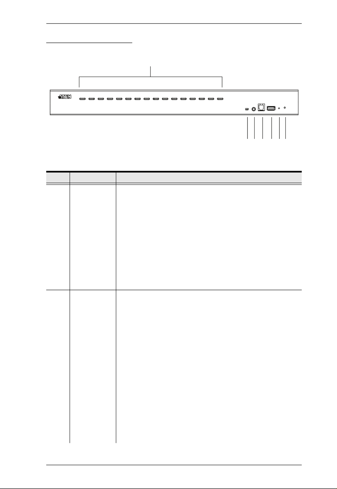
Components
Front View CS1798
No. Component Description
1 Port Selection
Pushbuttons
For manual port selection (see Port Selection, page 32, also):
Press a port selection pushbutton for less than two seconds to bring
the KVM, USB hub, and audio focus to the computer attached to its
corresponding port.
Press a pushbutton for longer than two seconds to bring the KVM
and audio focus* to the computer attached to its corresponding port.
Press pushbuttons 1 and 2 simultaneously for 2 seconds to start
Auto Scan Mode*. See Auto Scan Mode, page 51, for details.
Press pushbuttons 7 and 8 simultaneously for 2 seconds to perform
a keyboard and mouse reset. See Keyboard / Mouse Reset,
page 53, also
Note:
Enable mouse emulation for independent switching (see
page 44).
2 Port LEDs
The Port LEDs are built into the Port Selection Switches. The left ones
are the KVM Port LEDs; the right ones are the USB LEDs:
KVM
Lights DIM ORANGE to indicate that the computer attached to the
corresponding port is up and running (On Line).
Flashes to indicate that Firmware Upgrade mode is in effect.
Changes to BRIGHT ORANGE to indicate that the computer
attached to its corresponding port is the one that has the KVM focus
(Selected).
Flashes to indicate that the computer attached to its corresponding
port is being accessed under Auto Scan mode.
USB
Lights GREEN to indicate that the computer attached to its corre-
sponding port is the one that has access to the USB peripherals.
4
3
1 & 2
5 6 78

CS1798 / CS17916 User Manual
8
3 Firmware
Upgrade
Recovery
Switch
During normal operation and while performing a firmware
upgrade, this switch should be in the NORMAL position. If a
firmware upgrade operation does not complete successfully,
this switch is used to perform a firmware upgrade recovery.
See Firmware Upgrade Recovery, page 66, for details.
4 Audio Port The cables from your main speakers plug in here. The
speakers plugged in here have priority over those in the rear
panel.
5 Firmware
Upgrade Port
The firmware upgrade cable that transfers the firmware
upgrade data from the administrator's computer to the CS1798
/ CS17916 plugs into this RJ-11 connector.
6 USB 2.0 Hub USB 2.0 peripherals (printers, scanners, etc.) can plug into this
port (this may require an extra power adapter).
Note: The USB 2.0 hub cannot be accessed through the
switch by computers on the second or third level of a cascaded
installation.
7 Reset Switch Pressing this switch performs a system reset. When the
system is reset, the switch beeps, and the port LEDs flash in
succession until the reset is complete. After the reset is
complete you can login again.
Note: This switch is recessed and must be pushed with a
small object, such as the end of a paper clip or a ballpoint pen.
8 Power LED Lights to indicate that the switch is powered up and ready to
operate.
No. Component Description
1. Introduction
9
Front View CS17916
No. Component Description
1 Port Selection
Pushbuttons
For manual port selection (see Port Selection, page 32, also):
Press a port selection pushbutton for less than two seconds to bring
the KVM, USB hub, and audio focus to the computer attached to its
corresponding port.
Press a pushbutton for longer than two seconds to bring the KVM
and audio focus* to the computer attached to its corresponding port.
Press pushbuttons 1 and 2 simultaneously for 2 seconds to start
Auto Scan Mode*. See Auto Scan Mode, page 51, for details.
Press pushbuttons 15 and 16 simultaneously for 2 seconds to per-
form a keyboard and mouse reset. See Keyboard / Mouse Reset,
page 53, also
Note: Enable mouse emulation for independent switching (see
page 44).
2 Port LEDs The Port LEDs are built into the Port Selection Switches. The
left ones are the KVM Port LEDs; the right ones are the USB
LEDs:
KVM
Lights DIM ORANGE to indicate that the computer attached to the
corresponding port is up and running (On Line).
Flashes to indicate that Firmware Upgrade mode is in effect.
Changes to BRIGHT ORANGE to indicate that the computer
attached to its corresponding port is the one that has the KVM focus
(Selected).
Flashes to indicate that the computer attached to its corresponding
port is being accessed under Auto Scan mode.
USB
Lights GREEN to indicate that the computer attached to its corre-
sponding port is the one that has access to the USB peripherals.
Note: The USB 2.0 hub cannot be accessed through the
switch by computers on the second or third level of a cascaded
installation.
1 & 2
4
356 7 8
1. Introduction
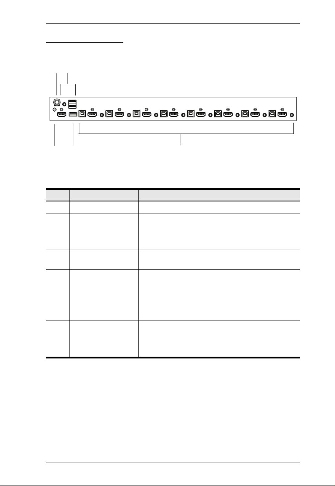
11
Rear View CS1798
No. Component Description
1 Power Jack The power adapter cable plugs in here.
2 Console Port Section The cables from your console HDMI monitor, USB
keyboard, USB mouse, and speakers plug in here.
Each connector is marked with an appropriate icon to
indicate itself.
3 Grounding Terminal The grounding wire used to ground the CS1798 /
CS17916 attaches here. (Optional)
4 USB 2.0 Hub USB 2.0 peripherals (printers, scanners, etc.) can plug
into this port (this may require an extra power
adapter).
Note: The USB 2.0 hub cannot be accessed through
the switch by computers on the second or third level of
a cascaded installation.
5 KVM Port Sections The cables that link the switch to your computers plug
in here. Each KVM port section is comprised of a
speaker jack, a USB type B socket, and HDMI
connector with screw lock.
4
35
1 2

CS1798 / CS17916 User Manual
12
Rear View CS17916
No. Component Description
1 Power Jack The power adapter cable plugs in here.
2 Console Port Section The cables from your console HDMI monitor, USB
keyboard, USB mouse, and speakers plug in here.
Each connector is marked with an appropriate icon to
indicate itself.
3 Grounding Terminal The grounding wire used to ground the CS1798 /
CS17916 attaches here. (Optional)
4 USB 2.0 Hub USB 2.0 peripherals (printers, scanners, etc.) can plug
into this port (this may require an extra power
adapter).
Note: The USB 2.0 hub cannot be accessed through
the switch by computers on the second or third level of
a cascaded installation.
5 KVM Port Sections The cables that link the switch to your computers plug
in here. Each KVM port section is comprised of a
speaker jack, a USB type B socket, and HDMI
connector with screw lock.
5
4
3
12
CS1798 / CS17916 User Manual
14
Stacking and Rack Mounting
The CS1798 / CS17916 can be stacked on the desktop or rack mounted at the
front or rear of the rack. The following sections take you through the
procedures for each method.
Note: 1. Allow at least 5.1 cm on each side for adequate ventilation and
12.7 cm at the rear for power cord and cable clearance.
2. The standard rack mounting kit does not include screws or cage nuts.
If you need additional screws or cage nuts, contact your rack dealer.
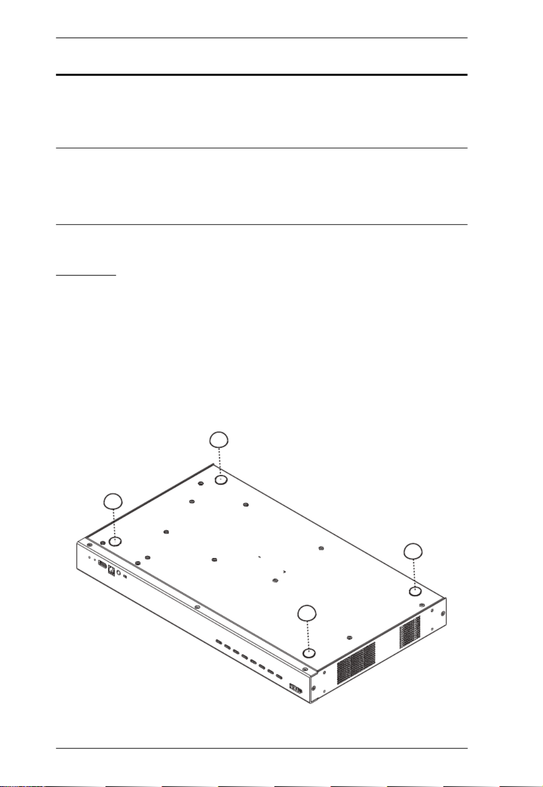
Stacking
The CS1798 / CS17916 can be placed on any level surface that can safely
support its weight and the weight of the attached cables. Make sure that the
surface is clean and free of any materials that can block the exhaust vents or
otherwise interfere with normal operation of the switch.
To place the CS1798 / CS17916, or to stack units if you are cascading them,
remove the backing material from the bottom of the rubber feet that came with
this package, and stick them onto the bottom panel at the corners, as shown in
the diagram, below:

2. Hardware Setup
15
Rack Mounting – Front
1. Remove the screws, one each from the left and right sides of the switch
near the front of the switch.
2. Use the M3 x 8 Phillips hex head screws supplied with the rack mounting kit
to screw the rack mounting brackets into the sides near the front of the unit.
(Continues on next page.)

2. Hardware Setup
17
Rack Mounting – Rear
1. Remove the screws, one each from the left and right sides of the switch
near the rear of the unit.
2. Use the M3 x 8 Phillips hex head screws supplied with the rack mounting kit
to screw the rack mounting brackets into the sides near the rear of the unit.
(Continues on next page.)

CS1798 / CS17916 User Manual
18
(Continued from previous page.)
3. Place the KVM switch in the rack. Position it so that the holes in the
mounting brackets line up with the holes in the rack. Secure the mounting
brackets to the rear of the rack.

2. Hardware Setup
19
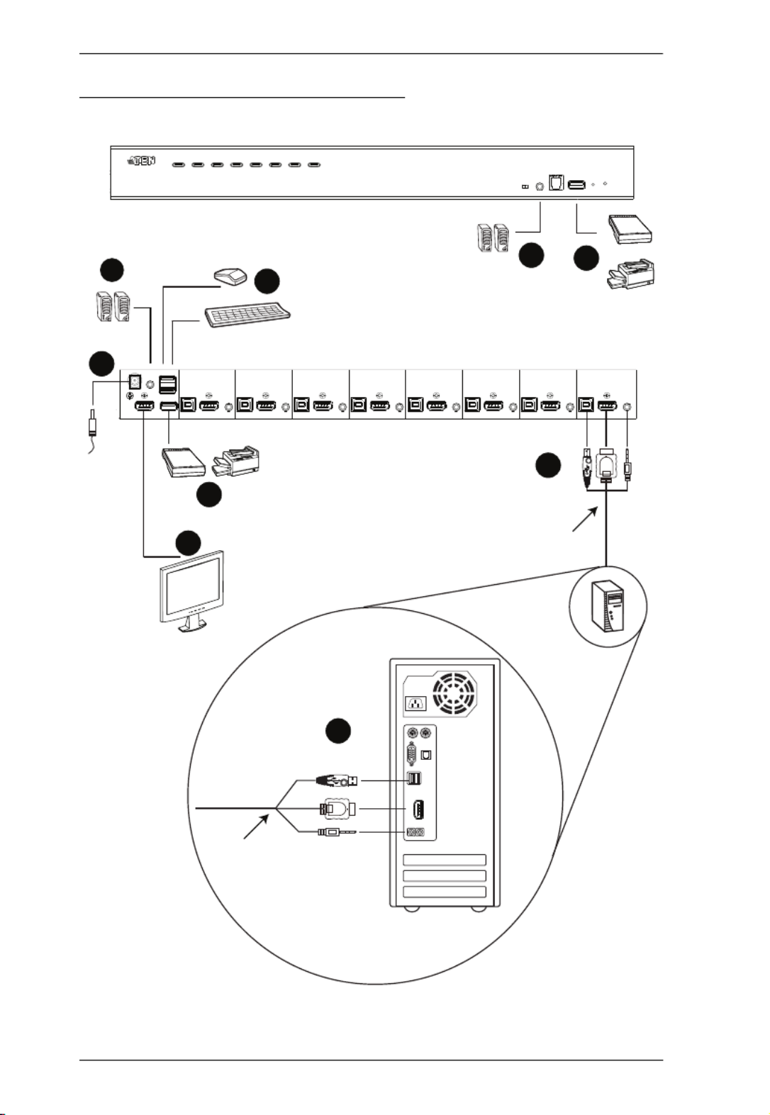
Single Stage Installation
To set up your single stage CS1798 / CS17916 installation, refer to the
installation diagram on page 20 (the numbers in the diagrams correspond to the
steps, below), and do the following:
1. Plug your USB keyboard and USB mouse into the USB console ports
located on the unit’s rear panel.
2. Connect your HDMI monitor into the HDMI console port and power on.
3. Plug your main speakers into the speaker jack located on the unit’s front
panel. The speakers plugged into this port have priority over those plugged
into the rear panel.
4. Plug your secondary speakers into the audio port located on the unit’s rear
panel.
5. Using the custom USB HDMI KVM cable set provided with this package,
plug the HDMI connector into any available HDMI socket in the KVM
port section of the switch, then plug the accompanying USB and audio
connector into their corresponding USB and speaker sockets.
Note: 1. Verify that all the plugs are in the same KVM Port sockets (all in
Port 1, all in Port 2, etc.).
2. The CS1798/CS17916 only supports speaker ports. Do not
connect a KVM cable's microphone connector to the speaker
ports.
6. At the other end of the cable, plug the USB, video, and speaker cables into
their respective ports on the computer.
7. Plug your USB peripherals into the type A sockets in the USB hub section.
8. Plug the power adapter that came with your switch into an AC power
source, then plug power adapter cable into the switch’s Power Jack.
9. Power on the computers.
Note: Make sure the computers and devices that the CS1798 / CS17916
connects to are also properly grounded.
CS1798 / CS17916 User Manual
20
Single Stage Installation Diagram
8
4
1
37
7
2
USB HDMI
KVM Cable Set
5
HDMI
6
USB HDMI
KVM Cable Set

2. Hardware Setup
21
Two Stage Cascade
To control even more computers, additional CS1798 / CS17916 units can be
cascaded from the KVM ports of the First Stage unit. The cascaded CS1798 /
CS17916s that connect back to the First Stage unit are considered Second Stage
units. As many as 64 (CS1798) or 256 (CS17916) computers can be controlled
in a complete two stage installation. A table showing the relation between the
number of computers and the number of units needed to control them is
provided on page 73.
To set up a two stage installation, refer to the Two Stage Installation diagram
on the next page as you do the following:
1. Make sure that power to all the devices you will be connecting up,
including all preexisting devices on the installation, have been turned off.
2. Use a custom USB HDMI KVM cable set (see Cables, page 6) to connect
any available KVM Port on the First Stage unit to the Console ports of the
Second Stage unit.
Note: Plug the USB Type A connector into the lower USB (keyboard) port
in the Console section (they are both marked with a similar icon to
remind you of the correct USB port).
3. Using another custom USB HDMI KVM cable set (provided with this
package), plug the HDMI connector into any available HDMI socket in the
KVM port section of the second stage switch, then plug the accompanying
USB Type B, and speaker connectors into their corresponding USB, and
speaker sockets.
Note: 1. Verify that all the plugs are in the same KVM Port sockets (all in
Port 1, all in Port 2, etc.), and that each socket is marked with an
appropriate icon to indicate itself.
2. The CS1798/CS17916 only supports speaker ports. Do not
connect a KVM cable's microphone connector to the speaker
ports.
4. At the other end of the cable, plug the USB Type A, video, and speaker
cables into their respective ports on the computer.
5. Repeat steps 3 and 4 for any other computers you are connecting up.
6. For each Second Stage unit, plug the power adapter cable into its Power
Jack, then plug the power adapter into an AC source.

CS1798 / CS17916 User Manual
22
7. Plug the First Stage unit's power adapter cable into its Power Jack, then
plug the power adapter into an AC source.
8. Power on the computers.
Note:The Power On sequence requires that all Second Stage units be
powered on first. After they are all on, the First Stage units must
be powered on next. Only after all the switches have been
powered on in this sequence, can the computers be powered on.
The USB 2.0 hub cannot be accessed through the switch by
computers on the second or third level of a cascaded installation.
Make sure the computers and devices that the CS1798 / CS17916
connects to are also properly grounded.

2. Hardware Setup
23
Two Stage Installation Diagram
USB HDMI
KVM Cable Set

2. Hardware Setup
25
Three Stage Installation Diagram
USB HDMI
KVM Cable Set
USB HDMI
KVM Cable Set

CS1798 / CS17916 User Manual
26
Multi-display Installation
The CS1798 / CS17916’s multi-display feature allows you to stack two, three,
four, or up to 8 units in a dual/triple/quad-display/multi-display installation to
control up to seven (CS1798) or fifteen (CS17916) computers at once. This
installation requires slightly different cabling than the standard cascade and
offers an extra level of switching flexibility for multiple-monitor installations
where each computer is fitted with multiple video cards.
Note: In a Multi-display installation, the CS1798 can only be connected to
CS1798 units, and the CS17916 can only be connected to CS17916
units.
Cable Connections for Multi-display Installation
To set up your multi-display installation, refer to the installation diagram on the
next page (the numbers in the diagrams correspond to the steps, below), and do
the following:
1. Use a standard USB Type A-to-USB Type B cable to connect the Port 8
USB Type B port on the first stage unit to the USB Type A port in the
Console section of the second switch.
Note: Port 8 is reserved to connect the units in a multi-display installation,
so up to seven (CS1798) or fifteen (CS17916) computers can be
attached, using KVM ports 1–7 (CS1798) or ports 1–7/9–16
(CS17916) .
2. Use HDMI cables to connect the HDMI KVM port on the second CS1798
/ CS17916 unit to the second video-in port on the computers.
Note: Only HDMI video cables are necessary – the other ports in the KVM
section are not required in this installation.
3. Connect a display to the console section of the second switch.
4. Repeat steps 1–3 for any additional units, up to a total of 8 switches.
5. Connect the cables for the first switch. See Single Stage Installation,
page 19 for full details. All video, audio and peripheral devices must be
connected to the first switch.
6. Power up the CS1798 / CS17916 units, starting with the first switch, and
then power on the computers.

2. Hardware Setup
27
Note: Make sure the computers and devices that the CS1798 / CS17916
connects to are also properly grounded.

CS1798 / CS17916 User Manual
28
Multi-display Installation Diagram
5
Computers with
2/3/4 video inputs
First Switch
5
HDMI cables
5
1
USB Type B to
Type A cable
Second Switch
3
Third / Fourth
Stage Units
4
2

2. Hardware Setup
29
Grouping Ports into “Vertical” Channels
Once the cables have been connected and multi-display mode has been selected
in the OSD, the CS1798 / CS17916 auto-detects the channels and displaying
modes.Users can then assign them a channel number as the port name (the
channels are represented by the vertical columns in the diagram below). So, all
the Port 1s become Channel 1, all the Port 2s become Channel 2, ... , and all the
Port 7s become Channel 7. The ports will all be switched at the same time,
channel by channel.
Depending on the number of stages in your stack, a CS1798 / CS17916
installation offers dual display (two stages), triple display (three stages), quad
display (four stages) or multi-display (up to 8 stages) scenarios. For reference
purposes, the example shows a four-stage installation with quad display
functionality.
Note: Only one HDMI video signal can be displayed at a time, depending on
the configuration of the CS1798 / CS17916 unit on the first switch.
Channels Diagram
Ch1
Ch7 Ch6
First
Switch
Second
Switch
Third
Switch
Fourth
Switch

CS1798 / CS17916 User Manual
30
This Page Intentionally Left Blank

31
Chapter 3
Basic Operation
Hot Plugging
The CS1798 / CS17916 supports hot plugging – components can be removed
and added back into the installation by unplugging their cables from the ports
without the need to shut the unit down. In order for hot plugging to work
properly, the procedures described below must be followed:
Hot Plugging KVM Ports
In order for the OSD menus to correspond to KVM port changes, you must
manually reconfigure the OSD to reflect the new port information. See the F3
SET (page 39) and F4 ADM (page 41), functions for details.
Note: If the computer's operating system does not support hot plugging, this
function may not work properly.
Hot Plugging Console Ports
The keyboard, monitor, and mouse can all be hot plugged. When hot plugging
the mouse:
You may unplug and replug the mouse (to reset the mouse, for example),
as long as you use the same mouse.
If you plug in a different mouse, all the computers on the installation must
be shut down for 10 seconds, then restarted following the power up
sequence described under Steps 6, 7, and 8 under Two Stage Cascade,
page 21
Note: If, after hot plugging there is no response to keyboard and/or mouse
input, perform a Keyboard and Mouse Reset by simultaneously
pressing the 7 and 8 (CS1798) or 15 and 16 (CS17916) front panel
pushbuttons.
CS1798 / CS17916 User Manual
36
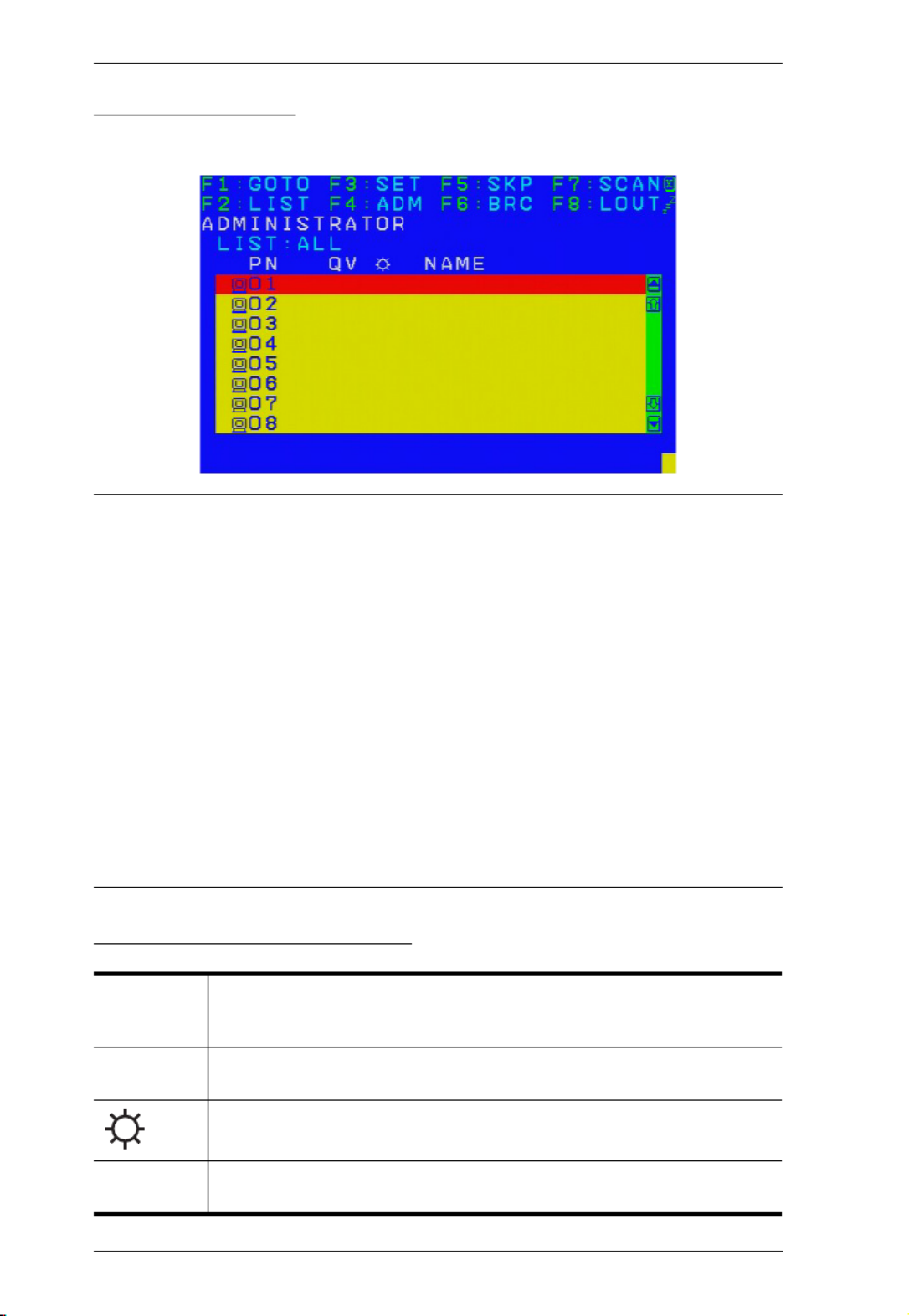
OSD Main Screen
When you invoke the OSD, a screen similar to the one below appears:
Note: 1. The diagram depicts the administrator's main screen. The user main
screen does not show the F4 and F6 functions, since these are
reserved for the administrator and can't be accessed by users.
2. The OSD always starts in list view, with the highlight bar at the same
position it was in the last time it was closed.
3. Only the ports that have been set accessible by the administrator for
the current logged in user are visible (see SET ACCESSIBLE PORTS,
page 41).
4. If the port list is collapsed, click on a switch number, or move the
highlight bar to it then press the right arrow key to expand the list.
Similarly, to collapse a switch’s port list, click on the switch number,
or move the highlight bar to it then press the left arrow key to collapse
the list.
OSD Main Screen Headings
PN This column lists the port ID numbers for all the KVM ports on the
installation. The simplest method to access a particular computer is
move the highlight bar to it, then press Enter.
QV If a port has selected for quick view scanning (see SET QUICK VIEW
PORTS, page 43), an arrowhead displays in this column.
The computers that are powered on and are online have a sun symbol
in this column.
NAME If a port has been given a name (see EDIT PORT NAMES, page 42), its
name appears in this column.

CS1798 / CS17916 User Manual
66
Firmware Upgrade Recovery
There are three conditions that call for firmware upgrade recovery:
When a firmware upgrade is manually aborted.
When the mainboard firmware upgrade fails.
When the I/O firmware upgrade fails.
To perform a firmware upgrade recovery, do the following:
1. Power off the switch.
2. Connect the Firmware Upgrade Cable to its Firmware Upgrade Port.
3. Slide the Firmware Upgrade Recovery Switch to the Recover position.
4. Power the switch back on and repeat the upgrade procedure.
5. After the switch has been successfully upgraded, power it off, and slide the
Firmware Upgrade Recovery Switch back to the Normal position.
6. If the switch is one of the cascaded switches, plug it back into the
installation.
7. Power the switch back on.
Produktspecifikationer
| Varumärke: | ATen |
| Kategori: | Växla |
| Modell: | CS1798 |
Behöver du hjälp?
Om du behöver hjälp med ATen CS1798 ställ en fråga nedan och andra användare kommer att svara dig
Växla ATen Manualer

29 December 2024
10 September 2024
10 September 2024
10 September 2024
10 September 2024
10 September 2024
10 September 2024
9 September 2024
9 September 2024
9 September 2024
Växla Manualer
- Växla Bosch
- Växla IKEA
- Växla Huawei
- Växla HP
- Växla Philips
- Växla Panasonic
- Växla Honeywell
- Växla Yamaha
- Växla Abus
- Växla Alcatel
- Växla Alecto
- Växla Apc
- Växla Alpine
- Växla Ansmann
- Växla Airlive
- Växla Edimax
- Växla Intermatic
- Växla Flamingo
- Växla Brennenstuhl
- Växla Hikvision
- Växla Generac
- Växla Silvercrest
- Växla Nedis
- Växla Pyle
- Växla Eminent
- Växla Renkforce
- Växla Vivanco
- Växla TP Link
- Växla Manhattan
- Växla Worx
- Växla Black Box
- Växla Elro
- Växla EMOS
- Växla Victron Energy
- Växla KlikaanKlikuit
- Växla Ei Electronics
- Växla Tripp Lite
- Växla DataVideo
- Växla Schneider
- Växla Hama
- Växla Theben
- Växla Elektrobock
- Växla Chamberlain
- Växla Sylvania
- Växla Velleman
- Växla Tork
- Växla Techly
- Växla Sonance
- Växla Emerson
- Växla Totolink
- Växla Vemer
- Växla Smartwares
- Växla Profile
- Växla Cisco
- Växla Matrox
- Växla Steren
- Växla Perel
- Växla Engenius
- Växla IFM
- Växla Digitus
- Växla Kathrein
- Växla AV:link
- Växla Belkin
- Växla Linksys
- Växla Buffalo
- Växla Dahua Technology
- Växla Audiovox
- Växla Cotech
- Växla Netgear
- Växla LevelOne
- Växla Kaiser
- Växla QNAP
- Växla Trotec
- Växla Boss
- Växla Behringer
- Växla PreSonus
- Växla Shimano
- Växla Merten
- Växla Goobay
- Växla Hager
- Växla Mercusys
- Växla Chacon
- Växla Elation
- Växla Sygonix
- Växla Planet
- Växla ZyXEL
- Växla Rex
- Växla Powerfix
- Växla Konig
- Växla Tesla
- Växla D-Link
- Växla Tenda
- Växla UPM
- Växla One For All
- Växla Finder
- Växla Fantini Cosmi
- Växla Audac
- Växla Marmitek
- Växla Delta Dore
- Växla DoorBird
- Växla Ubiquiti Networks
- Växla EBERLE
- Växla Grasslin
- Växla Omnitronic
- Växla Eaton
- Växla Gira
- Växla Jung
- Växla Vacmaster
- Växla CyberPower
- Växla Basetech
- Växla Trendnet
- Växla Mikrotik
- Växla WHALE
- Växla Fibaro
- Växla RGBlink
- Växla Gefen
- Växla Nexa
- Växla PAC
- Växla Wentronic
- Växla Dormakaba
- Växla Adder
- Växla Wago
- Växla Homematic IP
- Växla Monoprice
- Växla Tiptel
- Växla OSD Audio
- Växla SPC
- Växla Crestron
- Växla Unify
- Växla ORNO
- Växla Toolcraft
- Växla Berker
- Växla Aeon Labs
- Växla Electro Harmonix
- Växla Grandstream
- Växla Mercury
- Växla Provision ISR
- Växla Monacor
- Växla PCE
- Växla Logilink
- Växla Smart-AVI
- Växla StarTech.com
- Växla SIIG
- Växla Advantech
- Växla IOGEAR
- Växla Merlin Gerin
- Växla Micro Connect
- Växla Extron
- Växla KanexPro
- Växla Intelix
- Växla Blustream
- Växla Avocent
- Växla Shelly
- Växla Intellinet
- Växla Ebode
- Växla Lancom
- Växla Robbe
- Växla ICasa
- Växla B-tech
- Växla Speaka
- Växla Kopp
- Växla Vimar
- Växla Kemo
- Växla GAO
- Växla H-Tronic
- Växla Legrand
- Växla Kraus & Naimer
- Växla Noble
- Växla Intertechno
- Växla Ecler
- Växla Inverto
- Växla Triax
- Växla Rule
- Växla Kramer
- Växla CYP
- Växla Suevia
- Växla Phoenix Contact
- Växla Seuthe
- Växla Maclean Energy
- Växla SmartAVI
- Växla Leviton
- Växla DEHN
- Växla Cudy
- Växla Brilliant
- Växla Heitronic
- Växla Lindy
- Växla SEC24
- Växla Cooking Performance Group
- Växla Ernitec
- Växla Atlona
- Växla Adviti
- Växla Flic
- Växla HELGI
- Växla IB Connect
- Växla Liberty
- Växla PureTools
- Växla Hamlet
- Växla Paladin
- Växla Equip
- Växla Noark
- Växla Vivolink
- Växla Alfatron
- Växla Cambium Networks
- Växla 2USB
- Växla Roline
- Växla KVM-TEC
- Växla AMX
- Växla BZBGear
- Växla STI
- Växla Epiphan
- Växla Ebara
- Växla Mach Power
- Växla Axing
- Växla Juniper
- Växla Raritan
- Växla ConnectPro
- Växla SunBriteTV
- Växla Atlantis Land
- Växla GEV
- Växla Pizzato Elettrica
- Växla Baco
- Växla SEADA
- Växla Doepke
- Växla Comet
- Växla IPGARD
- Växla CSL
- Växla Setti+
- Växla PureLink
- Växla INOGENI
- Växla Luxul
Nyaste Växla Manualer
9 April 2025
9 April 2025
7 April 2025
5 April 2025
5 April 2025
5 April 2025
5 April 2025
3 April 2025
3 April 2025
2 April 2025