ATen KE8950-AX-E Bruksanvisning
Läs nedan 📖 manual på svenska för ATen KE8950-AX-E (250 sidor) i kategorin Växla. Denna guide var användbar för 20 personer och betygsatt med 4.5 stjärnor i genomsnitt av 2 användare
Sida 1/250

KVM Over IP Matrix System
KE6900 / KE6900ST / KE6940 / KE8950 / KE8952 /
CCKM KE Management Software
User Manual
www.aten.com

KVM Over IP Matrix System User Manual
ii
EMC Information
FEDERAL COMMUNICATIONS COMMISSION INTERFERENCE
STATEMENT: This equipment has been tested and found to comply with the
limits for a Class A digital device, pursuant to Part 15 of the FCC Rules. These
limits are designed to provide reasonable protection against harmful
interference when the equipment is operated in a commercial environment.
This equipment generates, uses, and can radiate radio frequency energy and, if
not installed and used in accordance with the instruction manual, may cause
harmful interference to radio communications. Operation of this equipment in
a residential area is likely to cause harmful interference in which case the user
will be required to correct the interference at his own expense.
The device complies with Part 15 of the FCC Rules. Operation is subject to the
following two conditions: (1) this device may not cause harmful interference,
and (2) this device must accept any interference received, including
interference that may cause undesired operation.
FCC Caution: Any changes or modifications not expressly approved by the
party responsible for compliance could void the user's authority to operate this
equipment.
Warning: Operation of this equipment in a residential environment could
cause radio interference.
Suggestion: Shielded twisted pair (STP) cables must be used with the unit to
ensure compliance with FCC & CE standards.
KCC Statement
이 기기는 업무용 (A 급 ) 전자파 적합기기로서 판매자 또는 사용자는 이
점을
주의하시기 바라며 , 가정외의 지역에서 사용하는 것을 목적으로 합니
다.
RoHS
This product is RoHS compliant.

KVM Over IP Matrix System User Manual
iii
User Information
Online Registration
Be sure to register your product at our online support center:
Telephone Support
For telephone support, call this number:
User Notice
All information, documentation, and specifications contained in this manual
are subject to change without prior notification by the manufacturer. The
manufacturer makes no representations or warranties, either expressed or
implied, with respect to the contents hereof and specifically disclaims any
warranties as to merchantability or fitness for any particular purpose. Any of
the manufacturer's software described in this manual is sold or licensed as is.
Should the programs prove defective following their purchase, the buyer (and
not the manufacturer, its distributor, or its dealer), assumes the entire cost of all
necessary servicing, repair and any incidental or consequential damages
resulting from any defect in the software.
The manufacturer of this system is not responsible for any radio and/or TV
interference caused by unauthorized modifications to this device. It is the
responsibility of the user to correct such interference.
The manufacturer is not responsible for any damage incurred in the operation
of this system if the correct operational voltage setting was not selected prior
to operation. PLEASE VERIFY THAT THE VOLTAGE SETTING IS
CORRECT BEFORE USE.
International http://eservice.aten.com
International 886-2-8692-6959
China 86-400-810-0-810
Japan 81-3-5615-5811
Korea 82-2-467-6789
North America 1-888-999-ATEN ext 4988
United Kingdom 44-8-4481-58923

KVM Over IP Matrix System User Manual
iv
Package Contents
KE6900 / KE6940
The KE6900 / KE6940 package consists of:
1 KE6900T / KE6940T KVM Over IP Transmitter
1 KE6900R / KE6940R KVM Over IP Receiver
1 USB DVI-D KVM Cable (KE6900T/KE6940T only)
1 DVI-D Cable 1.8 m (KE6940T only)
1 Foot Pad Set
2 Power Adapters
1 Mounting Kit
1 User Instructions*
KE6900ST
The KE6900ST package consists of:
1 KE6900ST Slim KVM Over IP Transmitter
1 USB DVI-D KVM Cable
1 Foot Pad Set
1 Power Adapter
1 Mounting Kit
1 User Instructions*
KE8950 / KE8952
The KE8950 / KE8952 package consists of:
1 KE8950T / KE8952T KVM Over IP Transmitter
1 KE8950R / KE8952R KVM Over IP Receiver
1 USB HDMI KVM Cable
1 Foot Pad Set
2 Power Adapters (KE8950T/KE8950R only)

KVM Over IP Matrix System User Manual
v
1 Mounting Kit (KE8950T or KE8952T)
2 HDMI Lockpro
1 User Instructions*
*Features may have been added to the KE6900 / KE6900ST / KE6940 /
KE8950 / KE8952 since this manual was published. Please visit our website
to download the most up-to-date version.
Check to make sure that all of the components are present and in good order. If anything
is missing, or was damaged in shipping, contact your dealer. Read this manual
thoroughly and follow the installation and operation procedures carefully to prevent any
damage to the KE6900 / KE6900ST / KE6940 / KE8950 / KE8952 or to any other
devices on the installation.
Copyright © 2017 ATEN® International Co., Ltd.
Manual Date: 2017-08-14
Altusen and the ATEN logo are registered trademarks of ATEN International Co., Ltd. All rights reserved. All
other brand names and trademarks are the registered property of their respective owners.

KVM Over IP Matrix System User Manual
vi
Contents
EMC Information. . . . . . . . . . . . . . . . . . . . . . . . . . . . . . . . . . . . . . . . . . . . . ii
User Information . . . . . . . . . . . . . . . . . . . . . . . . . . . . . . . . . . . . . . . . . . . . . iii
Online Registration . . . . . . . . . . . . . . . . . . . . . . . . . . . . . . . . . . . . . . . . iii
Telephone Support . . . . . . . . . . . . . . . . . . . . . . . . . . . . . . . . . . . . . . . . iii
User Notice . . . . . . . . . . . . . . . . . . . . . . . . . . . . . . . . . . . . . . . . . . . . . . iii
Package Contents . . . . . . . . . . . . . . . . . . . . . . . . . . . . . . . . . . . . . . . . . . .iv
KE6900 / KE6940 . . . . . . . . . . . . . . . . . . . . . . . . . . . . . . . . . . . . . . . . .iv
KE6900ST. . . . . . . . . . . . . . . . . . . . . . . . . . . . . . . . . . . . . . . . . . . . . . .iv
KE8950 / KE8952 . . . . . . . . . . . . . . . . . . . . . . . . . . . . . . . . . . . . . . . . .iv
About This Manual . . . . . . . . . . . . . . . . . . . . . . . . . . . . . . . . . . . . . . . . . . xii
Conventions . . . . . . . . . . . . . . . . . . . . . . . . . . . . . . . . . . . . . . . . . . . . xiv
Product Information . . . . . . . . . . . . . . . . . . . . . . . . . . . . . . . . . . . . . . . . .xiv
Chapter 1.
Introduction
Overview. . . . . . . . . . . . . . . . . . . . . . . . . . . . . . . . . . . . . . . . . . . . . . . . . . . 1
Features . . . . . . . . . . . . . . . . . . . . . . . . . . . . . . . . . . . . . . . . . . . . . . . . . . . 3
Requirements . . . . . . . . . . . . . . . . . . . . . . . . . . . . . . . . . . . . . . . . . . . . . . . 5
Console . . . . . . . . . . . . . . . . . . . . . . . . . . . . . . . . . . . . . . . . . . . . . . . . . 5
Computers. . . . . . . . . . . . . . . . . . . . . . . . . . . . . . . . . . . . . . . . . . . . . . . 5
Cables . . . . . . . . . . . . . . . . . . . . . . . . . . . . . . . . . . . . . . . . . . . . . . . . . . 5
Software . . . . . . . . . . . . . . . . . . . . . . . . . . . . . . . . . . . . . . . . . . . . . . . . 5
Operating Systems . . . . . . . . . . . . . . . . . . . . . . . . . . . . . . . . . . . . . . . . 7
Components . . . . . . . . . . . . . . . . . . . . . . . . . . . . . . . . . . . . . . . . . . . . . . . . 8
KE6900T (Transmitter) Front View . . . . . . . . . . . . . . . . . . . . . . . . . . . . 8
KE6900T (Transmitter) Rear View . . . . . . . . . . . . . . . . . . . . . . . . . . . . 9
KE6900R (Receiver) Front View . . . . . . . . . . . . . . . . . . . . . . . . . . . . . 10
KE6900R (Receiver) Rear View . . . . . . . . . . . . . . . . . . . . . . . . . . . . . 11
KE6940T (Transmitter) Front View . . . . . . . . . . . . . . . . . . . . . . . . . . . 12
KE6940T (Transmitter) Rear View . . . . . . . . . . . . . . . . . . . . . . . . . . . 13
KE6940R (Receiver) Front View . . . . . . . . . . . . . . . . . . . . . . . . . . . . . 14
KE6940R (Receiver) Rear View . . . . . . . . . . . . . . . . . . . . . . . . . . . . . 15
KE6900ST (Transmitter) Front, Rear and Top View. . . . . . . . . . . . . . 16
KE8950T / KE8952T (Transmitter) Front View . . . . . . . . . . . . . . . . . . 18
KE8950T / KE8952T (Transmitter) Rear View . . . . . . . . . . . . . . . . . . 19
KE8950R / KE8952R (Receiver) Front View. . . . . . . . . . . . . . . . . . . . 21
KE8950R / KE8952R (Receiver) Rear View . . . . . . . . . . . . . . . . . . . . 22
Chapter 2.
Hardware Setup
Rack Mounting . . . . . . . . . . . . . . . . . . . . . . . . . . . . . . . . . . . . . . . . . . . . . 23
KE6900T/KE6940T . . . . . . . . . . . . . . . . . . . . . . . . . . . . . . . . . . . . . . . 23
KE6900ST. . . . . . . . . . . . . . . . . . . . . . . . . . . . . . . . . . . . . . . . . . . . . . 25
Wall Mounting . . . . . . . . . . . . . . . . . . . . . . . . . . . . . . . . . . . . . . . . . . . . . . 26

KVM Over IP Matrix System User Manual
vii
KE6900T/KE6940T . . . . . . . . . . . . . . . . . . . . . . . . . . . . . . . . . . . . . . . 26
KE6900ST . . . . . . . . . . . . . . . . . . . . . . . . . . . . . . . . . . . . . . . . . . . . . . 27
KE6900 Point-to-Point Installation . . . . . . . . . . . . . . . . . . . . . . . . . . . . . . 28
KE6900 Point-to-Point Installation 1 of 2. . . . . . . . . . . . . . . . . . . . . . . 29
KE6900 Point-to-Point Installation 2 of 2 . . . . . . . . . . . . . . . . . . . . 30
KE8900 Point-to-Point Installation . . . . . . . . . . . . . . . . . . . . . . . . . . . . . . 31
KE8900 Point-to-Point Installation 1 of 2. . . . . . . . . . . . . . . . . . . . . . . 32
KE8900 Point-to-Point Installation 2 of 2 . . . . . . . . . . . . . . . . . . . . 33
KE6900ST Point-to-Point Installation . . . . . . . . . . . . . . . . . . . . . . . . . . . . 34
Setting up a LAN Installation . . . . . . . . . . . . . . . . . . . . . . . . . . . . . 34
KE6900 LAN Installation . . . . . . . . . . . . . . . . . . . . . . . . . . . . . . . . . . . . . . 36
KE6900 Network Installation Diagram 1 of 2. . . . . . . . . . . . . . . . . . . . 38
KE6900 Network Installation Diagram 2 of 2 . . . . . . . . . . . . . . . . . 39
KE8950 LAN Installation . . . . . . . . . . . . . . . . . . . . . . . . . . . . . . . . . . . . . . 40
KE8950 Network Installation Diagram 1 of 2. . . . . . . . . . . . . . . . . . . . 42
KE8950 Network Installation Diagram 2 of 2 . . . . . . . . . . . . . . . . . 43
Network Configuration. . . . . . . . . . . . . . . . . . . . . . . . . . . . . . . . . . . . . . . . 44
Exit OSD . . . . . . . . . . . . . . . . . . . . . . . . . . . . . . . . . . . . . . . . . . . . . . . 45
Default IP Addresses . . . . . . . . . . . . . . . . . . . . . . . . . . . . . . . . . . . . . . . . 45
KE I/O Ports . . . . . . . . . . . . . . . . . . . . . . . . . . . . . . . . . . . . . . . . . . . . . . . 46
Chapter 3.
OSD Operation
Overview . . . . . . . . . . . . . . . . . . . . . . . . . . . . . . . . . . . . . . . . . . . . . . . . . . 47
LED Display . . . . . . . . . . . . . . . . . . . . . . . . . . . . . . . . . . . . . . . . . . . . . . . 47
Invoking the OSD . . . . . . . . . . . . . . . . . . . . . . . . . . . . . . . . . . . . . . . . . . . 48
Microphone Hotkey . . . . . . . . . . . . . . . . . . . . . . . . . . . . . . . . . . . . . . . 48
Touch Screen Calibration . . . . . . . . . . . . . . . . . . . . . . . . . . . . . . . . . .48
OSD Interface . . . . . . . . . . . . . . . . . . . . . . . . . . . . . . . . . . . . . . . . . . . . . . 49
User Station Configuration . . . . . . . . . . . . . . . . . . . . . . . . . . . . . . . . . . . .50
Network . . . . . . . . . . . . . . . . . . . . . . . . . . . . . . . . . . . . . . . . . . . . . . . . 50
Properties . . . . . . . . . . . . . . . . . . . . . . . . . . . . . . . . . . . . . . . . . . . . . . 51
System . . . . . . . . . . . . . . . . . . . . . . . . . . . . . . . . . . . . . . . . . . . . . . . . 53
Transmitter Configuration . . . . . . . . . . . . . . . . . . . . . . . . . . . . . . . . . . . . . 54
Network . . . . . . . . . . . . . . . . . . . . . . . . . . . . . . . . . . . . . . . . . . . . . . . . 54
Properties . . . . . . . . . . . . . . . . . . . . . . . . . . . . . . . . . . . . . . . . . . . . . . 55
System . . . . . . . . . . . . . . . . . . . . . . . . . . . . . . . . . . . . . . . . . . . . . . . . 58
User Preferences . . . . . . . . . . . . . . . . . . . . . . . . . . . . . . . . . . . . . . . . . . . 59
Connecting . . . . . . . . . . . . . . . . . . . . . . . . . . . . . . . . . . . . . . . . . . . . . . . . 60
Connections Page . . . . . . . . . . . . . . . . . . . . . . . . . . . . . . . . . . . . . . . .61
List Mode . . . . . . . . . . . . . . . . . . . . . . . . . . . . . . . . . . . . . . . . . . . .61
Array Mode . . . . . . . . . . . . . . . . . . . . . . . . . . . . . . . . . . . . . . . . . . 63
Profile / Video Wall Page. . . . . . . . . . . . . . . . . . . . . . . . . . . . . . . . . . . 65
Push Content. . . . . . . . . . . . . . . . . . . . . . . . . . . . . . . . . . . . . . . . . . . .67
Pull Content. . . . . . . . . . . . . . . . . . . . . . . . . . . . . . . . . . . . . . . . . . . . .69

KVM Over IP Matrix System User Manual
viii
Chapter 4.
Software Installation
Overview. . . . . . . . . . . . . . . . . . . . . . . . . . . . . . . . . . . . . . . . . . . . . . . . . . 71
Download - Trial Version . . . . . . . . . . . . . . . . . . . . . . . . . . . . . . . . . . . . . 71
KE Management Software Install . . . . . . . . . . . . . . . . . . . . . . . . . . . . . . . 73
Upgrading Trial Version . . . . . . . . . . . . . . . . . . . . . . . . . . . . . . . . . . . . . . 76
Chapter 5.
Browser / Telnet Operation
Overview. . . . . . . . . . . . . . . . . . . . . . . . . . . . . . . . . . . . . . . . . . . . . . . . . . 77
Logging In . . . . . . . . . . . . . . . . . . . . . . . . . . . . . . . . . . . . . . . . . . . . . . . . . 77
The Matrix Manager Main Page . . . . . . . . . . . . . . . . . . . . . . . . . . . . . . . . 78
Web Components . . . . . . . . . . . . . . . . . . . . . . . . . . . . . . . . . . . . . . . . 78
Tree View Considerations. . . . . . . . . . . . . . . . . . . . . . . . . . . . . . . . . . 79
The Tab Bar . . . . . . . . . . . . . . . . . . . . . . . . . . . . . . . . . . . . . . . . . . . . 80
Telnet . . . . . . . . . . . . . . . . . . . . . . . . . . . . . . . . . . . . . . . . . . . . . . . . . . . . 81
Configuration Menu. . . . . . . . . . . . . . . . . . . . . . . . . . . . . . . . . . . . . . . 81
Main Menu. . . . . . . . . . . . . . . . . . . . . . . . . . . . . . . . . . . . . . . . . . . 81
1. Network . . . . . . . . . . . . . . . . . . . . . . . . . . . . . . . . . . . . . . . . . . . 82
2. Properties . . . . . . . . . . . . . . . . . . . . . . . . . . . . . . . . . . . . . . . . . 82
3. System . . . . . . . . . . . . . . . . . . . . . . . . . . . . . . . . . . . . . . . . . . . 83
Chapter 6.
Dashboard
Overview. . . . . . . . . . . . . . . . . . . . . . . . . . . . . . . . . . . . . . . . . . . . . . . . . . 84
Active Connections . . . . . . . . . . . . . . . . . . . . . . . . . . . . . . . . . . . . . . . 85
Active Sessions. . . . . . . . . . . . . . . . . . . . . . . . . . . . . . . . . . . . . . . . . . 86
Online User Stations . . . . . . . . . . . . . . . . . . . . . . . . . . . . . . . . . . . . . . 87
Online Transmitters. . . . . . . . . . . . . . . . . . . . . . . . . . . . . . . . . . . . . . . 88
Latest Events . . . . . . . . . . . . . . . . . . . . . . . . . . . . . . . . . . . . . . . . . . . 89
Schedule . . . . . . . . . . . . . . . . . . . . . . . . . . . . . . . . . . . . . . . . . . . . . . . 90
Chapter 7.
Device Management
Overview. . . . . . . . . . . . . . . . . . . . . . . . . . . . . . . . . . . . . . . . . . . . . . . . . . 91
User Stations . . . . . . . . . . . . . . . . . . . . . . . . . . . . . . . . . . . . . . . . . . . . . . 92
Adding a User Station . . . . . . . . . . . . . . . . . . . . . . . . . . . . . . . . . . . . . 93
Configuring a User Station . . . . . . . . . . . . . . . . . . . . . . . . . . . . . . . . . . . . 94
Deleting a User Station . . . . . . . . . . . . . . . . . . . . . . . . . . . . . . . . . . . . 99
User Station Video Group. . . . . . . . . . . . . . . . . . . . . . . . . . . . . . . . . . . . 100
Hardware Setup . . . . . . . . . . . . . . . . . . . . . . . . . . . . . . . . . . . . . . . . 100
Adding a User Station Video Group . . . . . . . . . . . . . . . . . . . . . . . . . 101
Transmitters . . . . . . . . . . . . . . . . . . . . . . . . . . . . . . . . . . . . . . . . . . . . . . 103
Adding a Transmitter. . . . . . . . . . . . . . . . . . . . . . . . . . . . . . . . . . . . . 104
Configuring a Transmitter . . . . . . . . . . . . . . . . . . . . . . . . . . . . . . . . . . . . 105
Deleting a Transmitter. . . . . . . . . . . . . . . . . . . . . . . . . . . . . . . . . . . . 109

KVM Over IP Matrix System User Manual
ix
Channel Connections . . . . . . . . . . . . . . . . . . . . . . . . . . . . . . . . . . . . . . . 110
Channels . . . . . . . . . . . . . . . . . . . . . . . . . . . . . . . . . . . . . . . . . . . . . . . . . 111
Adding a Channel . . . . . . . . . . . . . . . . . . . . . . . . . . . . . . . . . . . . . . . 112
Channel Groups . . . . . . . . . . . . . . . . . . . . . . . . . . . . . . . . . . . . . . . . . . . 115
Adding a Channel Group. . . . . . . . . . . . . . . . . . . . . . . . . . . . . . . . . . 115
Profiles . . . . . . . . . . . . . . . . . . . . . . . . . . . . . . . . . . . . . . . . . . . . . . . . . .117
Adding a Profile . . . . . . . . . . . . . . . . . . . . . . . . . . . . . . . . . . . . . . . . . 118
Video Wall. . . . . . . . . . . . . . . . . . . . . . . . . . . . . . . . . . . . . . . . . . . . . . . .121
Video Wall Example . . . . . . . . . . . . . . . . . . . . . . . . . . . . . . . . . . . . . 122
Adding a Video Wall . . . . . . . . . . . . . . . . . . . . . . . . . . . . . . . . . . . . . 123
Chapter 8.
User Management
Overview . . . . . . . . . . . . . . . . . . . . . . . . . . . . . . . . . . . . . . . . . . . . . . . . . 127
Users. . . . . . . . . . . . . . . . . . . . . . . . . . . . . . . . . . . . . . . . . . . . . . . . . . . .128
Adding Users. . . . . . . . . . . . . . . . . . . . . . . . . . . . . . . . . . . . . . . . . . . 128
Modifying User Accounts. . . . . . . . . . . . . . . . . . . . . . . . . . . . . . . . . . 130
Deleting User Accounts. . . . . . . . . . . . . . . . . . . . . . . . . . . . . . . . . . . 130
Groups . . . . . . . . . . . . . . . . . . . . . . . . . . . . . . . . . . . . . . . . . . . . . . . . . .131
Creating Groups . . . . . . . . . . . . . . . . . . . . . . . . . . . . . . . . . . . . . . . . 131
Modifying Groups . . . . . . . . . . . . . . . . . . . . . . . . . . . . . . . . . . . . . . . 132
Deleting Groups . . . . . . . . . . . . . . . . . . . . . . . . . . . . . . . . . . . . . . . . 132
Users and Groups . . . . . . . . . . . . . . . . . . . . . . . . . . . . . . . . . . . . . . . . . . 133
Assigning Users to a Group From the User’s Notebook . . . . . . . . . . 133
Removing Users From a Group From the User’s Notebook . . . . . . . 134
Assigning Users to a Group From the Group’s Notebook . . . . . . . . . 135
Removing Users From a Group From the Group’s Notebook . . . . . . 136
Device . . . . . . . . . . . . . . . . . . . . . . . . . . . . . . . . . . . . . . . . . . . . . . . . . . .137
Assigning Device Permissions From the User’s Notebook . . . . . . . . 137
Assigning Device Permissions From the Groups’ Notebook . . . . . . . 139
Profiles/Video Walls . . . . . . . . . . . . . . . . . . . . . . . . . . . . . . . . . . . . . . . . 140
Assigning Profile/Video Wall Permissions From the User’s Notebook . .
140
Chapter 9.
System
Overview . . . . . . . . . . . . . . . . . . . . . . . . . . . . . . . . . . . . . . . . . . . . . . . . . 142
Global Settings . . . . . . . . . . . . . . . . . . . . . . . . . . . . . . . . . . . . . . . . .143
ANMS . . . . . . . . . . . . . . . . . . . . . . . . . . . . . . . . . . . . . . . . . . . . . . . . 147
Event Destination. . . . . . . . . . . . . . . . . . . . . . . . . . . . . . . . . . . . . 147
Authentication & Authorization. . . . . . . . . . . . . . . . . . . . . . . . . . . 149
Redundancy . . . . . . . . . . . . . . . . . . . . . . . . . . . . . . . . . . . . . . . . . . . 152
Chapter 10.
Logs
Overview . . . . . . . . . . . . . . . . . . . . . . . . . . . . . . . . . . . . . . . . . . . . . . . . . 156

KVM Over IP Matrix System User Manual
x
System Log. . . . . . . . . . . . . . . . . . . . . . . . . . . . . . . . . . . . . . . . . . . . . . . 157
Filter . . . . . . . . . . . . . . . . . . . . . . . . . . . . . . . . . . . . . . . . . . . . . . . . . 159
Chapter 11.
Maintenance
Overview. . . . . . . . . . . . . . . . . . . . . . . . . . . . . . . . . . . . . . . . . . . . . . . . . 160
Backup / Restore . . . . . . . . . . . . . . . . . . . . . . . . . . . . . . . . . . . . . . . . . . 161
Backup . . . . . . . . . . . . . . . . . . . . . . . . . . . . . . . . . . . . . . . . . . . . . . . 162
Restore . . . . . . . . . . . . . . . . . . . . . . . . . . . . . . . . . . . . . . . . . . . . . . . 162
Firmware Upgrade . . . . . . . . . . . . . . . . . . . . . . . . . . . . . . . . . . . . . . . . . 163
Firmware Upgrade Recovery . . . . . . . . . . . . . . . . . . . . . . . . . . . . . . 164
Certificates . . . . . . . . . . . . . . . . . . . . . . . . . . . . . . . . . . . . . . . . . . . . . . . 165
Private Certificate . . . . . . . . . . . . . . . . . . . . . . . . . . . . . . . . . . . . 165
Certificate Signing Request. . . . . . . . . . . . . . . . . . . . . . . . . . . . . 166
Preferences . . . . . . . . . . . . . . . . . . . . . . . . . . . . . . . . . . . . . . . . . . . . . . 168
Chapter 12.
Firmware Upgrade Utility
Preparation . . . . . . . . . . . . . . . . . . . . . . . . . . . . . . . . . . . . . . . . . . . . . . . 170
Starting the Upgrade. . . . . . . . . . . . . . . . . . . . . . . . . . . . . . . . . . . . . . . . 171
Upgrade Succeeded . . . . . . . . . . . . . . . . . . . . . . . . . . . . . . . . . . . . . . . . 173
Firmware Upgrade Recovery . . . . . . . . . . . . . . . . . . . . . . . . . . . . . . . . . 174
Chapter 13.
CLI Commands
Serial Control Protocol Commands . . . . . . . . . . . . . . . . . . . . . . . . . . . . 175
Configuring the Serial Port . . . . . . . . . . . . . . . . . . . . . . . . . . . . . . . . 175
Device/Profile Commands. . . . . . . . . . . . . . . . . . . . . . . . . . . . . . . . . 175
Verification . . . . . . . . . . . . . . . . . . . . . . . . . . . . . . . . . . . . . . . . . . . . 175
Switch Port Command . . . . . . . . . . . . . . . . . . . . . . . . . . . . . . . . . . . 177
Mute Command. . . . . . . . . . . . . . . . . . . . . . . . . . . . . . . . . . . . . . . . . 181
Profile Command . . . . . . . . . . . . . . . . . . . . . . . . . . . . . . . . . . . . . . . 183
EDID Command . . . . . . . . . . . . . . . . . . . . . . . . . . . . . . . . . . . . . . . . 185
Reset Command . . . . . . . . . . . . . . . . . . . . . . . . . . . . . . . . . . . . . . . . 187
RS-232 Command . . . . . . . . . . . . . . . . . . . . . . . . . . . . . . . . . . . . . . 188
OSD Command. . . . . . . . . . . . . . . . . . . . . . . . . . . . . . . . . . . . . . . . . 191
List Command . . . . . . . . . . . . . . . . . . . . . . . . . . . . . . . . . . . . . . . . . . 192
Read Command . . . . . . . . . . . . . . . . . . . . . . . . . . . . . . . . . . . . . . . . 194
Set Command . . . . . . . . . . . . . . . . . . . . . . . . . . . . . . . . . . . . . . . . . . 198
Appendix
Safety Instructions . . . . . . . . . . . . . . . . . . . . . . . . . . . . . . . . . . . . . . . . . 207
General . . . . . . . . . . . . . . . . . . . . . . . . . . . . . . . . . . . . . . . . . . . . . . . 207
Rack Mounting . . . . . . . . . . . . . . . . . . . . . . . . . . . . . . . . . . . . . . . . . 209
Technical Support. . . . . . . . . . . . . . . . . . . . . . . . . . . . . . . . . . . . . . . . . . 210
International . . . . . . . . . . . . . . . . . . . . . . . . . . . . . . . . . . . . . . . . . . . 210
North America . . . . . . . . . . . . . . . . . . . . . . . . . . . . . . . . . . . . . . . . . . 210

KVM Over IP Matrix System User Manual
xi
Specifications . . . . . . . . . . . . . . . . . . . . . . . . . . . . . . . . . . . . . . . . . . . . .211
KE6900T / KE6940T . . . . . . . . . . . . . . . . . . . . . . . . . . . . . . . . . . . . . 211
KE6900R / KE6940R. . . . . . . . . . . . . . . . . . . . . . . . . . . . . . . . . . . . . 213
KE6900ST . . . . . . . . . . . . . . . . . . . . . . . . . . . . . . . . . . . . . . . . . . . . . 214
KE8950T / KE8952T . . . . . . . . . . . . . . . . . . . . . . . . . . . . . . . . . . . . . 215
KE8950R / KE8952R. . . . . . . . . . . . . . . . . . . . . . . . . . . . . . . . . . . . . 216
Optional Rack Mounting . . . . . . . . . . . . . . . . . . . . . . . . . . . . . . . . . . . . . 217
Dual Rack Mounting . . . . . . . . . . . . . . . . . . . . . . . . . . . . . . . . . . . . . 217
Single Rack Mounting . . . . . . . . . . . . . . . . . . . . . . . . . . . . . . . . . . . .220
IP Installer . . . . . . . . . . . . . . . . . . . . . . . . . . . . . . . . . . . . . . . . . . . . . . . .222
Trusted Certificates . . . . . . . . . . . . . . . . . . . . . . . . . . . . . . . . . . . . . . . . .223
Overview . . . . . . . . . . . . . . . . . . . . . . . . . . . . . . . . . . . . . . . . . . . . . .223
Self-Signed Private Certificates . . . . . . . . . . . . . . . . . . . . . . . . . . . . . . . 224
Examples. . . . . . . . . . . . . . . . . . . . . . . . . . . . . . . . . . . . . . . . . . . . . .224
Importing the Files. . . . . . . . . . . . . . . . . . . . . . . . . . . . . . . . . . . . . . . 224
RS-232 Pin Assignments . . . . . . . . . . . . . . . . . . . . . . . . . . . . . . . . . . . . 225
Transmitter Front RS-232 Port . . . . . . . . . . . . . . . . . . . . . . . . . . 225
Multicast IP Address . . . . . . . . . . . . . . . . . . . . . . . . . . . . . . . . . . . . . . . . 226
KE Multicast Rule . . . . . . . . . . . . . . . . . . . . . . . . . . . . . . . . . . . . . . .226
Multicast IP Formula . . . . . . . . . . . . . . . . . . . . . . . . . . . . . . . . . . . . .226
If X is between 0 ~ 127 . . . . . . . . . . . . . . . . . . . . . . . . . . . . . . . . 226
If X is between 128 ~ 192 . . . . . . . . . . . . . . . . . . . . . . . . . . . . . . 227
If X is 192 or higher . . . . . . . . . . . . . . . . . . . . . . . . . . . . . . . . . . . 227
Keys to Network Performance . . . . . . . . . . . . . . . . . . . . . . . . . . . . . . . . 228
Build a Network Diagram. . . . . . . . . . . . . . . . . . . . . . . . . . . . . . . . . . 228
Other Factors. . . . . . . . . . . . . . . . . . . . . . . . . . . . . . . . . . . . . . . . 228
Choose a High Performance Switch . . . . . . . . . . . . . . . . . . . . . . . . . 230
Layer 2 or Layer 3 Switches . . . . . . . . . . . . . . . . . . . . . . . . . . . .230
Considerations . . . . . . . . . . . . . . . . . . . . . . . . . . . . . . . . . . . . . . . . .230
Number of ports. . . . . . . . . . . . . . . . . . . . . . . . . . . . . . . . . . . . . . 230
Stackable verse Standalone . . . . . . . . . . . . . . . . . . . . . . . . . . . . 230
What Stackable Switches Can do:. . . . . . . . . . . . . . . . . . . . . . . .231
Switch Specifications . . . . . . . . . . . . . . . . . . . . . . . . . . . . . . . . . . 231
Configuring Switches and KE Devices . . . . . . . . . . . . . . . . . . . . . . . 232
KE transmitter Settings: . . . . . . . . . . . . . . . . . . . . . . . . . . . . . . . . 232
Limited Hardware Warranty . . . . . . . . . . . . . . . . . . . . . . . . . . . . . . . . . . 233
What is covered by the Limited Hardware Warranty . . . . . . . . . . . . .233

KVM Over IP Matrix System User Manual
xii
About This Manual
This User Manual is provided to help you get the most from your KVM Over
IP Matrix System. It covers all aspects of installation, configuration and
operation. An overview of the information found in the manual is provided
below.
Chapter 1, Introduction, introduces you to the KVM Over IP Matrix
System. Its purpose, features and benefits are presented, and its front and back
panel components are described.
Chapter 2, Hardware Setup, provides step-by-step instructions for setting
up your installation, and explains some basic operation procedures.
Chapter 3, OSD Operation, explains the fundamental concepts involved in
operating the KE6900 / KE6900ST / KE6940 / KE8950 / KE8952, and
provides a complete description of the On Screen Displays (OSDs) and how to
work with them.
Chapter 4, Software Installation, explains the administrative procedures
that are required to download and install the Matrix Manager software.
Chapter 5, Browser / Telnet Operation, explains how to log in to the
Matrix Manager with a web browser, and describes the features, functions, and
how to work with the browser's interface.
Chapter 6, Dashboard, explains how to use the Matrix Manager’s
Dashboard tab to view connection, session, and device events.
Chapter 7, Device Management, explains how to add, configure, and
organize the Transmitter and Receiver devices that will be managed over the
network, as well as how to create Channels and Profiles for matrix connections.
Chapter 8, User Management, describes how to add, modify and delete
user accounts; create user groups and assign users to them; specify access
rights for users and groups; and specify user authentication.
Chapter 9, System, explains the Matrix Manager’s global settings, and
ANMS settings for LDAP/AD, RADIUS, and TACACS+ authentication and
authorization.
Chapter 10, Logs, explains how to access, filter, and search the various logs
that are kept by the Matrix Manager.
Chapter 11, Maintenance, explains how to use the Matrix Manager's
Maintenance tab to backup, restore, upgrade firmware, install certificates, and
set user preferences.

KVM Over IP Matrix System User Manual
xiii
Chapter 12, Firmware Upgrade Utility, explains how to download and
use the Firmware Upgrade Utility to install new firmware on the devices.
Chapter 13, CLI Commands, provides a complete list of the serial
protocol and TCP/IP commands used when utilizing the RS-232 Serial Port or
a network connection to configure the KE devices.
An Appendix, at the end of the manual provides technical and
troubleshooting information.

KVM Over IP Matrix System User Manual
xiv
Conventions
This manual uses the following conventions:
Product Information
For information about all ATEN products and how they can help you connect
without limits, visit ATEN on the Web or contact an ATEN Authorized
Reseller. Visit ATEN on the Web for a list of locations and telephone numbers:
Monospaced Indicates text that you should key in.
[ ] Indicates keys you should press. For example, [Enter] means
to press the Enter key. If keys need to be chorded, they appear
together in the same bracket with a plus sign between them:
[Ctrl+Alt].
1. Numbered lists represent procedures with sequential steps.
♦Bullet lists provide information, but do not involve sequential
steps.
→Indicates selecting the option (on a menu or dialog box, for
example), that comes next. For example, Start → Run means
to open the Start menu, and then select Run.
Indicates critical information.
International http://www.aten.com
North America http://www.aten-usa.com

1
Chapter 1
Introduction
Overview
The KVM Over IP Matrix System is a solution that combines KE Series
Extenders (KE6900, KE6940, KE6900ST, KE8950, KE8952) with the KE
Management Software (CCKM) to ex monitor access to tend, control and
computers, across a network, in a multitude of ways. The system lets you setup
a matrix of remote KVM consoles that access computers across a network, with
the flexibility to control and configure each connection.
The KE Extenders consist of transmitters that connects to the computer and
receivers that provide console access from a separate location. The computer
is accessed from the remote console via a standard TCP/IP network or direct
Ethernet cable connection. This is perfect for any installation where you need
to place the console where it is convenient, but you want the computer to reside
in a secure location - away from the keyboard, mouse and display.
The KE6900 is a single view extender that supports one DVI display at each
end. The KE6940 is a dual view extender that supports two DVI displays at
each end, allowing the video output to display across two monitors.
The KE8950 and KE8952 are single view 4K HDMI extenders that support
HDCP 1.4 and HDMI 1.4a. The KE8900 Series connect unit-to-unit or over a
TCP/IP network via a Gigabit Ethernet or SFP port. Both models support Fiber
Channel over Ethernet via SFP fiber modules* which connect to a network
switch at speeds up to 1 Gbps. Additionally, the KE8952’s Gigabit LAN port
supports Power over Ethernet (PoE) which provides a network connection and
powers the unit from a network switch over Cat 5e cable.
The KE Extenders have a local On Screen Display (OSD) on the receiver end
to configure both units - for easy setup and operation. Both the transmitter and
receiver have RS-232 ports to connect to a serial terminal for configuration or
serial devices such as touchscreens and barcode scanners.
As KVM over IP Matrix Extenders they can make console-to-computer
connections in several ways: one-to-one (Extender mode), one-to-many
(Splitter mode), many-to-one (Switch mode), or many-to-many (Matrix mode).
The KE Management Software (CCKM) allows you to define matrix
connections and manage KE Extenders with features such as auto-detection of
KE Extenders, username/password authentication, switching and sharing of

KVM Over IP Matrix System User Manual
2
connections, scheduling, permissions and more. Whether you're extending
computer access for Monitoring, Broadcasting, Editing or Workstation setup,
the KVM Over IP Matrix System gives you the flexibility and control to
manage one or hundreds of extended connections.
Note: The SFP module is sold separately. You can choose the 2A-136G, a
multi-mode SFP module that provides 1 GbE connectivity up to 550 meters; or
the 2A-137G, a single-mode SFP module that provides 1 GbE connectivity up
to 10 kilometers. Visit ATEN's website or contact your ATEN dealer for more
information.

Chapter 1. Introduction
3
Features
Remote KVM console access of computers over LAN or Ethernet cable
connection
Dual console operation – control your system from both the Transmitter
and Receiver by USB keyboard, monitor, and mouse
RS-232 serial ports allows you to connect to a serial terminal for
configuration, and serial devices such as touchscreens and barcode
scanners1
Superior video quality – up to 1920 x 1200 @ 60 Hz with 24-bit color
depth (KE6900 series); up to 3840 x 2160 @ 30 Hz (4:4:4) with 24-bit
color depth (KE8900 series)
Supports standard VGA resolutions from 640 x 480 to 1920 x 1200 @ 60
Hz (KE6900 series); and HDMI resolutions from 640 x 480 to 3840 x
2160 @ 30 Hz (KE8950 series)
OSD (On Screen Display) on the Receiver configures both units
Supports KE Management Web GUI administration2
KE Management Lite provides web GUI support for smaller installations
3
Supports Power over Ethernet (PoE) functionality – compliant with IEEE
802.3at and 802.3af standards (KE8952 only)
Gigabit Ethernet port
Remote login security
DVI digital and analog monitor support
Built-in ESD protection and surge protection
Supports 2 channel analog (KE6900 series) and 7.1 channel surround
sound (KE8950 series) stereo speakers and microphone
Auto-MDIX - automatically detects cable type
Supports widescreen formats
Supports High-Quality Video streaming
Virtual Media Support
Hot pluggable
Rack Mountable
Upgradeable firmware
Note: 1. RS-232 serial ports support Tx/Rx/CTS/RTS/DTR/DSR signals only.

KVM Over IP Matrix System User Manual
4
2. The KE Management web GUI can be updated from the CCKM page
on our website: www.aten.com. To obtain a license for the full
version of the software please contact your ATEN dealer.
3. The KE Management Lite is a web GUI that supports up to 8 KE
devices and can be downloaded for free after registering your product
on the ATEN eService website (http://eservice.aten.com).

Chapter 1. Introduction
5
Requirements
Console
(KE6900) One DVI compatible monitor capable of the highest possible
resolution
(KE6940) Two DVI compatible monitors capable of the highest possible
resolution
(KE8950/KE8952) One HDMI compatible monitor capable of the highest
possible resolution
A USB mouse
A USB keyboard
Microphone and speakers
Computers
The following equipment must be installed on each computer that is to be
connected to the system:
(KE6900) One DVI port
(KE6940) Two DVI ports
(KE8950/KE8952) One HDMI port
USB Type A port
Audio ports
Cables
For optimal signal integrity and to simplify the setup, we strongly
recommend that you only use the high quality custom USB KVM Cable
that is provided with this package.
Software
The minimum hardware and software requirements for the computer running
the KE Management software are:
Processor: Intel or AMD processor 1 GHz or above
RAM: 2GB or above
HDD: 16GB or above
Web browser
Java Runtime Environment (JRE) 6 with update 11 or higher

KVM Over IP Matrix System User Manual
6
Operating System Requirements:
Windows 2000, XP, Vista, 2003, 2008, 7 and 8.1
Linux (Ubuntu, CentOS, Fedora, SUSE)

Chapter 1. Introduction
7
Operating Systems
The KE Series supports the following operating systems which can display
standard HDMI/DVI/VGA signals:
OS Version
Windows 2000 and higher
Linux RedHat 6.0 and higher
SUSE 8.2 and higher
Mandriva (Mandrake) 9.0 and higher
UNIX AIX 4.3 and higher
FreeBSD 3.51 and higher
Sun Solaris 8 and higher
Novell Netware 5.0 and higher
Mac OS 9 and higher

KVM Over IP Matrix System User Manual
8
Components
KE6900T (Transmitter) Front View
No. Component Description
1 KVM Ports The USB KVM cable supplied with the package that
links the Transmitter to the computer plugs into these
ports.
2 RS-232 Port This RS-232 serial port is for connecting to the
computer for serial control.
3 Remote / Local LED Lights Green to indicate which side of the installation
(Local or Remote) currently has KVM control of the
computer.
4 LAN LED This LED indicates the network status.
Lights when connected to the LAN and blinks when
the Ethernet connection is active:
Orange: 10 Mbps
Orange + Green: 100 Mbps
Green: 1000 Mbps
Off when not connected to the LAN.
5 Power LED Lights blue to indicate the unit is turned on.
6 Audio Ports These mini stereo ports are for the speakers (green)
and microphone (pink).
32
6
4
1
5

Chapter 1. Introduction
9
KE6900T (Transmitter) Rear View
No. Component Description
1 Power Jack The cable from the DC Power adapter connects here.
2 Function Switch Use this slide switch to set the unit’s mode to:
Auto: Shared (simultaneous) KVM control of the
computer at the Transmitter and Receiver console.
RS-232 Config: The device is ready to be
configured via serial commands through the RS-232
port.
Local: Only the local Transmitter has KVM control
of the computer. The Receiver’s KVM access to the
computer is locked.
3 Reset This switch must be pushed with a thin object, such as
the end of a paper clip.
Press and release to reboot the device.
Power off, hold reset then power on the device
while pressing reset to recover from a firmware
upgrade failure.
Press and hold it in for more then three seconds
resets the unit back to its factory default
settings.
4 RS-232 Port This RS-232 serial port is for connecting to a serial
terminal.
5 Audio Ports These mini stereo ports are for the speakers (green)
and microphone (pink).
6 Console Ports The unit’s USB keyboard and USB mouse plug into
these ports.
7 LAN Port The cable that connects the unit to the LAN plugs in
here.
8 DVI-I Output The cable from the local DVI monitor plugs in here.
14
3
2
5
678

KVM Over IP Matrix System User Manual
10
KE6900R (Receiver) Front View
No. Component Description
1 Power LED Lights blue to indicate the unit is turned on.
2 LAN LED This LED indicates the network status.
Lights when connected to the LAN and blinks when
the Ethernet connection is active:
Orange: 10 Mbps
Orange + Green: 100 Mbps
Green: 1000 Mbps
Off when not connected to the LAN.
3 Local LED Lights green to Indicate the Transmitter has KVM
access of the computer.
4 Remote LED Lights green to Indicate the Receiver has KVM access
of the computer.
5 Graphics Pushbutton Sets the displays image quality to the highest possible
grade so that images are optimized. This toggle button
turns off the Video Pushbutton option.
Graphics mode is selected by default.
6 OSD Pushbutton Use this pushbutton to open the OSD menu.
7 Video Pushbutton Sets the displays image quality to a grade that is
optimized for video playback. This toggle button turns
off the Graphics Pushbutton option.
8 USB Port Use this port for virtual media or a USB peripheral
device.
Note: When using a USB disk plugged into this port,
see USB Mode, page 97.
143
2
Graphics OSD Video
POWER LAN LOCAL REMOTE
5678

Chapter 1. Introduction
11
KE6900R (Receiver) Rear View
No. Component Description
1 Power Jack The cable from the DC Power adapter connects here.
2 Function Switch Use this slide switch to set the unit’s mode:
Extension: Sets the device to use the normal TX to RX
extension mode.
RS-232 Config: The device is ready to be configured via
serial commands through the RS-232 port.
3 Reset This switch must be pushed with a thin object, such as the
end of a paper clip.
Press and release to reboot the device.
Power off, hold reset then power on the device while
pressing reset to recover from a firmware upgrade
failure.
Press and hold it in for more then three seconds
resets the unit back to its factory default settings.
4 RS-232 Port This RS-232 serial port is for connecting to a serial terminal.
5 Audio Ports These mini stereo ports are for the local speakers (green)
and microphone (pink).
6 USB Port Use this port for virtual media or a USB peripheral device.
Note: When using a USB disk plugged into this port, see
USB Mode, page 97.
7 Console Ports The unit’s USB keyboard and USB mouse plug into these
ports. When using a keyboard or mouse with special
functions, see USB Mode, page 97
8 LAN Port The cable that connects the unit to the LAN plugs in here.
9 DVI-I Output The cable from the local DVI monitor plugs in here.
3
124
56
789

KVM Over IP Matrix System User Manual
12
KE6940T (Transmitter) Front View
No. Component Description
1 KVM Ports The USB KVM cable supplied with the package that
links the Transmitter to the computer plugs into these
ports.
2 RS-232 Port This RS-232 serial port is for connecting to the
computer for serial control.
3 Remote / Local LED Lights green to indicate which side of the installation
(Local or Remote) has KVM control of the computer.
4 LAN LED This LED indicates the network status.
Lights when connected to the LAN and blinks when
the Ethernet connection is active:
Orange: 10 Mbps
Orange + Green: 100 Mbps
Green: 1000 Mbps
Off when not connected to the LAN.
5 Power LED Lights blue to indicate the unit is turned on.
6 Audio Ports These mini stereo ports are for the speakers (green)
and microphone (pink).
1
32
6
4 5

Chapter 1. Introduction
13
KE6940T (Transmitter) Rear View
No. Component Description
1 Power Jack The cable from the DC Power adapter connects here.
2 Function Switch Use this slide switch to set the unit’s mode to:
Auto: Shared (simultaneous) KVM control of the
computer at the Transmitter and Receiver console.
RS-232 Config: The device is ready to be
configured via serial commands through the RS-232
port.
Local: Only the local Transmitter has KVM control
of the computer. The Receiver’s KVM access to the
computer is locked.
3 Reset This switch must be pushed with a thin object, such as
the end of a paper clip.
Press and release to reboot the device.
Power off, hold reset then power on the device
while pressing reset to recover from a firmware
upgrade failure.
Press and hold it in for more then three seconds
resets the unit back to its factory default
settings.
4 RS-232 Port This RS-232 serial port is for connecting to a serial
terminal.
5 Audio Ports These mini stereo ports are for the local speakers
(green) and microphone (pink).
6 Console Ports The unit’s USB keyboard and USB mouse plug into
these ports.
7 LAN Port The cable that connects the unit to the LAN plugs in
here.
8 DVI-I Output The cable from the local DVI monitor plugs in here.
3
12 4
5
678

KVM Over IP Matrix System User Manual
14
KE6940R (Receiver) Front View
No. Component Description
1 Power LED Lights blue to indicate the unit is turned on.
2 LAN LED This LED indicates the network status.
Lights when connected to the LAN and blinks when
the Ethernet connection is active:
Orange: 10 Mbps
Orange + Green: 100 Mbps
Green: 1000 Mbps
Off when not connected to the LAN.
3 Local LED Lights green to Indicate the Transmitter has KVM
access of the computer.
4 Remote LED Lights green to Indicate the Receiver has KVM access
of the computer.
5 Graphics Pushbutton Sets the displays image quality to the highest possible
grade so that images are optimized. This toggle button
turns off the Video Pushbutton option.
Graphics mode is selected by default.
6 OSD Pushbutton Use this pushbutton to open the OSD menu.
7 Video Pushbutton Sets the displays image quality to a grade that is
optimized for video playback. This toggle button turns
off the Graphics Pushbutton option.
8 USB Port Use this port for virtual media or a USB peripheral
device.
Note: When using a USB disk plugged into this port,
see USB Mode, page 97.
143
2
Graphics OSD Video
POWER LAN LOCAL REMOTE
5678

Chapter 1. Introduction
15
KE6940R (Receiver) Rear View
No. Component Description
1 Power Jack The cable from the DC Power adapter connects here.
2 Function Switch Use this slide switch to set the unit’s mode:
Extension: Sets the device to use the normal TX to RX
extension mode.
RS-232 Config: The device is ready to be configured
via serial commands through the RS-232 port.
3 Reset This switch must be pushed with a thin object, such as the
end of a paper clip.
Press and release to reboot the device.
Power off, hold reset then power on the device
while pressing reset to recover from a firmware
upgrade failure.
Press and hold it in for more then three seconds
resets the unit back to its factory default settings.
4 RS-232 Port This RS-232 serial port is for connecting to a serial
terminal.
5 Audio Ports These mini stereo ports are for the local speakers (green)
and microphone (pink).
6 USB Port Use this port for virtual media or a USB peripheral device.
Note: When using a USB disk plugged into this port, see
USB Mode, page 97.
7 Console Ports The unit’s USB keyboard and USB mouse plug into these
ports.
8 LAN Port The cable that connects the unit to the LAN plugs in here.
9 DVI-I Output The cable from the local DVI monitors plug in here.
3
124
5
789
6

KVM Over IP Matrix System User Manual
16
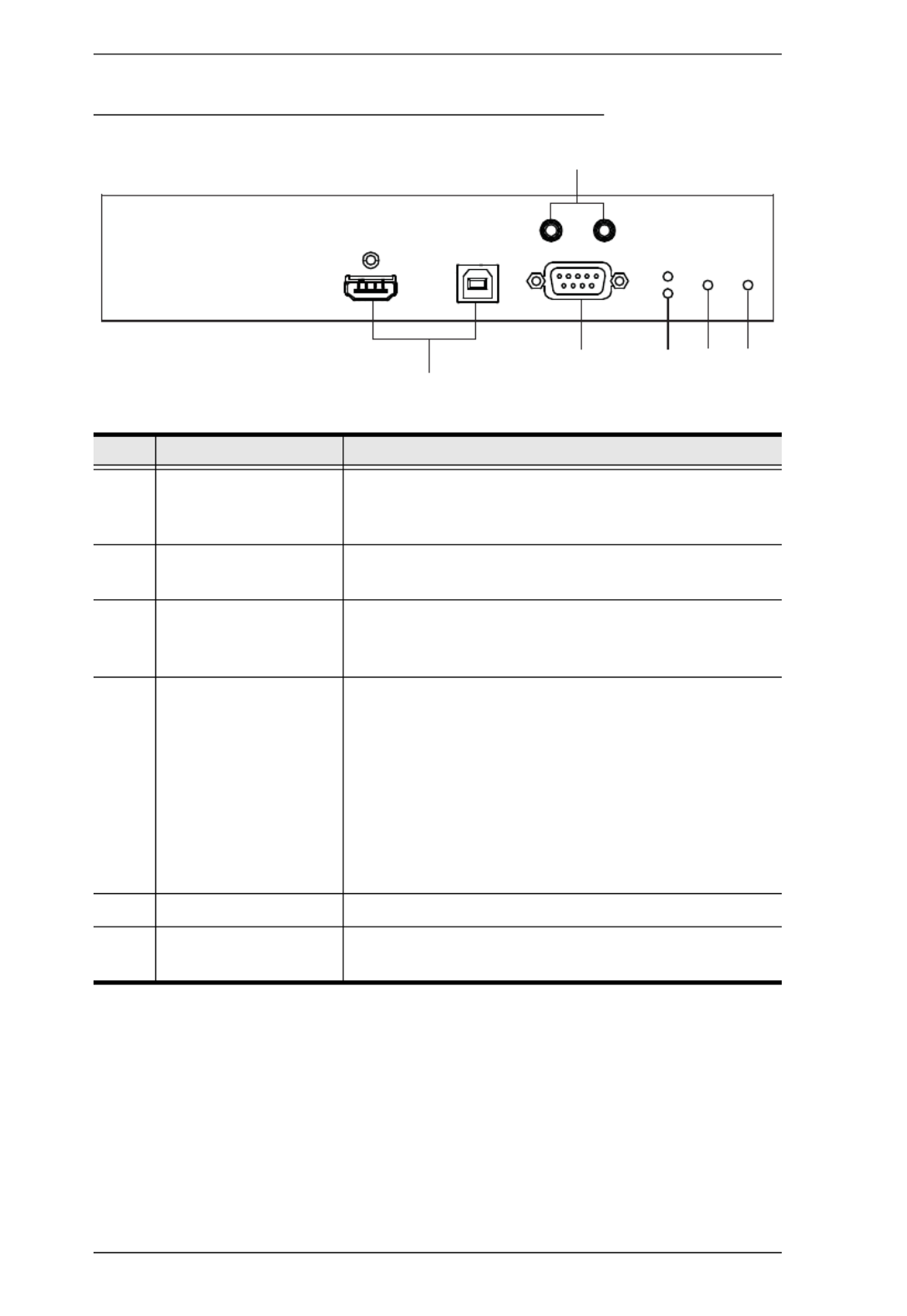
KE6900ST (Transmitter) Front, Rear and Top View
No. Component Description
1 Reset This switch must be pushed with a thin object, such as
the end of a paper clip.
Press and release to reboot the device.
Power off, hold reset then power on the device
while pressing reset to recover from a firmware
upgrade failure.
Press and hold it in for more then three seconds
resets the unit back to its factory default settings.
2 KVM Port The USB KVM cable supplied with the package that links
the Transmitter to the computer plugs into these ports.
3 RS-232 Port This RS-232 serial port is for connecting to the computer
for serial control.
Note: When a LAN connection is detected serial
commands bypass the KE6900ST and are sent across
the network to the receiver. When no LAN connection is
detected serial commands are automatically directed to
the KE6900ST for local configuration and control.
4 LAN Port The cable that connects the unit to the LAN plugs in
here.
5 Power Jack The cable from the DC Power adapter connects here.
45
3
Rear View
21
Front View
6 7
Top View

Chapter 1. Introduction
17
6 LAN LED This LED indicates the network status.
Lights when connected to the LAN and blinks when
the Ethernet connection is active:
Orange: 10 Mbps
Orange + Green: 100 Mbps
Green: 1000 Mbps
Off when not connected to the LAN.
7 Power LED Lights blue to indicate the unit is turned on.
No. Component Description
KVM Over IP Matrix System User Manual
18
KE8950T / KE8952T (Transmitter) Front View
No. Component Description
1 KVM Ports The USB KVM cable supplied with the package that
links the Transmitter to the computer plugs into these
ports.
2 RS-232 Port This RS-232 serial port is for connecting to the
computer for serial control.
3 Remote / Local LED Lights Green to indicate which side of the installation
(Local or Remote) currently has KVM control of the
computer.
4 LAN LED This LED indicates the network status.
Lights when connected to the LAN and blinks when
the Ethernet connection is active:
Orange: 10 Mbps
Orange + Green: 100 Mbps
Green: 1000 Mbps
Off when not connected to the LAN.
5 Power LED Lights blue to indicate the unit is turned on.
6 Audio Ports These mini stereo ports are for the speakers (green)
and microphone (pink).
32
6
4
15

Chapter 1. Introduction
19
KE8950T / KE8952T (Transmitter) Rear View
No. Component Description
1 Power Jack The cable from the DC Power adapter connects here.
2 Function Switch Use this slide switch to set the unit’s mode to:
Auto: Shared (simultaneous) KVM control of the
computer at the Transmitter and Receiver console.
RS-232 Config: The device is ready to be
configured via serial commands through the RS-232
port.
Local: Only the local Transmitter has KVM control
of the computer. The Receiver’s KVM access to the
computer is locked.
3 Reset This switch must be pushed with a thin object, such as
the end of a paper clip.
Press and release to reboot the device.
Power off, hold reset then power on the device
while pressing reset to recover from a firmware
upgrade failure.
Press and hold it in for more then three seconds
resets the unit back to its factory default
settings.
4 RS-232 Port This RS-232 serial port is for connecting to a serial
terminal.
5 Audio Ports These mini stereo ports are for the speakers (green)
and microphone (pink).
6 Console Ports The unit’s USB keyboard and USB mouse plug into
these ports.
7 LAN Port The cable that connects the unit to the LAN plugs in
here.
8 SFP Port The Gigabit Ethernet (GbE) optical fiber cable that
connects the unit to the LAN plugs in here.
1 4
3
2
5
6 7 98

KVM Over IP Matrix System User Manual
20
9 HDMI Output The cable from the local HDMI monitor plugs in here.
No. Component Description

Chapter 1. Introduction
21
KE8950R / KE8952R (Receiver) Front View
No. Component Description
1 Power LED Lights blue to indicate the unit is turned on.
2 LAN LED This LED indicates the network status.
Lights when connected to the LAN and blinks when
the Ethernet connection is active:
Orange: 10 Mbps
Orange + Green: 100 Mbps
Green: 1000 Mbps
Off when not connected to the LAN.
3 Local LED Lights green to Indicate the Transmitter has KVM
access of the computer.
4 Remote LED Lights green to Indicate the Receiver has KVM access
of the computer.
5 Graphics Pushbutton Sets the displays image quality to the highest possible
grade so that images are optimized. This toggle button
turns off the Video Pushbutton option.
Graphics mode is selected by default.
6 OSD Pushbutton Use this pushbutton to open the OSD menu.
7 Video Pushbutton Sets the displays image quality to a grade that is
optimized for video playback. This toggle button turns
off the Graphics Pushbutton option.
8 USB Port Use this port for virtual media or a USB peripheral
device.
Note: When using a USB disk plugged into this port,
see USB Mode, page 97.
143
2
Graphics OSD Video
POWER LAN LOCAL REMOTE
5678

KVM Over IP Matrix System User Manual
22
KE8950R / KE8952R (Receiver) Rear View
No. Component Description
1 Power Jack The cable from the DC Power adapter connects here.
2 Function Switch Use this slide switch to set the unit’s mode:
Extension: Sets the device to use the normal TX to RX
extension mode.
RS-232 Config: The device is ready to be configured via
serial commands through the RS-232 port.
3 Reset This switch must be pushed with a thin object, such as the
end of a paper clip.
Press and release to reboot the device.
Power off, hold reset then power on the device while
pressing reset to recover from a firmware upgrade
failure.
Press and hold it in for more then three seconds
resets the unit back to its factory default settings.
4 RS-232 Port This RS-232 serial port is for connecting to a serial terminal.
5 Audio Ports These mini stereo ports are for the local speakers (green)
and microphone (pink).
6 USB Port Use this port for virtual media or a USB peripheral device.
Note: When using a USB disk plugged into this port, see
USB Mode, page 97.
7 Console Ports The unit’s USB keyboard and USB mouse plug into these
ports. When using a keyboard or mouse with special
functions, see USB Mode, page 97
8 LAN Port The cable that connects the unit to the LAN plugs in here.
9 SFP Port The Gigabit Ethernet (GbE) optical fiber cable that connects
the unit to the LAN plugs in here.
10 HDMI Output The cable from the local HDMI monitor plugs in here.
3
1 2 4
5
7 8
6
9 10

23
Chapter 2
Hardware Setup
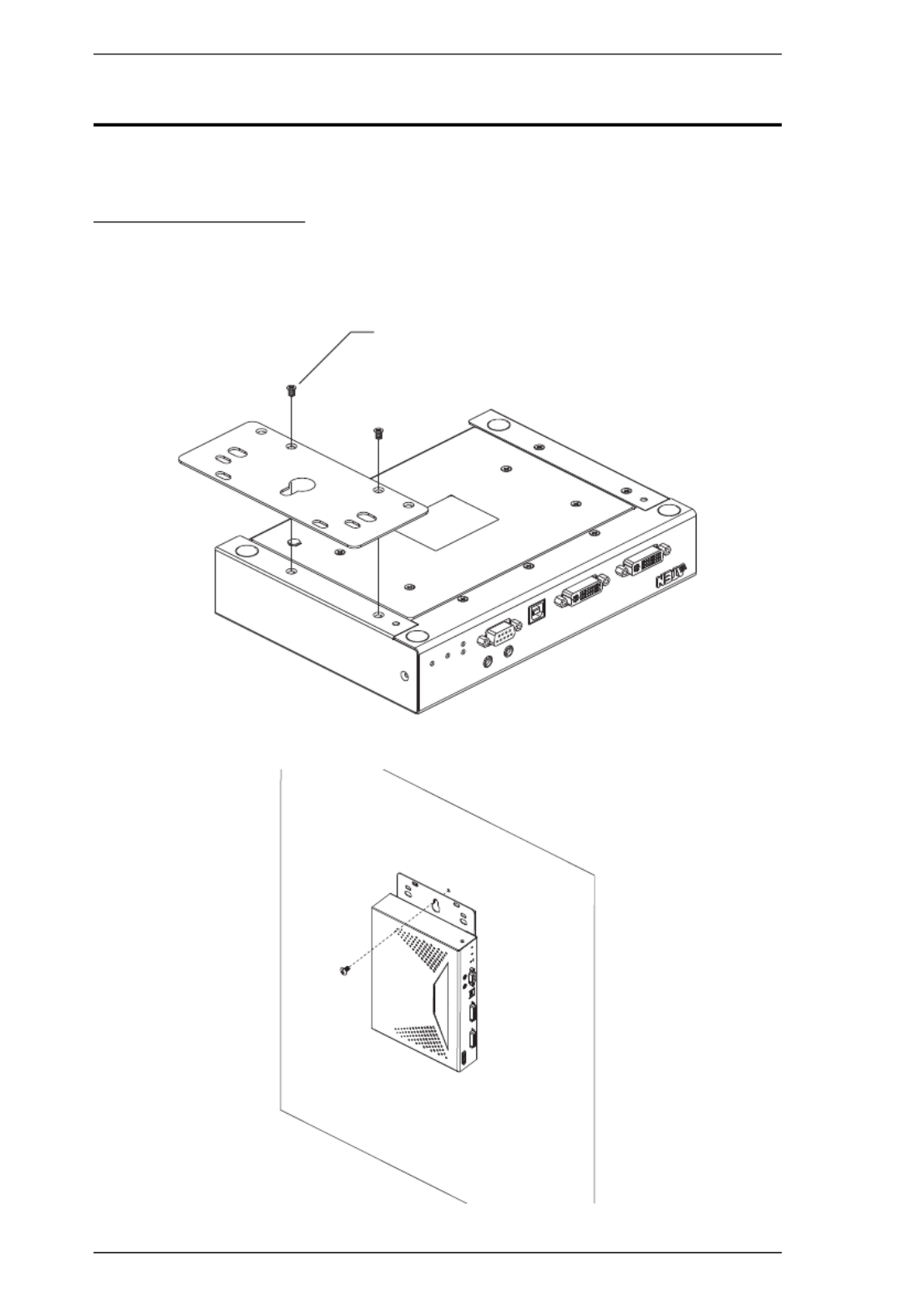
Rack Mounting
For convenience and flexibility, the Transmitter can be mounted on system
racks. To rack mount a unit do the following:
KE6900T/KE6940T
1. Using the screws provided in the Mounting Kit, screw the mounting
bracket into the bottom of the Transmitter as show below:
1. Important safety information regarding the placement of this
device is found on page 207. Please review it before proceeding.
2. Make sure that the power to all devices connected to the
installation is turned off. You must unplug the power cords of any
computers that have the Keyboard Power On function.
Phillips hex head
M3 x 8

KVM Over IP Matrix System User Manual
24
2. Screw the bracket into a convenient location on the rack.
Note: These screws are not provided. We recommend that you use M5 x 12
Phillips Type I cross recessed type screws.

Chapter 2. Hardware Setup
25
KE6900ST
1. Using the screws provided in the Mounting Kit, screw the mounting
bracket into the bottom of the Transmitter as show below:
2. Screw the bracket into a convenient location on the rack.
Note: These screws are not provided. We recommend that you use M5 x 12
Phillips Type I cross recessed type screws.
Phillips hex head
M3 x 8
KVM Over IP Matrix System User Manual
26
Wall Mounting
For convenience the Transmitter can be mounted to a wall.
KE6900T/KE6940T
1. Using the screws provided in the Mounting Kit, screw the mounting
bracket into the bottom of the Transmitter as show below:
2. Use the center hole to screw the bracket to a secure wall surface.
Phillips hex head
M3 x 8

Chapter 2. Hardware Setup
27
KE6900ST
1. Using the screws provided in the Mounting Kit, screw the mounting
bracket into the bottom of the Transmitter as show below:
2. Use the center hole to screw the bracket to a secure wall surface.
Phillips hex head
M3 x 8

KVM Over IP Matrix System User Manual
28
KE6900 Point-to-Point Installation
Setting up the KE6900 / KE6940 system in a point-to-point configuration is
simply a matter of plugging in the cables.
Note: In a point-to-point configuration, no administrator setup is necessary.
Make sure that all the equipment is powered off. Refer to the installation
diagrams on the next two pages and do the following:
1. On the Transmitter side, plug the mouse, keyboard, DVI monitor,
microphone and speakers into the ports on the Console section of the
KE6900T / KE6940T. Each port is marked with an appropriate icon to
indicate itself.*
2. Connect the USB KVM cable provided to the KVM Ports on the front of
the KE6900T / KE6940T.
3. Connect the other end of the USB KVM cable to the keyboard, video,
mouse, speaker and microphone ports on the computer.
4. For control of serial devices, connect the RS-232 serial port on the
Transmitter to a serial port on the computer.
5. Connect a Cat 5e/6 cable to the KE6900T / KE6940T’s LAN port.
6. Plug the power adapter into an AC source; and plug the other end into the
KE6900T / KE6940T’s Power Jack.
7. On the Receiver side, plug the mouse, keyboard, DVI monitor,
microphone, and speakers into the ports on the Console section of the
KE6900R / KE6940R.**
8. Connect the other end of the Cat 5e/6 cable to the KE6900R / KE6940R's
LAN port.
9. Plug the second power adapter into an AC source; and plug the other end
into the KE6900R / KE6940R's Power Jack.
10. Power on the computer.
Note: 1. If installing the KE6940 with two DVI monitors, connect the second
DVI monitor via a DVI cable into the additional ports on the KE6940
and computer.
2. A keyboard or mouse with special functions may need to use the USB
ports for advanced features to work (see , page 97).USB Mode

Chapter 2. Hardware Setup
29
KE6900 Point-to-Point Installation 1 of 2
Note: The diagram above shows the KE6900T and KE6900R. The KE6940
installation is the same except that an additional DVI monitor can be
connected at each end for a dual-view display setup.
KE6900R
6
KE6900T
9
8
Cat 5e/6 cable
5
1
Cat 5e/6 cable
7

KVM Over IP Matrix System User Manual
30
KE6900 Point-to-Point Installation 2 of 2
Note: The serial port on the Transmitter (shown above) connects to the
computer; the serial port on the Receiver (not shown) connects to a
serial device (optional).
2
USB KVM
cable
Local PC
3
4
KE6900T

Chapter 2. Hardware Setup
31
KE8900 Point-to-Point Installation
Setting up the KE8950 / KE8952 system in a point-to-point configuration is
simply a matter of plugging in the cables.
Note: In a point-to-point configuration, no administrator setup is necessary.
Make sure that all the equipment is powered off. Refer to the installation
diagrams on the next two pages and do the following:
1. On the transmitter side, plug the mouse, keyboard, HDMI monitor,
microphone and speakers into the ports on the Console section of the
KE8950T / KE8952T. Each port is marked with an appropriate icon to
indicate its function.
2. Connect the USB HDMI KVM cable provided with this package into the
KVM Ports on the front of the KE8950T / KE8952T.
3. Connect the other end of the USB HDMI KVM cable into the keyboard,
video, mouse, speaker and microphone ports on the computer.
4. For control of serial devices, connect the RS-232 serial port on the
transmitter to a serial port on the computer.
5. Connect a Cat 5e/6 cable to the KE8950T / KE8952T’s LAN port, or a
Gigabit Ethernet (GbE) optical fiber cable to the SFP port.
6. Plug the power adapter into an AC source; then plug the other end into the
KE8950T / KE8952T’s power jack.*
7. On the receiver side, plug the mouse, keyboard, HDMI monitor,
microphone, and speakers into the ports on the Console section of the
KE8950R / KE8952R.
8. Connect the other end of the Cat 5e/6 cable to the KE8950R / KE8952R's
LAN port; or the other end of the Gigabit Ethernet (GbE) optical fiber
cable to the SFP port.
9. Plug the second power adapter into an AC source; then plug the other end
into the KE8950R / KE8952R's power jack.*
10. Power on the computer.
Note: Power adapters are not provided with KE8952 units. Please contact
your ATEN dealer to purchase additional power adapters.

KVM Over IP Matrix System User Manual
32
KE8900 Point-to-Point Installation 1 of 2
Note: Power adapters are not provided with the KE8952. Please contact your
ATEN dealer to purchase additional power adapters, or use the Power
over Ethernet (PoE) feature to supply power to the KE8952.
KE8950R (Rear)
6
KE8950T (Rear)
8
5
1
Cat 5e/6 Cable
7
Optical Fiber Cable
Cat 5e/6 Cable Optical Fiber Cable
9
DC 5V
DC 5V

Chapter 2. Hardware Setup
33
KE8900 Point-to-Point Installation 2 of 2
Note: The serial port on the Transmitter (shown above) connects to the
computer; the serial port on the Receiver (not shown) connects to a
serial device (optional).
2
USB HDMI KVM
Cable
Local PC
3
4
KE8950T (Front)

KVM Over IP Matrix System User Manual
34
KE6900ST Point-to-Point Installation
The KE6900ST DVI KVM over IP Extender Lite is a cost saving alternative
for installations with Transmitters that console or audio don't need a local
transmission but want the connectivity features of advanced KE models.
Setting up the KE6900ST system in a point-to-point configuration is simply a
matter of plugging in the cables. Make sure that all the equipment is powered
off. Refer to the installation diagrams on the next page and do the following:
1. Connect the USB DVI-D KVM Cable (provided with this package) to the
USB and DVI-D ports on the front of the KE6900ST.
2. Connect the other end of the USB DVI-D KVM Cable to USB and DVI
video ports on the computer.
3. For control of serial devices, connect the RS-232 serial port on the
KE6900ST to a serial port on the computer.
4. Plug the power adapter (provided with this package) into an AC source;
and plug the other end into the KE6900ST Power Jack.
5. Connect a Cat 5e/6 cable to the KE6900ST’s LAN port.
6. Connect the other end of the Cat 5e/6 cable to the KE69x0R's* LAN port.
7. On the Receiver side, plug the mouse, keyboard and DVI monitor into the
ports on the Console section of the KE69x0R.*
8. Plug the second power adapter into an AC source; and plug the other end
into the KE69x0R's Power Jack.
9. Power on the computer.
Note: KE69x0R units are required and sold separately.
Setting up a LAN Installation
Setting up the KE6900ST on a network allows point-to-point, point-to-
multipoint, and multipoint-to-multipoint computer to console operation by
connecting multiple KE69x0 devices on the same TCP/IP LAN. To setup a
LAN installation, simply connect the Cat 5e/6 cable (in step 5 above) to the
network instead of directly between two KE69x0 devices and see KE6900 LAN
Installation, page 36 for details.

Chapter 2. Hardware Setup
35
1
USB KVM
cable
Local PC
3
2
KE6900ST (Front) KE6900ST (Rear)
KE6900R
5
Cat 5e/5 cable
4
6
8
7

KVM Over IP Matrix System User Manual
36
KE6900 LAN Installation
Setting up the units on a network allows point-to-point, point-to-multipoint,
and multipoint-to-multipoint computer to console operation by connecting
multiple KE6900 / KE6900ST / KE6940 devices on the same TCP/IP LAN.
Prior to setup we recommended laying out the plans for your KE installation
using our performance guide (see Keys to Network Performance, page 228).
Note: 1. The units are preconfigured with factory-default network settings. If
you install only one set of KE Series units, you do not need to change
these default network settings. See Default IP Addresses, page 45, for
further details.
2. In a network setup with multiple units, each Transmitter and Receiver
must be configured with a unique IP address. See Network
Configuration, page 44, for further details.
3. We recommended using 1000Mbps Gigabit Ethernet switches (wire
speeds, non-blocking with 1Gbps/1.5Mpps performance per port)
between KE Series devices installed on different LAN segments. 10/
100Mbps switches might cause poor performance.
4. In multipoint configurations, the IGMP and flow control function of
your network switches/hubs must be enabled to avoid the
deterioration of data throughput. To ensure functionality use a layer 3
switch that supports IGMP queries.
5. If your network uses cascaded switches, please check to ensure the
data throughput is sufficient.
6. To get the best performance, we suggest creating a private network
for KE devices, as they are bandwidth-intensive devices.
Make sure that all the equipment is powered off. Refer to the installation
diagram on the following page, and do the following:
1. On the Transmitter side, plug the mouse, keyboard, DVI monitor,
microphone and speakers into the ports on the Console section of the
KE6900T / KE6940T.* Each port is marked with an appropriate icon to
indicate itself.
2. Connect the USB KVM cable provided to the KVM Ports on the front of
the KE6900T / KE6940T.
3. Connect the other end of the USB KVM cable to the keyboard, video,
mouse, speaker and microphone ports on the computer.

Chapter 2. Hardware Setup
37
4. For control of serial devices, connect the RS-232 serial port on the
Transmitter to a serial port on the computer.
5. Use a Cat 5e/6 cable to connect the KE6900T / KE6940T’s LAN port to
the local area TCP/IP network.
6. Plug the power adapter into an AC source; and plug the other end into the
KE6900T / KE6940T’s Power Jack.
7. On the Receiver side, plug the mouse, keyboard, DVI monitor,
microphone, and speakers into the ports on the Console section of the
KE6900R / KE6940R.**
8. Use a Cat 5e/6 cable to connect the KE6900R / KE6940R’s LAN port to
the local area TCP/IP network.
9. Plug the second power adapter into an AC source; and plug the other end
into the KE6900R / KE6940R's Power Jack.
10. Use the OSD on the Receiver to configure the network settings for both
devices (See Network Configuration, page 44).
11. Repeat these steps for each Transmitter and Receiver you wish to install on
the network.
12. Power on the computer(s).
Note: 1. If installing the KE6940 with two DVI monitors, connect the second
DVI monitor via a DVI cable into the additional ports on the KE6940
and computer.
2. A keyboard or mouse with special functions may need to use the USB
ports for advanced features to work (see USB Mode, page 97).

KVM Over IP Matrix System User Manual
38
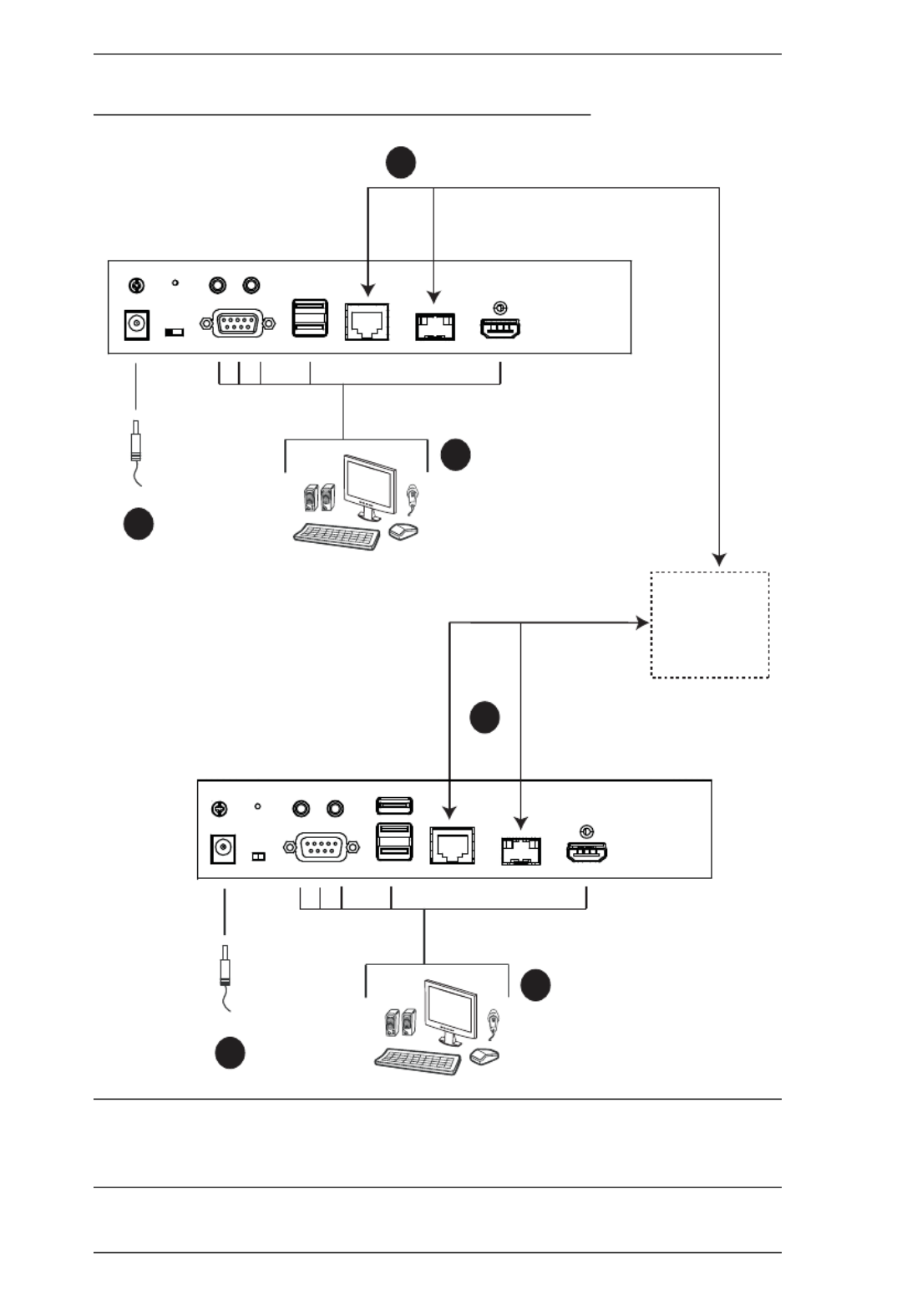
KE6900 Network Installation Diagram 1 of 2
Note: The diagram above shows the KE6900T and KE6900R. The KE6940
installation is the same except that an additional DVI monitor can be
connected at each end for a dual-view display setup.
6
KE6900T
5
1
Cat 5e/6 cable
KE6900R
9
8
Cat 5e/6 cable
7
TCP/IP
LAN

Chapter 2. Hardware Setup
39
KE6900 Network Installation Diagram 2 of 2
Note: The serial port on the Transmitter (shown above) connects to the
computer; the serial port on the Receiver (not shown) connects to a
serial device (optional).
2
USB KVM
cable
Local PC
3
4
KE6900T

KVM Over IP Matrix System User Manual
40
KE8950 LAN Installation
Setting up the units on a network allows point-to-point, point-to-multipoint,
and multipoint-to-multipoint computer to console operation by connecting
multiple KE8950 / KE8952 devices on the same TCP/IP LAN. Prior to setup
we recommended laying out the plans for your KE installation using our
performance guide (see Keys to Network Performance, page 228).
Note: 1. The units are preconfigured with factory-default network settings. If
you install only one set of KE Series units, you do not need to change
these default network settings. See Default IP Addresses, page 45, for
further details.
2. In a network setup with multiple units, each Transmitter and Receiver
must be configured with a unique IP address. See Network
Configuration, page 44, for further details.
3. We recommended using 1000Mbps Gigabit Ethernet switches (wire
speeds, non-blocking with 1Gbps/1.5Mpps performance per port)
between KE Series devices installed on different LAN segments. 10/
100Mbps switches might cause poor performance.
4. In multipoint configurations, the IGMP and flow control function of
your network switches/hubs must be enabled to avoid the
deterioration of data throughput. To ensure functionality use a layer 3
switch that supports IGMP queries.
5. If your network uses cascaded switches, please check to ensure the
data throughput is sufficient.
6. To get the best performance, we suggest creating a private network
for KE devices, as they are bandwidth-intensive devices.
Make sure that all the equipment is powered off. Refer to the installation
diagram on the following page, and do the following:
1. On the Transmitter side, plug the mouse, keyboard, HDMI monitor,
microphone and speakers into the ports on the Console section of the
KE8950T / KE8952T. Each port is marked with an appropriate icon to
indicate itself.
2. Connect the USB KVM cable provided to the KVM Ports on the front of
the KE8950T / KE8952T.
3. Connect the other end of the USB KVM cable to the keyboard, video,
mouse, speaker and microphone ports on the computer.

Chapter 2. Hardware Setup
41
4. For control of serial devices, connect the RS-232 serial port on the
Transmitter to a serial port on the computer.
5. Connect a Cat 5e/6 cable to the LAN port, or a Gigabit Ethernet (GbE)
optical fiber cable to the SFP port to connect the KE8950T / KE8952T to
the local area TCP/IP network.*
6. Plug the power adapter into an AC source; and plug the other end into the
KE8950T / KE8952T’s Power Jack.**
7. On the Receiver side, plug the mouse, keyboard, HDMI monitor,
microphone, and speakers into the ports on the Console section of the
KE8950R / KE8952R.***
8. Connect a Cat 5e/6 cable to the LAN port, or a Gigabit Ethernet (GbE)
optical fiber cable to the SFP port to connect the KE8950R / KE8952R to
the local area TCP/IP network.*
9. Plug the power adapter into an AC source; and plug the other end into the
KE8950R / KE8952R's Power Jack.**
10. Use the OSD on the Receiver to configure the network settings for both
devices (See Network Configuration, page 44).
11. Repeat these steps for each Transmitter and Receiver you wish to install on
the network.
12. Power on the computer(s).
Note: 1. The KE8952’s LAN port provides Power over Ethernet (PoE)
functionality which supplies power to the unit when connected to a
compatible PoE network switch.
2. Power adapters are not provided with KE8952 units. Please contact
your ATEN dealer to purchase additional power adapters, or use the
Power over Ethernet (PoE) feature to supply power to KE8952 units.
3. A keyboard or mouse with special functions may need to use the USB
ports for advanced features to work (see USB Mode, page 97).
KVM Over IP Matrix System User Manual
42
KE8950 Network Installation Diagram 1 of 2
Note: Power adapters are not provided with KE8952 units. Please contact
your ATEN dealer to purchase additional power adapters, or use the
Power over Ethernet (PoE) feature to supply power to KE8952 units.
KE8950R (Rear)
6
KE8950T (Rear)
8
5
1
Cat 5e/6 Cable
7
Optical Fiber Cable
Cat 5e/6 Cable Optical Fiber Cable
9
DC 5V
DC 5V
TCP/IP
LAN

Chapter 2. Hardware Setup
43
KE8950 Network Installation Diagram 2 of 2
Note: The serial port on the Transmitter (shown above) connects to the
computer; the serial port on the Receiver (not shown) connects to a
serial device (optional).
2
USB HDMI KVM
Cable
Local PC
3
4
KE8950T (Front)

KVM Over IP Matrix System User Manual
44
Network Configuration
This section provides instructions to configure the network settings with a
fixed IP address, subnet mask, and default gateway. To use the IP Installer to
configure the IP address, see IP Installer, page 222.
Note: 1. Both devices are preconfigured with factory-default network settings.
If you install only one set of KE Series units, you do not need to
change these default network settings. See Default IP Addresses,
page 45, for further details.
2. In a network setup with multiple units, each transmitter and receiver
must be configured with a unique IP address. See Network
Configuration, page 44, for further details.
3. We recommended using 1000Mbps Gigabit Ethernet switches (wire
speeds, non-blocking with 1Gbps/1.5Mpps performance per port)
between devices installed on different LAN segments. 10/100Mbps
switches might cause poor performance.
4. In multipoint configurations, the IGMP and flow control function of
your network switches/hubs must be enabled to avoid the
deterioration of data throughput. To ensure functionality use a layer 3
switch that supports IGMP queries.
5. If your network uses cascaded switches, please check to ensure the
data throughput is sufficient.
6. To get the best performance, we suggest creating a private network
for KE device, as they are bandwidth-intensive devices.
To configure the network settings, do the following:
1. Setup the hardware and connect the Transmitter and Receiver to the local
area network (see KE6900 LAN Installation, page 36, or KE8950 LAN
Installation, page 40).
2. From the Receiver, tap the Scroll Lock key twice to invoke the OSD.
3. Select the User Station or Transmitter from the sidebar menu.
4. Enter the password and click Configure.
The default password is: .
5. From the Network tab select Set IP address manually and enter the
following:

Chapter 2. Hardware Setup
45
IP Address– sets the IP address for the KE device. Key in a valid
unique IP address.
Note: See Default IP Addresses, page 45, for the preconfigured
factory-default settings.
Subnet Mask – sets the subnet mask for the KE device. Key in a valid
subnet mask value.
Note: The default setting is 255.255.255.0
Default Gateway– sets the default gateway for the KE device. Key in a
valid default gateway.
6. Click Save.
Exit OSD
To exit the OSD, press [Esc] on the keyboard, click Logout; tap the Scroll
Lock key twice; or return to the OSD main page and press the front panel OSD
pushbutton (Receiver only).
At this point the Receiver can connect to the Transmitter to access the remote
computer (see Connecting, page 60 for instructions).
Default IP Addresses
The preconfigured factory-default IP addresses for the KE Series devices are
as follows:
Transmitters –
Receivers –

KVM Over IP Matrix System User Manual
46
KE I/O Ports
The following table provides the I/O port use of KE Series devices.
Device Port Number
KE Management (TCP) HTTP 8080
HTTPS 8443
Device TCP 9110
CLI 9111
Redundancy 9120
Database Service 1527
KE Management (UDP) Port 9110
Broadcast 9000
KE TX/RX Device (TCP) Manager 9110
Service 9000
Telnet 23
SSH 22
KE TX Device (TCP) VM 9001
vUSB 9002
Serial 9003
USB Access Mode 9009
KE RX Device (TCP) CLI 9130
KE TX/RX Device (UDP) Manager 9110
Service 9000
Array Mode 9120
Video 0xFE00(65024) - 0xFE03(65027)
Audio 0xFE04(65028) - 0xFE05(65029)

47
Chapter 3
OSD Operation
Overview
This chapter provides instructions to configure and operate KE Series devices
using the local On Screen Display (OSD). To configure the network settings
with the OSD, see Network Configuration, page 44.
LED Display
Both the Transmitter and Receiver have front panel LEDs to indicate their
operating and power status, as explained in the table below:
LED Indication
LAN This LED indicates the network status.
Lights when connected to the LAN and blinks when the Ethernet
connection is active:
Orange: 10 Mbps
Orange + Green: 100 Mbps
Green: 1000 Mbps
Off when not connected to the LAN.
Power Lights blue when the unit is powered on.
OFF when power is off.
Local Lights green to Indicate the Transmitter has KVM focus of the
computer
Remote Lights green to Indicate the Receiver has KVM focus of the
computer.

Chapter 3. OSD Operation
49
OSD Interface
After you invoke the OSD, the main page appears:
Note: A password is required to enter the OSD. The default password is:
password. For security purposes, we recommend you change this to
something unique.
The OSD components are described in the table, below:
No. Item Description
1 User Station
(Receiver)
Select this radio button, enter a password, and click
Configure to enter the User Station Configuration screen.
2 Transmitter Select this radio button, enter a password, and click
Configure to enter the Transmitter Configuration screen.
Note: Receiver must first discover the transmitter over the
network for this option to be available.
3 User Preferences Select this radio button, enter a password, and click
Configure to enter the User Preferences screen.
4 About About provides information regarding the OSD version.
5 Password Input the OSD password and click Configure to enter the
selected configuration screen. See note for password.
6 Configure After entering a password, click Configure to enter the
selected configuration screen.
7 Back to Video Clicking this button exits the OSD and returns you to the
computer’s video display.

KVM Over IP Matrix System User Manual
50
User Station Configuration
When you select the User Station radio button and click Configure to login,
the Network tab appears:
Network
The Network tab allows you to configure the User Station’s IP address settings:
After entering the information, click Save.
Item Description
IP Installer The IP Installer is an external Windows-based utility for
assigning an IP address to the device. Click one of the radio
buttons to select Enable, View Only, or Disable for the IP
Installer utility. See IP Installer, page 222 for instructions.
Note: For security, we strongly recommend that you set this to
View Only or Disable after each use.
Network
Configuration
For dynamic IP address assignment (DHCP), select the Obtain
IP address automatically radio button.
To specify a fixed IP Address, Subnet Mask, and Default
Gateway select the Set IP address manually radio button and
fill in the fields with values appropriate for your network.
For help configuring network settings with the OSD,
See Network Configuration, page 44.

Chapter 3. OSD Operation
51
Properties
The Properties tab allows you to configure the User Station’s settings:
Item Description
Mode Select Extender mode for simple one-to-one (Transmitter to
User Station) setups that are managed with the Receiver’s OSD
menu.
Select Matrix mode to manage devices and connections from
the KE Management web GUI. This mode is for advanced
administration of Transmitter to User Station connections.
(See Channel Connections, page 110)
Properties If you selected Extender mode (above) set the Transmitter IP
address for the User Station’s Video, Audio, USB, and RS232
source signals.
If you selected Matrix mode (above) the will be Properties
grayed out. Use Channels to configure the Transmitter
connections. (See Channel Connections, page 110)
RS232 Settings Configure the serial device settings for the User Station. The
default settings are:
Baud Rate: 9600
Parity: None
Data Bits: 8 bits
Stop bits: 1 bit
Flow Control: None

KVM Over IP Matrix System User Manual
52
After entering the information, click Save.
Enable Media Select which type of media the User Station can stream from
Transmitters: Video, Audio, USB, and RS232. For KE8950
Series models, use the radio button to set the source of the
audio signal: HDMI, Analog, or Both.
Manager
Address
Set the IP address and Port number of the computer running
the KE Management software. The default port number is 9110.
Beeper Check this box to allow the User Station to beep when
configuration changes are made to it.
Touch Screen
Calibration
Use this button to calibrate the surface of a USB touch screen
connected to the unit. When the calibration screen appears,
touch the flashing + symbol at each corner until the process is
complete.
USB Mode Select the type of USB device you will connect to the USB ports:
Virtual Media: Only select this option if you are plugging a USB
disk into the USB ports. This will give you the highest data
transfer speeds but will not allow other USB devices plugged
into the USB ports to work. When user stations connected to the
same transmitter mount or unmount USB disk drives, the
keyboard and mouse operations will experience a brief delay.
Transmitters can support up to 12 virtual media connections at
the same time (keyboard/mouse included).
Generic USB device: Use this option to plug USB peripherals
into the USB ports. This option also allows a keyboard and
mouse with special functions to plug into the USB ports for
console use. Use this only if the special functions of the
keyboard or mouse are required but do not work when plugged
into the console ports. When the keyboard and mouse are
plugged into the USB ports, they will not work within the OSD
menus. To work within the OSD menus, the keyboard and
mouse must be plugged into the console ports. KE6900ST
transmitters do not support the Generic USB Device mode. In
this mode, KE6900/KE6940 transmitters supports up to 2 USB
connections; and KE8950/KE8952 transmitters support up to 5
USB connections (keyboard/mouse excluded).
Encryption: Check this box to encrypt USB drives plugged into
the USB ports.
User Station
Keyboard
Use the Keyboard Country Code drop-down menu to select the
User Station’s language keyboard for use in the OSD.
Item Description

Chapter 3. OSD Operation
53
System
The System tab allows you to configure the User Station’s general settings:
After entering the information, click Save.
Item Description
Device
Information
Enter the Name, Location, and of the User Description
Station. It also displays the , IP Address MAC Address, F/W
Version, Serial Number, and Model Number of the User Station.
Reboot Check the box and click Reboot to reset the User Station’s
settings back to the factory default. All custom settings will be
lost.
User Station
Password
Change
Check Enable to require a password for access to the User
Station’s OSD configuration screen. Enter the Old Password,
enter a New Password, and confirm the new password in the
Confirm Password box.
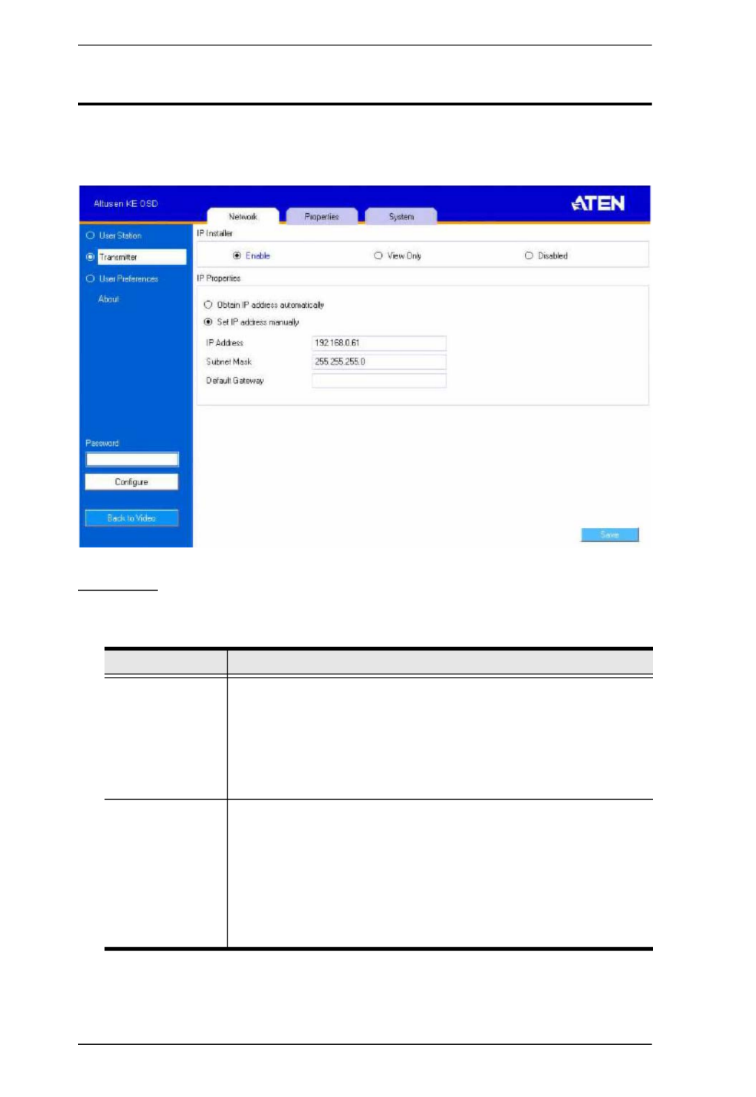
KVM Over IP Matrix System User Manual
54
Transmitter Configuration
When you select the Transmitter radio button and click Configure to login, the
Network tab appears:
Network
The Network tab allows you to configure the Transmitter’s IP address settings:
After entering the information, click Save.
Item Description
IP Installer The IP Installer is an external Windows-based utility for
assigning an IP address to the device. Click one of the radio
buttons to select Enable, View Only, or Disable for the IP
Installer utility. See IP Installer, page 222 for instructions.
Note: For security, we strongly recommend that you set this to
View Only or Disable after each use.
Network
Configuration
For dynamic IP address assignment (DHCP), select the Obtain
IP address automatically radio button.
To specify a fixed IP Address, Subnet Mask, and Default
Gateway select the Set IP address manually radio button and
fill in the fields with values appropriate for your network.
For help configuring network settings with the OSD,
See Network Configuration, page 44.
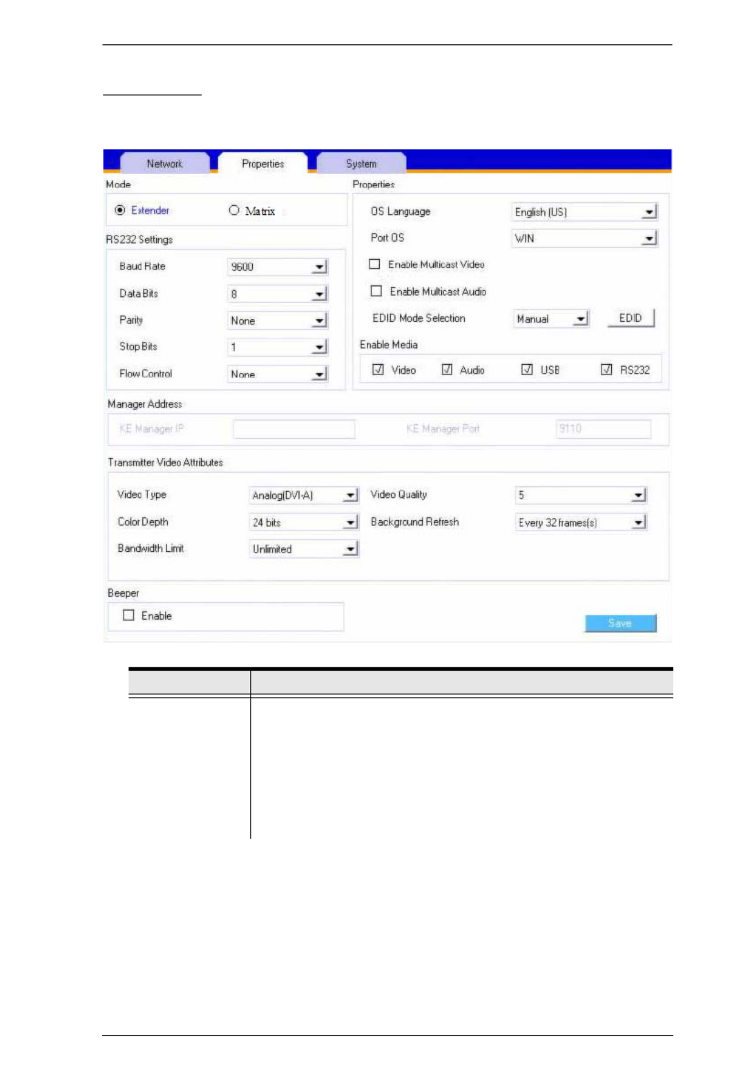
Chapter 3. OSD Operation
55
Properties
The Properties tab allows you to configure the Transmitter’s extender settings:
Item Description
Mode Select Extender mode for simple one-to-one (Transmitter to
User Station) setups that are managed with the Receiver’s OSD
menu.
Select Matrix mode to manage devices and connections from
the KE Management web GUI. This mode is for advanced
administration of Transmitter to User Station connections.
(See Channel Connections, page 110)

KVM Over IP Matrix System User Manual
56
Properties Port OS: Use the drop-down menu to select the operating
system of the computer connected to the Transmitter.
OS Language: Use the drop-down menu to select the
operating system language of the computer connected to the
Transmitter.
Enable Multicast Video: Check this box to allow a broadcast of
the Transmitter’s video signal to be sent out to multiple User
Stations.
Enable Multicast Audio: Check this box to allow a broadcast
of the Transmitter’s audio signal to be sent out to multiple User
Stations.
EDID Mode Selection: EDID contains a display's basic
information and is used by the source device to utilize the best
resolution across different monitors. Select how you want the
source device to acquire the display's EDID:
Default: EDID is set to the default ATEN configuration. This
setting must be used when connecting KE6900 devices to
KE8950 devices.
Auto: Checks the EDID of all connected displays and uses
the best resolution for all displays.
Manual: Manually set the EDID configuration from the
Connections Page (see page 61).
Remix: Checks the EDID of all connected displays and the
source device uses the best common resolution for all
displays.
Enable Media Select which type of media the Transmitter can stream to User
Stations: Video, Audio, USB, and RS232.
RS232 Settings Configure the serial device settings for the Transmitter. The
default settings are:
Baud Rate: 9600
Parity: None
Data Bits: 8 bits
Stop bits: 1 bit
Flow Control: None
Manager
Address
Set the IP address and Port number of the computer running
the KE Management software. The default port number is 9110.
Item Description

Chapter 3. OSD Operation
57
After entering the information, click Save.
Transmitter
Video Attributes
To set the Transmitter’s video settings:
Video Type: Select the DVI video connector being used by the
display: Digital (DVI-D) or Digital (DVI-I). This option is available
for KE6900 units and will be grayed out for other models.
Color Depth: Select the number of bits to use for the color
depth: 24, 16, or 8. This is the number of bits used to describe
the color of a single pixel. A bit depth determines the number of
colors that can be displayed at one time.
Bandwidth Limit: Select the maximum bandwidth that the
Transmitter can use to transmit video over the network. A lower
bandwidth setting transmits lower quality video; a higher
bandwidth setting sends higher quality video but this can affect
network speed.
Video Quality: Select the video quality to use. 5 is the highest
video quality, and 1 is the lowest video quality. Options are: 1~5.
Background Refresh: Sets how often the Transmitter
refreshes the background image on the connected display.
Options are to refresh every 256,128, 64, 32,16, or 0 frames.
Beeper Check this box to allow the device to beep every time a
configuration change is made.
Occupy Timeout Set a time threshold for devices whose Access Mode has been
set to Occupy (see Allowed Access Mode, page 144). If there is
no activity from the User Station occupying the port for the
amount of time set here, the User Station is timed out and the
port is released. The first User Station to send keyboard or
mouse input after the port has been released gets to occupy the
port. Input a value from 1 to 240 seconds.
Item Description

KVM Over IP Matrix System User Manual
58
System
The System tab allows you to configure the Transmitter’s general settings:
After entering the information, click Save.
Item Description
Device
Information
Enter the Name, Location, and Description of the Transmitter.
It also displays the IP Address, MAC Address, F/W Version,
Serial Number, and of the Transmitter. Model Number
Reboot Check the box and click Reboot to reset the Transmitter’s
settings back to the factory default. All custom settings will be
lost.
Transmitter
Password
Change
Check Enable to require a password for access to the
Transmitter’s OSD configuration screen. Enter the Old
Password, enter a New Password, and confirm the new
password in the Confirm Password box.

Chapter 3. OSD Operation
59
User Preferences
When you select the User Preferences radio button and click Configure to
login, the configuration screen appears:
When you have made your choices, Click Save.
Item Description
User Password
Change
This section allows you to change the OSD password:
1. Key in the old password in the Old password field.
2. Key in the new password in the New password field.
3. Key in the new password again in the Confirm password
field.
OSD Language Click the drop-down menu to select the language you want to
use for OSD sessions. Choices are: English, Chinese
(Simplified), Chinese (Traditional), Japanese, Korean, Dutch,
French, Spanish, Portuguese, and Russian.
OSD Hotkey Select the hotkey combination to invoke the OSD screen.
Logout Timeout If there is no user input for the amount of time set with this
function, the user is automatically logged out of the OSD. A
login is necessary before the OSD can be accessed again.
Screen Blanker Set how many minutes the OSD waits when a session is idle
before turning off the display.

KVM Over IP Matrix System User Manual
60
Connecting
If the User Station is set to Extender mode, the video screen of the remote
computer will appear automatically when you exit the OSD (press Esc to exit).
In Matrix mode you will see the System Login screen, which provides access
to the Connection Page by entering a username and password:
Note: 1. The administrator account can be used to log in for the first time.
Username: administrator | Password: password. For security
purposes, we recommend you change this to something unique (see
User Management, page 127).
2. If the User Station does not require a login, click Login to system (see
Login Required, page 96).
3. For information about Extender and Desktop/Matrix modes see
Mode, page 51.
After you login the Connection Page appears, as shown on the next page.

Chapter 3. OSD Operation
61
Connections Page
After you have successfully logged in the Connection Page appears:
List Mode
The Connection Page components are described in the table, below:
No. Item Description
1 Channel Name Lists the Channel connections available for the User
Station. A Channel is a defined connection to
Transmitters, created in the Device Management tab
of the KE Management (see Channels, page 111).
2 Description This field provides a description of the Channel,
entered when it was created.

KVM Over IP Matrix System User Manual
62
3 Connect To connect the User Station to a Channel, click the
access type:
Exclusive: The first User Station to access the
Channel has exclusive control over the Channel. No
other User Stations can view the Channel. The
Timeout function does not apply to this setting.
Occupy: The first User Station to access the
Channel has control over the Channel. However,
additional User Stations may view the Channel's
video display. If the User Station controlling the
Channel is inactive for longer than the time set in the
Timeout box, control is transferred to the first User
Station to move the mouse or strike the keyboard.
Share: Can simultaneously share control over the
Channel. Input from the User Stations is placed in a
queue and executed chronologically.
View Only: User Station connects with view only
access to the Channels video display.
4 Next Arrow Use these two buttons to navigate to the next page
or to the end of the list if there are more Channels
available than can be seen on the page.
5 Previous Arrow Use these two buttons to navigate to the previous
page or to the beginning of the list if there are more
Channels available than can be seen on the page.
6 Favorites / All Click Favorites to list only the Channels marked as
favorites. Click All to list all Channels. Channels
marked as favorites appear with a heart icon.
To add/remove a Favorite, select a Channel and
then right click with the mouse to select Add to
Favorite or Remove from Favorite.
7 Array Mode Click to view the Channel connections with a video
preview of each source. The list will be shown in
groups of six at a time. The Array Mode is discussed
on page 63.
8 List Mode Click to view the Channel connections in a list that
can be sorted by name or with favorites listed first.
Click the Channel Name heading to change the sort.
9 Manual EDID If the EDID Model Selection on the Properties tab is
set to Manual, the Manual EDID button appears
here. Click Manual EDID to adjust the EDID setting
locally. To set the EDID Mode to Manual, see
Properties, page 56.
10 Logout Click this button to log out of the Connection Page.
11 Go to Configuration
Window
Click this button to return to the main OSD screen.
No. Item Description

Chapter 3. OSD Operation
63
Array Mode
In Array Mode the screen is divided into a grid of panels, with each panel
showing the video display of a particular Channel. Right-click a panel and
select a mode to connect: E O S V: Exclusive, : Occupy, : Share, : View Only,
X: Exit.
No. Item Description
1 Next Arrow Use these two buttons to navigate to the next page
or to the end of the list if there are more Channels
available than can be seen on the page.
2 Previous Arrow Use these two buttons to navigate to the previous
page or to the beginning of the list if there are more
Channels available than can be seen on the page.
3 Grid Selection Select a range for how many Channels you want to
display. Options are: 2x2, 3x3, 4x4, 5x5, and 6x6.
4 Favorites Click Favorites to list only the Channels marked as
favorites. Click All to list all Channels.
To add/remove a Favorite, go to List Mode, select a
Channel and then right click with the mouse to select
Add to Favorite or Remove from Favorite.

KVM Over IP Matrix System User Manual
64
5 List Mode Click to view the Channel connections in a list that
can be sorted by name or with favorites listed first.
Click the Channel Name heading to change the sort.
List Mode is discussed on page 62.
6 Logout Click this button to log out of the Connection Page.
10 Configure Click this button to return to the main OSD screen.
No. Item Description

Chapter 3. OSD Operation
65
Profile / Video Wall Page
Click the Profile / Video Wall Page tab and the following screen appears:
The Profile /Video Wall Page components are described in the table, below:
No. Item Description
1 Name Lists the Profiles and Video Walls available. Profiles
/ Video Walls give User Stations access to Channels
and allow you to push the connection.
2 Description The field provides a description of the Profile/Video
Wall that was entered when it was created.
3 Connect Click Connect and the User Station will connect with
the settings of that Profile or Video Wall (see
Profiles, page 117 or Video Wall, page 121).
4 Disconnect Click Disconnect to end the current Profile or Video
Wall connection.
5 Next Arrow Use these two buttons to navigate to the next page
or to the end of the list if there are more Profiles/
Video Walls available than can be seen on the page.
6 Previous Arrow Use these two buttons to navigate to the previous
page or to the beginning of the list if there are more
Profiles/Video Walls available than can be seen on
the page.

KVM Over IP Matrix System User Manual
66
7 Video Wall Click to view a list of available Video Wall
connections. Appears when the Profile button has
been clicked.
8 Profile Click to view a list of available Profile connections.
Appears when the Video Wall button has been
clicked.
9 Logout Click this button to log out of the Connection Page.
10 Go to Configuration
Window
Click this button to return to the main OSD screen.
No. Item Description

Chapter 3. OSD Operation
67
Push Content
Push Content allows you to push the User Stations current connection to
another User Station’s console – allowing both the share access to the
computer. Click the Push Content tab and the following screen appears:
The Push Content Page components are described in the table, below:
No. Item Description
1 User Station Name Lists the User Station Name(s) that can be selected
to push the connection from the local User Station.
2 Description The field provides a description of the User Station
that was entered when it was created.
3 Connect Click Push Content to push the User Station’s
connection to the selected User Station’s console.
The local User Station's connection will appear on
the User Station that it was pushed to and both will
share access to the computer. The access mode
selected by the local User Station will determine how
access is shared (see Allowed Access Mode,
page 144 for details).
5 Next Arrow Use these two buttons to navigate to the next page
or to the end of the list if there are more choices
available than can be seen on the page.
6 Previous Arrow Use these two buttons to navigate to the previous
page or to the beginning of the list if there are more
choices available than can be seen on the page.

KVM Over IP Matrix System User Manual
68
9 Logout Click this button to log out of the Connection Page.
10 Go to Configuration
Window
Click this button to return to the main OSD screen.
No. Item Description

Chapter 3. OSD Operation
69
Pull Content
Pull Content allows you to pull a User Station’s Channel connection to the
local User Station’s console – allowing both to share access to the computer.
Click the Pull Content tab and the following screen appears:
The Pull Content Page components are described in the table, below:
No. Item Description
1 User Station Name Lists the User Station Name(s) currently connected
to the Channel listed under Channel Status.
2 Channel Status Lists the name, description and access type of each
available Channel connection.
3 Connect Click Pull Content and the User Station will pull the
Channel connection to the local console and use the
access mode displayed under Channel Status.
5 Next Arrow Use these two buttons to navigate to the next page
or to the end of the list if there are more choices
available than can be seen on the page.
6 Previous Arrow Use these two buttons to navigate to the previous
page or to the beginning of the list if there are more
choices available than can be seen on the page.
9 Logout Click this button to log out of the Connection Page.

KVM Over IP Matrix System User Manual
70
10 Go to Configuration
Window
Click this button to return to the main OSD screen.
No. Item Description

71
Chapter 4
Software Installation
Overview
The KE Management Software is a browser based GUI that provides
management of KE Series devices over a network. You can download the KE
Management Lite version which is free and manages up to 8 KE devices, or
purchase a full version of the KE Management Software. To purchase the full
version contact your local authorized ATEN dealer. To download the free KE
Management Lite Software, use the instructions below.
Download - Trial Version
To download the KE Management Lite software, do the following:
1. Visit our website and click Support → Go to ATEN eService.
2. Create an account and Sign In to ATEN eService.
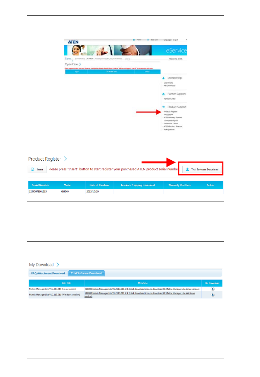
KVM Over IP Matrix System User Manual
72
3. Register the KE device(s) you have purchased.
4. After you have registered the KE device(s), click Trial Software
Download.
Note: The trial version or “KE Management Lite” includes full functions to
setup and configure up to 8 KE Series (transmitter/receiver) devices. The KE
Management Lite version will never expire. If you would like to purchase the
official full version of the KE Management software, please contact your
ATEN reseller and see page 76.
5. Click the software version you would like to download, then click Save.
6. Unzip the KE_Management_Lite.zip file and double click the *.exe file to
start the installation.
7. Follow the instructions on the next page to install the trial version of the
software.
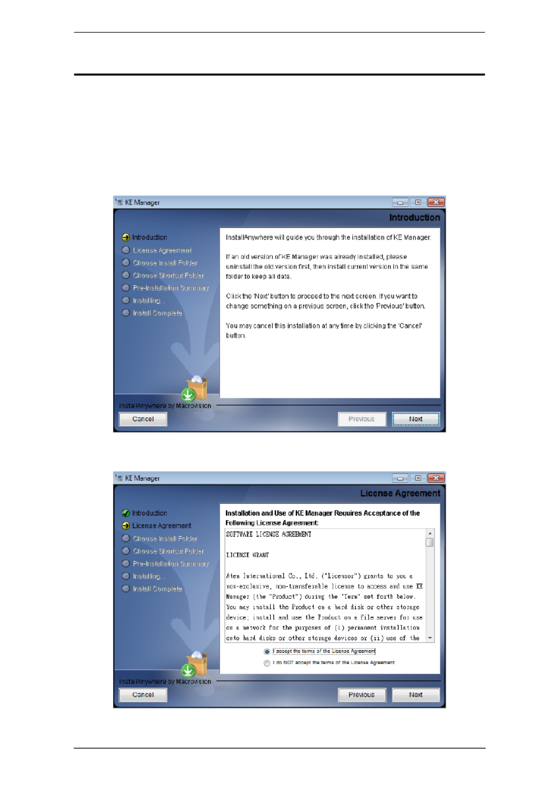
Chapter 4. Software Installation
73
KE Management Software Install
The following are instructions to install the full version of the KE Management
software. For software requirements, see Software, page 5.
1. Insert the USB license key into a USB port on your computer.
2. Double click the KEMangementSetup file to start the setup. When the
Introduction screen appears, click Next.:
3. The License Agreement appears:

KVM Over IP Matrix System User Manual
74
If you agree with the License Agreement, select I accept the terms of
the license agreement, and click Next.
4. The Choose Install Folder screen appears:
Select where you would like to install the program, and click Next.
5. The Choose Shortcut Folder screen appears:
Select where to create shortcuts for the program by selecting the options
provided, and click Next.

Chapter 4. Software Installation
75
6. The Pre-Installation Summary screen appears:
Confirm the settings you’ve selected. If you want to make a change
click Previous to go back, or click Install to begin the software
installation.
7. When the process is done, the Install Complete screen appears:
Click Done.
Note: If you are installing the KE Management software on a second computer
for redundancy (see Redundancy, page 152) – remove the USB License key
and plug it into the primary computer running the KE Management software.

KVM Over IP Matrix System User Manual
76
Upgrading Trial Version
After you purchase a license to upgrade the KE Management Lite version to
the full version of the Matrix Manger software, go to the System tab, and at the
bottom of the Global Settings page, click Upgrade:

77
Chapter 5
Browser / Telnet Operation
Overview
The KE Management Software can be accessed through most standard web
browsers and via Telnet. Once users log in and are authenticated, the browser
GUI comes up. The first section explains the login procedure and web browser
components. The last section provides details for connecting via Telnet.
Logging In
To log into the Matrix Manager, do the following:
1. Open the browser and specify the IP address of the computer installed with
the KE Management software, in the browser's URL location bar.
Note: If the administrator has configured the HTTP or HTTPS port setting
as something other than the default, you must include http:// or
https:// before the IP address, and specify the port number along
with the IP address. For example:
https://192.168.1.20:8443
Where 8443 is the https port number, or 8080 is the http port
number, and a colon is inserted between it and the IP address.
2. If a Security Alert box appears, accept the certificate – it can be trusted
(See Trusted Certificates, page 223 for details). The Login page appears:
3. Enter the Username and Password, and click Login.
Note: Only administrator accounts can be used to login. Username:
administrator | Password: password. For security purposes, we
recommend you change this to something unique.

KVM Over IP Matrix System User Manual
78
The Matrix Manager Main Page
After you have successfully logged in, the web browser’s main page appears:
Web Components
The web components are described in the table, below:
No. Item Description
1 Tab Bar The tab bar contains the Matrix Manager’s main
operation categories: Dashboard, Device
Management, User Management, System, Logs,
and Maintenance.
2 Menu Bar The menu bar contains operational sub-categories
that pertain to the item selected in the tab bar.
3 Sidebar The Sidebar provides a tree view and listing of items
that relate to the various tab bar and menu bar
selections. Clicking an item in the Sidebar brings up
a page with the details that are relevant to it.
4 Logout Click this button to log out of your Matrix Manager
web session.
5 ATEN Logo Click this button to open a new browser window that
opens on the ATEN website.
6 Welcome Message If this function is enabled (see Preferences,
page 168) a welcome message displays here.
7 Interactive Display Panel This is your main work area. The screens that
appear reflect your menu choices and Sidebar item
selection.
1
2
3
4
5
7
6

Chapter 5. Browser / Telnet Operation
79
Tree View Considerations
On some pages there will be a sidebar menu with options that can be expanded:
A plus (+) sign in front of an item means that there are additional items
nested inside of it. Click the plus sign to expand the view and show the
nested items.
The plus sign changes to a minus sign (-)when an item is expanded. Click
the minus sign to collapse the view and hide the nested items.
For devices, if the device is on line, its icon is in green; if it is off line, its
icon is orange.

KVM Over IP Matrix System User Manual
80
The Tab Bar
The functions associated with each of the tabs are explained in the table below:
Icon Function
Dashboard: The Dashboard is used to view information about
current connections, sessions, and device events. The first page
provides an overview and the sidebar provides a link to view details
about each section. The Dashboard is discussed on page 84.
Device Management: The Device Management page is used to
configure and control the overall operation of the devices added to
the Matrix Manager. Device Management is discussed on page 91.
User Management: The User Management page is used to create
and manage Users and Groups. It is also used to assign
permissions to them. User Management is discussed on page 127.
System: The System page is used to configure the KE
Management’s global settings and setup ANMS authorization and
authentication. The System page is discussed on page 142.
Logs: The Log page displays the contents of the log file. The Log
page is discussed on page 156.
Maintenance: The Maintenance page is used to install firmware;
backup and restore configuration information, install certificates, and
set preferences. The Maintenance page is discussed on page 160.

Chapter 5. Browser / Telnet Operation
81
Telnet
The KE Series can be operated and configured via a remote terminal session
using Telnet. This is a useful means for configuring devices when they are first
setup and connected to the network.
To log into the KE Series device by means of a Telnet session, do the
following:
1. On your computer, open a terminal (command line) session.
2. At the prompt, key in the KE device’s IP address in the following way:
telnet [IP address]
3. Press Enter. The login screen appears. At the login prompt, provide the
Password.
Note: The default password for Telnet sessions is password.
Configuration Menu
Once a Telnet connection to the KE device is established, the device’s text-
based Configuration Menu comes up, allowing you to select options by
entering a number on the following screens:
Main Menu
+++++++++++++++++++++++++++++++++++++++++++++++
KE6900 User Station
-- -- -- -- -- -- -- -- --
User Station Configuration
+++++++++++++++++++++++++++++++++++++++++++++++
1. Network
2. Properties
3. System
Q. Logout
Select one:

KVM Over IP Matrix System User Manual
82
1. Network
+++++++++++++++++++++++++++++++++++++++++++++++
KE6900 User Station
-- -- -- -- -- -- -- -- --
Network Settings
+++++++++++++++++++++++++++++++++++++++++++++++
1. IP Installer [Enabled]
2. DHCP [Disabled]
3. IP Address [172.17.17.34]
4. Subnet Mask [255.255.255.0]
5. Default Gateway [172.17.17.254]
Q. Exit
Select one:
2. Properties
+++++++++++++++++++++++++++++++++++++++++++++++
KE6900 User Station
-- -- -- -- -- -- -- -- --
Device Properties
+++++++++++++++++++++++++++++++++++++++++++++++
1. Mode [Matrix]
2. Transmitter Video IP Address [172.17.17.35]
3. Transmitter Audio IP Address [172.17.17.35]
4. Transmitter USB IP Address [172.17.17.35]
5. Transmitter RS232 IP Address [172.17.17.35]
6. UART Configuration
7. Video [Enabled]
8. Audio [Enabled]
9. USB [Enabled]
10. RS232 [Enabled]
11. KE Manager IP [172.17.17.33]
12. KE Manager Port [9110]
13. Beeper [Enabled]
14. USB Mode [VM]
15. USB Secure Transmit [Disabled]
Q. Exit
Select one:

Chapter 5. Browser / Telnet Operation
83
3. System
+++++++++++++++++++++++++++++++++++++++++++++++
KE6900 User Station
-- -- -- -- -- -- -- -- --
System Setting
+++++++++++++++++++++++++++++++++++++++++++++++
1. Device Name [KE6900R]
2. Device Description [Receiver1]
Device IP Address: 172.17.17.34
Device MAC Address: 00:10:74:A8:01:23
Device FW Version: V1.1.109
Device Serial Number:
3. Password [Enabled]
4. Change Password
5. System Reboot/Reset to Factory Default
Q. Exit
Select one:

84
Chapter 6
Dashboard
Overview
The Dashboard tab is used to view events about connections, sessions, online
devices and schedules. The Home page provides an overview of the
information provided in each section. The Sidebar provides a link to each
section in the Dashboard.
The Dashboard opens on the Home page, as shown here:
At the bottom of the page, click Shutdown* to stop the KE Manager service,
or Restart to stop and restart the service. Both options will logout all user web
sessions.
Note: Clicking Shutdown stops the KE Manager service and web sessions
will not be available until the KE Manager service is restarted.

Chapter 6. Dashboard
85
Active Connections
The Active Connections page lets an administrator see the active Channel
connections (User Stations connected to Transmitters) and provides
information about each of their sessions.
The meanings of the headings at the top of the page are straightforward.
Channel refers to the defined Transmitter connection in use by the User
Station.
Streams refers to the type of source the connection is streaming: Video,
A U Sudio, SB, or erial.
Access Mode refers to the type of access (Exclusive, Occupy, Share, View
only) that the User Station is connecting with.
User Station refers to the Receiver that is being used to access the Channel
connection.
Username refers to the user that logged into the User Station to establish
the connection.
Start Time refers to the date/time the connection between the User Station
and Transmitter began.
Operation provides a Disconnect button that allows you to disconnect the
active connection.
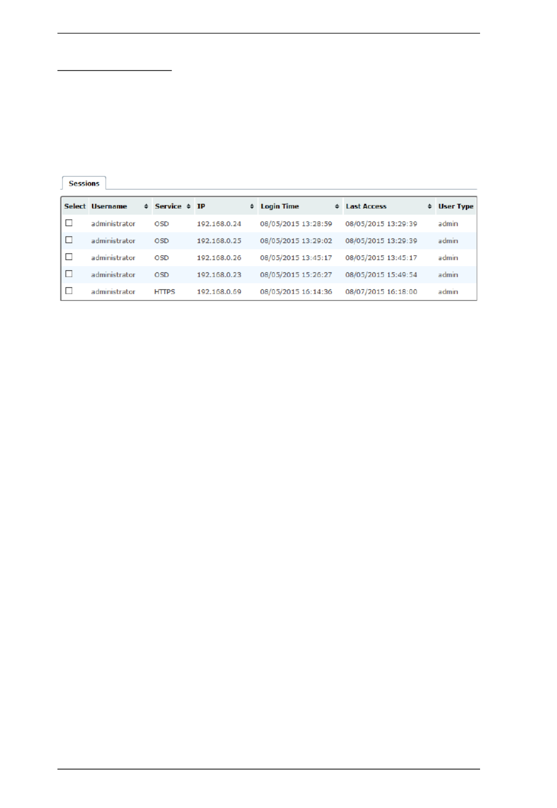
KVM Over IP Matrix System User Manual
86
Active Sessions
The Active Sessions page shows all of the users that are logged into KE
Management and OSD sessions and provides information concerning the
“who, where and when” of each session. This page also gives the administrator
the option of forcing a user logout by selecting the user and clicking Kill
Session from the bottom of the page.
The meanings of the headings at the top of the page are straightforward.
Select allows you to check boxes and use the Kill Session button at the
bottom of the page to force users to logout.
Username refers to the user that logged into the User Station to establish
the connection.
Service refers to how the user logged into their session – via Matrix
Manger or OSD.
IP refers to the IP address of the device from which the user has logged in.
Login Time refers to the date/time that the user logged into the KE
Management software or OSD session.
Last Access refers to the last time the user session was active and in use.
User Type refers to the account type that the user is logged in with.

Chapter 6. Dashboard
87
Online User Stations
The Online User Stations page lets the administrator see all of the Receivers
that are currently available on the network and provides information about each
device.
The meanings of the headings at the top of the page are straightforward.
ID refers to the identification number assigned by the system.
Name refers to the name entered on the User Stations System page.
Model Name refers to the Receiver model number.
Status refers to the User Station’s online status.
Address refers to the IP address of the User Station.
Streams refers to the source type that the User Station is configured to
stream: Video, Audio, USB, and Serial.

KVM Over IP Matrix System User Manual
88
Online Transmitters
The Online Transmitters page lets the administrator see all of the Transmitters
that are currently available on the network and provides information about each
device.
The meanings of the headings at the top of the page are straightforward.
ID refers to the identification number assigned by the system.
Name refers to the name entered on the Transmitter’s System page.
Model Name refers to the Transmitter model number.
Status refers to the Transmitter’s online status.
Address refers to the IP address of the Transmitter.
Streams refers to the source type that the Transmitter is configured to
stream: Video, Audio, USB, or Serial.

Chapter 6. Dashboard
89
Latest Events
The Latest Events page lets the administrator see the most recent Dashboard
events that relate to the current connections and sessions, and provides details
about each.
The meanings of the headings at the top of the page are straightforward.
Time refers to the date and time that the event occurred.
User refers to the username that the event relates to. If no username
appears, the event is general system information.
Severity refers to the event’s severity type: Information, Error, or Warning
Device refers to the Transmitter or User Station that relates to the event. If
no device is listed the event refers to the KE Management software.
Log Information provides detailed information about each event.

KVM Over IP Matrix System User Manual
90
Schedule
The Schedule page lets the administrator see all of the Profiles and Video Walls
that are scheduled to activate.
The meanings of the headings at the top of the page are straightforward.
Profiles/Video Walls refers to the ID number created for the Profile or
Video Wall schedule.
Routine Type refers to how often the Profile or Video Wall is scheduled to
repeat.
Day refers to either the day of a week (Monday to Sunday) or a day of the
month that the Profile or Video Wall is scheduled to run.
Start Date refers to the date that the Profiles or Video Wall is scheduled to
start.
End Date refers to the date that the Profile or Video Wall is scheduled to
end.
Connect Time refers to the time of day that the Profile or Video Wall is
scheduled to make its connection(s).
Disconnect Time refers to the time of day that the Profile or Video Wall is
scheduled to disconnect its connection(s).
Apply refers to the date and time when the Profile or Video Wall schedule
was created.
Operation provides a Delete button that can be used to permanently delete
the Profile or Video Wall schedule.

91
Chapter 7
Device Management
Overview
The Device Management tab contains five menu bar items: User Stations,
Transmitters, Channels, Profiles and Video Wall. Each page provides a way
to add, configure and schedule the Transmitters/Receivers connections. Before
Transmitters and Receivers can be added they must be connected to the
network and have an IP address.
The Device Management tab opens on the User Stations page, as shown here:

KVM Over IP Matrix System User Manual
92
User Stations
The User Stations page allows you to add and configure Receivers. The
Sidebar provides three menu options: User Stations, Unmanaged User
Stations and User Station Video Group. User Stations are the Receivers that
have been added to the KE Management software. Unmanaged User Stations
are Receivers that have been found on the network but haven’t been added to
the KE Management software. To discover a Receiver, it must be connected to
the network and have an IP address. User Station Video Group lists
Transmitters that have been grouped to share the video from one computer.
Click User Stations from the menu bar and the following screen appears:
The main page provides an overview of each User Station. The Sidebar
provides a link with a more detailed view of each.
The meanings of the headings at the top of the page are straightforward.
ID refers to the identification number assigned by the system.
Name refers to the name entered on the User Stations’s System page.
Model Name refers to the Receiver model number.
Access Mode refers to the User Station’s mode set in the Properties.
Status refers to the User Station’s online status.
Address refers to the IP address of the User Station.
Streams refers to the source type that the User Station is configured to
stream: Video, Audio, USB, and Serial.
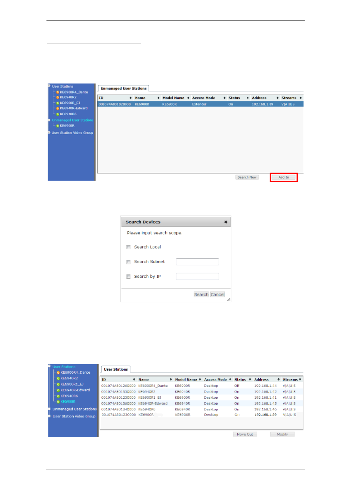
Chapter 7. Device Management
93
Adding a User Station
To add a User Station, do the following:
1. From Unmanaged User Stations, select a User Station and click Add in:
or click Search New:
You can search for a device by , or Local, Subnet IP address. Select a
scope, enter the information and click Search.
2. Once added, the User Station appears on the User Stations main page and
in Sidebar menu:

Chapter 7. Device Management
95
3. Click the tab to configure theProperties User Station’s properties:
Network
Configuration
For dynamic IP address assignment, select the Obtain IP
address automatically radio button.
To specify a fixed IP Address, Subnet Mask, and Default
Gateway select the radio button and Set IP address manually
fill in the fields with values appropriate for your network.
For information to configure the network settings locally on the
device see Network Configuration, page 44.
Item Description
Mode Select Extender mode for simple one-to-one (Transmitter to
User Station) setups that are managed mostly with the
Receiver’s OSD menu.
Select Matrix mode to manage devices and connections from
the KE Management software. This mode is for advanced setup
and administration of Transmitter to User Station connections
via the Matrix Manger browser UI. (See Channel Connections,
page 110)
Properties If you selected Extender mode (above) set the Transmitter IP
address for the User Station’s Video, Audio, USB, and RS232
source signals.
If you selected Matrix mode (above) the will be Properties
grayed out. Use Channels to configure the Transmitter
connections. (See Channel Connections, page 110)
Item Description

Chapter 7. Device Management
97
(Continues on next page.)
USB Mode Select the type of USB device you will connect to the USB ports:
Virtual Media: Select this option only if you are plugging a USB
disk drive (including USB HDD/optical disk) into the USB ports.
This will give you the highest data transfer speeds but will not
allow other USB devices to work when plugged into the USB
ports. When user stations connected to the same transmitter
mount or unmount USB disk drives, the keyboard and mouse
operations will experience a brief delay. Transmitters can
support up to 12 virtual media connections at the same time
(keyboard/mouse included).
Generic USB device: Use this option to plug USB peripherals
into the USB ports. This option also allows a keyboard and
mouse with special functions to plug into the USB ports for
console use. Use this only if the special functions of the
keyboard or mouse are required but do not work when plugged
into the console ports. When the keyboard and mouse are
plugged into the USB ports, they will not work within the OSD
menus. To work within the OSD menus, the keyboard and
mouse must be plugged into the console ports. KE6900ST
transmitters do not support the Generic USB Device mode. In
this mode, KE6900/KE6940 transmitters supports up to 2 USB
connections; and KE8950/KE8952 transmitters support up to 5
USB connections (keyboard/mouse excluded).
Encryption: Check this box to encrypt USB disk drives plugged
into the USB ports.
Item Description

KVM Over IP Matrix System User Manual
98
4. Click the System tab to configure the general settings:
5. After entering the information, click Save.
Item Description
General Enter the Name, Location, and Description of the User
Station. This section also displays the User Station’s IP
Address, F/W Version, Model Name, MAC Address and MFG*.
Note: The MFG number (manufacturing number) is an internal
serial number for our factory and technical support staff to
identify products. This number does not affect any product’s
warranty. If your product needs after-sales services, you may
provide the MFG Number to our sales or technical support staff
to identify the product and model number.
Reboot Check the box and click Reboot to reset the User Station’s
settings back to the factory default. All custom settings will be
lost.
User Station
Password
Change
Check Enable to require a password to access the User
Station’s OSD configuration screens (see page 49).
Enter the Old Password, enter a New Password, and confirm
the new password in the Confirm Password box.

KVM Over IP Matrix System User Manual
100
User Station Video Group
Creating a User Station Video Group allows you to cascade up to four
Transmitters connected to separate video cards on a computer and share the
video with four or eight (dual display) User Stations with the first having
keyboard and mouse access. The image below provides an example of the
setup without the actual physical connections or possible device connections.
Note: User Station Video Groups cannot be used with a Video Wall or Profile.
Hardware Setup
1. Connect each Transmitter to the network and to a DVI port on the com-
puter.
2. Connect one Transmitter’s – console & KVM ports to their respective
device (keyboard/mouse/computer).
Transmitters
Receivers
A
A
A
A
PC
Max 8 monitors
with dual display.

Chapter 7. Device Management
101
3. Setup the Receivers as you normally would. All Receivers can have a
keyboard and mouse but only one (Video 1) can work on the computer for
the group.
4. Note the Receiver and Transmitter with keyboard and mouse access (to the
computer) so they can be set in the User Station Video Group (as Video 1)
and in the Channel (as KVM Transmitter).
Adding a User Station Video Group
1. Add the User Stations (Adding a User Station, page 93) and Transmitters
(Adding a Transmitter, page 104) to the KE Management software.
2. On the left Sidebar select User Station Video Group.
3. Provide a Name and Description for the group.
4. Use the Video 1 drop-down menu to select the Receiver that will have
keyboard and mouse access to the computer.

KVM Over IP Matrix System User Manual
102
Note: All Receivers can switch KVM access to other Transmitters but only
Video 1 has keyboard and mouse access to the computer for the group.
5. Use the Video 2, Video 3 and Video 4 drop-down menus to select the
other Receivers for the group.
6. Click Save. The group appears in the Sidebar.
7. On the menu bar, go to Channels.
8. Add a new Channel.
9. Set the Source Stream to map the Transmitters to the User Station Video
Group Receivers, as such: KVM Transmitter
→ Video 1; Video 2 → Video
2; Video 3 → Video 3; Video 4 → Video 4.
Use the KVM Transmitter drop-down menu to select the Transmitter
connected to the computer’s keyboard and mouse ports.
Use the Video 2, Video 3 Video 4 and drop-down menus to select the
other Transmitters connected to the computer.
Use the Audio, USB and Serial drop-down menus to select the
Transmitter for each source signal. The Transmitter selected sends the
signal to the Receiver set with the same Video #.
10. Configure the remaining Channel settings (see Adding a Channel,
page 112).
11. Click Save.

Chapter 7. Device Management
103
Transmitters
The Transmitters page allows you to add, configure, and delete Transmitters.
The Sidebar provides two options: Transmitters and Unmanaged
Transmitters. Unmanaged Transmitters are Transmitters on the network that
haven’t been added to the KE Management software. For the KE Management
software to discover a Transmitter, it must be connected to the local network
with an IP address.
Click Transmitters from the menu bar and the following screen appears:
The main page provides an overview of each Transmitter. The Sidebar
provides a link with a more detailed view of each.
The meanings of the headings at the top of the page are straightforward.
ID refers to the identification number assigned by the system.
Name refers to the name entered on the Transmitter’s System page.
Model Name refers to the Transmitter’s model number.
Access Mode refers to the Transmitter’s mode set in the Properties.
Status refers to the Transmitter’s online status.
Address refers to the IP address of the Transmitter.
Streams refers to the source type that the Transmitter is configured to
stream: Video, Audio, USB, or Serial.
Produktspecifikationer
| Varumärke: | ATen |
| Kategori: | Växla |
| Modell: | KE8950-AX-E |
| Färg på produkten: | Zwart |
| Vikt: | 3170 g |
| Bredd: | 240 mm |
| Djup: | 398.5 mm |
| Höjd: | 207.4 mm |
| Förpackningens vikt: | 3900 g |
| Förpackningens bredd: | 300 mm |
| Djuppackning: | 450 mm |
| Förpackningshöjd: | 255 mm |
| Snäll: | PC |
| Vormfaktor: | kubus |
| Antal USB 2.0-portar: | 1 |
| Ljudingångar: | Ja |
| Ljudutgång: | Ja |
| Material: | Polymer, Steel |
| Antal portar USB 3.2 Gen 1 (3.1 Gen 1) Typ A: | 2 |
| Strömförsörjning ingår: | Nee |
| Antal 5,25" fack: | 1 |
| Antal 3,5" fack: | 3 |
| Maximalt antal hårddiskar per hölje: | 3 |
| Hårddiskstorlekar som stöds: | 3.5 " |
| Antal expansionsplatser: | 2 |
| Lagen per pallet: | 8 stuk(s) |
| Moderkortsformfaktorer som stöds: | Mini-ITX |
| Maximal CPU-kylarhöjd: | 65 mm |
| Maximal grafikkortslängd: | 343 mm |
| Maximal PSU-längd: | 180 mm |
| Maximalt antal främre fläktar: | 1 |
| Främre fläktar som stödjer diametrar: | 120 mm |
| Formfaktorer för strömförsörjning som stöds: | ATX |
| Antal främre fläktar installerade: | 1x 120 mm |
| Maximalt antal sidofläktar: | 1 |
| Sidofläktar som stödjer diametrar: | 80 mm |
| Antal interna 3,5" fack: | 3 |
| Hårddisk/SSD-kombimodell: | Ja |
| Installerade sidofläktar: | 1x 80 mm |
Behöver du hjälp?
Om du behöver hjälp med ATen KE8950-AX-E ställ en fråga nedan och andra användare kommer att svara dig
Växla ATen Manualer

29 December 2024
10 September 2024
10 September 2024
10 September 2024
10 September 2024
10 September 2024
10 September 2024
9 September 2024
9 September 2024
9 September 2024
Växla Manualer
- Växla Bosch
- Växla IKEA
- Växla Huawei
- Växla HP
- Växla Philips
- Växla Panasonic
- Växla Honeywell
- Växla Yamaha
- Växla Abus
- Växla Alcatel
- Växla Alecto
- Växla Apc
- Växla Alpine
- Växla Ansmann
- Växla Airlive
- Växla Edimax
- Växla Intermatic
- Växla Flamingo
- Växla Brennenstuhl
- Växla Hikvision
- Växla Generac
- Växla Silvercrest
- Växla Nedis
- Växla Pyle
- Växla Asus
- Växla Eminent
- Växla Renkforce
- Växla Vivanco
- Växla TP Link
- Växla Manhattan
- Växla Worx
- Växla Black Box
- Växla Elro
- Växla EMOS
- Växla Victron Energy
- Växla KlikaanKlikuit
- Växla Ei Electronics
- Växla Tripp Lite
- Växla DataVideo
- Växla Schneider
- Växla Hama
- Växla Theben
- Växla Elektrobock
- Växla Chamberlain
- Växla Sylvania
- Växla Velleman
- Växla Tork
- Växla Techly
- Växla Sonance
- Växla Emerson
- Växla Totolink
- Växla Vemer
- Växla Smartwares
- Växla Profile
- Växla Cisco
- Växla Matrox
- Växla Steren
- Växla Perel
- Växla Engenius
- Växla IFM
- Växla Digitus
- Växla Kathrein
- Växla AV:link
- Växla Belkin
- Växla Linksys
- Växla Buffalo
- Växla Dahua Technology
- Växla Audiovox
- Växla Cotech
- Växla Netgear
- Växla LevelOne
- Växla Kaiser
- Växla QNAP
- Växla Trotec
- Växla Boss
- Växla Behringer
- Växla PreSonus
- Växla Shimano
- Växla Merten
- Växla Goobay
- Växla Hager
- Växla Mercusys
- Växla Chacon
- Växla Elation
- Växla Sygonix
- Växla Planet
- Växla ZyXEL
- Växla Rex
- Växla Clas Ohlson
- Växla Powerfix
- Växla Konig
- Växla Tesla
- Växla D-Link
- Växla Tenda
- Växla UPM
- Växla One For All
- Växla Finder
- Växla Fantini Cosmi
- Växla Audac
- Växla Marmitek
- Växla Delta Dore
- Växla DoorBird
- Växla Ubiquiti Networks
- Växla EBERLE
- Växla Grasslin
- Växla Omnitronic
- Växla Eaton
- Växla Gira
- Växla Jung
- Växla Vacmaster
- Växla CyberPower
- Växla Basetech
- Växla Trendnet
- Växla Mikrotik
- Växla WHALE
- Växla Fibaro
- Växla RGBlink
- Växla Gefen
- Växla Nexa
- Växla PAC
- Växla Wentronic
- Växla Dormakaba
- Växla Adder
- Växla Wago
- Växla Homematic IP
- Växla Monoprice
- Växla Tiptel
- Växla OSD Audio
- Växla SPC
- Växla Crestron
- Växla Unify
- Växla ORNO
- Växla Toolcraft
- Växla Berker
- Växla Aeon Labs
- Växla Electro Harmonix
- Växla Grandstream
- Växla Mercury
- Växla Provision ISR
- Växla Monacor
- Växla PCE
- Växla Logilink
- Växla Smart-AVI
- Växla StarTech.com
- Växla SIIG
- Växla Advantech
- Växla IOGEAR
- Växla Merlin Gerin
- Växla Micro Connect
- Växla Extron
- Växla KanexPro
- Växla Intelix
- Växla Blustream
- Växla Avocent
- Växla Shelly
- Växla Intellinet
- Växla Ebode
- Växla Lancom
- Växla Robbe
- Växla ICasa
- Växla B-tech
- Växla Speaka
- Växla Kopp
- Växla Vimar
- Växla Kemo
- Växla GAO
- Växla H-Tronic
- Växla Legrand
- Växla Kraus & Naimer
- Växla Noble
- Växla Intertechno
- Växla Ecler
- Växla Inverto
- Växla Triax
- Växla Rule
- Växla Kramer
- Växla CYP
- Växla Suevia
- Växla Phoenix Contact
- Växla Seuthe
- Växla Maclean Energy
- Växla SmartAVI
- Växla Leviton
- Växla DEHN
- Växla Cudy
- Växla Brilliant
- Växla Heitronic
- Växla Lindy
- Växla SEC24
- Växla Cooking Performance Group
- Växla Ernitec
- Växla Atlona
- Växla Adviti
- Växla Flic
- Växla HELGI
- Växla IB Connect
- Växla Liberty
- Växla PureTools
- Växla Hamlet
- Växla Paladin
- Växla Equip
- Växla Noark
- Växla Vivolink
- Växla Alfatron
- Växla Cambium Networks
- Växla 2USB
- Växla Roline
- Växla KVM-TEC
- Växla AMX
- Växla BZBGear
- Växla STI
- Växla Epiphan
- Växla Ebara
- Växla Mach Power
- Växla Axing
- Växla Juniper
- Växla Raritan
- Växla ConnectPro
- Växla SunBriteTV
- Växla Atlantis Land
- Växla GEV
- Växla Pizzato Elettrica
- Växla Baco
- Växla SEADA
- Växla Doepke
- Växla Comet
- Växla IPGARD
- Växla CSL
- Växla Setti+
- Växla PureLink
- Växla INOGENI
- Växla Luxul
Nyaste Växla Manualer
9 April 2025
9 April 2025
7 April 2025
5 April 2025
5 April 2025
5 April 2025
5 April 2025
3 April 2025
3 April 2025
2 April 2025