Gefen EXT-UHDKA-LANS-RX Bruksanvisning
Läs nedan 📖 manual på svenska för Gefen EXT-UHDKA-LANS-RX (179 sidor) i kategorin Växla. Denna guide var användbar för 5 personer och betygsatt med 4.5 stjärnor i genomsnitt av 2 användare
Sida 1/179
EXT-UHDKA-LANS-TX / EXT-UHDKA-LANS-RX
EXT-DPKA-LANS-TX / EXT-DPKA-LANS-RX
EXT-DVIKA-LANS-TX / EXT-DVIKA-LANS-RX
EXT-VGAKA-LANS-TX / EXT-VGAKA-LANS-RX
User Manual
Version A2
Gen 2.0 KVM over IP

2
Important Safety Instructions
1. Read these instructions.
2. Keep these instructions.
3. Heed all warnings.
4. Follow all instructions.
5. Do not use this product near water.
6. Clean only with a dry cloth.
7. Do not block any ventilation openings. Install in accordance with the manufacturer’s
instructions.
8. Do not install or place this product near any heat sources such as radiators, heat registers,
9. Do not defeat the safety purpose of the polarized or grounding-type plug. A polarized
plug has two blades with one wider than the other. A grounding type plug has two blades
and a third grounding prong. The wide blade or the third prong are provided for your
-
ment of the obsolete outlet.
10. Protect the power cord from being walked on or pinched particularly at plugs,
convenience receptacles, and the point where they exit from the apparatus.
11.
12. To reduce the risk of electric shock and/or damage to this product, never handle or touch
this unit or power cord if your hands are wet or damp. Do not expose this
product to rain or moisture.
13. Unplug this apparatus during lightning storms or when unused for long periods of time.
14.
apparatus has been damaged in any way, such as power-supply cord or plug is
damaged, liquid has been spilled or objects have fallen into the apparatus,
the apparatus has been exposed to rain or moisture, does not operate normally,
or has been dropped.
15. Batteries that may be included with this product and/or accessories should never be
according to the instructions.

3
Warranty Information
For the latest warranty coverage information, refer to the Warranty and Return Policy under
the Connect section of the Gefen website at http://www.gefen.com/connect/warranty-and-
return-policy

4
Contact Us
Technical Support
1-707-283-5900 1-800-472-5555
8:00 AM to 5:00 PM Monday - Friday, Pacic Time
Email
support@gefen.com
Web
http://www.gefen.com
Mailing Address
Gefen
Nortek Security & Control, LLC
c/o Customer Service
1800 S McDowell Blvd
Petaluma, CA 94954 USA
© 2018 Noretk Security & Control, LLC. All Rights Reserved.
All trademarks are the property of their respective owners.
Gefen and Nortek Security & Control, LLC reserve the right to make changes in the hardware,
packaging, and any accompanying documentation without prior notice.

5
Operating Notes
•
•
•
controlling the operation of an AV-over-IP network using these products. Alternatively,
•
•
•
• By default, each device is setup in unicast mode and the source device will use the EDID
• If
Network Cable Diagram (page 175 for details.
This product uses UL-Listed power supplies
Important
•
enabled.
•
• Only the HDMI and DisplayPort Inputs and Outputs will pass content from
systems. Other formats do not support HDCP content. If HDCP encrypted
content is being passed, the output will not be active.
•
Area Network.
• Always make sure that all units within a system are running the latest

6
Operating Notes
Supported USB Devices
► HID-class devices: keyboard, mouse, joystick, and touch panels.
►
readers, and printers.
• Known supported devices
►
►
► Connectivity devices: infrared remote controller, Bluetooth dongle.
►
►
•
► High-speed isochronous devices, such as webcams are NOT supported.
Licensing
For three years from date of activation of this product, any party may request, and we will supply,
their respective open source licenses:
• jQuery
•

7
Features
•
Network
•
•
• HDMI and DisplayPort products support input resolutions up to 4K 60Hz 4:2:0 and
output resolutions up to 4K 30Hz 4:4:4
• DVI and VGA products support input and output resolutions up to 1080p Full HD and
•
• KM Emulation feature facilitates real-time, simultaneous Keyboard and Mouse control of
each source from all connected workstations
• Integrated scaler ensures maximum compatibility and best possible viewing experience
• Built-in video wall controller accommodates any number of rows and columns up to
16x16
• Built-in Audio De-Embedder on HDMI and DisplayPort Receivers breaks out 2 channel
analog, 2 channel PCM, and up to 5.1 channels of Bitstream audio from the HDMI signal,
systems for added impact
•
Controller
• Enhanced API for added functionality with third-party control systems
• Built-in web interface, Telnet, and UDP
•
download at www.gefen.com
•
depending on the network bandwidth and number of ports on your network switch
•
1.1
•
•
be powered through a standard PoE-enabled IP network switch, without the need for
external power supplies
• Two-port Gigabit Ethernet switch built into the Receiver unit
• All trademarks and registered trademarks are properties of their respective owners.
Features & Packing List

8
Features & Packing List
Packing List - Sender Unit
The following items are included in the Sender Unit package. If any of these items are not
present in the box when you rst open it, please contact Gefen Technical Support as soon as
possible.
(1) Sender unit
(1) 5V 2.6A Power Supply
(4) Self-Adhesive Rubber-Feet
(2) L-Shaped Mounting Brackets
(4) Machine screws for L-Shaped Mounting Brackets
(2) Machine screws for EXT-RACK-1U-GRY (sold separately)
(1) Quick-Start Guide
Packing List - Receiver Unit
The following items are included in the Receiver Unit If any of these items are not present in .
the box when you rst open it, please contact Gefen Technical Support as soon as possible.
(1) Receiver unit
(1) 5V 4A Power Supply
(1) AC Power Cord
(4) Self-Adhesive Rubber-Feet
(2) L-Shaped Mounting Brackets
(4) Machine screws for L-Shaped Mounting Brackets
(2) Machine screws for EXT-RACK-1U-GRY (sold separately)
(1) Quick-Start Guide
• Mode switch on Sender for sharpness or motion-optimization of image
• Field-updatable rmware via EXT-CU-LAN controller or the built-in web server interface
• Locking power supply connectors
• Half-rack width Sender and Receiver enclosures are rack-mountable using EXT-RACK-1U-
GRY
• Sender and Receiver can also be surface-mounted using the included L-brackets
• Low prole Receiver enclosure features an IR Extender port and can be hidden away
behind the display
* Features and specications are subject to change without notice.
** Pending features to be activated via an upcoming rmware update.
All trademarks and registered trademarks are properties of their respective owners.

12
ID Name Description
6 5V DC This power receptacle is used to connect the
included 5V DC power supply. An external
power supply is not required when connecting
to a PoE-enabled switch using the LAN (PoE)
port.
7USB Connect a USB cable from the computer to this
USB port.
8LAN (PoE) Connect a CAT-5e or better cable up to 330
feet/100 meters, from this port to a PoE-
capable network switch. If a PoE switch is
not available, then the included 5V DC power
supply must be connected to the Sender unit.
9RS-232 Connect an DB-9 cable from this port to a
RS-232 automation control unit. See RS-232
Control (page 43) for more information.
10 Prog Sel For normal operation, this switch should be in
the position. Setting this switch to the On
position, places the unit in the ready-state for
rmware recovery or debug operations.
11 Video Out (except
DisplayPort™)
Use a high quality video interconnect cable
to the connect an AV source to the video Out
port on the rear panel of the Sender unit.
When using HDMI Senders, we recommend
Gefen cables.
12 Video In a high quality video interconnect cable Use
to the connect an AV source to the video
In port on the rear panel of the Sender
unit. When using HDMI and DisplayPort™
Senders, we recommend Gefen cables.
Introduction

13
ID Name Description
13 IR In/Ext Connect an IR Extender (Gefen part no.
EXT-RMT-EXTIRN) to this port. Alternatively,
connect a 3.5mm mini-stereo connector
from this port to the output of an
automation system with an electrical IR
output.
14 IR Out Connect an IR Emitter (Gefen part no. EXT-
IREMIT) from this port to the IR sensor of the
device to be controlled.
15 Line In Connect a 3.5mm mini-stereo cable from this
port to the analog audio source.
16 Line Out Connect a 3.5mm mini-stereo cable from this
port to an amplier or other audio output
device.
Introduction

16
Introduction
ID Name Description
13 RS-232 Connect a DB-9 cable from the Receiver
unit to the display or another device to be
controlled. See RS-232 Control (page 43)
for more information.
14 Prog Sel For normal operation, this switch should be in
the position. Setting this switch to the On
position, places the unit in the ready-state for
rmware recovery or debug operations.
15 Opt Out (except VGA) Connect a digital audio cable with a TOSLINK®
connectors from this port to the digital audio
input of an AV receiver or amplier.
16 USB 1.1 Connect up to two USB 1.1 or HID devices (such
as keyboard, mouse, or touchscreen) to these
USB ports. For USB 2.0 devices, use the USB
2.0 ports. Please note that the KM Emulation
feature only works with these two USB 1.1 ports. It
is not available with the USB2.0 ports.
17 LAN 1 Use this port to connect IP-enabled devices,
or to daisy-chain additional Receiver units
(only when a single source is used, otherwise
bandwidth may be compromised). CAT-5e or
better cables up to 330 feet/100 meters. This
port is NOT PoE -capable.
18 LAN 2 (PoE) Connect a CAT-5e or better cable up to 330
feet/100 meters, from this port to a PoE-
capable network switch. If a PoE switch is
not available, then the included 5V DC power
supply must be connected to the Receiver unit.
19 5V DC This power receptacle can be used to connect
the included 5V DC power supply. An external
power supply is not required when connecting
to a PoE-enabled switch using the LAN 2 (PoE)
port.

17
The Gen 2.0 KVM over IP Sender and Receiver units can be connected directly or through a
Local Area Network (LAN). Both installations will be covered.
Local Area Network (LAN) Connection
When connecting the Sender and Receiver units to a Local Area Network (LAN), DHCP, static,
or APIPA (Automatic Private IP Addressing) IP modes can be used. DHCP mode will use the
DHCP server to automatically assign an IP address for each Sender and Receiver unit that
is connected to the network. Static IP mode will allow the IP address for each Sender and
Receiver unit to be congured manually. Contact your network administrator if necessary.
APIAP mode assigns a class-B IP address, in the 169.254.x.x range, to the Sender and
Receiver units, if a DHCP server is not available.
1. Connect a CAT-5e (or better) cable between the LAN (PoE) port on the Sender unit and a
Gigabit PoE-enabled IP switch.
2. Connect LAN 2 (PoE) on the Receiver unit to the same network switch. Each cable run can
be up to 330 feet (100 meters).
3. If NOT USING A PoE-compliant switch, then connect the included 5V DC power supplies
to the Sender and Receiver units.
Installation
Important
If the IP switch is PoE-compliant and the Sender and Receiver are connected
through their PoE ports, external power supplies will not be required. However,
additional Receivers or other devices connected to the LAN 1 port of a Receiver will
require an external power supply.
to PoE-compatible switch
Sender unit
Off On
EXT-UHDKA-LANS-TX
Line OutIR OutIR In/ExtHDMI InHDMI OutProg SelRS-232LAN (PoE)USB5V DC Line In

21
16. Click the desired button.IP Mode
• If Static
Contact your system administrator if necessary.
• If mode is selected, then the IP address, subnet mask, and default gateway will be DHCP
17. Click the button to save the changes. This operation will require a reboot.Apply
18. Click the Reboot button near the bottom of the page.
19.
20.
27 for more information.
Installation
Important
capability is required when connecting the Gefen AV over IP products to a network.

22
Installation
Using a Direct Connection
By default, all Senders and Receivers are shipped in APIPA (Auto) mode. This network
mode is used for directly connecting Sender and Receiver units to one another. In APIPA
mode, each Sender and Receiver unit assigns itself a unique IP address within the range of
169.254.x.x. Using a direct connection each unit can remain in Auto mode of can be
assigned a static of DHCP IP address using the Gefen Syner-G sofrware or manually through
the built-in web interface.
1. Connect an HDMI cable to connect the source to the HDMI In port on the Sender unit.
2. Connect an HDMI cable from the display to the port on the Receiver unit.HDMI Out
3. Connect a CAT-5e (or better) cable from the LAN (PoE) port on the Sender unit to the
LAN 1 or LAN 2 (PoE) port on the Receiver unit. The other LAN port can then be used for
connecting (daisy-chaining) an additional Receiver unit. Each cable run can be up to 330
feet (100 meters). Please note that PoE is not active in direct connection. The Sender and
all connected Receivers will need to be powered using their external power supplies.
4. Connect the included 5V DC locking power supplies to both the Sender unit and Receiver
unit. Do not overtighten the locking connectors. Plug the power supplies to available
electrical outlets.
5. Obtain the IP address of both the Sender and Receiver unit by disconnecting the video
cable from the Sender unit (or from the source device). Information, similar to the illus-
tration on the next page, will be displayed.
Off On
EXT-UHDKA-LANS-TX
Line OutIR OutIR In/ExtHDMI InHDMI OutProg SelRS-232LAN (PoE)USB5V DC Line In
EXT-UHDKA-LANS-RX
Off On
IR In/Ext IR Out HDMI Out Prog Sel Opt Out USB 1.1 LAN 1 LAN 2 (PoE) 5V DCRS-232
Receiver unit to IP-enabled devices
Sender unit

23
6. Make note of both IP addresses. These IP addresses can be entered in a Web browser to
access the built-in Web interface.
7. See Local Area Network (LAN) Connection (page )17 and follow steps 4 - 20,
in order to access the built-in Web interface.
8. Set the video channel. By default, both the Sender and Receiver unit are set
to channel 0. See Setting the Video Channel (page )27 for more information.
9. Once both Sender and Receiver units are congured using the built-in Web
interface, the shielded CAT-5e cable, between the PC and the Receiver unit,
can be disconnected.
10. See Supplementary Connections (page )24 for instructions on connecting USB,
IR, RS-232, and audio cables.
Installation
Waiting for video source - standby
FW: V1.53H-Oct-24 779c
Local IP: 169.254.7.231
Remote IP: 169.254.6.250
ID: 001C9103C003
Remote IP = Sender unit
Local IP = Receiver unit

24
Installation
Supplementary Connections
► USB
See USB Control (page )46 for more information on using USB devices.
1. Connect a USB cable from the computer to the port on the Sender unit.USB
2. Connect a maximum of two USB 2.0 devices to the USB 2.0 ports, on the front panel of
the Receiver unit. For USB 1.1 devices, connect the devices to the USB 1.1 ports.
► IR
3. Connect an IR Emitter (Gefen part no. EXT-IREMIT) to the Sender unit and attach
it to the IR sensor on the device to be controlled.
4. Connect an IR Extender (Gefen part no. EXT-RMT-EXTIRN) to the Receiver unit if the IR
sensor will not be within line-of-site for proper IR control.
► Audio
See Audio Connections (page 53) for more information on using audio devices.
5. Connect a 3.5mm mini-stereo cable from the Line In port on the Sender unit to an audio
source.
6. Connect a pair of powered speakers (or another audio output device) to the Line Out port
on the Receiver unit.
7. Connect a USB microphone / headset to one of the USB 2.0 ports on the Receiver unit
8. Connect a pair of powered speakers (or another audio output device) to the Line Out port
on the Sender unit.
► RS-232
9. Connect an RS-232 cable from the PC or automation system to the RS-232 port on the
Sender unit.
10. Connect an RS-232 cable from the Receiver unit to the RS-232 device to be
controlled.

26
LED Status
The Power and Link
on their current status.
Link
Description
• Connection is not established.
•
unit.
On • Connection is established and video is streaming.
Blinking
•
established but streaming has not started.
• No video source detected.
• Check that the Receiver unit is connected to the
host.
Power
Description
• No power.
On • Power is on and the system is ready.
Blinking
•

28
Setting the Video Channel
Setting the Channel using the Front Panel
1. Press the - or button to display the current channel number. Channel numbers +/USB
range from 0 to 39900.
2. The current video channel of the Receiver unit will be shown on the connected display.
3. While the current video channel is being displayed, press and release the button Switch
on the Receiver unit. The Receiver unit will change to the next available video channel
that is being used by a Sender unit.
Channel: 02
Power Link Reset Prog Mic In
Headphones/
Line Out USB 2.0IR
USB
–
CH
+
Receiver unit
29
3. Once the current channel is displayed, do one of the following:
• Press the - button to decrement the current channel number.
• Press the button to increment the current channel number. +/USB
4. To set the video channel on a Sender unit, use the Web interface. See Setting the Channel
using the Web Interface (page 27) for more information.
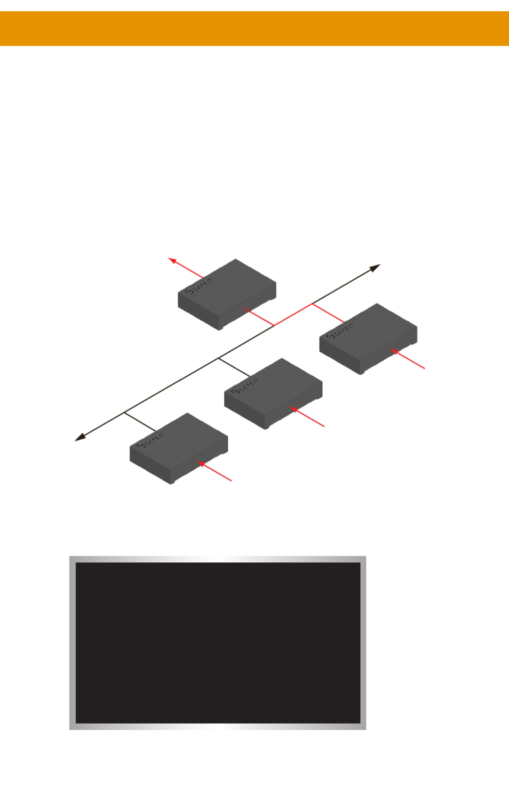
The illustration below shows one Receiver unit and three Sender units. The numbers
indicate the video channel for each unit. Here, the Receiver unit is currently set to
channel 2 and is receiving the signal from the Sender unit, set to channel 2.
To switch the channel, and view the source that is connected to the Sender on channel
5, press and release the button to increment the video channel until the display +/USB
shows the number 5.
LAN
Receiver unit
Out
Sender unit
Sender unit
Sender unit
In
In
In
2
5
1
2
Channel: 05
Setting the Video Channel

31
Blocking & Masking Video
Use the Block Video option on a Sender unit to prevent video from being transmitted to each
of the connected Receiver units (multicast mode only). Use the Mask Video option to selectively
block video on the desired Receiver units.
► Mask Video
1. Access the Web interface of a Receiver unit by entering the IP address in the address bar
of the browser.
2. Login as “Administrator”.
3. Click the tab.Functions
4. Under the Video over IP window group, check the box to mask the video. Mask Enable
Deselect this check box to unmask (enable) video.
5. Click the Apply Video over IP button within the group.
6. Repeat steps 1 through 5 for each Receiver unit in the system.
Produktspecifikationer
| Varumärke: | Gefen |
| Kategori: | Växla |
| Modell: | EXT-UHDKA-LANS-RX |
Behöver du hjälp?
Om du behöver hjälp med Gefen EXT-UHDKA-LANS-RX ställ en fråga nedan och andra användare kommer att svara dig
Växla Gefen Manualer

8 September 2024
4 September 2024
3 September 2024
30 Augusti 2024
29 Augusti 2024
27 Augusti 2024
26 Augusti 2024
25 Augusti 2024
25 Augusti 2024
Växla Manualer
- Växla Bosch
- Växla IKEA
- Växla Huawei
- Växla HP
- Växla Philips
- Växla Panasonic
- Växla Honeywell
- Växla Yamaha
- Växla Abus
- Växla Alcatel
- Växla Alecto
- Växla Apc
- Växla Alpine
- Växla Ansmann
- Växla Airlive
- Växla Edimax
- Växla Intermatic
- Växla Flamingo
- Växla Brennenstuhl
- Växla Hikvision
- Växla Generac
- Växla Silvercrest
- Växla Nedis
- Växla Pyle
- Växla Asus
- Växla Eminent
- Växla Renkforce
- Växla Vivanco
- Växla TP Link
- Växla Manhattan
- Växla Worx
- Växla Black Box
- Växla Elro
- Växla EMOS
- Växla Victron Energy
- Växla KlikaanKlikuit
- Växla Ei Electronics
- Växla Tripp Lite
- Växla DataVideo
- Växla Schneider
- Växla Hama
- Växla Theben
- Växla Elektrobock
- Växla Chamberlain
- Växla Sylvania
- Växla Velleman
- Växla Tork
- Växla Techly
- Växla Sonance
- Växla Emerson
- Växla Totolink
- Växla Vemer
- Växla Smartwares
- Växla Profile
- Växla Cisco
- Växla Matrox
- Växla Steren
- Växla Perel
- Växla Engenius
- Växla IFM
- Växla Digitus
- Växla Kathrein
- Växla AV:link
- Växla Belkin
- Växla Linksys
- Växla Buffalo
- Växla Dahua Technology
- Växla Audiovox
- Växla Cotech
- Växla Netgear
- Växla LevelOne
- Växla Kaiser
- Växla QNAP
- Växla Trotec
- Växla Boss
- Växla Behringer
- Växla PreSonus
- Växla Shimano
- Växla Merten
- Växla Goobay
- Växla Hager
- Växla Mercusys
- Växla Chacon
- Växla Elation
- Växla Sygonix
- Växla Planet
- Växla ZyXEL
- Växla Rex
- Växla Powerfix
- Växla Konig
- Växla Tesla
- Växla D-Link
- Växla Tenda
- Växla UPM
- Växla One For All
- Växla Finder
- Växla Fantini Cosmi
- Växla Audac
- Växla Marmitek
- Växla Delta Dore
- Växla DoorBird
- Växla Ubiquiti Networks
- Växla EBERLE
- Växla Grasslin
- Växla Omnitronic
- Växla Eaton
- Växla Gira
- Växla Jung
- Växla Vacmaster
- Växla CyberPower
- Växla Basetech
- Växla Trendnet
- Växla Mikrotik
- Växla WHALE
- Växla ATen
- Växla Fibaro
- Växla RGBlink
- Växla Nexa
- Växla PAC
- Växla Wentronic
- Växla Dormakaba
- Växla Adder
- Växla Wago
- Växla Homematic IP
- Växla Monoprice
- Växla Tiptel
- Växla OSD Audio
- Växla SPC
- Växla Crestron
- Växla Unify
- Växla ORNO
- Växla Toolcraft
- Växla Berker
- Växla Aeon Labs
- Växla Electro Harmonix
- Växla Grandstream
- Växla Mercury
- Växla Provision ISR
- Växla Monacor
- Växla PCE
- Växla Logilink
- Växla Smart-AVI
- Växla StarTech.com
- Växla SIIG
- Växla Advantech
- Växla IOGEAR
- Växla Merlin Gerin
- Växla Micro Connect
- Växla Extron
- Växla KanexPro
- Växla Intelix
- Växla Blustream
- Växla Avocent
- Växla Shelly
- Växla Intellinet
- Växla Ebode
- Växla Lancom
- Växla Robbe
- Växla ICasa
- Växla B-tech
- Växla Speaka
- Växla Kopp
- Växla Vimar
- Växla Kemo
- Växla GAO
- Växla H-Tronic
- Växla Legrand
- Växla Kraus & Naimer
- Växla Noble
- Växla Intertechno
- Växla Ecler
- Växla Inverto
- Växla Triax
- Växla Rule
- Växla Kramer
- Växla CYP
- Växla Suevia
- Växla Phoenix Contact
- Växla Seuthe
- Växla Maclean Energy
- Växla SmartAVI
- Växla Leviton
- Växla DEHN
- Växla Cudy
- Växla Brilliant
- Växla Heitronic
- Växla Lindy
- Växla SEC24
- Växla Cooking Performance Group
- Växla Ernitec
- Växla Atlona
- Växla Adviti
- Växla Flic
- Växla HELGI
- Växla IB Connect
- Växla Liberty
- Växla PureTools
- Växla Hamlet
- Växla Paladin
- Växla Equip
- Växla Noark
- Växla Vivolink
- Växla Alfatron
- Växla Cambium Networks
- Växla 2USB
- Växla Roline
- Växla KVM-TEC
- Växla AMX
- Växla BZBGear
- Växla STI
- Växla Epiphan
- Växla Ebara
- Växla Mach Power
- Växla Axing
- Växla Juniper
- Växla Raritan
- Växla ConnectPro
- Växla SunBriteTV
- Växla Atlantis Land
- Växla GEV
- Växla Pizzato Elettrica
- Växla Baco
- Växla SEADA
- Växla Doepke
- Växla Comet
- Växla IPGARD
- Växla CSL
- Växla Setti+
- Växla PureLink
- Växla INOGENI
- Växla Luxul
Nyaste Växla Manualer
9 April 2025
9 April 2025
7 April 2025
5 April 2025
5 April 2025
5 April 2025
5 April 2025
3 April 2025
3 April 2025
2 April 2025