Husqvarna Automower 450X EPOS Bruksanvisning
Husqvarna
Robotgräsklippare
Automower 450X EPOS
Läs nedan 📖 manual på svenska för Husqvarna Automower 450X EPOS (40 sidor) i kategorin Robotgräsklippare. Denna guide var användbar för 27 personer och betygsatt med 4.5 stjärnor i genomsnitt av 2 användare
Sida 1/40

EN, English
EN, English
EN, English
EN, EnglishEN, English
Operator's manual
Operator's manual
Operator's manual
Operator's manualOperator's manual
HUSQVARNA AUTOMOWER
HUSQVARNA AUTOMOWER
HUSQVARNA AUTOMOWER
HUSQVARNA AUTOMOWERHUSQVARNA AUTOMOWER®
®
®
®®
450X/450XH EPOS
450X/450XH EPOS
450X/450XH EPOS
450X/450XH EPOS450X/450XH EPOS
Read the operator's manual carefully and make sure that you
Read the operator's manual carefully and make sure that you
Read the operator's manual carefully and make sure that you
Read the operator's manual carefully and make sure that youRead the operator's manual carefully and make sure that you
understand the instructions before you use the product.
understand the instructions before you use the product.
understand the instructions before you use the product.
understand the instructions before you use the product.understand the instructions before you use the product.

1 Safety
1 Safety
1 Safety
1 Safety1 Safety
1.1 Safety definitions
1.1 Safety definitions
1.1 Safety definitions
1.1 Safety definitions1.1 Safety definitions
Warnings, cautions and notes are used to point out
specially important parts of the manual.
WARNING:
WARNING:
WARNING:
WARNING: WARNING: Used if there is a risk of
injury or death for the operator or bystanders
if the instructions in the manual are not
obeyed.
CAUTION:
CAUTION:
CAUTION:
CAUTION: CAUTION: Used if there is a risk of
damage to the product, other materials or
the adjacent area if the instructions in the
manual are not obeyed.
Note:
Note:
Note:
Note: Note: Used to give more information that is necessary
in a given situation.
1.2 General safety instructions
1.2 General safety instructions
1.2 General safety instructions
1.2 General safety instructions1.2 General safety instructions
WARNING:
WARNING:
WARNING:
WARNING: WARNING: Read the warning
instructions that follow before you use the
product.
• Read the Operator’s manual carefully and make
sure you understand the instructions before you
use the product. Keep for future reference.
• This appliance is not intended for use by children
or persons with reduced physical, sensory or
mental capabilities (that could affect a safe
handling of the product), or lack of experience
and knowledge, unless they have been given
supervision or instruction concerning use of the
appliance by a person responsible for their safety.
• The product must only be used with the equipment
recommended Husqvarna. All other types of use
are incorrect.
• Do not use the product when persons, especially
children, or animals are in the work area.
• To prevent damage to the product and accidents to
vehicles and persons, do not install work areas and
transport paths across public pathways.
• Do not use the product in areas where persons are
not aware of the product.
• Warning signs must be put around the work area
of the product if it operates in public areas. The
signs must have the text that follows: Warning!
Automatic lawn mower! Keep away from the
machine! Supervise children!
• Do not run when you operate the product manually
with appDrive. Always walk, be sure on footing
on slopes and make sure to have balance at
all times. Always wear substantial footwear and
long trousers when you operate the product with
appDrive.
• Do not touch moving hazardous parts, such as the
blade disc, before it has come to a complete stop.
• Set the product to OFF before you clear a
blockage, do maintenance or examine the product,
and if the product starts to vibrate abnormally.
Examine the product for damage before you start
the product again. Do not use the product to it is
defective.
• If an injury or accident occur get medical aid.
• Do not install the mains cable in an area where
the product cuts. Follow the instructions to install
the mains cable, refer to
Installation on page 11
.
Installation must be done by service personnel.
• Do not connect a damaged cable or plug, or touch
a damaged cable, before it is disconnected from
the power outlet. Disconnect the plug from the
power outlet if the cable becomes damaged while
in operation. A worn or damaged cable increases
the risk of electrical shock. A damaged cable must
be replaced by service personnel.
• When you connect the mains cable to the power
outlet, use a residual-current device (RCD) with a
tripping current of maximum 30 mA.
• Only charge the product in the included charging
station. For safe disposal of the battery, refer to
Disposal on page 36
. Incorrect use may result in
electric shock, overheating or leaking of corrosive
liquid from the battery. In the event of leakage of
electrolyte, flush with water/neutralizing agent. Get
medical aid if corrosive liquid comes in your eyes.
• Use only original batteries recommended by
Husqvarna. Product safety cannot be guaranteed
with other than original batteries. Do not use non-
rechargeable batteries.
• Follow the installation instructions that includes to
specify the work area and to attach the cutting
deck or other attachments, refer to
Installation on
page 11
.
• Follow the instructions about to start and operate
the product, refer to
Operation on page 22
.
• If there is a risk of thunderstorm, Husqvarna
recommends that the mains cable to the charging
station and the power supply unit to the reference
station are disconnected to decrease the risk of
damage to electrical components. Connect the
mains cable and the power supply again if there
is no longer a risk of thunderstorm.
• Follow the maintenance instructions and if
necessary use Husqvarna original spare parts,
refer to
Maintenance on page 24
.
1970 - 001 - 10.10.2022 Safety - 3
3
3
33

1.7 To lift and move the product
1.7 To lift and move the product
1.7 To lift and move the product
1.7 To lift and move the product1.7 To lift and move the product
To safely move the product from or in the work area the
product can be lifted or operated with appDrive. Refer to
appDrive on page 22
.
WARNING:
WARNING:
WARNING:
WARNING: WARNING: The product must be set to
OFF before you lift the product. The product
is disabled when the is set to
Main switch
Main switch
Main switch
Main switchMain switch
the
0
position.
CAUTION:
CAUTION:
CAUTION:
CAUTION: CAUTION: Do not lift the product when
it is parked in the charging station. It can
cause damage to the charging station and/or
the product. Push the button and
STOP
STOP
STOP
STOPSTOP
pull the product out of the charging station
before you lift it.
1. Push the button to stop the product.
STOP
STOP
STOP
STOP STOP
2. Set the to the
Main switch
Main switch
Main switch
Main switchMain switch
0
position.
3. Lift the product by the handle with the blade disc
away from your body.
1970 - 001 - 10.10.2022 Safety - 5
5
5
55

2 Introduction
2 Introduction
2 Introduction
2 Introduction2 Introduction
Serial number:
Serial number:
Serial number:
Serial number:Serial number:
Product number:
Product number:
Product number:
Product number:Product number:
PIN code:
PIN code:
PIN code:
PIN code:PIN code:
The serial number and the product number are on the product rating plate and on the product carton.
• Register your product on www.husqvarna.com. Enter the serial number of the product, the product number and
the date of purchase to register your product.
2.1 Support
2.1 Support
2.1 Support
2.1 Support2.1 Support
For support about the product, speak to your Husqvarna
servicing dealer.
2.2 System description
2.2 System description
2.2 System description
2.2 System description2.2 System description
The system contains a robotic lawn mower, a charging
station and a reference station. The robotic lawn mower
and reference station uses the technology with satellite
signals to position the robotic lawn mower correctly,
this means that boundary wires are not necessary. The
reference station is stationary and sends correction data
to the robotic lawn mower to get an accurate position
of the robotic lawn mower. The virtual work area for the
product is made in the Automower
® Connect app. The
product is operated and waypoints are added to make a
map in the app. Refer to
System overview on page 7
.
2.3 Product description
2.3 Product description
2.3 Product description
2.3 Product description2.3 Product description
Note:
Note:
Note:
Note: Note: Husqvarna regularly updates the appearance
and function of the products. Refer to
Support on page
6
.
The product is a robotic lawn mower. The product has
a battery power source and cuts grass automatically. It
continuously alternates between mowing and charging.
The movement pattern of the product can be set to
random or systematic. The virtual boundary specifies
the work area where the product is allowed to operate.
The satellite receiver in the product senses when it
is approaching the virtual boundary. When the product
hits an obstacle or approaches the virtual boundary the
product selects a new direction.
The operator selects the operation settings in the
Automower® Connect app. The app shows the selected
and possible operation settings, and the operation mode
of the product.
2.3.1 Mowing technique
2.3.1 Mowing technique
2.3.1 Mowing technique
2.3.1 Mowing technique2.3.1 Mowing technique
The frequent cutting technique improves the grass
quality and decreases the use of fertilizers. Collection
of grass is not necessary.
2.3.2 Find the charging station
2.3.2 Find the charging station
2.3.2 Find the charging station
2.3.2 Find the charging station2.3.2 Find the charging station
The product operates until the battery state of charge
is low or until the work area is cut, then the product
starts to go to the charging station. The product uses
EPOS guidance with satellite signals to find a path to the
charging station. This decreases the wear on the lawn
and the time to find the charging station.
2.3.3 Connectivity
2.3.3 Connectivity
2.3.3 Connectivity
2.3.3 Connectivity2.3.3 Connectivity
Automower® Connect is an app that you can use to
install the product and to select the operation settings
of the product. Refer to
Automower® Connect on page
14
.
6
6
6
66 - Introduction 1970 - 001 - 10.10.2022

>110°
60° 10°
BA
• If the product must not operate in a part of the
docking area, put a protective wall that is minimum
15 cm / 6 in. in height. The docking area (A) is
a circular area around the charging station with a
radius of 3 m / 9.8 ft.
A
Note:
Note:
Note:
Note: Note: The product uses the charging station
signal to search for the charging station when it
is in the docking area.
• Put the charging station near a power outlet.
• Put the charging station on a level surface.
• The baseplate of the charging station must not be
bent.
max. 5 cm / 2"
max. 5 cm / 2"
• If the work area has 2 parts separated with a steep
slope, Husqvarna recommends to put the charging
station in the lower section.
CAUTION:
CAUTION:
CAUTION:
CAUTION: CAUTION: Do not install the charging
station where there are metal objects
in the ground. Metal objects can cause
interference with the charging station signal.
3.6 To examine where to put the power
3.6 To examine where to put the power
3.6 To examine where to put the power
3.6 To examine where to put the power3.6 To examine where to put the power
supply
supply
supply
supplysupply
CAUTION:
CAUTION:
CAUTION:
CAUTION: CAUTION: Make sure that the blades
on the product do not cut the low-voltage
cable.
CAUTION:
CAUTION:
CAUTION:
CAUTION: CAUTION: Do not put the low-voltage
cable in a coil or below the charging station
plate. The coil causes interference with the
signal from the charging station.
• Put the power supply in an area with a roof and
protection from the sun and rain.
• Put the power supply in an area with good airflow.
• Use a residual-current device (RCD) with a tripping
current of maximum 30 mA when you connect the
power supply to the power outlet.
Low-voltage cables of different lengths are available as
accessories.
12
12
12
1212 - Installation 1970 - 001 - 10.10.2022

3.7 To examine where to install the
3.7 To examine where to install the
3.7 To examine where to install the
3.7 To examine where to install the3.7 To examine where to install the
objects on the map
objects on the map
objects on the map
objects on the mapobjects on the map
CAUTION:
CAUTION:
CAUTION:
CAUTION: CAUTION: If the work area is adjacent
to water bodies, slopes, precipices or a
public road, the virtual boundary must have
a protective wall. The wall must be minimum
15 cm / 6 in. in height.
CAUTION:
CAUTION:
CAUTION:
CAUTION: CAUTION: Do not let the product
operate on gravel.
CAUTION:
CAUTION:
CAUTION:
CAUTION: CAUTION: For careful operation
without noise, isolate all obstacles such as
trees, roots and stones.
Note:
Note:
Note:
Note: Note: Make a blueprint of the work area before you
install the virtual boundaries.
• Make sure that the area where the product
operates has unimpeded sky view. This means
that 110° of the sky in all directions must be
unimpeded. The product cannot receive satellite
signals that is less than 10% elevation angle.
>110°
35° 35°
60°
10°
>110°
• Make sure that there are no trees near the virtual
boundaries and along the paths.
• Make sure that there are no trees with thick
vegetation in the areas where the product
operates.
• Make sure that the product can receive radio
signals from the reference station in all parts of
the work area. The maximum distance between the
reference station and the product is 500 m / 1640
ft. The maximum distance decreases if there is
objects between the reference station and product.
3.7.1 Passages
3.7.1 Passages
3.7.1 Passages
3.7.1 Passages3.7.1 Passages
A passage is a section that has virtual boundary on
each side and that connects 2 parts of the work area.
The passage must be a minimum of 2 m / 6.5 ft. wide
to get a good cutting result. Short passages can be as
narrow as 1 m / 3.3 ft. A long narrow passage can have
a negative impact of the cutting result. A dead end must
be a minimum of 2 m / 6.5 ft. wide.
3.7.2 To install the map objects in a slope
3.7.2 To install the map objects in a slope
3.7.2 To install the map objects in a slope
3.7.2 To install the map objects in a slope3.7.2 To install the map objects in a slope
The product can operate in 45% slopes. Do not include
too steep slopes in the work area. Too steep slopes
can be isolated as stay-out zones. The slope (%) is
calculated as height for each m. Example: 10 cm / 100
cm = 10%.
10 cm/4"
100 cm/40"
10%
• For slopes more than 45% in the work area, isolate
the slope with a stay-out zone.
• For slopes that are more than 15% along the outer
edge of the lawn. For installation of the virtual
boundary, operate the product with the rear wheel
5 cm / 2 in. (A) from the edge.
A
• For slopes adjacent to a public road, put a fence or
a protective wall along the outer edge of the slope.
3.8 Installation of the product
3.8 Installation of the product
3.8 Installation of the product
3.8 Installation of the product3.8 Installation of the product
3.8.1 To install the product
3.8.1 To install the product
3.8.1 To install the product
3.8.1 To install the product3.8.1 To install the product
Do the general steps that follow to install the product:
1970 - 001 - 10.10.2022 Installation - 13
13
13
1313

1. Install the reference station. Refer to the
Operator's manual for the reference station.
2. Install the charging station. Refer to
To install the
charging station on page 14
.
3. Install the Automower® Connect app on your
mobile device. Refer to
To install the Automower®
Connect app on page 15
.
4. Do a pairing operation of the product and the
Automower® Connect app. Do the basic settings in
the start up sequence in the Automower
® Connect
app. Refer to
To install the Automower® Connect
app on page 15
.
5. Make a map with work areas, stay-out zones,
transport paths and maintenance points. Refer to
To install objects on the map on page 16
.
6. Use Automower
® Connect app to do settings for
the product. Refer to
Settings on page 18
.
3.8.2 Installation tools
3.8.2 Installation tools
3.8.2 Installation tools
3.8.2 Installation tools3.8.2 Installation tools
• Hex key, 8 mm. Included in the carton.
3.8.3 Installation of the charging station
3.8.3 Installation of the charging station
3.8.3 Installation of the charging station
3.8.3 Installation of the charging station3.8.3 Installation of the charging station
Read and understand the instructions about the
charging station. Refer to
To examine where to put the
charging station on page 11
.
CAUTION:
CAUTION:
CAUTION:
CAUTION: CAUTION: Do not make new holes in
the charging station plate.
CAUTION:
CAUTION:
CAUTION:
CAUTION: CAUTION: Do not put your feet on the
baseplate of the charging station.
WARNING:
WARNING:
WARNING:
WARNING: WARNING: Make sure that the plugs of
the low-voltage cable and the power supply
unit are clean and dry before you connect
them.
When you connect the power supply, only use a power
outlet that is connected to a residual-current device
(RCD).
3.8.3.1 To install the charging station
3.8.3.1 To install the charging station
3.8.3.1 To install the charging station
3.8.3.1 To install the charging station3.8.3.1 To install the charging station
1. Put the charging station in the selected area.
2. Attach the charging station to the ground with the
supplied screws.
3. Connect the low-voltage cable to the charging
station.
4. Put the power supply at a minimum height of 30
cm / 12 in. Refer to
To examine where to put the
power supply on page 12
.
min 30 cm / 12”
5. Connect the power supply cable to a 100-240V
power outlet.
6. Put the low-voltage cable in the ground outside the
work area. Use stakes or bury the cable.
7. Put the product in the charging station to charge
the product.
3.8.3.2 To do a visual check of the charging station
3.8.3.2 To do a visual check of the charging station
3.8.3.2 To do a visual check of the charging station
3.8.3.2 To do a visual check of the charging station3.8.3.2 To do a visual check of the charging station
1. Make sure that the indicator LED lamp on the
charging station has a green light.
2. If the indicator LED lamp does not have a green
light, do a check of the installation. Refer to
To
install the charging station on page 14
and
LED
indicator lamp on the charging station on page
33
.
3.8.4 Installation of the reference station
3.8.4 Installation of the reference station
3.8.4 Installation of the reference station
3.8.4 Installation of the reference station3.8.4 Installation of the reference station
Install the reference station according to the instructions
in the Operator's manual for the reference station.
3.8.5 Automower
3.8.5 Automower
3.8.5 Automower
3.8.5 Automower3.8.5 Automower®
®
®
®® Connect
Connect
Connect
Connect Connect
Automower® Connect is a free app for your mobile
device. Use the app for installation, settings and
operation of your product. You can also find more
information for example about alarm and statistics in the
Automower® Connect app.
The app gives 2 modes of connectivity: Long-
range cellular connectivity and Short-range Bluetooth
®
connectivity.
• Dashboard that shows the current status of the
product and the battery state of charge.
• Account shows an overview of the account settings
and the unit format can be set.
14
14
14
1414 - Installation 1970 - 001 - 10.10.2022

• Operate the product counterclockwise around the
boundary of the stay-out zone.
• Add waypoints on the map. Add the waypoints
minimum 3 cm / 1 in. from obstacles.
• Do not set waypoints that make a virtual boundary
go across itself in the same stay-out zone.
• Save the work area to automatically connect the
first and last waypoint with a virtual boundary.
To make a transport path
To make a transport path
To make a transport path
To make a transport pathTo make a transport path
• Operate the product and add waypoints on the
map to install a transport path. Start in a work area
minimum 1 m / 3.3 ft. from the virtual boundary.
• Do not install a transport path across a stay-out
zone.
• Do not set waypoints that make the transport path
go across the same transport path.
• Operate the product and add waypoints to connect
the transport path to the docking point.
• Save the transport path to automatically connect
the last waypoint to the docking point.
• Set the corridor width (A) for the transport path.
The corridor width can be set to 2-5 m / 6.6-16.4 ft.
A
To make a maintenance point
To make a maintenance point
To make a maintenance point
To make a maintenance pointTo make a maintenance point
• Operate the product and add waypoints on the
map. Start to add waypoints at the position
where you install the maintenance point. The first
waypoint specifies the maintenance point.
• Operate the product and add waypoints to make a
path to the charging station.
• Save the maintenance point to automatically
connect the last waypoint to the docking point.
• Set the corridor width (A) for the maintenance
point. The corridor width can be set to 2-5 m /
6.6-16.4 ft.
A
3.9 Settings
3.9 Settings
3.9 Settings
3.9 Settings3.9 Settings
The product has factory settings but the settings can be
adapted to each work area.
3.9.1 Schedule
3.9.1 Schedule
3.9.1 Schedule
3.9.1 Schedule3.9.1 Schedule
In
Schedule
menu you can change the schedule settings
for the product. The
Schedule
is set for each work area
that is connected to the charging station.
Secondary
areas
cannot be scheduled.
The schedule function controls which hours the product
is permitted to operate. When the product does not
operate it is parked in the charging station. You can
see which hours and days the product operates in the
schedule overview in the app.
The factory schedule setting lets the product to operate
around the clock 7 days a week.
To calculate the schedule setting, refer to
To calculate
the schedule setting on page 18
.
3.9.1.1 To calculate the schedule setting
3.9.1.1 To calculate the schedule setting
3.9.1.1 To calculate the schedule setting
3.9.1.1 To calculate the schedule setting3.9.1.1 To calculate the schedule setting
1. Calculate the dimension of your lawn in m
2 / ft2.
2. Divide the m2 / ft2 of the lawn with the approximate
operation capacity. Refer to table below.
3. The result is equal to the number of hours that the
product must operate each day.
18
18
18
1818 - Installation 1970 - 001 - 10.10.2022

product is paused until either
Park
or
Start
is selected
in the Automower® Connect app.
4.5 To stop the product
4.5 To stop the product
4.5 To stop the product
4.5 To stop the product4.5 To stop the product
1. Push the button on top of the product.
STOP
STOP
STOP
STOPSTOP
The product stops and the cutting motor stops.
Note:
Note:
Note:
Note: Note: When you push the button again, the
START
START
START
STARTSTART
product continues to operate in the same operating
mode as before.
4.6 To set the product to OFF
4.6 To set the product to OFF
4.6 To set the product to OFF
4.6 To set the product to OFF4.6 To set the product to OFF
1. Push the button.
STOP
STOP
STOP
STOPSTOP
2. Connect the product with Bluetooth
® short-range in
the app.
Note:
Note:
Note:
Note: Note: The product cannot be set to OFF if it is
not connected to the app with Bluetooth
®.
3. Set the to the
Main switch
Main switch
Main switch
Main switchMain switch
0
position.
4.7 To charge the battery
4.7 To charge the battery
4.7 To charge the battery
4.7 To charge the battery4.7 To charge the battery
When the product is new or after long-term storage, the
battery can be empty. Charge the battery before you
start the product.
1. Set the to the
Main switch
Main switch
Main switch
Main switchMain switch
1
position.
2. Put the product into the charging station until the
charging plates touch the contact plates.
3. Do a check that the product charges in the
Automower® Connect app.
1970 - 001 - 10.10.2022 Operation - 23
23
23
2323
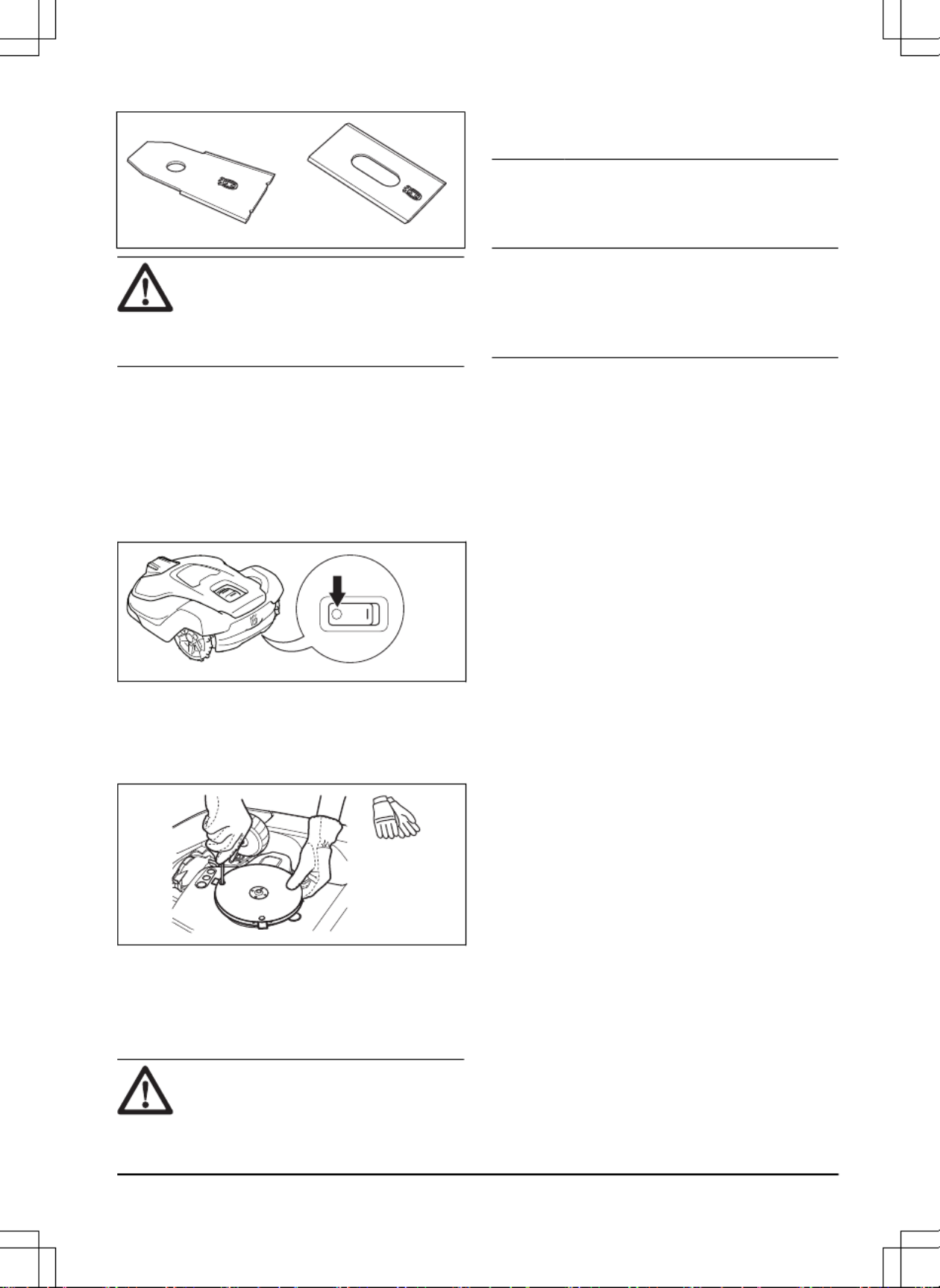
WARNING:
WARNING:
WARNING:
WARNING: WARNING: You must replace the
screws when you replace the blades. The
used screws can wear quickly and make the
blade come loose, this can cause serious
injury.
Replace worn or damaged blades for a safe operation.
Replace the blades regularly for a satisfactory cut result
and a low energy use. All 3 blades and screws must
be replaced at the same time to get a balanced cutting
system.
5.3.1 To replace the blades
5.3.1 To replace the blades
5.3.1 To replace the blades
5.3.1 To replace the blades5.3.1 To replace the blades
1. Push the button.
STOP
STOP
STOP
STOPSTOP
2. Set the to the
Main switch
Main switch
Main switch
Main switchMain switch
0
position.
3. Put the product with the blade disc up on a soft
and clean surface.
4. Rotate the skid plate until its holes align with the
screws for the blade.
5. Remove the 3 screws with a screwdriver.
6. Remove the 3 blades.
7. Attach 3 new blades and screws.
8. Make sure that the blades can pivot freely.
5.4 Battery
5.4 Battery
5.4 Battery
5.4 Battery5.4 Battery
CAUTION:
CAUTION:
CAUTION:
CAUTION: CAUTION: Charge the battery fully
before you put the product into storage. If
the battery is not fully charged it can cause
damage to the battery.
If the operating time of the product is shorter than usual
between charges, this means that the battery is at the
end of its life cycle. Replace the battery to extend the
operating time.
Note:
Note:
Note:
Note: Note: The battery life is related to the length of
the season and how many hours a day the product
operates. A long season or many hours of operation
a day means that the battery must be replaced more
regularly.
5.5 Winter service
5.5 Winter service
5.5 Winter service
5.5 Winter service5.5 Winter service
Take your product to your Husqvarna central service for
service prior to winter storage. Regular winter service
will maintain the product in good condition and create
the best conditions for a new season without any
disruptions.
Service usually includes the following:
• Thorough cleaning of the body, the chassis, the
blade disc and all other moving parts.
• Testing of the product’s function and components.
• Checking and, if required, replacing wear items
such as blades and bearings.
• Testing the product’s battery capacity as well as a
recommendation to replace battery if necessary.
• If new firmware is available, the product is
updated.
1970 - 001 - 10.10.2022 Maintenance - 25
25
25
2525

Message
Message
Message
MessageMessage Cause
Cause
Cause
CauseCause Action
Action
Action
ActionAction
Map problem
There is no specified work area. Make a work area in the Automower
®
Connect app. Refer to
To make a work
area on page 17
.
The charging station or the reference sta-
tion was moved.
Move the charging station or the refer-
ence station to their initial positions.
Do a new installation of the map.
The map object file is incorrect. Do a check of the map in the app. Adjust
the map and save it.
Delete the map and do a new installation.
Wheel drive problem, right/
left
The wheel is blocked by grass or other
objects.
Examine the drive wheel and remove
grass or other objects.
Searching for position
Weak satellite signal to the reference sta-
tion.
The satellite signal is temporary weak.
The product will start to operate when the
satellite signals are good.
Examine the installation of the reference
station. Refer to the Operator's manual
for the Reference station.
Weak satellite signal to the product. The satellite signal is temporary weak.
The product will start to operate when the
satellite signal are good.
Examine if there is an object between
the product and the sky that cause inter-
ference with the satellite signal. Remove
the object or do a new installation to not
include these parts in the work area. Re-
fer to
Installation of the map objects on
page 15
No accurate position from
satellites
Weak satellite signal to the reference sta-
tion.
Examine the installation of the reference
station. Refer to the Operator's manual
for the Reference station.
Weak satellite signal to the product. Examine if there is an object between
the product and the sky that cause inter-
ference with the satellite signal. Remove
the object or do a new installation to not
include these parts in the work area. Re-
fer to
To make a work area on page 17
30
30
30
3030 - Troubleshooting 1970 - 001 - 10.10.2022
Produktspecifikationer
| Varumärke: | Husqvarna |
| Kategori: | Robotgräsklippare |
| Modell: | Automower 450X EPOS |
Behöver du hjälp?
Om du behöver hjälp med Husqvarna Automower 450X EPOS ställ en fråga nedan och andra användare kommer att svara dig
Robotgräsklippare Husqvarna Manualer

12 Mars 2025
12 Mars 2025
11 Februari 2025
7 September 2024
30 Augusti 2024
29 Augusti 2024
25 Augusti 2024
13 Augusti 2024
13 Augusti 2024
13 Augusti 2024
Robotgräsklippare Manualer
- Robotgräsklippare Al-ko
- Robotgräsklippare Ambrogio
- Robotgräsklippare Black And Decker
- Robotgräsklippare Worx
- Robotgräsklippare Ezviz
- Robotgräsklippare Einhell
- Robotgräsklippare Gardena
- Robotgräsklippare Yard Force
- Robotgräsklippare Robomow
- Robotgräsklippare Flymo
- Robotgräsklippare Stiga
- Robotgräsklippare McCulloch
- Robotgräsklippare Clas Ohlson
- Robotgräsklippare Kress
- Robotgräsklippare Greenworks
- Robotgräsklippare Anova
- Robotgräsklippare Mastech
Nyaste Robotgräsklippare Manualer
20 Februari 2025
2 Januari 2025
31 December 2025
21 December 2024
21 December 2024
18 December 2024
11 December 2024
13 Oktober 2024
27 September 2024
26 September 2024