Lenovo BladeCenter HS22 Bruksanvisning
Läs nedan 📖 manual på svenska för Lenovo BladeCenter HS22 (112 sidor) i kategorin Server. Denna guide var användbar för 16 personer och betygsatt med 4.5 stjärnor i genomsnitt av 2 användare
Sida 1/112

BladeCenter HS22
Type 7870, 1936, and 1911
Installation and User's Guide


BladeCenter HS22
Type 7870, 1936, and 1911
Installation and User's Guide

Note: Before using this information and the product it supports, read the general information in
“Notices” on page 83 and the , ,Safety Information Environmental Notices and User Guide Warranty
Information Documentationdocuments on the IBM CD.
The most recent version of this document is available at http://www.ibm.com/systems/support/.
Thirteenth Edition (August 2012)
© Copyright IBM Corporation 2012.
US Government Users Restricted Rights – Use, duplication or disclosure restricted by GSA ADP Schedule Contract
with IBM Corp.

Contents
Safety . . . . . . . . . . . . . . . v
Guidelines for trained technicians . . . . . . . vi
Inspecting for unsafe conditions . . . . . . vi
Guidelines for servicing electrical equipment . . vii
Safety statements . . . . . . . . . . . . viii
Chapter 1. Introduction . . . . . . . . 1
Related documentation . . . . . . . . . . . 4
The IBM Documentation CD . . . . . . . . . 5
Hardware and software requirements . . . . . 5
Using the Documentation Browser . . . . . . 5
Notices and statements in this document . . . . . 6
Features and specifications. . . . . . . . . . 7
What your blade server offers . . . . . . . . 9
Reliability, availability, and serviceability features. . 11
IBM Director . . . . . . . . . . . . . . 12
Major components of the blade server . . . . . 13
Chapter 2. Power, controls, and
indicators . . . . . . . . . . . . . 15
Blade server controls and LEDs. . . . . . . . 15
Turning on the blade server . . . . . . . . 18
Turning off the blade server . . . . . . . . 18
Blade server connectors . . . . . . . . . 19
BladeCenter GPU expansion unit LED . . . . . 19
Chapter 3. Installing options . . . . . 21
Installation guidelines . . . . . . . . . . . 21
System reliability guidelines . . . . . . . . 22
Handling static-sensitive devices . . . . . . 22
Removing the blade server from the BladeCenter
unit . . . . . . . . . . . . . . . . . 23
Removing the blade server cover . . . . . . . 24
Installing an optional expansion unit . . . . . . 25
Removing an optional expansion unit . . . . . 26
Installing a hot-swap storage drive . . . . . . 27
Removing a hot-swap storage drive . . . . . . 28
Installing a memory module. . . . . . . . . 29
Removing a memory module . . . . . . . . 33
Installing a GPU adapter in the BladeCenter GPU
expansion unit . . . . . . . . . . . . . 34
Removing a GPU adapter from the BladeCenter
GPU expansion unit . . . . . . . . . . . 36
Installing a microprocessor and heat sink . . . . 39
Thermal grease . . . . . . . . . . . . . 42
Installing a USB Flash key . . . . . . . . . 43
I/O expansion cards . . . . . . . . . . . 44
Installing a horizontal-compact-form-factor
expansion card . . . . . . . . . . . . 45
Removing a horizontal-compact-form-factor
expansion card . . . . . . . . . . . . 46
Installing a CIOv-form-factor expansion card . . 47
Removing a CIOv-form-factor expansion card . . 48
Installing a storage interface card . . . . . . 49
Removing a storage interface card . . . . . . 52
Completing the installation . . . . . . . . . 54
Closing the blade server cover . . . . . . . 55
Installing the blade server in a BladeCenter unit 56
Updating the blade server configuration . . . . 58
Input/output connectors and devices. . . . . . 58
Chapter 4. Configuring the blade server 59
Using the Setup utility. . . . . . . . . . . 60
Setup utility menu . . . . . . . . . . . 60
Using passwords . . . . . . . . . . . 63
Using the ServerGuide Setup and Installation CD . 63
ServerGuide features . . . . . . . . . . 64
Setup and configuration overview . . . . . . 64
Typical operating-system installation . . . . . 65
Installing the operating system without using
ServerGuide . . . . . . . . . . . . . 65
Using the PXE boot agent utility program . . . . 66
Firmware updates . . . . . . . . . . . . 66
Configuring UEFI compatible devices . . . . . 66
Configuring the Gigabit Ethernet controller. . . . 67
Configuring a RAID array . . . . . . . . . 67
Using the LSI Logic Configuration Utility program 68
Using LAN over USB to interface the IMM . . . . 68
Potential conflicts with the LAN over USB
interface . . . . . . . . . . . . . . 69
Resolving conflicts with the IMM LAN over USB
interface . . . . . . . . . . . . . . 69
Configuring the LAN over USB interface
manually . . . . . . . . . . . . . . 70
Chapter 5. Installing the operating
system. . . . . . . . . . . . . . . 73
Using the ServerGuide Setup and Installation CD to
install the operating system . . . . . . . . . 73
Using RDM to install the operating system . . . . 74
Downloading installation instructions . . . . . 74
Chapter 6. Solving problems . . . . . 75
Diagnostic tools overview . . . . . . . . . 75
ServerGuide problems . . . . . . . . . . . 76
Appendix. Getting help and technical
assistance . . . . . . . . . . . . . 79
Before you call . . . . . . . . . . . . . 79
Using the documentation . . . . . . . . . . 80
Getting help and information from the World Wide
Web . . . . . . . . . . . . . . . . . 80
How to send DSA data to IBM . . . . . . . . 80
Creating a personalized support web page . . . . 80
Software service and support . . . . . . . . 81
Hardware service and support . . . . . . . . 81
IBM Taiwan product service . . . . . . . . . 81
Notices . . . . . . . . . . . . . . 83
© Copyright IBM Corp. 2012 iii

Trademarks . . . . . . . . . . . . . . 83
Important notes . . . . . . . . . . . . . 84
Particulate contamination. . . . . . . . . . 85
Documentation format. . . . . . . . . . . 86
Telecommunication regulatory statement . . . . 86
Electronic emission notices . . . . . . . . . 86
Federal Communications Commission (FCC)
statement . . . . . . . . . . . . . . 86
Industry Canada Class A emission compliance
statement . . . . . . . . . . . . . . 87
Avis de conformité à la réglementation
d'Industrie Canada . . . . . . . . . . . 87
Australia and New Zealand Class A statement . 87
European Union EMC Directive conformance
statement . . . . . . . . . . . . . . 87
Germany Class A statement . . . . . . . . 87
Japan VCCI Class A statement . . . . . . . 88
Japan Electronics and Information Technology
Industries Association (JEITA) statement. . . . 89
Korea Communications Commission (KCC)
statement . . . . . . . . . . . . . . 89
Russia Electromagnetic Interference (EMI) Class
A statement . . . . . . . . . . . . . 89
People's Republic of China Class A electronic
emission statement . . . . . . . . . . . 89
Taiwan Class A compliance statement . . . . 90
Index . . . . . . . . . . . . . . . 91
iv BladeCenter HS22 Type 7870, 1936, and 1911: Installation and User's Guide

Safety
Before installing this product, read the Safety Information.
Antes de instalar este produto, leia as Informações de Segurança.
Læs sikkerhedsforskrifterne, før du installerer dette produkt.
Lees voordat u dit product installeert eerst de veiligheidsvoorschriften.
Ennen kuin asennat tämän tuotteen, lue turvaohjeet kohdasta Safety Information.
Avant d'installer ce produit, lisez les consignes de sécurité.
Vor der Installation dieses Produkts die Sicherheitshinweise lesen.
Prima di installare questo prodotto, leggere le Informazioni sulla Sicurezza.
© Copyright IBM Corp. 2012 v

Les sikkerhetsinformasjonen (Safety Information) før du installerer dette produktet.
Antes de instalar este produto, leia as Informações sobre Segurança.
Antes de instalar este producto, lea la información de seguridad.
Läs säkerhetsinformationen innan du installerar den här produkten.
Guidelines for trained technicians
This section contains information for trained technicians.
Inspecting for unsafe conditions
Use this information to help you identify potential unsafe conditions in an IBM®
product that you are working on.
Each IBM product, as it was designed and manufactured, has required safety items
to protect users and service technicians from injury. The information in this section
addresses only those items. Use good judgment to identify potential unsafe
conditions that might be caused by non-IBM alterations or attachment of non-IBM
features or optional devices that are not addressed in this section. If you identify
vi BladeCenter HS22 Type 7870, 1936, and 1911: Installation and User's Guide

an unsafe condition, you must determine how serious the hazard is and whether
you must correct the problem before you work on the product.
Consider the following conditions and the safety hazards that they present:
vElectrical hazards, especially primary power. Primary voltage on the frame can
cause serious or fatal electrical shock.
vExplosive hazards, such as a damaged CRT face or a bulging capacitor.
vMechanical hazards, such as loose or missing hardware.
To inspect the product for potential unsafe conditions, complete the following
steps:
1. Make sure that the power is off and the power cords are disconnected.
2. Make sure that the exterior cover is not damaged, loose, or broken, and observe
any sharp edges.
3. Check the power cords:
vMake sure that the third-wire ground connector is in good condition. Use a
meter to measure third-wire ground continuity for 0.1 ohm or less between
the external ground pin and the frame ground.
vMake sure that the power cords are the correct type.
vMake sure that the insulation is not frayed or worn.
4. Remove the cover.
5. Check for any obvious non-IBM alterations. Use good judgment as to the safety
of any non-IBM alterations.
6. Check inside the system for any obvious unsafe conditions, such as metal
filings, contamination, water or other liquid, or signs of fire or smoke damage.
7. Check for worn, frayed, or pinched cables.
8. Make sure that the power-supply cover fasteners (screws or rivets) have not
been removed or tampered with.
Guidelines for servicing electrical equipment
Observe these guidelines when you service electrical equipment.
vCheck the area for electrical hazards such as moist floors, nongrounded power
extension cords, and missing safety grounds.
vUse only approved tools and test equipment. Some hand tools have handles that
are covered with a soft material that does not provide insulation from live
electrical current.
vRegularly inspect and maintain your electrical hand tools for safe operational
condition. Do not use worn or broken tools or testers.
vDo not touch the reflective surface of a dental mirror to a live electrical circuit.
The surface is conductive and can cause personal injury or equipment damage if
it touches a live electrical circuit.
vSome rubber floor mats contain small conductive fibers to decrease electrostatic
discharge. Do not use this type of mat to protect yourself from electrical shock.
vDo not work alone under hazardous conditions or near equipment that has
hazardous voltages.
vLocate the emergency power-off (EPO) switch, disconnecting switch, or electrical
outlet so that you can turn off the power quickly in the event of an electrical
accident.
vDisconnect all power before you perform a mechanical inspection, work near
power supplies, or remove or install main units.
Safety vii

vBefore you work on the equipment, disconnect the power cord. If you cannot
disconnect the power cord, have the customer power-off the wall box that
supplies power to the equipment and lock the wall box in the off position.
vNever assume that power has been disconnected from a circuit. Check it to
make sure that it has been disconnected.
vIf you have to work on equipment that has exposed electrical circuits, observe
the following precautions:
– Make sure that another person who is familiar with the power-off controls is
near you and is available to turn off the power if necessary.
– When you work with powered-on electrical equipment, use only one hand.
Keep the other hand in your pocket or behind your back to avoid creating a
complete circuit that could cause an electrical shock.
– When you use a tester, set the controls correctly and use the approved probe
leads and accessories for that tester.
– Stand on a suitable rubber mat to insulate you from grounds such as metal
floor strips and equipment frames.
vUse extreme care when you measure high voltages.
vTo ensure proper grounding of components such as power supplies, pumps,
blowers, fans, and motor generators, do not service these components outside of
their normal operating locations.
vIf an electrical accident occurs, use caution, turn off the power, and send another
person to get medical aid.
Safety statements
These statements provide the caution and danger information that is used in this
documentation.
Important:
Each caution and danger statement in this documentation is labeled with a
number. This number is used to cross reference an English-language caution or
danger statement with translated versions of the caution or danger statement in
the document.Safety Information
For example, if a caution statement is labeled “Statement 1,” translations for that
caution statement are in the document under “Statement 1.”Safety Information
Be sure to read all caution and danger statements in this documentation before you
perform the procedures. Read any additional safety information that comes with
your system or optional device before you install the device.
Statement 1
viii BladeCenter HS22 Type 7870, 1936, and 1911: Installation and User's Guide

DANGER
Electrical current from power, telephone, and communication cables is
hazardous.
To avoid a shock hazard:
vDo not connect or disconnect any cables or perform installation,
maintenance, or reconfiguration of this product during an electrical storm.
vConnect all power cords to a properly wired and grounded electrical outlet.
vConnect to properly wired outlets any equipment that will be attached to
this product.
vWhen possible, use one hand only to connect or disconnect signal cables.
vNever turn on any equipment when there is evidence of fire, water, or
structural damage.
vDisconnect the attached power cords, telecommunications systems,
networks, and modems before you open the device covers, unless
instructed otherwise in the installation and configuration procedures.
vConnect and disconnect cables as described in the following table when
installing, moving, or opening covers on this product or attached devices.
To Connect: To Disconnect:
1. Turn everything OFF.
2. First, attach all cables to devices.
3. Attach signal cables to connectors.
4. Attach power cords to outlet.
5. Turn device ON.
1. Turn everything OFF.
2. First, remove power cords from outlet.
3. Remove signal cables from connectors.
4. Remove all cables from devices.
Statement 2
CAUTION:
When replacing the lithium battery, use only IBM Part Number 33F8354 or an
equivalent type battery recommended by the manufacturer. If your system has a
module containing a lithium battery, replace it only with the same module type
made by the same manufacturer. The battery contains lithium and can explode if
not properly used, handled, or disposed of.
Do not:
vThrow or immerse into water
vHeat to more than 100°C (212°F)
vRepair or disassemble
Dispose of the battery as required by local ordinances or regulations.
Safety ix

Statement 3
CAUTION:
When laser products (such as CD-ROMs, DVD drives, fiber optic devices, or
transmitters) are installed, note the following:
vDo not remove the covers. Removing the covers of the laser product could
result in exposure to hazardous laser radiation. There are no serviceable parts
inside the device.
vUse of controls or adjustments or performance of procedures other than those
specified herein might result in hazardous radiation exposure.
DANGER
Some laser products contain an embedded Class 3A or Class 3B laser diode.
Note the following.
Laser radiation when open. Do not stare into the beam, do not view directly
with optical instruments, and avoid direct exposure to the beam.
Statement 4
≥≥≥18 kg (39.7 lb) 32 kg (70.5 lb) 55 kg (121.2 lb)
CAUTION:
Use safe practices when lifting.
xBladeCenter HS22 Type 7870, 1936, and 1911: Installation and User's Guide

Statement 8
CAUTION:
Never remove the cover on a power supply or any part that has the following
label attached.
Hazardous voltage, current, and energy levels are present inside any component
that has this label attached. There are no serviceable parts inside these
components. If you suspect a problem with one of these parts, contact a service
technician.
Statement 12
CAUTION:
The following label indicates a hot surface nearby.
Statement 13
Safety xi

DANGER
Overloading a branch circuit is potentially a fire hazard and a shock hazard
under certain conditions. To avoid these hazards, ensure that your system
electrical requirements do not exceed branch circuit protection requirements.
Refer to the information that is provided with your device for electrical
specifications.
Statement 21
CAUTION:
Hazardous energy is present when the blade is connected to the power source.
Always replace the blade cover before installing the blade.
Statement 32
CAUTION:
To avoid personal injury, before lifting the unit, remove all the blades, power
supplies, and removable modules to reduce the weight.
Statement 33
CAUTION:
This device does not provide a power control button. Removing power supply
modules or turning off the server blades does not turn off the electrical current
supplied to the device. The device also might have more than one power cord.
To remove all electrical current from the device, ensure that all power cords are
disconnected from the power source.
xii BladeCenter HS22 Type 7870, 1936, and 1911: Installation and User's Guide

Rack Safety Information, Statement 2
DANGER
vAlways lower the leveling pads on the rack cabinet.
vAlways install stabilizer brackets on the rack cabinet.
vAlways install servers and optional devices starting from the bottom of the
rack cabinet.
vAlways install the heaviest devices in the bottom of the rack cabinet.
UL regulatory information
This device is for use only with supported blade chassis.
Safety xiii

xiv BladeCenter HS22 Type 7870, 1936, and 1911: Installation and User's Guide

Chapter 1. Introduction
The IBM BladeCenter®HS22 Type 7870, 1936, and 1911 blade server is compatible
with IBM BladeCenter units. This high density, high performance, single-wide
blade server is ideally suited for medium and large businesses. The IBM
BladeCenter HS22 blade server supports up to two multi-core Intel Xeon
microprocessors and has twelve memory-module slots, two hot-swappable
storage-device bays, one Horizontal-compact-form-factor (CFFh) expansion card
connector, one Vertical-combination-I/O (CIOv) connector, and one internal USB
connector.
Note: Unless otherwise stated, references to the BladeCenter unit apply to all
BladeCenter unit types.
This provides information about:Installation and User's Guide
vSetting up the blade server
vStarting and configuring the blade server
vInstalling hardware options
vInstalling the operating system
vPerforming basic troubleshooting of the blade server
Packaged with this document are software CDs that help you to configure
hardware, install device drivers, and install the operating system.
To download the latest device drivers, complete the following steps.
Note: Changes are made periodically to the IBM Web site. The actual procedure
might vary slightly from what is described in this document.
1. Go to http://www.ibm.com/systems/support/.
2. Under , click .Product support BladeCenter
3. Under , click .Popular links Software and device drivers
4. Click to display the matrix of downloadable files for theBladeCenter HS22
blade server.
The blade server comes with a limited warranty. For information about the terms
of the warranty and getting service and assistance, see the Warranty and Support
Information Documentationdocument for your blade server on the IBM CD. You can
obtain up-to-date information about the blade server at http://www.ibm.com/
systems/bladecenter/.
If firmware and documentation updates are available, you can download them
from the IBM Web site. The blade server might have features that are not described
in the documentation that comes with the blade server, and the documentation
might be updated occasionally to include information about those features, or
technical updates might be available to provide additional information that is not
included in the blade server documentation.
© Copyright IBM Corp. 2012 1

To check for updates, complete the following steps.
Note: Changes are made periodically to the IBM Web site. Procedures for locating
firmware and documentation might change from what is described in this
document.
1. Go to http://www.ibm.com/systems/support/.
2. Under , click .Product support BladeCenter
3. Under , click for firmware updates,Popular links Software and device drivers
or click for documentation updates.Publications lookup
You can subscribe to information updates specific to your blade server at
http://www.ibm.com/support/mynotifications.
Note: The illustrations in this document might differ slightly from the hardware.
The following illustration shows an IBM BladeCenter H22 blade server.
The following illustration shows an IBM BladeCenter H22 Type 1911 blade server
that features four BladeCenter GPU expansion units.
2BladeCenter HS22 Type 7870, 1936, and 1911: Installation and User's Guide
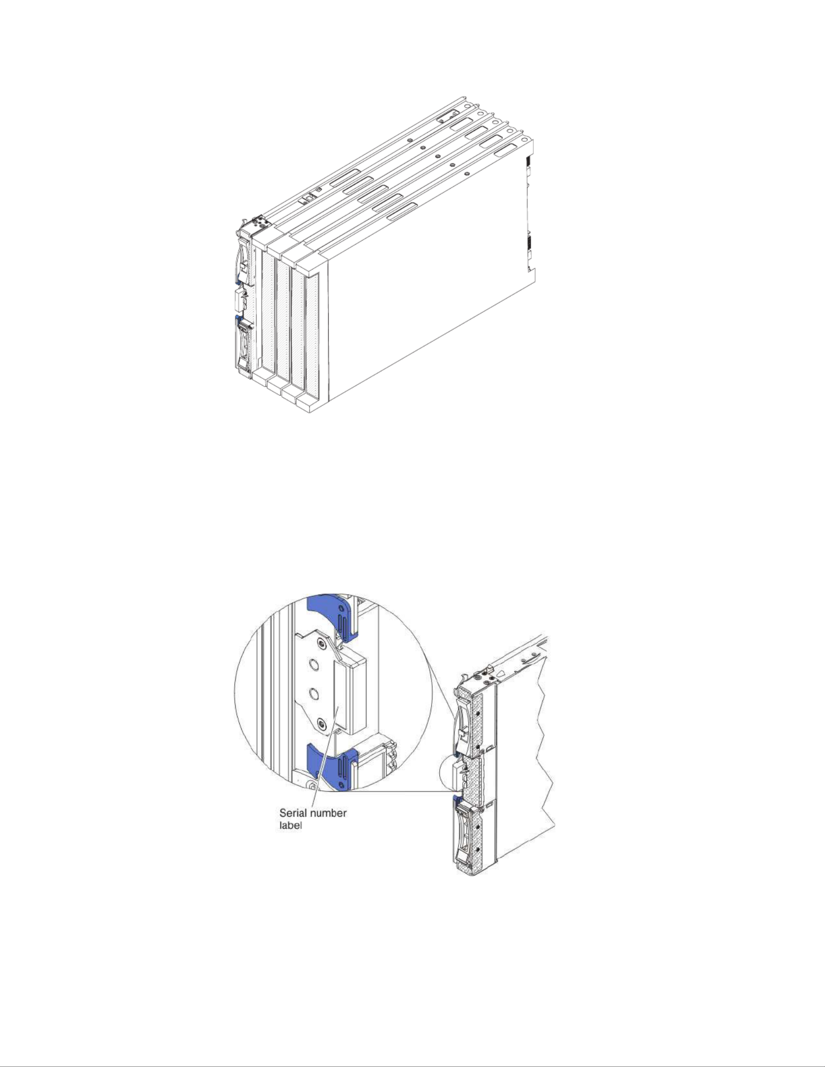
The model number and serial number are on the ID label on the side of the control
panel on the front of the blade server, and on a label on the side of the blade
server that is visible when the blade server is not in the BladeCenter unit.
Note: The illustrations in this document might differ slightly from the hardware.
Important: Do not place the label on the blade server itself or in any way block
the ventilation holes on the blade server.
A set of blank labels for your blade server comes with the BladeCenter unit. When
you install the blade server in the BladeCenter unit, write identifying information
on a label and place the label on the BladeCenter unit bezel. See the
documentation for your BladeCenter unit for recommended label placement.
Chapter 1. Introduction 3

Related documentation
Use this information to identify and locate related blade server documentation.
This contains general information about the bladeInstallation and User's Guide
server, including how to install supported optional devices and how to configure
the blade server. The following documentation also comes with the blade server:
vProblem Determination and Service Guide
This document is in Portable Document Format (PDF) on the IBM Documentation
CD. It contains information to help you solve problems yourself, and it contains
information for service technicians.
vSafety Information
This document is in PDF on the IBM CD. It contains translatedDocumentation
caution and danger statements. Each caution and danger statement that appears
in the documentation has a number that you can use to locate the corresponding
statement in your language in the document.Safety Information
vWarranty and Support Information
This document is in PDF on the IBM CD. It contains informationDocumentation
about the terms of the warranty and getting service and assistance.
vEnvironmental Notices and User Guide
This document is in PDF on the IBM CD. It contains translatedDocumentation
environmental notices.
vIntegrated Management Module User's Guide
This document is in PDF on the IBM Web site at http://www.ibm.com/
systems/support/. This document explains how to use the functions of the IMM
installed in an IBM server. The IMM works with IBM System x Server Firmware
to provide systems-management capability for System x and BladeCenter
servers.
vAdvanced Management Module Messages Guide
This document is in PDF on the IBM Web site at http://www.ibm.com/
systems/support/. This document provides a complete list of all non-device
specific events and recommended actions, sorted by event ID. Device specific
event information is in the documentation for the device.
Depending on your BladeCenter product, additional documents might be included
on the IBM CD. In addition to the documentation in this library, beDocumentation
sure to review the for your BladeCenter unit forPlanning and Installation Guide
information to help you prepare for system installation and configuration. To check
for updated documentation and technical updates, complete the following steps.
Note: Changes are made periodically to the IBM Web site. The actual procedure
might vary slightly from what is described in this document.
1. Go to http://www.ibm.com/systems/support/.
2. Under , click .Product support BladeCenter
3. Under , click .Popular links Publications lookup
4. From the menu, select .Product family BladeCenter HS22
4BladeCenter HS22 Type 7870, 1936, and 1911: Installation and User's Guide

The IBM Documentation CD
Use the IBM Documentation CD to access the blade server documentation in PDF
format.
You can run the IBM CD on any personal computer that meets theDocumentation
hardware and software requirements.
The IBM CD contains documentation for your blade server inDocumentation
Portable Document Format (PDF) and includes the IBM Documentation Browser to
help you find information quickly.
Hardware and software requirements
Use this information to determine the minimum hardware and software
requirements for the blade server.
The IBM CD requires the following minimum hardware andDocumentation
software:
vMicrosoft Windows XP, Windows 2000, or Red Hat Enterprise Linux 5 Server
v100 MHz microprocessor
v32 MB of RAM
vAdobe Acrobat Reader 3.0 (or later) or xpdf, which comes with Linux operating
systems
Using the Documentation Browser
Use these instructions to start the Documentation Browser.
Use the Documentation Browser to browse the contents of the CD, read brief
descriptions of the documents, and view documents, using Adobe Acrobat Reader
or xpdf. The Documentation Browser automatically detects the regional settings in
use in your system and displays the documents in the language for that region (if
available). If a document is not available in the language for that region, the
English-language version is displayed.
Use one of the following procedures to start the Documentation Browser:
vIf Autostart is enabled, insert the CD into the CD drive. The Documentation
Browser starts automatically.
vIf Autostart is disabled or is not enabled for all users, use one of the following
procedures:
– If you are using a Windows operating system, insert the CD into the CD or
DVD drive and click Start Run→. In the Open field, type
e:\win32.bat
where is the drive letter of the CD or DVD drive, and click .eOK
– If you are using Red Hat Linux, insert the CD into the CD or DVD drive;
then, run the following command from the /mnt/cdrom directory:
sh runlinux.sh
Select your blade server from the menu. TheProduct Available Topics list displays
all the documents for your blade server. Some documents might be in folders. A
plus sign (+) indicates each folder or document that has additional documents
under it. Click the plus sign to display the additional documents.
Chapter 1. Introduction 5

When you select a document, a description of the document is displayed under
Topic Description. To select more than one document, press and hold the Ctrl key
while you select the documents. Click View Book to view the selected document
or documents in Acrobat Reader or xpdf. If you selected more than one document,
all the selected documents are opened in Acrobat Reader or xpdf.
To search all the documents, type a word or word string in the field andSearch
click . The documents in which the word or word string appears are listedSearch
in order of the most occurrences. Click a document to view it, and press Crtl+F to
use the Acrobat search function, or press Alt+F to use the xpdf search function
within the document.
Click for detailed information about using the Documentation Browser.Help
Notices and statements in this document
Use this information to understand the most common documentation notices and
statements and how they are used.
The caution and danger statements in this document are also in the multilingual
Safety Information Documentationdocument, which is on the IBM CD. Each
statement is numbered for reference to the corresponding statement in the Safety
Information document.
The following notices and statements are used in this document:
vNote: These notices provide important tips, guidance, or advice.
vImportant: These notices provide information or advice that might help you
avoid inconvenient or problem situations.
vAttention: These notices indicate possible damage to programs, devices, or data.
An attention notice is placed just before the instruction or situation in which
damage might occur.
vCaution: These statements indicate situations that can be potentially hazardous
to you. A caution statement is placed just before the description of a potentially
hazardous procedure step or situation.
vDanger: These statements indicate situations that can be potentially lethal or
extremely hazardous to you. A danger statement is placed just before the
description of a potentially lethal or extremely hazardous procedure step or
situation.
6BladeCenter HS22 Type 7870, 1936, and 1911: Installation and User's Guide

Features and specifications
Use this table to view specific information about the blade server, such as blade
server hardware features and the dimensions of the blade server.
Notes:
1. Power, cooling, removable-media drives, external ports, and advanced system
management are provided by the BladeCenter unit.
2. The operating system in the blade server must provide USB support for the
blade server to recognize and use USB media drives and devices. The
BladeCenter unit uses USB for internal communications with these devices.
Chapter 1. Introduction 7

The following table is a summary of the features and specifications of the blade
server.
Table 1. Features and specifications
Microprocessor: Supports up to two
multi-core Intel Xeon microprocessors.
Note: Use the Setup utility to
determine the type and speed of the
microprocessors in the blade server.
Memory:
v12 dual inline memory module
(DIMM) connectors
vType: Very Low Profile (VLP)
double-data rate (DDR3) DRAM.
Supports 1 GB, 2 GB, 4 GB, 8 GB,
and 16 GB DIMMs with up to 192
GB of total memory on the system
board
Integrated functions:
vHorizontal-compact-form-factor
(CFFh) expansion card interface
vVertical-combination-I/O (CIOv)
expansion card interface
vLocal service processor: Integrated
Management Module (IMM) with
Intelligent Platform Management
Interface (IPMI) firmware
vIntegrated Matrox G200eV video
controller
vLSI 1064E SAS controller
vBroadcom BCM5709S dual-port
Gigabit Ethernet controller
vIntegrated keyboard/video/mouse
(cKVM) controller through IMM
vLight path diagnostics
vRS-485 interface for communication
with the management module
vAutomatic server restart (ASR)
vUSB 2.0 for communication with
cKVM and removable media drives
(an external USB port is not
supported)
vSerial over LAN (SOL)
vRedundant buses for
communication with keyboard,
mouse, and removable media
drives
Predictive Failure Analysis (PFA)
alerts:
vMicroprocessors
vMemory
vStorage drives
Electrical input: 12 V dc
Environment:
vAir temperature:
– Blade server on: 10°C to 35°C
(50°F to 95°F). Altitude: 0 m to
914.4 m (0 ft to 3000 ft)
– Blade server on: 10°C to 32°C
(50°F to 89.6°F). Altitude: 914.4
m to 2133.6 m (3000 ft to 7000
ft)
– Blade server off: 10°C to 43°C
(50°F to 109.4°F). Altitude: 914.4
m to 2133.6 m (3000 ft to 7000
ft)
– Blade server shipping: -40°C to
60°C (-40°F to 140°F)
vHumidity:
– Blade server on: 8% to 80%
– Blade server off: 8% to 80%
– Blade server storage: 5% to 80%
– Blade server shipment: 5% to
100%
vParticulate contamination:
Attention: Airborne particulates
and reactive gases acting alone or
in combination with other
environmental factors such as
humidity or temperature might
pose a risk to the server. For
information about the limits for
particulates and gases, see
“Particulate contamination” on
page 85.
Drives: Supports up to two hot-swap,
small form factor (SFF) Serial Attached
SCSI (SAS) or Serial ATA (SATA)
storage drives
Size (Type 7870 and Type 1936):
vHeight: 24.5 cm (9.7 inches) (6U)
vDepth: 44.6 cm (17.6 inches)
vWidth: 2.9 cm (1.14 inches)
vMaximum weight: 4.8 kg (10 lb)
Size (Type 1911):
vHeight: 24.5 cm (9.7 in)
vDepth: 44.6 cm (17.6 in)
vWidth: 14.5 cm (5.71 in)
vMaximum weight: 8.15 kg (40.02 lb)
NEBS Environment
vAir temperature:
– Blade server on: 5°C to 40°C (41°F
to 104°F). Altitude: -60 m to 1800
m (-197 ft to 6000 ft)
– Blade server on: 5°C to 30°C (41°F
to 86°F). Altitude: 1800 m to 4000
m (6000 ft to 13000 ft)
– Blade server off: -5°C to 55°C
(23°F to 131°F). Altitude: -60 m to
1800 m (-197 ft to 6000 ft)
– Blade server off: -5°C to 45°C
(23°F to 113°F). Altitude: 1800 m
to 4000 m (6000 ft to 13000 ft)
– Blade server storage: -40°C to
60°C (-40°F to 140°F)
vHumidity: 8% to 85%
vParticulate contamination:
Attention: Airborne particulates
and reactive gases acting alone or in
combination with other
environmental factors such as
humidity or temperature might pose
a risk to the server. For information
about the limits for particulates and
gases, see “Particulate
contamination” on page 85.
8BladeCenter HS22 Type 7870, 1936, and 1911: Installation and User's Guide

What your blade server offers
Your blade server offers features, such as, the Integrated Management Module,
storage disk drive support, IBM®Director, IBM Enterprise X-Architecture®,
microprocessor technology, integrated network support, I/O expansion, large
system-memory capacity, light path diagnostics, PCI Express, and power throttling.
vIntegrated Management Module (IMM)
The Integrated Management Module (IMM) is on the system board of the blade
server. The IMM operates as the service processor for the blade server and
performs several tasks, including the following:
– Provides RS-485 interfaces to the Advanced Management Module
– I2C compatible Two Wire interface
– Local Environmental Monitoring
– Local LED control
– Automatic Server Restart (ASR)
– One channel 16550 to support ready to send (RTS) and clear to send (CTS)
modem control pins (two serial ports)
– Serial over LAN (SOL)
– Intelligent Platform Management Interface (IPMI) 2.0 compliant
– Remote power on/power off of a remote blade server
– Error logging
– Remote systems management
– Blade server oversubscription
– Blower speed control
– CPU throttling
– Memory throttling
– Integrated keyboard/video/mouse (cKVM)
vHard disk drive support
The blade server supports up to two 2.5-inch hot-swap SAS SFF hard disk
drives, RAID 0 and RAID 1 support, up to 300 GB per drive.
vIBM®Director
IBM Director is a workgroup-hardware-management tool that you can use to
centrally manage servers. For more information, see the IBM
®Director
documentation on the IBM®Director CD.
vIBM Enterprise X-Architecture
IBM Enterprise X-Architecture technology combines proven, innovative IBM
designs to make your x86-processor-based blade server powerful, scalable, and
reliable. For more information, see http://www.ibm.com/systems/x/hardware/
enterprise/xarchitecture.html.
vIBM CDServerGuide Setup and Installation
The CD provides programs to help you set upServerGuide Setup and Installation
the blade server and install a Windows operating system. The ServerGuide
program detects installed optional hardware devices and provides the correct
configuration programs and device drivers. For more information about the
ServerGuide Setup and Installation CD, see “Using the ServerGuide Setup and
Installation CD” on page 63.
Chapter 1. Introduction 9

vIntegrated network support
All of the blade server models come with an integrated Broadcom dual-port
Gigabit Ethernet controller. The controller supports connections to a 10 Mbps,
100 Mbps, or 1000 Mbps network through an Ethernet-compatible switch
module in the BladeCenter unit. The controller also supports Wake on LAN®
technology.
vI/O expansion
The blade server has connectors on the system board for optional expansion
cards for adding more network communication capabilities to the blade server.
vLarge system-memory capacity
The blade server system board supports up to 96 GB of system memory. The
memory controller provides support for up to twelve industry-standard
registered ECC DDR3 on Very Low Profile (VLP) form factor DIMMs installed
on the system board. For the most current list of supported DIMMs, see the
ServerProven®list at http://www.ibm.com/servers/eserver/serverproven/
compat/us/.
vLight path diagnostics
Light path diagnostics provides light-emitting diodes (LEDs) to help you
diagnose problems. For more information, see the Problem Determination and
Service Guide.
vPCI Express
PCI Express is a serial interface that is used for chip-to-chip interconnect and
expansion adapter interconnect. With the blade expansion connector you can
add optional I/O and storage devices.
vPower throttling
Each blade server is powered by two Enterprise Voltage Regulator-Down
(EVRD) 11.0 voltage regulators. By enforcing a power policy known as
power-domain oversubscription, the BladeCenter unit can share the power load
between two power modules to ensure sufficient power for each device in the
BladeCenter unit. This policy is enforced when the initial power is applied to the
BladeCenter unit or when a blade server is inserted into the BladeCenter unit.
The following settings for this policy are available:
– Redundant without performance impact
– Redundant with performance impact
– Nonredundant
You can configure and monitor the power environment by using the Advanced
Management Module. For more information about configuring and using power
throttling, see the Advanced-Management-Module documentation or
http://www.ibm.com/systems/support/.
10 BladeCenter HS22 Type 7870, 1936, and 1911: Installation and User's Guide

Reliability, availability, and serviceability features
Reliability, availability, and serviceability features help to ensure the integrity of the
data that is stored in the blade server, the availability of the blade server when you
need it, and the ease with which you can diagnose and correct problems.
Three of the most important features in server design are reliability, availability,
and serviceability (RAS). These RAS features help to ensure the integrity of the
data that is stored in the blade server, the availability of the blade server when you
need it, and the ease with which you can diagnose and correct problems.
The blade server has the following RAS features:
vCustomer upgrade of Flash ROM-resident code and diagnostics
vPower Policy 24-hour support center
vVPD on Memory
vProcessor presence detect
vAdvanced Configuration and Power Interface (ACPI)
vAutomatic server restart (ASR)
vBuilt-in monitoring for temperature, voltage, and hard disk drives
vCustomer support center 24 hours per day, 7 days a week.1
vCustomer-upgradeable Unified Extensible Firmware Interface (UEFI) code and
diagnostics
vDiagnostic support of Ethernet controllers
vECC protection on the L2 cache
vError codes and messages
vHot-swap SAS storage drives
vIntegrated Management Module (IMM)
vLight path diagnostics feature
vMemory parity testing
vRegistered ECC DDR3 memory
vMicroprocessor built-in self-test (BIST) during power-on self-test (POST)
vMicroprocessor serial number access
vPCI PMI 2.2
vPCI Express 1.0a
vPOST
vROM resident diagnostics
vService processor that communicates with the Advanced Management Module to
enable remote blade server management
vSystem error logging
vWake on LAN capability
vWake on PCI (PME) capability
vWake on USB 2.0 capability
1. Service availability will vary by country. Response time will vary depending on the number and nature of incoming calls.
Chapter 1. Introduction 11

IBM®Director
Use this information to understand how IBM®Director works with the blade
server.
With IBM®Director, a network administrator can perform the following tasks:
vView the hardware configuration of remote systems, in detail
vMonitor the usage and performance of critical components, such as
microprocessors, disks, and memory
vCentrally manage individual or large groups of IBM and non-IBM
x86-processor-based servers, desktop computers, workstations, and notebook
computers on a variety of platforms
IBM®Director provides a comprehensive entry-level workgroup hardware
manager. It includes the following key features:
vAdvanced self-management capabilities for maximum system availability.
vMultiple operating-system platform support, including Microsoft Small Business
Server, Microsoft Windows 2000 Server, Windows Server 2003, AIX
®, i5/OS™,
Red Hat Linux, SUSE Linux, and VMware. For a complete list of operating
systems that support IBM Director, see the IBM Director Compatibility
Document. This document is in Portable Document Format (PDF) at
http://www.ibm.com/systems/management/director/resources/. It is updated
every 6 to 8 weeks.
vSupport for IBM and non-IBM servers, desktop computers, workstations, and
notebook computers.
vSupport for systems-management industry standards.
vIntegration into leading workgroup and enterprise systems-management
environments.
vEase of use, training, and setup.
IBM®Director also provides an extensible platform that supports advanced server
tools that are designed to reduce the total cost of managing and supporting
networked systems. By deploying IBM®Director, you can achieve reductions in
ownership costs through the following benefits:
vReduced downtime
vIncreased productivity of IT personnel and users
vReduced service and support costs
For more information about IBM Director, see the IBM Systems Director
Information Center at http://publib.boulder.ibm.com/infocenter/eserver/v1r2/
topic/diricinfo_all/diricinfoparent.html and the IBM xSeries®Systems Management
Web page at http://www.ibm.com/servers/eserver/xseries/
systems_management/, which presents an overview of IBM Systems Management
and IBM®Director.
12 BladeCenter HS22 Type 7870, 1936, and 1911: Installation and User's Guide

Major components of the blade server
Use this information to locate the major components on the blade server. The
major components of the blade server include Field Replaceable Units (FRUs),
Customer Replaceable Units (CRUs), and optional devices.
The following illustration shows the major components of the blade server.
Chapter 1. Introduction 13

14 BladeCenter HS22 Type 7870, 1936, and 1911: Installation and User's Guide
Chapter 2. Power, controls, and indicators
Use this information to view power features, turn on and turn off the blade server,
and view the functions of the controls and indicators.
Blade server controls and LEDs
Use this information for details about the controls and LEDs on the blade server.
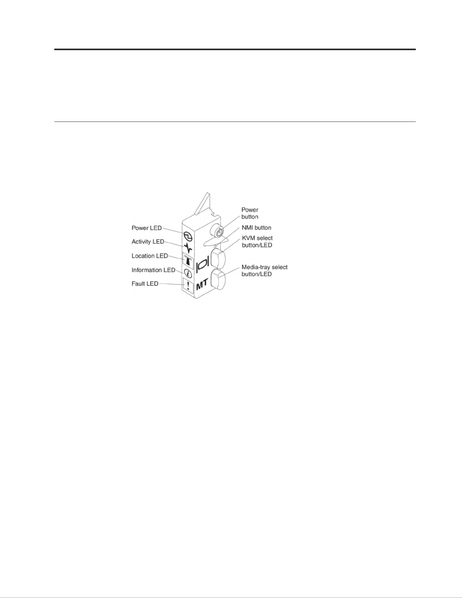
The following illustration identifies the buttons and information LEDs on the
blade-server control panel.
Power-on LED: This green LED indicates the power status of the blade server in
the following manner:
vFlashing rapidly: While the service processor in the blade server is initializing
and synchronizing with the management module, the power-on LED flashes
rapidly, and the power-control button on the blade server does not respond. This
process can take approximately two minutes after the blade server has been
installed. If the LED continues to flash rapidly, the blade server might not have
power permissions assigned to it through the Advanced Management Module,
the BladeCenter unit does not have enough power to turn on the blade server,
or the service processor (IMM) on the blade server is not communicating with
the Advanced Management Module.
vFlashing slowly: The blade server has power supplied and is ready to be turned
on.
vLit continuously: The blade server has power and is turned on.
Activity LED: When this green LED is lit, it indicates that there is activity on the
external storage device or network.
Location LED: The system administrator can remotely turn on this blue LED to aid
in visually locating the blade server. When this LED is lit, the location LED on the
BladeCenter unit is also lit. The location LED can be turned off through the
Advanced-Management-Module Web interface or through IBM
®Director Console.
For more information about the Advanced-Management-Module Web interface, see
http://www.ibm.com/systems/management/. For more information about IBM
®
Director, see the documentation on the IBM®Director CD that comes with the
© Copyright IBM Corp. 2012 15

server, or visit the IBM®Director Information Center at http://
publib.boulder.ibm.com/infocenter/director/v6r1x/index.jsp.
Information LED: When this amber LED is lit, it indicates that information about a
system event in the blade server has been placed in the Advanced-Management-
Module event log. The information LED can be turned off through the
Advanced-Management-Module CLI, SNMP, or Web interface or through IBM
®
Director Console. For more information about the Advanced-Management-Module
Web interface, see http://www.ibm.com/systems/management/. For more
information about IBM®Director, see the documentation on the IBM®Director CD
that comes with the server, or visit the IBM®Director Information Center at
http://publib.boulder.ibm.com/infocenter/director/v6r1x/index.jsp.
Fault LED: When this amber LED is lit, it indicates that a system error has
occurred in the blade server. The blade-error LED turns off only after the error is
corrected.
Power-control button: Press this button to turn on or turn off the blade server.
Note: The power-control button has effect only if local power control is enabled
for the blade server. Local power control is enabled and disabled through the
Advanced-Management-Module Web interface.
NMI button (recessed): The nonmaskable interrupt (NMI) dumps the partition.
Use this recessed button only as directed by IBM Support.
Note: You can also send an NMI event to the selected blade server remotely using
the AMM. For more information, see the BladeCenter Advanced Management Module
User's Guide.
Keyboard/video/mouse (KVM) select button: Press this button to associate the
shared BladeCenter unit keyboard port, video port, and mouse port with the blade
server. The LED on this button flashes while the request is being processed and
then is lit when the ownership of the keyboard, video, and mouse has been
transferred to the blade server. It can take approximately 20 seconds to switch the
keyboard, video, and mouse control to the blade server.
Using a keyboard that is directly attached to the Advanced-Management-Module,
you can press keyboard keys in the following sequence to switch KVM control
between blade servers instead of using the KVM select button:
NumLock NumLock Enterblade_server_number
blade_server_number is the two-digit number of the blade-server bay in which
the blade server is installed. A blade server that occupies more than one
blade-server bay is identified by the lowest bay number that it occupies.
If there is no response when you press the KVM select button, you can use the
Advanced-Management-Module Web interface to determine whether local control
has been disabled on the blade server. See http://www.ibm.com/systems/
management/ for more information.
Notes:
1. The operating system in the blade server must provide USB support for the
blade server to recognize and use the keyboard and mouse, even if the
keyboard and mouse have PS/2-style connectors.
16 BladeCenter HS22 Type 7870, 1936, and 1911: Installation and User's Guide
2. If you install a supported Microsoft Windows operating system on the blade
server while it is not the current owner of the keyboard, video, and mouse, a
delay of up to 1 minute occurs the first time that you switch the keyboard,
video, and mouse to the blade server. All subsequent switching takes place in
the normal KVM switching time frame (up to 20 seconds).
Media-tray select button: Press this button to associate the shared BladeCenter
unit media tray (removable-media drives) with the blade server. The LED on the
button flashes while the request is being processed and then is lit when the
ownership of the media tray has been transferred to the blade server. It can take
approximately 20 seconds for the operating system in the blade server to recognize
the media tray.
If there is no response when you press the media-tray select button, you can use
the Advanced-Management-Module Web interface to determine whether local
control has been disabled on the blade server.
Note: The operating system in the blade server must provide USB support for the
blade server to recognize and use the removable-media drives.
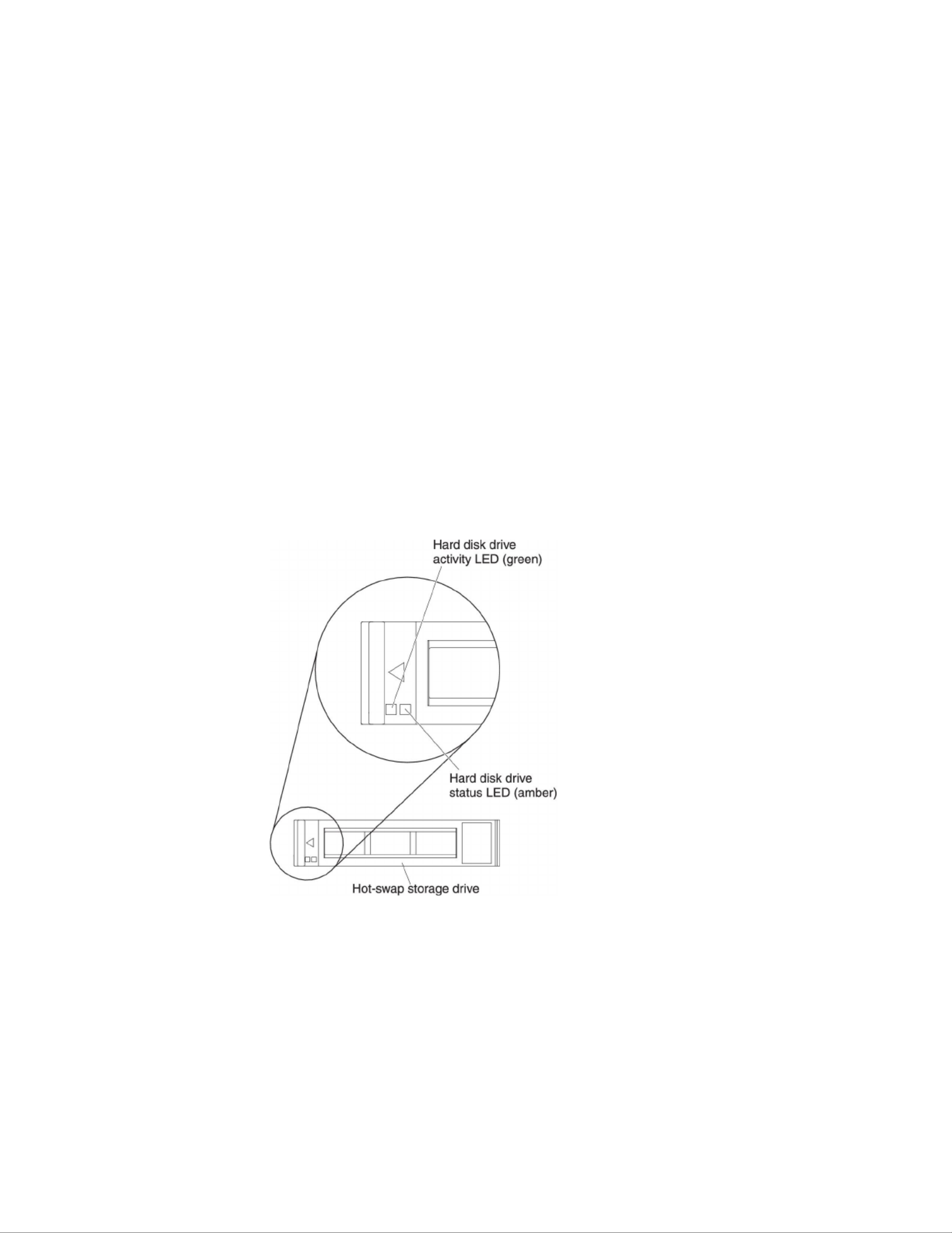
The following illustration identifies the information LEDs on the SAS hot-swap
hard disk drive.
Hard disk drive activity LED (green): When this green LED is lit, it indicates that
there is activity on the storage drive.
Hard disk drive status LED (amber): When this amber LED is lit, it indicates that
an error has occurred with the storage drive. The LED turns off only after the error
is corrected.
Chapter 2. Power, controls, and indicators 17

Turning on the blade server
Use this information to turn on the blade server.
After you connect the blade server to power through the BladeCenter unit, the
blade server can start in any of the following ways:
vYou can press the power-control button on the front of the blade server (see
“Blade server controls and LEDs” on page 15) to start the blade server.
Notes:
1. Wait until the power-on LED on the blade server flashes slowly before you
press the power-control button. While the service processor in the blade
server is initializing and synchronizing with the management module, the
power-on LED flashes rapidly, and the power-control button on the blade
server does not respond. This process can take approximately two minutes
after the blade server has been installed.
2. While the blade server is starting, the power-on LED on the front of the
blade server is lit and does not flash. See “Blade server controls and LEDs”
on page 15 for the power-on LED states.
vIf a power failure occurs, the BladeCenter unit and the blade server can be
configured to start automatically when power is restored through the Advanced
Management Module.
vYou can turn on the blade server remotely by using the management module.
vIf the blade server is connected to power (the power-on LED is flashing slowly),
the blade server is communicating with the management module, the operating
system supports the Wake on LAN feature, and the Wake on LAN feature has
not been disabled through the management module, the Wake on LAN feature
can turn on the blade server.
Turning off the blade server
Use this information to turn off the blade server.
When you turn off the blade server, it is still connected to power through the
BladeCenter unit. The blade server can respond to requests from the service
processor, such as a remote request to turn on the blade server. To remove all
power from the blade server, you must remove it from the BladeCenter unit. Shut
down the operating system before you turn off the blade server. See the
operating-system documentation for information about shutting down the
operating system.
The blade server can be turned off in any of the following ways:
vYou can press the power-control button on the blade server (see “Blade server
controls and LEDs” on page 15). This starts an orderly shutdown of the
operating system, if this feature is supported by the operating system.
vIf the operating system stops functioning, you can press and hold the
power-control button for more than 4 seconds to turn off the blade server.
vThe management module can turn off the blade server through the
Advanced-Management-Module Web interface. For additional information, see
the IBM BladeCenter Management Module User’s Guide or go to
http://www-03.ibm.com/systems/management/ for more information.
18 BladeCenter HS22 Type 7870, 1936, and 1911: Installation and User's Guide
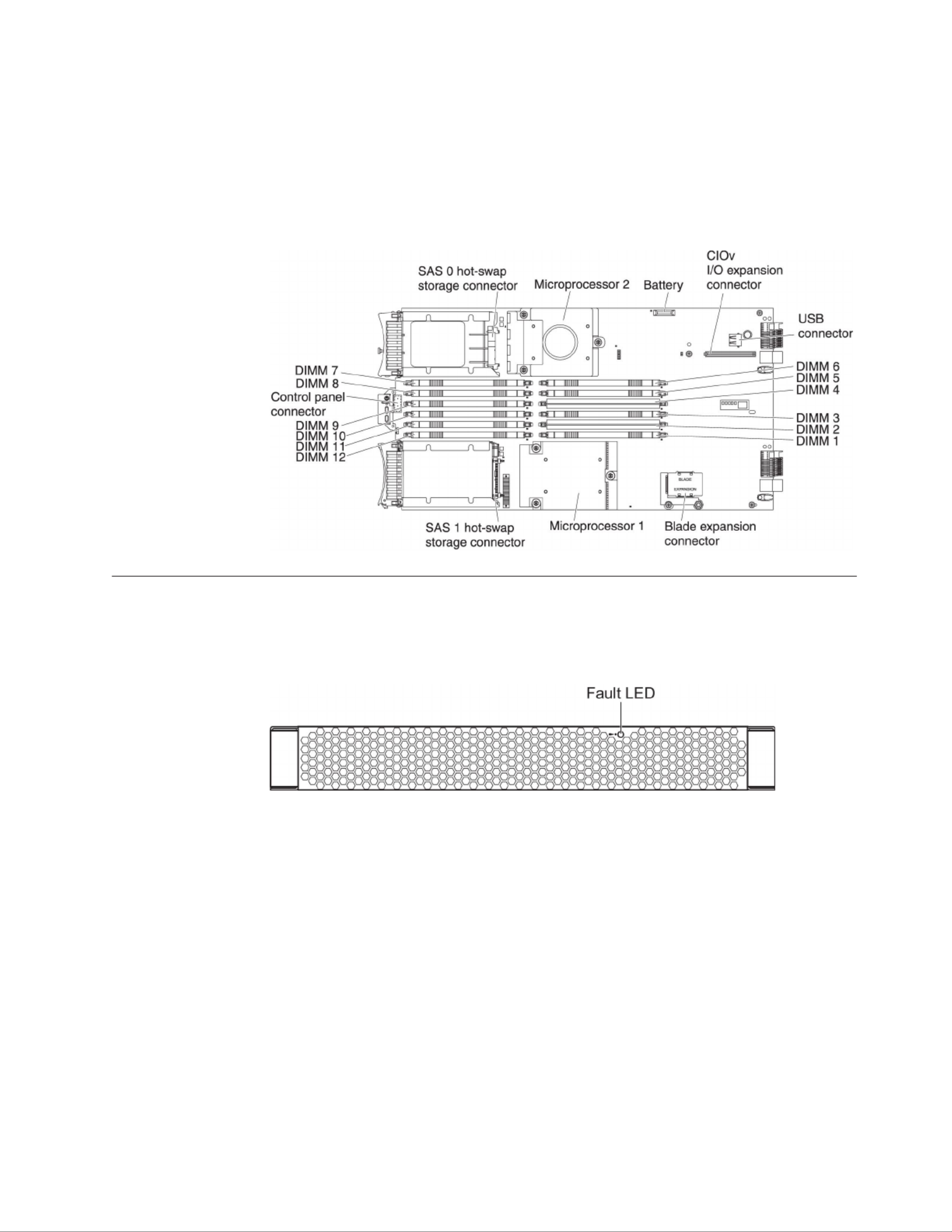
Blade server connectors
Use this information to locate blade server system-board components and
connectors for optional devices.
The following illustration shows the system-board components, including
connectors for user-installable optional devices, in the blade server.
BladeCenter GPU expansion unit LED
The following illustration identifies the fault LED on the front of the BladeCenter
GPU expansion (BGE) unit.
Fault LED: When this amber LED is lit, it indicates that an error has occurred in
the expansion blade. The expansion blade error LED turns off only after the error
is corrected.
If an error occurs in the expansion blade, the fault LED on the blade device on
which the expansion blade is installed is also lit. Additional information about the
error is provided by the light-path LEDs in the expansion blade (see the Problem
Determination and Service Guide that comes with your server for more information).
Chapter 2. Power, controls, and indicators 19

20 BladeCenter HS22 Type 7870, 1936, and 1911: Installation and User's Guide

Chapter 3. Installing options
Use this information for instructions about installing optional hardware devices in
the blade server. Some option-removal instructions are provided in case you have
to remove one option to install another.
Installation guidelines
Use these guidelines before you install the blade server or optional devices.
Before you install optional devices, read the following information:
vBefore you begin, read “Safety” on page v and “Handling static-sensitive
devices” on page 22. This information will help you work safely.
vWhen you install your new blade server, take the opportunity to download and
apply the most recent firmware updates. This step will help to ensure that any
known issues are addressed and that your blade server is ready to function at
maximum levels of performance.
Note: Changes are made periodically to the IBM Web site. The actual procedure
might vary slightly from what is described in this document.
To download firmware updates for your blade server, complete the following
steps:
1. Go to http://www.ibm.com/systems/support/.
2. Under , click .Product support BladeCenter
3. Under , click .Popular links Software and device drivers
4. Click to display the matrix of downloadable files for theBladeCenter HS22
blade server.
vObserve good housekeeping in the area where you are working. Place removed
covers and other parts in a safe place.
vBack up all important data before you make changes to disk drives.
vBefore you remove a blade server from the BladeCenter unit, you must shut
down the operating system and turn off the blade server. You do not have to
shut down the BladeCenter unit itself.
vBlue on a component indicates touch points, where you can grip the component
to remove it from or install it in the blade server, open or close a latch, and so
on.
vOrange on a component or an orange label on or near a component indicates
that the component can be hot-swapped, which means that if the server and
operating system support hot-swap capability, you can remove or install the
component while the server is running. (Orange can also indicate touch points
on hot-swap components.) See the instructions for removing or installing a
specific hot-swap component for any additional procedures that you might have
to perform before you remove or install the component.
vFor a list of supported optional devices for the blade server, see
http://www.ibm.com/servers/eserver/serverproven/compat/us/.
© Copyright IBM Corp. 2012 21

System reliability guidelines
Use this information to make sure that the blade server meets the proper cooling
and reliability guidelines.
To help make sure that proper cooling and system reliability requirements are met,
review the following guidelines:
vTo ensure proper cooling, do not operate the BladeCenter unit without a blade
server, expansion unit, or blade filler installed in each blade-server bay. See the
documentation for your BladeCenter unit for additional information.
vEach microprocessor socket always contains either a microprocessor dust cover
and heat sink filler or a microprocessor and heat sink. If the blade server has
only one microprocessor, it must be installed in microprocessor socket 1.
vEach DIMM socket always contains a memory module or filler.
vEach hot-swap SAS bay contains a SAS storage drive or filler.
vMake sure that the ventilation holes on the blade server are not blocked.
vThe blade server battery must be operational. If the battery becomes defective,
replace it immediately. For instructions, see the Problem Determination and Service
Guide.
Handling static-sensitive devices
Use this information to observe the static-sensitive device requirements.
Attention: Static electricity can damage the blade server and other electronic
devices. To avoid damage, keep static-sensitive devices in their static-protective
packages until you are ready to install them.
To reduce the possibility of damage from electrostatic discharge, observe the
following precautions:
vWhen you work on a BladeCenter unit that has an electrostatic discharge (ESD)
connector, use a wrist strap, especially when you handle modules, optional
devices, or blade servers. To work correctly, the wrist strap must have a good
contact at both ends (touching your skin at one end and firmly connected to the
ESD connector on the front or back of the BladeCenter unit).
vLimit your movement. Movement can cause static electricity to build up around
you.
vHandle the device carefully, holding it by its edges or its frame.
vDo not touch solder joints, pins, or exposed circuitry.
vDo not leave the device where others can handle and damage it.
vWhile the device is still in its static-protective package, touch it to an unpainted
metal part of the BladeCenter unit or any metal surface on any otherunpainted
grounded rack component in the rack in which you are installing the device for
at least 2 seconds. This drains static electricity from the package and from your
body.
vRemove the device from its package and install it directly into the blade server
without setting down the device. If it is necessary to set down the device, put it
back into its static-protective package. Do not place the device on the blade
server cover or on a metal surface.
vTake additional care when you handle devices during cold weather. Heating
reduces indoor humidity and increases static electricity.
22 BladeCenter HS22 Type 7870, 1936, and 1911: Installation and User's Guide

Removing the blade server from the BladeCenter unit
Use these instructions to remove the blade server from the BladeCenter unit.
The following illustration shows how to remove a single-width type of blade
server or blade filler from a Type 8677 BladeCenter unit. The appearance of your
BladeCenter unit might be different; see the documentation for your BladeCenter
unit for additional information.
Attention:
vTo maintain proper system cooling, do not operate the BladeCenter unit without
a blade server, expansion unit, or filler module installed in each blade server
bay.
vWhen you remove the blade server, note the blade-server bay number.
Reinstalling a blade server into a different blade server bay from the one it was
removed from can have unintended consequences. Some configuration
information and update options are established according to blade-server bay
number; if you reinstall the blade server into a different bay, you might have to
reconfigure the blade server.
To remove the blade server, complete the following steps:
1. If the blade server is operating, shut down the operating system (see the
documentation for your operating system for more information).
2. If the server is still on, press the power-control button for four seconds to turn
off the blade server (see “Turning off the blade server” on page 18 for more
information).
Attention: Wait at least 30 seconds, until the storage devices stops spinning,
before you proceed to the next step.
3. Open the two release handles as shown in the illustration. The blade server
moves out of the blade server bay approximately 0.6 cm (0.25 inch).
4. Pull the blade server out of the bay.
Attention: Two people are required to remove a Type 1911 blade server out of
the bay.
Statement 4: (for Type 1911)
Chapter 3. Installing options 23
≥18 kg (39.7 lb)
CAUTION:
Use safe practices when lifting.
5. Place either a blade filler or another blade server in the blade server bay within
1 minute.
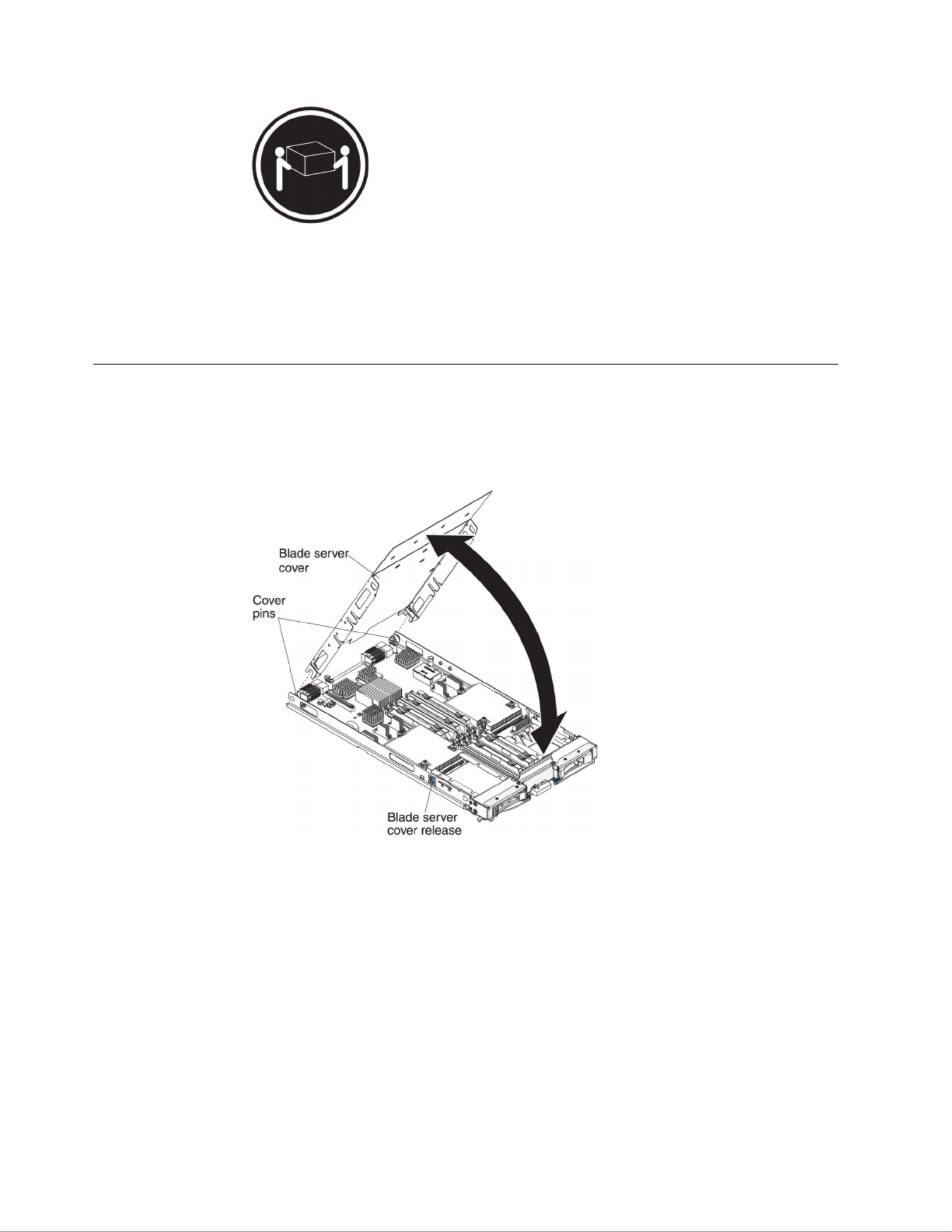
Removing the blade server cover
Use these instructions to open the blade server cover.
The following illustration shows how to open the cover on the blade server.
To open the blade server cover, complete the following steps.
1. Before you begin, read “Safety” on page v and “Installation guidelines” on
page 21.
2. If the blade server is installed in a BladeCenter unit, remove it (see “Removing
the blade server from the BladeCenter unit” on page 23 for instructions).
3. Carefully lay the blade server on a flat, static-protective surface, with the cover
side up.
4. Press the blade server cover release on each side of the blade server or
expansion unit and lift the cover open, as shown in the illustration.
5. Lay the cover flat, or lift it from the blade server and store for future use.
Statement 21
24 BladeCenter HS22 Type 7870, 1936, and 1911: Installation and User's Guide

CAUTION:
Hazardous energy is present when the blade server is connected to the power
source. Always replace the blade cover before installing the blade server.
Installing an optional expansion unit
Use these instructions to install an optional expansion unit.
Attention: If a horizontal combination-form-factor (CFFh) expansion card is
installed on the blade server system board, you cannot install an optional
expansion unit.
Notes:
1. All devices should be installed in an expansion unit before attaching it to the
blade server.
2. After you install one or more expansion units on your blade server, the
combined blade server and expansion units together occupy adjacent blade
bays in the BladeCenter unit. Enough power modules must be installed in the
BladeCenter unit to power the blade bays in which you install the blade server
and expansion units.
3. The following illustration shows an optional expansion unit in a blade server.
4. The illustrations in this document might differ slightly from your hardware.
To install an optional expansion unit, complete the following steps.
1. Before you begin, read “Safety” on page v and “Installation guidelines” on
page 21. To determine the type and number of expansion units that can be
installed on your blade server, see http://www.ibm.com/servers/eserver/
serverproven/compat/us/.
2. If the blade server is installed in a BladeCenter unit, remove it (see
“Removing the blade server from the BladeCenter unit” on page 23 for
instructions).
3. Remove the cover from the blade server or the expansion unit (see “Removing
the blade server cover” on page 24.
Chapter 3. Installing options 25

4. Locate the blade expansion connector on the blade server system board or the
expansion unit and remove the cover if one is installed (see “Blade server
connectors” on page 19).
5. Touch the static-protective package that contains the optional expansion unit
to any metal surface on the BladeCenter unit or any metalunpainted unpainted
surface on any other grounded rack component; then, remove the optional
expansion unit from the package.
6. Orient the optional expansion unit as shown in the illustration.
7. Lower the expansion unit so that the slots at the rear slide down onto the
cover pins at the rear of the blade server; then, pivot the expansion unit down
onto the blade server.
8. If the expansion unit has an extraction device (such as a thumbscrew or a
lever), use it to fully engage the expansion unit on the blade server; otherwise,
press the expansion unit firmly into the closed position until it clicks into
place. To install an optional GPU adapter into a GPU expansion unit, see
“Installing a GPU adapter in the BladeCenter GPU expansion unit” on page
34. To install an option into another type of expansion unit, refer to the
documentation provided with the expansion unit.
9. If additional expansion units are being installed, repeat steps 4 through 8 for
each expansion blade; otherwise continue with step 11.
10. Follow the instructions provided with the expansion unit to install an option
in the expansion unit.
11. If you have other devices to install or remove, do so now; otherwise, go to
“Completing the installation” on page 54.
Removing an optional expansion unit
Use these instructions to remove the optional expansion unit from the blade server.
Note: For instruction on removing an expansion unit from the the IBM WebSphere
DataPower Integration Blade XI50B Type 4195 appliance, see the Installation and
User's Guide that came with the blade appliance.
To remove an optional expansion unit, complete the following steps:
1. Before you begin, read “Safety” on page v and “Installation guidelines” on
page 21.
26 BladeCenter HS22 Type 7870, 1936, and 1911: Installation and User's Guide
2. If the blade server is installed in a BladeCenter unit, remove it (see “Removing
the blade server from the BladeCenter unit” on page 23 for instructions).
3. Carefully lay the blade server on a flat, static-protective surface, with the cover
side up.
4. Remove the blade server cover, if one is installed (see “Removing the blade
server cover” on page 24 for instructions).
5. Remove the expansion unit:
a. If the expansion unit has an extraction device, use the extraction device to
disengage the expansion unit from the blade server. These extraction
devices can be of several types, including thumbscrews or levers. See the
instructions provided with the expansion unit for detailed instructions for
removing the expansion unit.
b. If the expansion unit does not have an extraction device, press the blade
server cover release on each side of the blade server and lift the expansion
unit from the blade server.
c. Rotate the expansion unit open; then, lift the expansion unit from the blade
server.
6. If you are instructed to return the expansion unit, remove from it any options
that you have installed; then, follow all packaging instructions, and use any
packaging materials for shipping that are supplied to you.
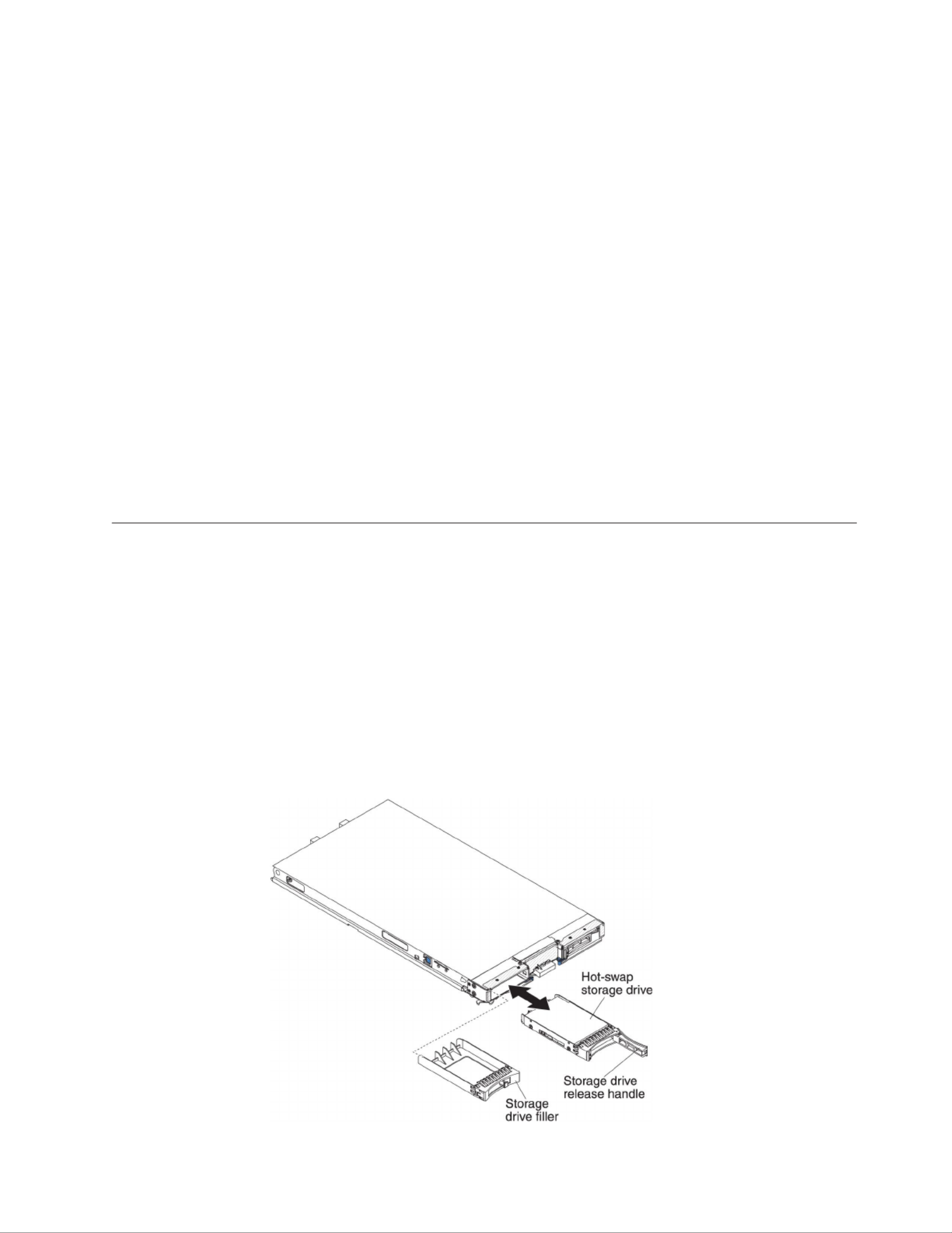
Installing a hot-swap storage drive
Use these instructions to install a hot-swap storage drive into the blade server.
The blade server has two SAS storage bays for installing hot-swap storage drives,
such as a hot-swap SAS hard disk drive. One storage drive might already be
installed in the blade server in storage bay 0. If the blade server is equipped with
one storage drive, you can install an additional drive in storage bay 1. The blade
server supports using RAID 0 or RAID 1 when two storage drives of the same
interface type are installed. See “Configuring a RAID array” on page 67 for
information about SAS RAID configuration.
To install a hot-swap storage drive or drive filler, complete the following steps.
Chapter 3. Installing options 27

1. Before you begin, read “Safety” on page v and “Installation guidelines” on
page 21.
2. Identify the SAS storage bay (storage bay 0 or storage bay 1) in which the
hot-swap storage drive will be installed (see “Blade server connectors” on page
19).
3. If a storage-bay filler is installed, remove it from the blade server by pulling the
release lever and sliding the filler away from the blade server (see “Removing a
hot-swap storage drive”).
4. Touch the static-protective package that contains the hot-swap storage drive to
any metal surface on the BladeCenter unit or any metalunpainted unpainted
surface on any other grounded rack component; then, remove the hard disk
drive from the package.
5. Open the release lever on the hot-swap storage drive and slide the drive into
the storage bay until it is firmly seated in the connector.
6. Lock the hot-swap storage drive into place by closing the release lever.
If you have other devices to install or remove, do so now; otherwise, go to
“Completing the installation” on page 54.
Removing a hot-swap storage drive
Use this information to remove a hot-swap storage drive.
The blade server has two SAS hot-swap storage bays for installing or removing
hot-swap storage devices, such as a SAS storage drive. To remove a hot-swap hard
disk drive or drive filler, complete the following steps.
1. Before you begin, read “Safety” on page v and “Installation guidelines” on
page 21.
2. Press the release latch (orange) on the storage drive to release the drive handle.
3. Pull the release handle to remove the drive from the storage bay.
28 BladeCenter HS22 Type 7870, 1936, and 1911: Installation and User's Guide
Installing a memory module
Use these instructions to install memory modules in the blade server.
The blade server has a total of twelve direct inline memory module (DIMM) slots.
The blade server supports very low profile (VLP) DDR3 DIMMs with error code
correction (ECC) in 1 GB, 2 GB, 4 GB, 8 GB, and 16 GB capacities. For a current list
of supported DIMMs for the blade server, see http://www.ibm.com/servers/
eserver/serverproven/compat/us/.
After you install or remove a DIMM, you must change and save the new
configuration information by using the Setup utility. When you turn on the blade
server, a message indicates that the memory configuration has changed. Start the
Setup utility and select (see “Setup utility menu” on page 60 forSave Settings
more information) to save changes.
The memory is accessed internally through the system using six channels. Each
channel contains two DIMM connectors. The following table lists each channel and
which DIMM connectors belong to the channel.
Table 2. Memory channel configuration
Memory channel DIMM connector
Channel 0 DIMM connector 1 and 2
Channel 1 DIMM connector 5 and 6
Channel 2 DIMM connector 3 and 4
Channel 3 DIMM connector 7 and 8
Channel 4 DIMM connector 11 and 12
Channel 5 DIMM connector 9 and 10
Depending on the memory mode that is set in the Setup utility, the blade server
can support a minimum of 1 GB and a maximum of 48 GB of system memory on
the system board in a blade server with one processor. If two microprocessors are
installed, the blade server can support a minimum of 2 GB and a maximum of 96
GB of system memory. There are two different memory modes:
vIndependent channel mode: Independent channel mode gives a maximum of 96
GB of usable memory with one CPU installed, and 192 GB of usable memory
with 2 CPUs installed (using 16 GB DIMMs). The DIMMs can be installed
without matching sizes. See the table below for the memory installation order.
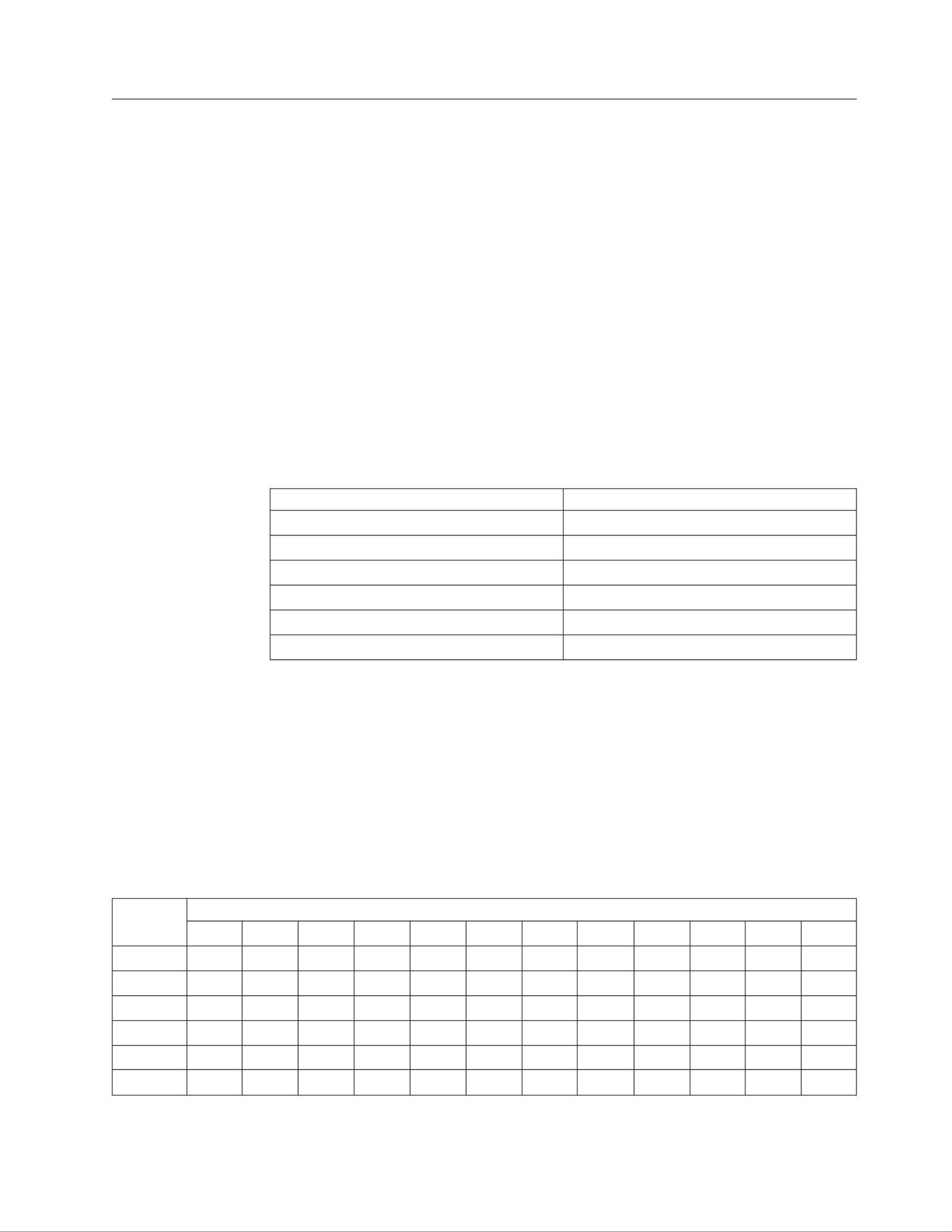
Table 3. System memory configuration for independent channel mode (1 microprocessor)
Installed
memory
DIMM socket
1 2 3 4 5 6 7 8 9 10 11 12
1 DIMM X
2 DIMMs X X
3 DIMMs X X X
4 DIMMs X X X X
5 DIMMs X X X X X
6 DIMMs X X X X X X
Chapter 3. Installing options 29

Table 4. System memory configuration for independent channel mode (2 microprocessors)
Installed
memory
DIMM socket
1 2 3 4 5 6 7 8 9 10 11 12
2 DIMMs X X
3 DIMMs X X X
4 DIMMs X X X X
5 DIMMs X X X X X
6 DIMMs X X X X X X
7 DIMMs X X X X X X X
8 DIMMs X X X X X X X X
9 DIMMs X X X X X X X X X
10 DIMMs X X X X X X X X X X
11 DIMMs X X X X X X X X X X X
12 DIMMs X X X X X X X X X X X X
vMirrored channel mode: In mirrored channel mode, channels 2 and 5 are
unused. The memory contents on channel 0 are duplicated in channel 1, and the
memory contents of channel 3 are duplicated in channel 4. The effective memory
available to the system is only half of that installed. The maximum available
memory (with 16 GB DIMMs) is 32 GB for a single CPU system and 64 GB for a
dual CPU system.
Important: The memory configuration of channel 0 must match that of channel
1, and the memory configuration of channel 3 must match that of channel 4. For
example, if a 4 GB Dual Rank DIMM is installed into the DIMM2 connector,
then a 4 GB Dual Rank DIMM must also be installed into the DIMM6 connector.
Table 2 on page 29 lists each channel and which DIMM connectors belong to the
channel.
The following table shows the order that memory DIMMs are installed to use a
mirrored channel mode.
Table 5. System memory configuration for mirrored channel mode (1 microprocessor)
Installed
memory
DIMM socket
1 2 3 4 5 6 7 8 9 10 11 12
2 DIMMs X X
4 DIMMs X X X X
Table 6. System memory configuration for mirrored channel mode (2 microprocessors)
Installed
memory
DIMM socket
1 2 3 4 5 6 7 8 9 10 11 12
4 DIMMs X X X X
6 DIMMs X X X X X X
8 DIMMs X X X X X X X X
vSpare channel mode: In spare channel mode, channel 2 is the spare of the active
channels 0 and 1. The spare channel is not available as active memory. The
maximum memory available (with 16 GB DIMMs) is 64 GB in a single CPU
system and 128 GB in a dual CPU system. All three channels must have
30 BladeCenter HS22 Type 7870, 1936, and 1911: Installation and User's Guide

identical population with regards to size and organization. DIMMs within a
channel do not have to be identical. The population ordering for spare channel
mode is shown in the table below.
Note: Spare channel mode is only supported if the blade server has an Intel
Xeon 5600 series microprocessor. Use the Setup utility to view the system
summary and verify the type of microprocessor installed in your blade server
(see “Using the Setup utility” on page 60).
The following table shows the order that memory DIMMs are installed to use
spare channel mode.
Table 7. System memory configuration for spare channel mode (1 microprocessor)
Installed
memory
DIMM socket
1 2 3 4 5 6 7 8 9 10 11 12
3 DIMMs X X X
6 DIMMs X X X X X X
Table 8. System memory configuration for spare channel mode (2 microprocessors)
Installed
memory
DIMM socket
1 2 3 4 5 6 7 8 9 10 11 12
6 DIMMs X X X X X X
9 DIMMs X X X X X X X X X
12 DIMMs X X X X X X X X X X X X
Chapter 3. Installing options 31

To install a DIMM, complete the following steps:
1. Before you begin, read “Safety” on page v and “Installation guidelines” on
page 21.
2. Read the documentation that comes with the DIMMs.
3. If the blade server is installed in a BladeCenter unit, remove it (see
“Removing the blade server from the BladeCenter unit” on page 23 for
instructions).
4. Carefully lay the blade server on a flat, static-protective surface.
5. Open the blade server cover (see “Removing the blade server cover” on page
24 for instructions).
6. If an expansion unit is installed and you are installing DIMMs on the system
board, remove the expansion unit (see “Removing an optional expansion unit”
on page 26).
7. Locate the DIMM connectors (see “Blade server connectors” on page 19).
Determine which DIMM connector you will be installing memory into.
8. If a DIMM filler or another memory module is already installed in the DIMM
connector, remove it (see “Removing a memory module” on page 33).
Note: A DIMM or DIMM filler must occupy each DIMM socket before the
blade server is turned on.
9. If you are installing a DIMM in DIMM connector seven through twelve, use
your fingers to lift the DIMM access door.
10. Touch the static-protective package that contains the DIMM to any unpainted
metal surface on the BladeCenter unit or any metal surface on anyunpainted
other grounded rack component in the rack in which you are installing the
DIMM for at least two seconds; then, remove the DIMM from its package.
11. To install the DIMMs, repeat the following steps for each DIMM that you
install:
32 BladeCenter HS22 Type 7870, 1936, and 1911: Installation and User's Guide
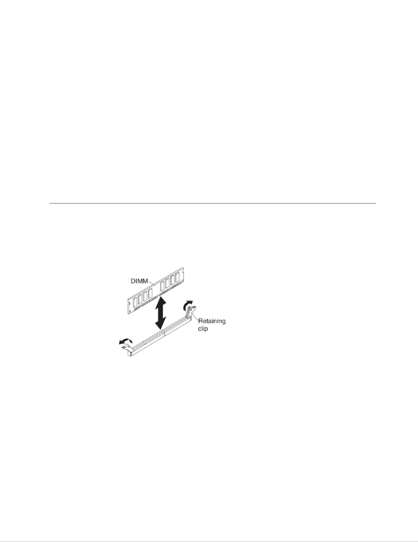
a. Make sure that the retaining clips are in the open position, away from the
center of the DIMM connector.
b. Turn the DIMM so that the DIMM keys align correctly with the DIMM
connector on the system board.
Attention: To avoid breaking the retaining clips or damaging the DIMM
connectors, handle the clips gently.
c. Press the DIMM into the DIMM connector. The retaining clips will lock the
DIMM into the connector.
d. Make sure that the small tabs on the retaining clips are in the notches on
the DIMM. If there is a gap between the DIMM and the retaining clips, the
DIMM has not been correctly installed. Press the DIMM firmly into the
connector, and then press the retaining clips toward the DIMM until the
tabs are fully seated. When the DIMM is correctly installed, the retaining
clips are parallel to the sides of the DIMM.
12. If the DIMM access door is open, use your fingers to close it.
13. If you have other devices to install or remove, do so now; otherwise, go to
“Completing the installation” on page 54.
Removing a memory module
Use this information to remove a memory module from the blade server.
The following illustration shows how to remove a DIMM from the blade server.
This information also applies to removing a DIMM filler.
To remove a DIMM, complete the following steps.
1. Before you begin, read “Safety” on page v and “Installation guidelines” on
page 21.
2. If the blade server is installed in a BladeCenter unit, remove it (see “Removing
the blade server from the BladeCenter unit” on page 23).
3. Remove the blade server cover (see “Removing the blade server cover” on page
24).
4. If an optional expansion unit is installed, remove the expansion unit (see
“Removing an optional expansion unit” on page 26).
5. Locate the DIMM connectors (see “Blade server connectors” on page 19).
Determine which DIMM you want to remove from the blade server.
Attention: To avoid breaking the retaining clips or damaging the DIMM
connectors, handle the clips gently.
Chapter 3. Installing options 33

6. Move the retaining clips on the ends of the DIMM connector to the open
position by pressing the retaining clips away from the center of the DIMM
connector.
Note: To access DIMM connector seven through twelve, use your fingers to lift
the DIMM access door.
7. Using your fingers, pull the DIMM out of the connector.
8. Install a DIMM or DIMM filler in each empty DIMM connector (see “Installing
a memory module” on page 29).
Note: A DIMM or DIMM filler must occupy each DIMM socket before the
blade server is turned on.
Installing a GPU adapter in the BladeCenter GPU expansion unit
Use these instructions to install a GPU adapter in the BladeCenter GPU expansion
unit installed on a blade server.
To install a GPU adapter in the BladeCenter GPU expansion unit, complete the
following steps:
1. Before you begin, read “Safety” on page v and “Installation guidelines” on
page 21.
2. If the blade server is installed in a BladeCenter unit, remove it (see
“Removing the blade server from the BladeCenter unit” on page 23 for
instructions).
3. If the expansion unit is installed on a blade server or another expansion unit,
remove it (see “Removing an optional expansion unit” on page 26 for
instructions).
4. Remove the blade server cover (see “Removing the blade server cover” on
page 24 for instructions).
5. If an expansion unit is installed over the expansion unit you want to install
the adapter in, remove that expansion unit (see “Removing an optional
expansion unit” on page 26 for instructions).
6. If you have not already done so, touch the static-protective package that
contains the GPU adapter to any metal surface of the BladeCenterunpainted
unit or any metal surface on any other grounded rack-componentunpainted
for at least 2 seconds.
7. Remove the GPU adapter from its static-protective package.
8. Connect the GPU adapter to the PCI connector in the expansion-unit riser
assembly, as shown in the following illustration.
34 BladeCenter HS22 Type 7870, 1936, and 1911: Installation and User's Guide
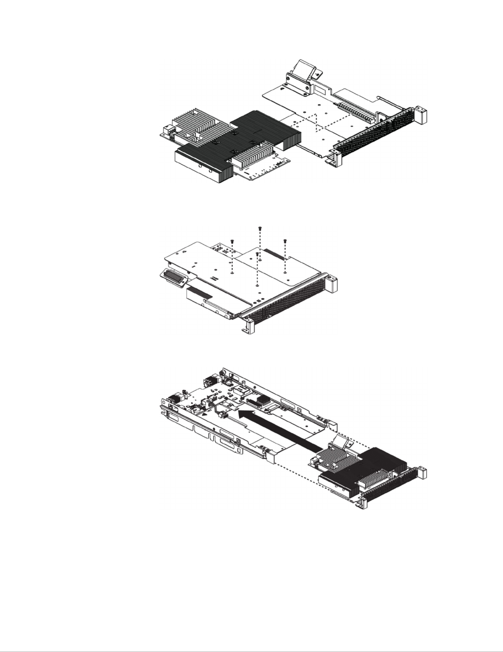
9. Carefully turn over the expansion-unit riser assembly, and use a Phillips
screwdriver to install the four non-captive retaining screws, as shown in the
following illustration.
10. Turn over the expansion-unit riser assembly and install the riser assembly into
the expansion unit system board, as shown in the following illustration.
11. Carefully reposition the expansion-unit riser assembly, aligning it with the
expansion-unit system-board-assembly rails.
12. Firmly slide the assemblies together until the tray-release button securely
locks the panels.
13. Connect the auxiliary power cable (A), as shown in the following illustration.
Chapter 3. Installing options 35

14. Connect the cable to the expansion-unit system board. Replace the retention
bracket and tighten the screws (B), as shown in the illustration above.
If you have other devices to install or remove, do so now; otherwise, go to
“Completing the installation” on page 54.
Removing a GPU adapter from the BladeCenter GPU expansion unit
Use this information to remove a GPU adapter from the BladeCenter GPU
expansion unit.
Notes:
1. The following illustration shows how to remove a GPU adapter from the
BladeCenter GPU expansion unit.
2. The illustrations in this document might differ slightly from your hardware.
To remove a GPU adapter from the BladeCenter GPU expansion unit, complete the
following steps:
1. Before you begin, read “Safety” on page v and “Installation guidelines” on
page 21.
2. If the blade server is installed in a BladeCenter unit, remove it (see “Removing
the blade server from the BladeCenter unit” on page 23 for instructions).
3. Remove the blade server cover (see “Removing the blade server cover” on page
24 for instructions).
4. If an expansion blade is installed on the expansion blade containing the adapter
you want to remove, remove it (see “Removing an optional expansion unit” on
page 26.)
5. Remove the expansion-blade riser assembly from the BladeCenter GPU
expansion blade:
a. Disconnect the auxiliary power cable (A) from the GPU adapter, as shown
in the following illustration.
36 BladeCenter HS22 Type 7870, 1936, and 1911: Installation and User's Guide

b. Loosen the screws and remove the retention bracket, then disconnect the
cable from the expansion-unit system board (B).
c. Locate the tray-release button on the bottom of the expansion unit.
d. Press in and hold the tray-release button; then, pull the expansion-unit riser
assembly out of the expansion-unit system board.
Chapter 3. Installing options 37
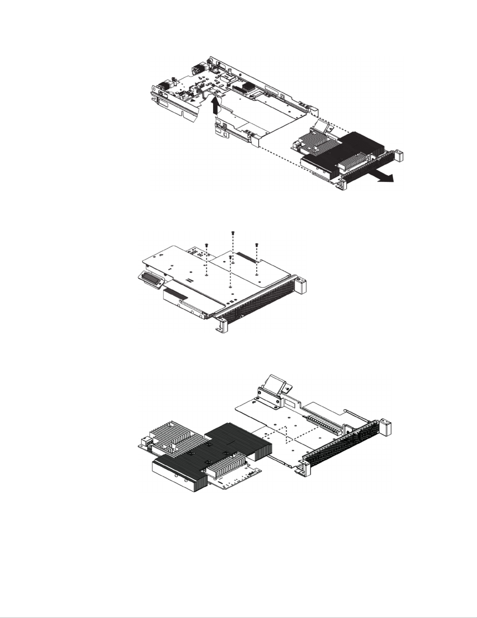
6. Carefully turn over the expansion-unit riser assembly, and use a Phillips
screwdriver to remove the four non-captive retaining screws, as shown in the
following illustration. Store the screws in a safe location.
7. Carefully turn the expansion-unit riser assembly back over. Unplug the GPU
adapter from the PCI connector in the riser assembly and lift it out of the riser
assembly.
8. If you are instructed to return the GPU adapter, follow all packaging
instructions, and use any packaging materials for shipping that are supplied to
you.
38 BladeCenter HS22 Type 7870, 1936, and 1911: Installation and User's Guide
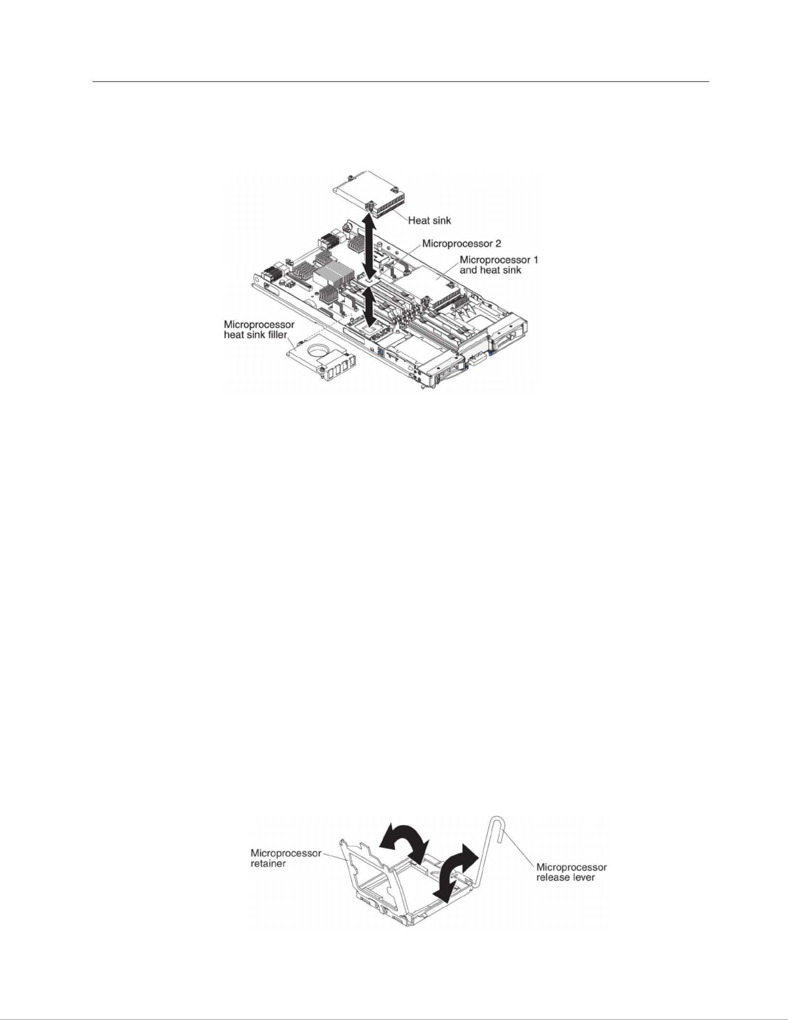
Installing a microprocessor and heat sink
The following illustration shows how to install a microprocessor and heat sink in
the blade server.
Attention:
1. Do not use any tools or sharp objects to lift the locking lever on the
microprocessor socket. Doing so might result in permanent damage to the
system board.
2. Do not touch the contacts in the microprocessor socket. Touching these contacts
might result in permanent damage to the system board.
To install a microprocessor and heat sink, complete the following steps:
1. Before you begin, read “Safety” on page v and “Installation guidelines” on
page 21.
2. Shut down the operating system, turn off the blade server, and remove the
blade server from the BladeCenter unit. See “Removing the blade server from
the BladeCenter unit” on page 23 for instructions.
3. Carefully lay the blade server on a flat, static-protective surface.
4. Open the blade server cover (see “Removing the blade server cover” on page
24 for instructions).
5. If you are installing a microprocessor in the blade server and an MPE unit or
expansion unit is attached to the blade server, remove the device (see
“Removing an optional expansion unit” on page 26).
6. Locate microprocessor socket 2 (see “Blade server connectors” on page 19).
7. Loosen the four captive screws that secure the heat-sink filler and then
remove the filler from the microprocessor socket.
8. Open the microprocessor socket release lever and retainer.
Chapter 3. Installing options 39
Produktspecifikationer
| Varumärke: | Lenovo |
| Kategori: | Server |
| Modell: | BladeCenter HS22 |
Behöver du hjälp?
Om du behöver hjälp med Lenovo BladeCenter HS22 ställ en fråga nedan och andra användare kommer att svara dig
Server Lenovo Manualer

4 September 2024
2 September 2024
2 September 2024
29 Augusti 2024
26 Augusti 2024
25 Augusti 2024
25 Augusti 2024
24 Augusti 2024
23 Augusti 2024
23 Augusti 2024
Server Manualer
- Server Sony
- Server HP
- Server Toshiba
- Server Abus
- Server Acer
- Server Allnet
- Server Apc
- Server Acti
- Server Hikvision
- Server Asus
- Server SilverStone
- Server Megasat
- Server Maxdata
- Server Black Box
- Server Tripp Lite
- Server Axis
- Server Gigabyte
- Server Nec
- Server Technics
- Server Cisco
- Server AVerMedia
- Server Matrox
- Server Flir
- Server Fujitsu
- Server Digitus
- Server Kathrein
- Server Asrock
- Server Linksys
- Server Buffalo
- Server Supermicro
- Server GeoVision
- Server Netgear
- Server QNAP
- Server LaCie
- Server Dell
- Server Valcom
- Server Asustor
- Server Planet
- Server ZyXEL
- Server Western Digital
- Server Intel
- Server Fantec
- Server MSI
- Server D-Link
- Server Freecom
- Server Eaton
- Server Seagate
- Server Iomega
- Server Synology
- Server Elac
- Server Blackmagic Design
- Server ATen
- Server Veritas
- Server Digi
- Server Revox
- Server Conceptronic
- Server Gefen
- Server Luxman
- Server Quantum
- Server Areca
- Server SEH
- Server Ibm
- Server Provision ISR
- Server Sonnet
- Server Monacor
- Server TAIDEN
- Server Moxa
- Server Smart-AVI
- Server StarTech.com
- Server SIIG
- Server Advantech
- Server Extron
- Server KanexPro
- Server Avocent
- Server Intellinet
- Server Teradek
- Server Vimar
- Server Silex
- Server Kramer
- Server Hanwha
- Server In Win
- Server Lindy
- Server Ernitec
- Server Sun
- Server Atlona
- Server MvixUSA
- Server Dual Bay
- Server Raidsonic
- Server EMC
- Server AMX
- Server Rocstor
- Server Infortrend
- Server Opengear
- Server G-Technology
- Server EXSYS
- Server Raritan
- Server Chenbro Micom
- Server Middle Atlantic
- Server Mr. Signal
- Server Atlantis Land
- Server C2G
- Server Lantronix
- Server Promise Technology
- Server HGST
- Server IStarUSA
- Server NETSCOUT
- Server Mobotix
- Server Origin Storage
Nyaste Server Manualer
3 April 2025
2 April 2025
2 April 2025
1 April 2025
29 Mars 2025
29 Mars 2025
29 Mars 2025
10 Mars 2025
10 Mars 2025
10 Mars 2025