Lowrance LRA1000 Bruksanvisning
Lowrance
Fartygsradar
LRA1000
Läs nedan 📖 manual på svenska för Lowrance LRA1000 (60 sidor) i kategorin Fartygsradar. Denna guide var användbar för 7 personer och betygsatt med 4.5 stjärnor i genomsnitt av 2 användare
Sida 1/60

Pub. 988-0161-011
www.lowrance.com
Radar Operation
Instruction Manual

Copyright © 2006 Lowrance Electronics, Inc.
All rights reserved.
No part of this manual may be copied, reproduced, republished, trans-
mitted or distributed for any purpose, without prior written consent of
Lowrance Electronics. Any unauthorized commercial distribution
of this manual is strictly prohibited.
Lowrance
is a registered trademark of Lowrance Electronics, Inc.
NMEA 2000 is a registered trademark of the National Marine Elec-
tronics Association.
Lowrance Electronics may find it necessary to change or end our policies,
regulations and special offers at any time. We reserve the right to do so
without notice. All features and specifications subject to change without
notice. This manual covers all display units compatible with Lowrance
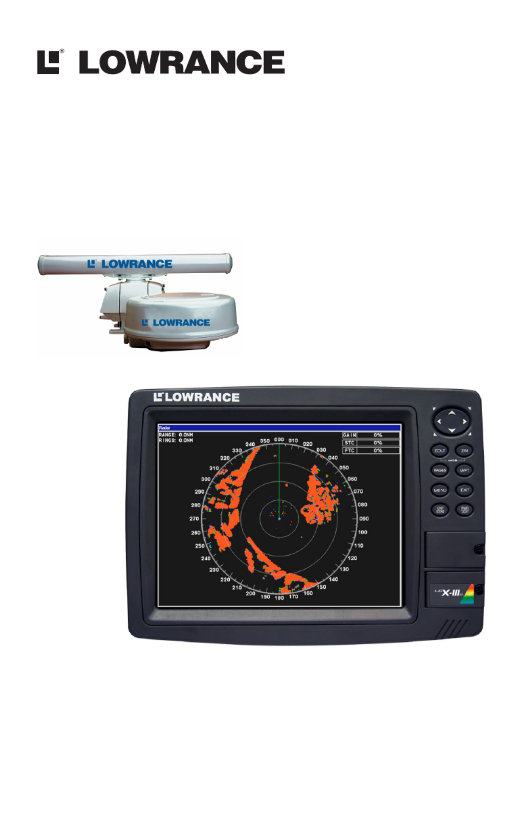
Radar at press time. On the cover: LCX-111c HD sonar/GPS unit.
For free owner's manuals and the most current information on
this product, its operation and accessories,
visit our web site:
www.lowrance.com
Lowrance Electronics Inc.
12000 E. Skelly Dr.
Tulsa, OK USA 74128-2486
Printed in USA.

i
Table of Contents
Warnings and Cautions .......................................................... iii
Section 1: Introduction............................................................. 1
Models Covered ............................................................................. 1
Update Display Unit Software ..................................................... 2
What is radar? ............................................................................... 2
Basic Radar Display Components ................................................ 4
Section 2: Radar Setup ............................................................. 7
Getting Started.............................................................................. 7
Radar Setup ................................................................................... 9
Trigger Delay Preparation........................................................ 9
Range...................................................................................... 9
Gain........................................................................................ 9
Anti-Sea Clutter .................................................................... 9
Anti-Rain Clutter ................................................................ 10
Main Bang Suppression ...................................................... 10
Trigger Delay ....................................................................... 10
Adjust Trigger Delay............................................................... 10
Adjust Main Bang Suppression.............................................. 12
Adjust Heading Line ............................................................... 13
Adjust Transmit Off Zone ....................................................... 14
Adjust Tune ............................................................................. 15
Section 3: Basic Operation .................................................... 17
Pages ............................................................................................ 17
Radar Only............................................................................... 17
Radar with Map....................................................................... 17
Radar with Sonar .................................................................... 18
Radar with Gauges.................................................................. 18
Radar Menu ................................................................................. 19
Gain .......................................................................................... 19
Anti-Sea Clutter (STC): .......................................................... 20
Anti Rain Clutter (FTC).......................................................... 20
Interference Rejection ............................................................. 21
Radar Range ............................................................................ 21
Radar Echo Expansion............................................................ 21
Echo Trail Interval .................................................................. 22
Clear Radar Trails................................................................... 22
Adjust Radar PPI Offset ......................................................... 23
Recenter Radar PPI................................................................. 23
Log Radar Data ....................................................................... 24
Record a radar log: .............................................................. 24
Change the file name: ......................................................... 24

ii
Browse data files: ................................................................ 24
Copy data files: .................................................................... 25
Delete a data file:................................................................. 26
Stop or play a data file: ....................................................... 26
Rename a data file:.............................................................. 26
Radar Setup ............................................................................. 26
Radar Orientation ................................................................... 27
Radar Color Scheme................................................................ 27
Adjust Antenna Park .............................................................. 27
Radar Information................................................................... 28
Radar Power ............................................................................ 29
Turn radar on or off:............................................................ 29
Radar Simulator ...................................................................... 29
Section 4: Advanced Operation............................................ 31
Reading the Display.................................................................... 31
Gain.......................................................................................... 31
Range Rings............................................................................. 31
Anti-Sea Clutter (STC) ........................................................... 32
Anti-Rain Clutter (FTC) ......................................................... 32
Electronic Bearing Line (EBL) ............................................... 32
Variable Range Markers......................................................... 32
Select an EBL and VRM: .................................................... 32
Reposition EBL and VRM:.................................................. 34
Remove EBL-VRM from the display: ................................. 35
Section 5: Radar Interpretation........................................... 37
Anti-Rain Clutter (FTC or Fast Time Constant) ...................... 37
Echo Trails................................................................................... 40
Typical Small Boat Targets ........................................................ 42
Shoreline Images......................................................................... 44
Recommended Reading ............................................................... 46
Appendix I: Glossary............................................................... 47
FCC Compliance ...................................................................... 50

iii
Warnings and Cautions
Caution:
Use this radar at your own risk. This radar was designed for
use as a navigation aid. It should not be used for purposes that
require precise measurements of direction, distance, topography
or location. Always compare the navigation information received
from your radar with data from other navigation aids and
sources. When a conflict arises between the navigation data from
your radar and data from other navigation aids, make sure you
resolve the conflict before proceeding with navigation. A CARE-
FUL NAVIGATOR NEVER RELIES ON ONLY ONE
METHOD TO OBTAIN NAVIGATION INFORMATION.
Caution:
International Regulations for Preventing Collisions at Sea man-
date that when radar is on a vessel, the radar must be used at
all times, regardless of weather conditions or visibility. Numer-
ous court decisions have not only ruled the radar must be used,
but that the radar operator must be knowledgeable in all opera-
tional aspects of radar performance or otherwise face a greater
risk of liability if an accident occurs.
Caution:
If you purchased an open array radar antenna, make sure it is
installed in an area free of hardware obstructions and free of po-
tential obstructions like sails, lines or other vessel components
that could intermittently intrude or be caught up in the array
antenna's rotation path.
WARNING: High Voltage Hazard
Dangerously high voltages are present within the radar
scanner unit. The unit contains no user-serviceable
parts. The cover should be removed only by a qualified
radar service technician. Technicians must exercise ex-
treme care when working inside the unit. ALWAYS re-
move power before removing the cover. Some capacitors
may take several minutes to discharge, even after
switching off the radar. Before touching the magnetron
or any high voltage components, ground them with a
clip lead. There are no internal connections or adjust-
ments necessary for installation or operation.

iv
WARNING: Microwave Radiation Hazard
The microwave energy radiated by a radar antenna is
harmful to humans, especially to the eyes. NEVER look
directly into an open waveguide or into the path of ra-
diation from an enclosed antenna. Radar and other ra-
dio frequency radiation can upset cardiac pacemakers.
If someone with a cardiac pacemaker suspects abnormal
operation, immediately turn off the radar equipment
and move the person away from the antenna. Turn off
the radar whenever it is necessary to work on the an-
tenna unit or other equipment in the beam of the radar.
WARNING: Turn Off Radar When Docked
The radar beam can be harmful to humans in close prox-
imity (within 20 yards, or 18.3 meters). When docked, be
considerate of other boats and pedestrians nearby and
remember to turn off your radar. If your boat is in a cov-
ered marina and the radar is on, a metal roof can act as
a reflector, bouncing microwave energy back at your
boat and passengers.

1
Section 1: Introduction
Thank you for buying a Lowrance Radar with the RIM 100 radar inter-
face module. Your radar consists of three main components: the radar
scanner unit (antenna), your display unit (sold separately) and the RIM
100 radar interface module which connects the scanner and display units.
WARNING:
Radar radiation can be harmful to you and bystanders.
Radar misuse or misunderstanding radar operation
could lead to a collision, which could result in property
damage, personal injury or death.
You must be familiar with the procedures and all warn-
ings and cautions described in the installation and op-
eration manuals in order to operate your radar safely
and effectively.
We know you’re eager to begin using your radar, but first, we want you to
take note of the three instruction manuals you need to read to get started.
First is the Read Me! Insert for Radar Display Unit Software Update
(part number 988-0161-022). It tells you how use the memory card in
your package to update your display unit software to make it radar-
ready. (For your convenience, this information is also repeated below.)
Second is the Radar and RIM 100 Installation Manual (part number
988-0161-001). It tells you how to install your radar's hardware.
Third is this Radar Operation Manual (part number 988-0161-011).
After installing the radar scanner unit, the RIM 100 and the new dis-
play software, you need to read this manual to learn how your display
unit and radar antenna work together.
To get the highest level of performance from your radar, it is a good
idea to keep this manual and your display unit's sonar or GPS instruc-
tion manual handy for reference.
Models Covered
This manual covers the following radar-compatible display units: LCX-
25c, LCX-26c HD, LCX-110c, LCX-111c HD sonar/GPS combos; and
GlobalMap 6500c, GlobalMap 6600c HD, GlobalMap 7500c, Global-
Map 7600c HD GPS units.
Note for GlobalMap users: Menus and function commands in your
units are identical to those shown in this manual, except your display
will not have sonar page options, sonar alarm options or sonar simula-
tor options.

2
This manual covers the following radar units: LRA-1000, LRA-1500,
LRA-2000 radomes; and LRA-4000, LRA-5000 open array radars.
Update Display Unit Software
Your display unit must have software version 1.3.0 or later to work
with radar. Depending on when you bought your display, it may require
a software update. To avoid delays in setting up your radar system,
your radar package includes an MMC or SD memory card with a basic
software upgrade.
Lowrance continues to regularly develop display enhancements and
new radar features. We strongly recommend that you periodically
check our web site for the latest free radar software updates.
If you or a friend has Internet access, log-on to www.lowrance.com,
browse to our Software page and look for the Product Updates link. If
you lack Internet access, call your dealer or Lowrance Customer Serv-
ice. Complete contact information is on the last page of this manual.
We've made it easy for you to keep up with our latest updates — just
subscribe to our free e-mail software release notices. Look for the link
at the bottom of our Product Software Upgrades web page.
Installing Software Update
1. With the display unit turned off, install the MMC card that contains
the radar software update.
2. Turn on the unit and the update will install automatically.
3. When the update is finished, the unit will power up normally. After
the updated is complete, remove the update MMC from card slot.
NOTE:
This manual assumes you have a basic understanding of your display
and its sonar and/or GPS operations. For complete instructions on
the keyboard, pages and menu structure, refer to the manual packed
with your display. That manual also explains the typographical con-
ventions and symbols we use to describe unit operations.
What is radar?
The word "radar" is an acronym for "RAdio Detecting And Ranging." In
simple terms, this is how it works:
A radio transmitter sends out a quick microwave pulse. A receiver listens
for that signal's echo when it bounces back from something in its path.

3
When the echo returns, it is processed by a computer to determine rela-
tive distance, position and bearing of the object that reflected the sig-
nal. This information is displayed on the display unit's screen. Other
boats or ships, navigational markers, landmasses and the like are re-
ferred to as targets.
By knowing how long it takes for a signal to return, the distance to a tar-
get can be determined. As the radar antenna scans through a 360 degree
rotation, it can show where the target is relative to your position. By re-
peated scans, you can see which direction another vessel is moving.
The following two pages show the basic components of your radar dis-
play screen, which is commonly referred to as the PPI, an old term from
the early days of radar.

4
Basic Radar Display Components
Your unit has three electronic bearing
lines and three variable range markers.
An enlarged example of EBLs and
VRMs is on the next page.
PPI Position
status
Display
mode
Range Range Ring
Interval
Echo Trail
status
A
nti-Rain
Clutter
A
nti-Sea
Clutter
Radar Echo
Expansion
status
Interference
Rejection
status
Ga
in l
e
v
e
l
Electronic Bearing Line position
for EBLs 1, 2 and 3. Highlighted
in white, EBL 2 is the active
bearing line.
V
ariable Range Marker position
for VRMs 1, 2 and 3. Highlighted
in white, VRM 2 is the active
range marker.
Electronic
Bearing
Lines
V
ariable
Range
Markers

5
Basic Radar Display Components
VRMs and EBLs allow you to track the distance and bearing
of multiple radar targets.
NOTE:
This manual is printed in black and white, but a free color version
(in Acrobat PDF format) is available for display or download from
the Lowrance web site. The color manual is particularly useful for
understanding Sec. 5, Radar Interpretation.
VRM1
EBL1
EBL2
EBL3
Heading line (in green)
PPI (radar screen's 360º
overhead view of the area)
Bearings, in degrees
(in Heading Up mode,
relative to bow)
VRM2 VRM3

6
Notes

7
Section 2: Radar Setup
This section will teach you how to prepare your radar for operation. Be-
fore you begin radar setup, the radar scanning unit, RIM 100 module
and display unit must all be installed and their cables connected. The
display unit must be running software version 1.3.0 or later.
WARNING:
Do NOT attempt to execute Radar Setup, while the ves-
sel is moving. Some motion from wind and wave action is
acceptable, but these setup instructions are NOT in-
tended for vessels moving across the water.
Caution:
If you are unsure or do not understand the following instruc-
tions, it is strongly recommended that an experienced radar
technician handles radar setup and the installation of radar
hardware.
Getting Started
1. After turning on the unit, press MENU|MENU, then use ↑
↑
↑
↑↑ ↓
↓
↓
↓↓ to SYSTEM
SETUP and press ENT.
Communications Port selected from System Setup menu (left). Com-
munications Port menu (right).
2. From the System Setup menu, highlight C POMMUNICATIONS ORT and
press ENT.
3. Press ↓
↓
↓
↓↓ to RADAR and press ENT, which will place an X in the radar
checkbox. The Baud Rate automatically will switch to 230400. Press
EXIT repeatedly to return to the main page display.
4. Press PAGES, then use ←
←
←
←← →
→
→
→→ to select the radar tab.
5. Press ↓
↓
↓
↓↓ to select R OADAR NLY, then press EXIT.

8
Radar only highlighted on Radar Pages menu (left). Radar menu with
Radar Power selected (right).
6. Press MENU, then use ↑
↑
↑
↑↑ ↓
↓
↓
↓↓ to select R PADAR OWER from the radar menu
and press ENT. A confirmation message will appear. Press ←
←
←
←← to select
YES and press ENT. A warm-up countdown will commence that will vary
depending on the model of radar you have.
7. After the countdown is finished, the unit will enter STANDBY mode.
8. Access the Radar Setup menu to make sure your radar display is set
to Heading Up and is set to a Full Color scheme. Press MENU, select
R SADAR ETUP and press ENT.
Radar Setup selected from Radar menu (left). Radar Setup menu with
Full Color on Black highlighted (right).
9. Highlight H UEADING P and press ENT, which will set the radar to
Heading Up.
10. To display the radar images in full color, press ↓
↓
↓
↓↓ to select RADAR
C SOLOR CHEME and press ENT.
11. Use ↑
↑
↑
↑↑ ↓
↓
↓
↓↓ to highlight one of the three full color options and press
ENT. Press EXIT to return to the main page display.

9
Radar Setup
The Radar Setup menu allows you to setup and adjust radar settings,
like Transmit Off Zone and Antenna Park. Most of the settings in the
Radar Setup menu will only have to be set once, but we recommend you
check the settings periodically for general maintenance.
NOTE:
Before starting radar setup, take your vessel out on open water
with fairly calm seas, like an open bay.
The three setup features we want to modify are Adjust Trigger Delay,
Adjust Main Bang Suppression and Adjust Heading Line.
We will set them up in that order, but before making any adjustments,
make sure the display is set to a range of 1/8 nautical miles and that
Gain, Anti-Sea Clutter (STC), Anti-Rain Clutter (FTC), Main Bang
Suppression and Trigger Delay all have been set to zero percent.
Trigger Delay Preparation
Range
1. To reset range to 1/8 nm, make sure you are on the Radar Only page
and press MENU.
2. Use ↑
↑
↑
↑↑ ↓
↓
↓
↓↓ to select R RADAR ANGE and press ENT, which will call up the
Radar Range list. Press ↑
↑
↑
↑↑ to select 1/8 nm and press ENT. You also can
set the range to 1/8 nm from the radar screen by using the ZIN and
ZOUT keys.
Gain
1. To set Gain to zero, press MENU, select GAIN and press ENT.
2. That will launch the Gain vertical scrollbar. Press ↓
↓
↓
↓↓ until the Gain is
set to zero percent. Press EXIT. (Notice the corresponding value in the
upper right-hand corner of the screen.)
NOTE:
When adjusting Gain back to a useable level, increase the level un-
til you see a light peppering on the display. Also remember, you will
have to adjust gain every time you change ranges.
Anti-Sea Clutter
1. To set Anti-Sea Clutter to zero, press MENU, select ANTI-SEA CLUTTER
(STC) and press ENT.
2. That will launch the Anti-Sea Clutter vertical scrollbar. Press ↓
↓
↓
↓↓ until
the Anti-Sea Clutter is set to zero percent. Press EXIT. (Notice the cor-
responding value in the upper right-hand corner of the screen.)

10
Anti-Rain Clutter
1. To set Anti-Rain Clutter to zero, press MENU, select ANTI-RAIN CLUTTER
(FTC) and press ENT.
2. That will launch the Anti-Rain Clutter vertical scrollbar. Press un-
↓
↓
↓
↓↓
til the Anti-Rain Clutter is set to zero percent. Press EXIT. (Notice the
corresponding value in the upper right-hand corner of the screen.)
Main Bang Suppression
1. To set Main Bang Suppression to zero, press MENU, select RADAR
SETUP and press ENT.
2. Press →
→
→
→→ ↓
↓
↓
↓↓| to ADJUST MAIN BANG SUPPRESSION and press ENT. That will
call up the Main Bang Suppression vertical scrollbar.
3. Press ↓
↓
↓
↓↓ until Main Bang Suppression is set to zero percent. Press
EXIT.
Trigger Delay
1. To set Trigger Delay to zero, press MENU, select and RADAR SETUP
press ENT.
2. Press →
→
→
→→ ↓
↓
↓
↓↓| to ADJUST T DRIGGER ELAY and press ENT. That will call up
the Adjust Trigger Delay vertical scrollbar.
3. Press ↓
↓
↓
↓↓ until Trigger Delay is set to zero percent. Press EXIT.
Adjust Trigger Delay
This feature eliminates the time lag between real radar returns and the
time it takes data to be processed by the radar software, a common is-
sue with all radars.
Caution:
If you have any doubt about your understanding of the Trigger
Delay feature, you should have it set up by a qualified radar
technician.
1. The radar should already be in STANDBY mode, so press PWR for 2
seconds to switch the radar into transmission mode. A confirmation
message will appear, press ←
←
←
←← to select YES.
2. Press MENU, then select GAIN and press ENT, which will call up the
Gain vertical control bar. Press ↑
↑
↑
↑↑ to increase the Gain level to around
15%. One or two red rings with blue borders should be visible on the
screen, depending on the wattage of your radar antenna.
3. Now from the Radar Setup menu, press →
→
→
→→ ↓
↓
↓
↓↓| to ADJUST TRIGGER DELAY,
then press ENT. The Adjust Trigger Delay vertical scrollbar will appear.

11
The 2 kW models, the LRA-1000 and LRA-1500, will have only one ring
on the display. The 4 kW radars — LRA-2000, LRA-4000 and LRA-5000
— will have two rings on the display. See the following figures.
Before adjusting the Trigger Delay for 4 kW radars, two rings will be
shown on the screen (left). As Trigger Delay is increased, the larger
ring will start to get smaller. The small ring will disappear (right).
You may have to increase gain in the previous step if the rings are not
visible. Increase gain until you have solid red rings shown on the
screen, like in the preceding example. Increasing Gain too much can
cause distortion of the rings.
4. Press ↑
↑
↑
↑↑ to increase the level of Trigger Delay, which will decrease the
size of the ring. If you have a 4 kW radar, as the large ring decreases in
size, the smaller ring in the center of the screen will disappear, leaving
only one ring.
Increase Trigger Delay to diminish the size of the red ring (left). To set
Trigger Delay correctly, reduce the ring to as small a size as possible,
while keeping a black circle in the middle (enlarged view, right).
In either case, continue to increase the Trigger Delay level until the
ring is as small as possible, while keeping a black circle in the middle.
Every radar is different, but typically, a setting between 35 and 42 per-
cent will get the job done.

12
If you over apply the Trigger Delay, the black circle will disappear. De-
crease the Trigger Delay level and it will reappear.
3. Press EXIT to return to the main page display.
Adjust Main Bang Suppression
Main Bang Suppression is only for 4kW units — LRA 2000, LRA 4000 and
LRA 5000. This feature filters out electronic noise close to your vessel. It
gives you control of radar sensitivity in the area surrounding your ves-
sel, approximately 180 feet in all directions.
Before making any adjustments to Main Bang Suppression, take your
vessel out on open water with fairly calm seas, like an open bay.
Caution:
If you have any doubt about your understanding of the Main
Bang Suppression feature, you should have it set up by a quali-
fied radar technician.
1. From the Radar Setup menu, press →
→
→
→→ ↓
↓
↓
↓↓| to ADJUST MAIN ANG B SUP-
PRESSION and press ENT. That will launch the Main Bang Suppression
vertical scrollbar.
2. The small red ring we adjusted during Trigger Delay setup will still
be on the display.
3. Press ↑
↑
↑
↑↑ slowly — Main Bang Suppression can be sensitive — to in-
crease the Main Bang Suppression level so the red ring becomes as thin
as possible.
4. Press ↓
↓
↓
↓↓ to slowly decrease the level until you have returned the red
ring back to its thinnest point. Every radar is different, but typically, a
setting between 2 and 8 percent will be satisfactory.
NOTE:
In many cases, depending on the radar unit you have, over applying
Main Bang Suppression can make the ring disappear, start to make
it wider or the ring can get to a point where it is as small as it will
get. At this point, increasing the main bang level will not change
the red ring.
If the red ring does not does not decrease in size when increasing
the suppression level, reduce the level until you see a slight in-
crease in the size of the ring, then leave it at that setting.

13
Main Bang Suppression begins with the same red ring we resized dur-
ing Trigger Delay setup (left). Slowly increase Main Bang Suppression
to make the ring as thin as possible (enlarged view, right).
5. Press EXIT to clear the scrollbar from the screen. Now reset Gain,
Anti-Sea Clutter and Anti-Rain Clutter back to a desired level.
Adjust Heading Line
The Heading Line command is used to make sure the green heading
line (zero point) on your display is lined up with the bow of your vessel.
(Before heading line adjustment) (After heading line adjustment)
The bow of the ship is lined up with the tip of the peninsula (left), but the
green heading line is not. Adjusting the heading line will allow you to align
the direction of the heading line with the direction of the bow (right).
1. Line up the bow of your vessel with a point of reference, like a penin-
sula, lighthouse or other stationary target.
2. From the Radar Setup menu, press →
→
→
→→ to select ADJUST HEADING LINE
and press ENT. That will place an arrow on each side of the green
Heading Line.

14
3. Use to adjust the position of the
←
←
←
←← →
→
→
→→ green heading line, so its line
to the reference point's radar image matches your bow's actual line to
the reference point.
4. Press EXIT to remove the heading line arrows from the display.
Adjust Transmit Off Zone
The Transmit Off Zone is a feature that allows you to select an area in
the radar's 360° transmission path where the radar beam will not be
transmitted.
WARNING:
ALL targets inside the Transmit Off Zone will NOT be
displayed on the screen. This will create a blind spot
within the off zone!
Transmit Off Zone is shown in bright red; the remaining area of the
PPI is considered the Transmit Zone. Color is exaggerated here for
clarity; on-screen, the off zone actually appears in a dimmer shade so
as not to distract from target images in the transmit zone. Dialog box
values at upper right are in degrees, relative to the heading line.
Caution:
Preventing the main beam or lobe from transmitting through the
Transmit Off Zone will diminish the amount of radiation
broadcast in that area, but it WILL NOT protect you from radia-
tion transmitted by the side lobes of the radar antenna.
To avoid radiation exposure, be sure to follow the installation
instructions, which require the radar to be installed at least 1
foot above all persons.
Transmit Of
f
Zone
Transmit
Zone

15
1. From the Radar Setup menu, press →
→
→
→→ ↓
↓
↓
↓↓| to select ADJUST TRANSMIT OFF
ZONE and press ENT. That will launch the Adjust Transmit Off Zone
dialogs in the upper right-hand corner of the screen.
2, Use ↑
↑
↑
↑↑ ↓
↓
↓
↓↓ , ←
←
←
←← →
→
→
→→ to set up the Transmit Off Zone in the desired area.
The zone will be colored red on the radar display.
3. Press EXIT when the Transmit Off Zone is set. To remove the zone,
repeat Step 1, then set both dialog boxes back to zero and press EXIT.
Adjust Tune
Tuning should require no adjustment during the life of the unit. We
strongly recommend you do NOT adjust Tune settings yourself.
This feature is intended for use only by trained technicians. If for some
reason you need to use this function, consult your dealer or customer
service about the software updates necessary for tuning.

16
Notes

17
Section 3: Basic Operation
Pages
The Radar Page has four display options: Radar Only, Radar with Map,
Radar with Sonar and Radar with Gauges. GPS only units do not sup-
port the Radar with Sonar page, so they have three display options:
Radar Only, Radar with Map and Radar with Gauges.
Radar Page Menu with Radar Only selected.
To access Radar page display options:
1. Press PAGES, then use ←
←
←
←← →
→
→
→→ to highlight the radar tab.
2. Use to select the desired
↑
↑
↑
↑↑ ↓
↓
↓
↓↓ radar page configuration.
3. Press EXIT when the desired display option is highlighted.
Radar Only
Choose Radar Only if you want to display the radar full screen.
Radar with Map
To keep an eye on radar and GPS data at the same time, select Radar
with Map.

18
Radar Only option (left) with Radar with Map display (right).
Radar with Sonar
The Radar with Sonar option allows you to monitor radar information,
while viewing sonar returns. Not available on GPS only units.
Radar with Gauges
The Radar with Gauges display will split the screen between the radar
page and the gauge page. The gauge page can be customized to display
sonar and GPS information in digital and analog gauge formats.
NOTE:
For instructions on customizing the gauges window with digital in-
formation or analog gauges, refer to the overlay data entry in your
unit's instruction manual.
Radar with Sonar option (left). Radar with Gauges display (right).
NOTE:
When more than one page display is on the screen at the same
time, press PAGES|PAGES to switch the Active status between
windows. The title bar at the top of the window will be blue when
the window is active. The only exception is the map page, which
will display "Active Map" at the top of the map.

19
Radar Menu
When a radar page is the active page, you can access the radar menu by
pressing MENU MENU MENU. To access the main menu, press | .
Radar Menu.
Gain
This is used to adjust the sensitivity of the receiver. Setting Gain to a
low level will clear up some of the clutter on the screen, but also could
eliminate some desired echoes. A high level of the Gain, allows you to
see greater detail around you, but will clutter the screen.
NOTE:
When adjusting Gain back to a useable level, increase the level un-
til you see a light peppering of echoes on the display. Also remem-
ber, you will have to adjust gain every time you change ranges.
To adjust Gain:
1. Highlight GAIN on the radar menu and press ENT. That will launch
the Gain vertical scrollbar.
2. Use ↑
↑
↑
↑↑ ↓
↓
↓
↓↓ to adjust the Gain to a desired level. Press EXIT to remove
the scrollbar from the screen.

20
Gain vertical scrollbar (left) with Anti-Sea Clutter scrollbar (right).
Anti-Sea Clutter (STC):
This lowers receiver sensitivity at shorter ranges to reduce or eliminate
echoes that reflect back at the antenna due to wave action close to the
vessel.
Caution
Increasing STC may reduce or eliminate weak echoes, like small
vessels. Use only the minimum amount needed, then check back
periodically to see if the STC level may be decreased.
To adjust Anti-Sea Clutter:
1. Select ANTI-SEA CLUTTER from the radar menu and press ENT. The Anti-
Sea Clutter vertical scrollbar will appear.
2. Use ↑
↑
↑
↑↑ ↓
↓
↓
↓↓ to adjust Anti-Sea Clutter to a desired level. Press EXIT to
remove the scrollbar from the screen.
Anti Rain Clutter (FTC)
This is used to reduce or eliminate massive numbers of small echoes
that clutter the display during rain or snow storms.
To adjust Anti-Rain Clutter:
1. Highlight ANTI-SEA CLUTTER on the radar menu and press ENT. The
Anti-Sea Clutter vertical scrollbar will appear.
WARNING:
Increasing FTC may reduce or eliminate weak echoes,
like those from small vessels. Use only the minimum
amount needed, then check back periodically to see if
the FTC level may be decreased.
2. Use ↑
↑
↑
↑↑ ↓
↓
↓
↓↓ to adjust the Anti-Rain Clutter setting to a desired level.
Press EXIT to remove the scrollbar from the screen.

21
Anti-Rain Clutter vertical scrollbar (left) with Interference Rejection
scrollbar (right).
Interference Rejection
This feature filters out signals from other radars close to your location.
To adjust Interference Rejection:
1. Select I RNTERFERENCE EJECTION from the radar menu and press ENT.
That will launch the Interference Rejection vertical scrollbar.
2. Use ↑
↑
↑
↑↑ ↓
↓
↓
↓↓ to adjust the Interference Rejection setting to a desired level.
Press EXIT to remove the scrollbar from the screen.
Radar Range
This feature allows you to expand the area shown on the display unit,
which is helpful when you want to see targets a great distance from you.
You also can decrease the range to focus on targets closing in on you.
NOTE:
When switching radar ranges, you likely will need to adjust Gain,
STC and FTC settings to achieve optimum performance.
To adjust radar range:
1. Select R RADAR ANGE from the radar menu and press ENT, which will
launch the radar range list.
2. Use ↑
↑
↑
↑↑ ↓
↓
↓
↓↓ to select the desired range and press ENT. The range you
chose is now in use on the radar display.
Tip:
Once you are comfortable with the various radar range options, you
can more easily switch ranges by pressing the ZIN or ZOUT keys.
Radar Echo Expansion
This feature will make weak signals more visible on the display by
lengthening radar echoes.

22
Radar Range selected (left). List of radar ranges (right).
To turn on or turn off Radar Echo Expansion:
Highlight R E EADAR CHO XPANSION on the radar menu, then press ENT to
turn it on (check) or turn it off (uncheck). Press EXIT to clear the radar
menu. Radar Echo Expansion is good for seeing weak echo returns —
like birds — at a distance.
Remember, when Echo Expansion is on, all signals on the display will
be enlarged, including clutter.
Echo Trail Interval
This option allows you to compile a history (trail) of the movements of
all radar targets via preset intervals.
To adjust Echo Trail Interval
1. Select E TCHO RAIL INTERVAL from the radar menu and press ENT, which
will launch the Echo Trail Interval menu.
2. The Echo Trail Interval menu will display a series of intervals with
options ranging from Continuous to Off. Use ↑
↑
↑
↑↑ ↓
↓
↓
↓↓ to highlight the de-
sired interval and press ENT. Press EXIT to get back to clear the menu.
NOTE:
This feature is best used in open water or when your vessel is sta-
tionary and you are tracking a moving target. If Echo Trail Interval
is on and your vessel is moving, the display will be crowded with
trails for every target, including stationary targets, like lighthouses
and land.
Clear Radar Trails
This feature is used to clear radar trails created with the Echo Trail
Interval command.
To clear radar trails:
Highlight C R TLEAR ADAR RAILS on the radar menu and press ENT. All ra-
dar trails are now cleared off the radar display.

23
Adjust Radar PPI Offset
Adjusts vertical and horizontal offset of the PPI, allowing you to see
more of what is in front, behind or on either side of you.
To Adjust Radar PPI Offset:
1. Select A RDJUST ADAR PPI OFFSET from the radar menu and press ENT.
2. Four arrows will surround the PPI. Use ↑
↑
↑
↑↑ ↓
↓
↓
↓↓ , ←
←
←
←← →
→
→
→→ to move the Plan
Position Indicator (PPI) to the desired location. Press ENT to keep it at
its new location or press EXIT to return the PPI to its default position.
Adjust Radar PPI Offset selected (left). PPI moved to the left of center
of the radar display (right). Notice when the PPI is moved, Off Center
will appear in the upper left-hand corner of the screen.
Recenter Radar PPI
Resets to zero the vertical and horizontal offset of the Plan Position In-
dicator (PPI), moving it back to the center of the display.
Recenter Radar PPI highlighted (left). PPI has moved back into the
center of the radar display (right).
To recenter radar PPI:
Select R RECENTER ADAR PPI on the radar menu and press ENT. The PPI is
moved back to the center of the display. Press EXIT to return to the
main menu.

24
Log Radar Data
If your unit has a hard drive (LCX-26cHD, LCX-111cHD, GlobalMap
6600cHD & GlobalMap 7600cHD) the Log Radar Data feature allows
you to save radar logs. Saving a radar log allows you to reuse the log in
the unit's simulator, which can aid you in being more proficient at ra-
dar interpretation.
To record a radar log:
1. Select L R DOG ADAR ATA from the radar menu, then press ENT. The Ra-
dar Chart Logging menu will appear.
2. Press ENT to start logging.
Log Radar Data selected from radar menu.
NOTE:
Remember — you will NOT be able to log radar data, unless you
have a unit with a hard drive. The following units can log radar
data: LCX-26cHD, LCX-111cHD, GlobalMap 6600cHD & Global-
Map 7600cHD.
The Chart Logging menu also allows you to change the file name or
browse through data files on your MMC or SD card.
To change the file name:
1. From the chart logging menu, press ↓
↓
↓
↓↓ to File Name and press ENT.
2. Press ↑
↑
↑
↑↑ ↓
↓
↓
↓↓ to change the first letter, then press →
→
→
→→ to move to the next
letter. Repeat these steps until the desired name has been entered.
Press ENT. Press EXIT to return to the main page display.
To browse data files:
1. Select B FROWSE ILES from the chart logging menu and press ENT.
2. Use ↑
↑
↑
↑↑ ↓
↓
↓
↓↓ to scroll through the available files. Press EXIT EXIT| to re-
turn to the main page display.

25
Browse Files selected from the Radar Chart Logging menu (left).
Browse Files menu (right).
When you select a file from the file browse menu, you can copy, delete,
play or stop playing a data file.
To copy data files:
1. Select the desired file from the Browse Files menu and press ENT.
2. The File Information window will appear with three buttons, copy,
delete and either stop or play.
NOTE:
Stop will only appear in the File Information menu if the file is cur-
rently being used by the unit. Selecting STOP will bring to a halt the
unit's use of the file. When the file is no longer being used, the stop
button will be replaced with the play button. Select PLAY to reacti-
vate the file.
File Information window (left). The Copy To window (right).
3. Select COPY to save the file to an MMC or SD card. That will launch
the Copy To window, which allows you to choose where you want to
save the file. Use ←
←
←
←← →
→
→
→→ to select your MMC or SD card and press ENT.

26
4. Next use ↑
↑
↑
↑↑ ↓
↓
↓
↓↓ to highlight the C FOPY ROM dialog box. Select your unit's
hard drive as the Copy-From location and press ENT.
5. Highlight the COPY button and press ENT.
To delete a data file:
1. Highlight DELETE from the File Information window and press ENT.
2. A confirmation message will appear. Press ←
←
←
←← to YES and press ENT.
To stop or play a data file:
1. Select the desired file from the Browse Files menu and press ENT.
2. If the file is currently in use, the Stop button will be on the menu. If
the file is not in use or if you halt its use by activating the stop com-
mand, the Play button will be displayed.
Stop button highlighted in File Information window (left). Play button
selected in File Information window (right).
3. To stop playing the chart currently in use, highlight STOP and press
ENT. The play button will replace the stop button on the File Informa-
tion window. Press EXIT to return to the main page display.
4. To play the chart again, highlight PLAY and press ENT. Press EXIT to
return to the main page display. The radar simulator will automati-
cally be turned on if you play a chart from the File Information menu.
To rename a data file:
1. Highlight NAME at the top of the File Information menu and press
ENT.
2. Press ↑
↑
↑
↑↑ ↓
↓
↓
↓↓ to change the first letter, then press →
→
→
→→ to move to the next
letter. Repeat these steps until the desired name has been entered.
3. Press EXIT repeatedly to get back to the main page display.
Radar Setup
The Radar Setup menu allows you to set up and adjust basic radar set-
tings, like Heading Line, Trigger Delay, Main Bang Suppression,

27
Transmit Off Zone and Tune, all of which are addressed in the section
on Radar Setup. You can also modify Radar Orientation, Radar Color
Scheme and Antenna Park from the Radar Setup menu.
Radar Orientation
Displays the orientation of your radar, which by default is set to
Heading Up.
Radar Color Scheme
Your radar has eight color options: Full Color on Black, Full Color on
Gray, Full Color on White, Green on Black, Yellow on Black, Yellow on
Blue, Night Viewing and Green CRT.
When using full color mode on the radar display, the strongest targets
will be displayed in red, weaker targets will be shown in green and the
weakest returns will be colored blue.
Radar Setup selected on System Setup menu (left). Radar Color
Scheme highlighted on Radar Setup menu (right).
To adjust the Radar Color Scheme:
1. From the Radar Setup menu, press ↓
↓
↓
↓↓ to R C SADAR OLOR CHEME and
press ENT. The Radar Color Scheme menu will appear.
2. Press ↑
↑
↑
↑↑ ↓
↓
↓
↓↓ to select the desired color scheme, then press ENT. Press
EXIT to return to the main page display.
Adjust Antenna Park
This feature allows users to adjust their open array antenna so it will
come to a stop in a desired position.
NOTE:
Each antenna is different, so there is no recommended setting for
Antenna Park. You must use the trial and error method of making
an adjustment, then check the result. Repeat that process until the
antenna comes to a stop in the desired position.

28
Selecting Adjust Antenna Park will place a dialog box in the upper
right-hand corner of the screen. Use Arrow keys to adjust it.
To adjust Antenna Park:
1. Make sure the vessel is not moving, then, from the Radar Setup
menu, press →
→
→
→→ ↓
↓
↓
↓↓| to ADJUST ANTENNA PARK and press ENT. That will dis-
play the Adjust Antenna Park dialog box in the upper right-hand cor-
ner of the screen.
2. Use ←
←
←
←← →
→
→
→→ to input the desired setting.
3. Test your settings by putting the radar into STANDBY Mode. Ob-
serve the location where the antenna stops. Repeat the steps above un-
til the desired location is achieved. Press EXIT to return to the main
page display.
Remember; you must not be moving when attempting to adjust Antenna
Park settings. Your vessel must be stationary for the antenna to stop in
the desired position. If you attempt to adjust Antenna Park while the
vessel is underway or if the antenna stops in the desired position and
you begin moving, the wind will move the antenna out of position.
Radar Information
Displays information about the radar, like radar model, radar status
and software information.
To access radar information:
1. Select R IADAR NFORMATION on the radar menu, then press ENT.
Produktspecifikationer
Varumärke: | Lowrance |
Kategori: | Fartygsradar |
Modell: | LRA1000 |
Behöver du hjälp?
Om du behöver hjälp med Lowrance LRA1000 ställ en fråga nedan och andra användare kommer att svara dig
Fartygsradar Lowrance Manualer

7 September 2024

29 Augusti 2024

26 Augusti 2024

26 Augusti 2024

21 Augusti 2024

21 Augusti 2024

20 Augusti 2024

20 Augusti 2024

18 Augusti 2024

16 Augusti 2024
Fartygsradar Manualer
- Fartygsradar Garmin
- Fartygsradar Navman
- Fartygsradar Simrad
- Fartygsradar Furuno
- Fartygsradar JRC
- Fartygsradar Raymarine
Nyaste Fartygsradar Manualer

8 Oktober 2024

8 Oktober 2024

4 Oktober 2024

25 September 2024

25 September 2024

12 September 2024

10 September 2024

9 September 2024

8 September 2024

4 September 2024