Midea MV8M-160WV2RN8 Bruksanvisning
Läs nedan 📖 manual på svenska för Midea MV8M-160WV2RN8 (46 sidor) i kategorin Värmepump. Denna guide var användbar för 4 personer och betygsatt med 4.5 stjärnor i genomsnitt av 2 användare
Sida 1/46
Original instructions
Thank you very much for purchasing our air conditioner.
Before using your air conditioner, please read this manual carefully and retain it for future reference.
The figures shown in this manual are for reference purposes only and may be slightly different from the actual product.
IMPORTANT NOTE:
INSTALLATION AND
OWNER’S MANUAL
Full DC Inverter V8 R32 Series Mini VRF (ODU)
CONTENTS
01
25
OWNER’S MANUAL
1
2
27
3
4
740
27
26
PRECAUTIONS
PACKING BOX
OUTDOOR UNIT
PREPARATIONS BEFORE INSTALLATION
31
5
635
OUTDOOR UNIT INSTALLATION
ELECTRICAL WIRING
46
8
9
25
1
216
17
19
01
48
COMMISSIONING
CONFIGURATION
PRECAUTIONS ON REFRIGERANT LEAKAGE
10 49
TURN OVER TO CUSTOMER
11 50
TECHNICAL DATA
INSTALLATION MANUAL
BEFORE OPERATING
OPERATIONS
3
4
MAINTENANCE AND REPAIR
TROUBLESHOOTING
24
5 CHANGING INSTALLATION SITE
24
6 DISPOSAL
NOTE
The single-phase units comply with IEC 61000-3-12.
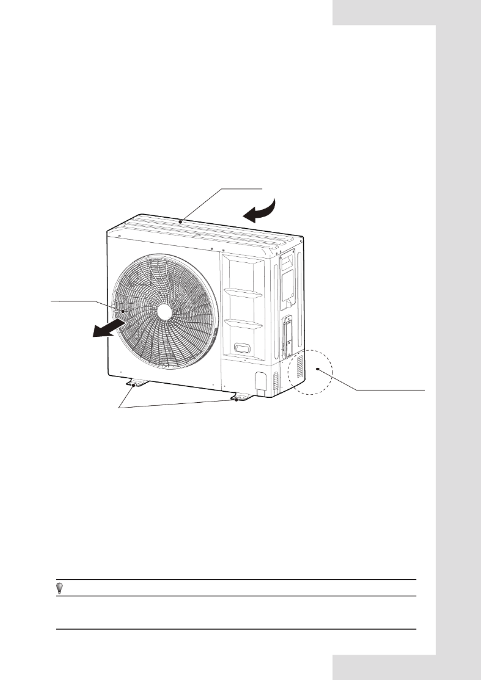
The figures in this manual are for explanation purposes only. They may be slightly different from the air conditioner you
purchased (depending on the model). The actual shape shall prevail.
Refrigerant pipe
connector
Air inlet
Mounting
bracket
Air outlet
01
OWNER’S MANUAL 1.1 Overview
Read these instructions carefully before
operation. And keep this manual handy for
future reference.
i
Any person who is involved with working on or
opening a refrigerant circuit should hold a
current valid certificate from an
industry-accredited assessment authority,
which authorizes their competence to handle
refrigerants safely in accordance with an
industry recognized assessment credential.
Servicing shall only be performed as
recommended by the equipment manufacturer.
Maintenance and repair requiring the
assistance of other skilled personnel shall be
carried out under the supervision of a person
competent in the use of flammable refrigerants.
1 BEFORE OPERATING
To prevent injury to the user or others and property
damage, the following instructions must be followed.
Ignoring these instructions may cause harm or damage.
The safety precautions listed here are divided into the
following types. They are quite important, so be sure to
follow them carefully.
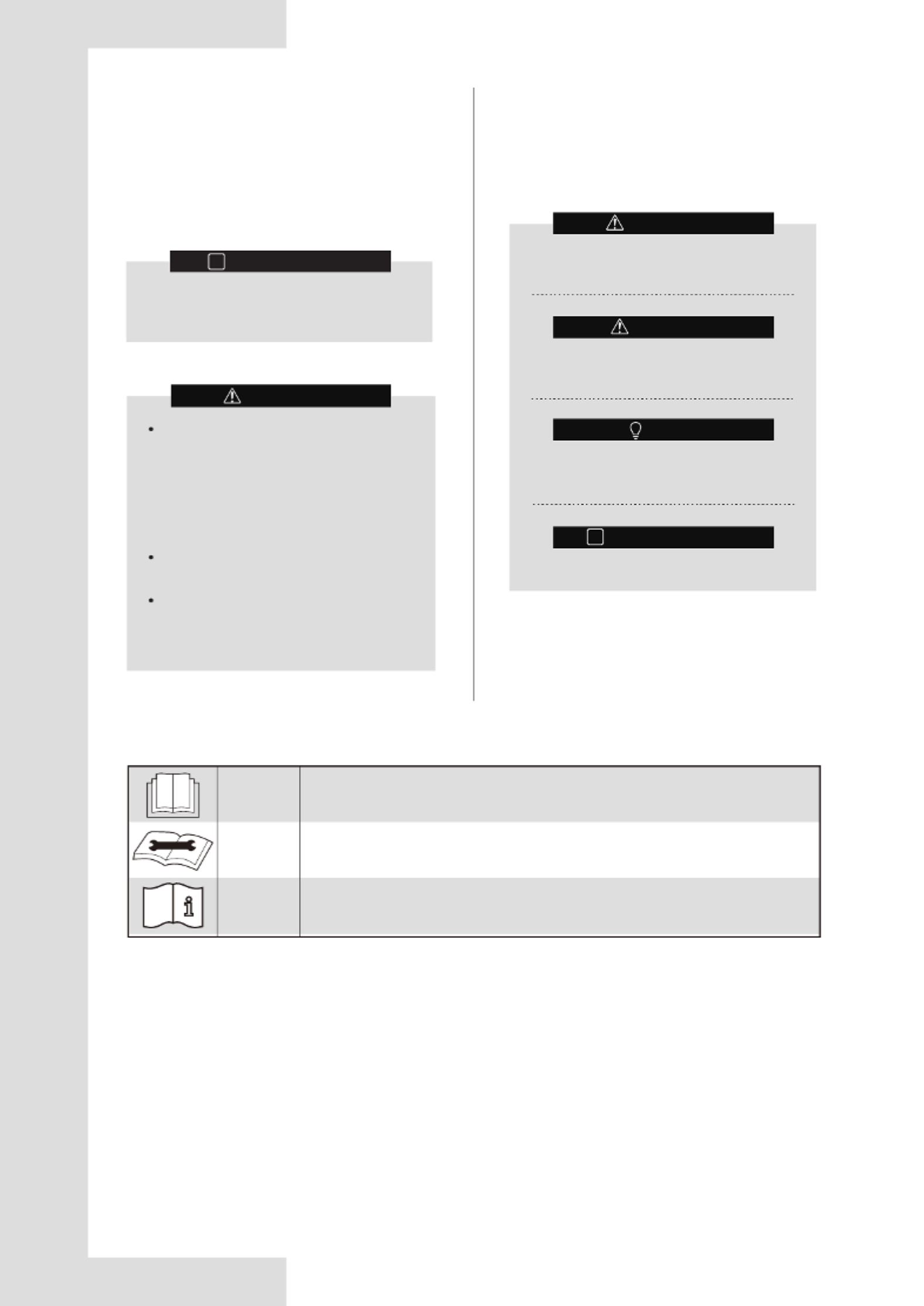
Meanings of WARNING, CAUTION NOTE and ,
INFORMATION symbols.
Explanation of symbols displayed on the application
CAUTION
CAUTION
CAUTION
This symbol indicates that the operation manual should be read carefully.
This symbol indicates that service personnel should be handling this equipment
while referencing the installation manual.
This symbol indicates that additional information is available in documents such
as the operating manual or installation manual.
A situation that may lead to severe injury or
death.
A situation that may lead to mild or moderate
injury.
A situation that may cause damage to the
equipment or loss of property.
Indicates a useful hint or additional information.
i
INFORMATION
INFORMATION
WARNING
WARNING
CAUTION
NOTE
02
1.2 Important Safety Information
This appliance can be used by children
ages 8 and above and persons with
reduced physical, sensory or mental
capabilities or who lack experience and
knowledge only if they are supervised or
have been given instruction concerning the
use of the appliance in a safe way and
understand the hazards involved.
Children shall not play with the appliance.
Children shall not clean or maintain the
appliance without supervision.
This appliance is not intended for use by
persons (including children) with reduced
physical, sensory or mental capabilities, or
persons who lack experience and
knowledge, unless they are supervised or
have been given instructions concerning
the use of the appliance by a person
responsible for their safety.
– Children should be supervised to ensure that
they do not play with the appliance.
– The split units shall only be connected to an
appliance compatible with the same refrigerant.
– The units 8-18 kW are split unit air
conditioners, complying with split unit
requirements of this International standard,
and must only be connected to the units that
have been confirmed as complying with the
corresponding split unit requirements of this
International standard.
Ask your dealer to assist in the installation
of the air conditioner.
Incomplete installation performed by yourself
may result in a water leakage, electric shock,
and fire.
Ask your dealer for assistance with
improvement, repair, and maintenance.
Incomplete improvement, repair, and
maintenance may result in a water leakage,
electric shock, and fire.
To avoid electric shock, fire or injury,
please turn off the power supply and call
your dealer for instructions if you detect
any abnormalities such as a burning smell
Never let the indoor unit or the remote
controller get wet.
This could lead to electric shock or fire.
Never press the button of the remote
controller with a hard, pointed object.
The remote controller may be damaged.
Never replace a fuse with a fuse that has an
incompatible rated current or other wires
when a fuse blows out.
The use of wire or copper wire may cause the
unit to break down or cause a fire.
Exposing your body to the air flow of the
air conditioner for long periods of time may
be harmful to your health
Do not insert fingers, rods or other objects
into the air inlet or outlet.
When the fan is in operation, it will cause injury.
Never use a flammable spray, such as hair
spray or lacquerer paint, near the unit.
It may cause a fire.
Prior to beginning work on systems
containing flammable refrigerants, safety
checks are necessary to minimize the risk
of ignition
When repairing the refrigerating system,
comply with the following precautions prior
to conducting work on the system:
– shall be undertaken according to controlled
procedures so as to minimize the risk of the
presence of flammable gases or vapors while
the work is being performed.
– All maintenance staff and others working in
the local area shall be instructed on the nature
of work being carried out. Work in confined
spaces shall be avoided.
– The area shall be checked with an
appropriate refrigerant detector prior to and
during work, to ensure the technician is aware
of potentially toxic or flammable environment.
Ensure that the leak detection equipment
being used is suitable for use with all
applicable refrigerants, i.e. non-sparking,
adequately sealed or intrinsically safe.
– If any hot work is to be conducted on the
refrigerating equipment or any associated
parts, appropriate fire extinguishing equipment
shall be available and easily accessible. Have
a dry powder or CO2 fire extinguisher adjacent
to the charging area.
– When carrying out work in relation to a
refrigerating system that involves exposing any
pipe work, no sources of ignition shall be used
in such a manner that it may lead to the risk of
fire or explosion. All possible ignition sources,
including cigarette smoking, should be kept
sufficiently far away from the site of
installation, repair, or removal and disposal of
the unit, during which refrigerant can possibly
be released into the surrounding space. Prior
to beginning work, the area around the
equipment is to be surveyed to make sure that
there are no flammable hazards or ignition
risks. “No Smoking” signs shall be clearly
displayed.
Ensure that the area is in the open or that it
is adequately ventilated before opening the
system or conducting any hot work. A
degree of ventilation shall continue during
the period that the work is carried out. The
ventilation should safely disperse any
released refrigerant and preferably expel it
externally into the surroundings.
Where electrical components are being
changed, they shall be fit according to their
purpose and to the correct specification. At
all times the manufacturer’s maintenance
and service guidelines shall be followed. If
in doubt, consult the manufacturer’s
technical department for assistance. The
following checks shall be applied to
installations using flammable refrigerants:
– The actual refrigerant charge is in
accordance with the room size within which the
refrigerant containing parts are installed;
– The ventilation machinery and outlets are
operating adequately and are not obstructed;
– If an indirect refrigerating circuit is being
used, the secondary circuit shall be checked
for the presence of refrigerant;
– Equipment marking must remain visible and
legible. Markings and signs that are illegible
shall be corrected;
WARNING
WARNING
03
– Refrigerating pipe or components are
installed in a position where they are unlikely
to be exposed to any substances which may
corrode refrigerant containing components,
unless the components are constructed of
materials that are inherently resistant to
corrosion or are suitably protected against
corrosion.
Repair and maintenance of electrical
components shall include initial safety
checks and component inspection
procedures. If a fault exists that could
compromise safety, then no electrical
supply shall be connected to the circuit
until the fault has been dealt with
satisfactorily. If the fault cannot be
corrected immediately but it is necessary to
continue operation, an adequate temporary
solution shall be used. This shall be
reported to the owner of the equipment so
that all parties are advised. Initial safety
checks shall include:
– That capacitors are discharged: this shall be
done in a safe manner to avoid the possibility
of sparking;
– That no live electrical components and wiring
are exposed while charging, recovering or
purging the system;
– That there is continuity of grounding.
When repairing sealed components, all
electrical supplies shall be disconnected
from the equipment being worked upon
prior to any removal of sealed covers, etc.
If it is absolutely necessary to have an
electrical supply to the equipment during
servicing, then a permanently operating
form of leak detection shall be installed at
the most critical point to warn of a
potentially hazardous situation.
Particular attention shall be paid to the
following to ensure that by working on
electrical components, the casing is not
altered in such a way that the level of
protection is affected. This shall include
damage to cables, an excessive amount of
connections, terminals not made to their
original specification, damage to seals,
incorrect fitting of glands, etc.
Ensure that the apparatus is mounted
securely.
Ensure that seals or sealing materials have
not degraded to the point that they no
longer prevent the ingress of flammable
materials. Replacement parts shall conform
with the manufacturer’s specifications.
Do not apply any permanent inductive or
capacitance loads to the circuit without
ensuring that this will not exceed the
permissible voltage and current permitted
for the equipment in use.
Intrinsically safe components are the only
types that can be worked on while live in
the presence of flammable gases. The test
apparatus shall be at the correct rating.
Replace components only with parts
specified by the manufacturer. Other parts
may result in the ignition of refrigerant
which has leaked into the surroundings.
Check that cabling will not be subject to
wear, corrosion, excessive pressure,
vibration, sharp edges or any other adverse
environmental effects. The check shall also
take into account the effects of aging or
continual vibration from sources such as
compressors or fans.
Under no circumstances shall potential
sources of ignition be used while searching
for or detection of refrigerant leaks. A halide
torch (or any other detector using a naked
flame) shall not be used.
Electronic leak detectors may be used to
detect refrigerant leaks but, in the case of
flammable refrigerants, the sensitivity may
not be adequate, or may need re-calibration.
(Detection equipment shall be calibrated in
a refrigerant-free area.) Ensure that the
detector is not a potential source of ignition
and is suitable for the refrigerant used. Leak
detection equipment shall be set at a
percentage of the LFL of the refrigerant and
shall be calibrated for the refrigerant
employed, and the appropriate percentage
of gas (25 % maximum) is confirmed.
If a leak is suspected, all naked flames shall
be removed/extinguished.
If a leakage of refrigerant which requires
brazing is found, all of the refrigerant shall
be recovered from the system, or isolated
(by means of shut off valves) in a part of the
system remote from the leak.
When opening the refrigerant circuit to
make repairs – or for any other purpose –
conventional procedures shall be used.
However, for flammable refrigerants it is
important that best practice is followed
since flammability is a consideration. The
following procedure shall be followed:
– Remove refrigerant;
– Purge the circuit with inert gas;
– Evacuate;
– Purge with inert gas;
– Open the circuit by cutting or brazing.
The refrigerant charge shall be recovered
into the correct recovery cylinders. The
system shall be “flushed” with OFN to
render the unit safe. This process may need
to be repeated several times. Do not use
compressed air or oxygen for this task.
Flushing shall be achieved by breaking the
vacuum in the system with OFN and
continuing to fill until a working pressure is
achieved, then venting to the surroundings,
and finally pulling down to a vacuum. This
process shall be repeated until no
refrigerant is within the system. When the
final OFN charge is used, the system shall
be vented down to atmospheric pressure to
enable work to take place. This operation is
absolutely vital if brazing operations on the
pipework are to take place.
Ensure that the outlet for the vacuum pump
is not close to any ignition sources and
there is ventilation available.
04
When removing refrigerant from a system,
either for servicing or decommissioning, it
is recommended that all refrigerants are
removed safely.
When transferring refrigerant into cylinders,
ensure that only appropriate refrigerant
recovery cylinders are used. Ensure that the
correct number of cylinders for holding the
total system charge is available. All
cylinders to be used are designated for the
recovered refrigerant and labeled for that
refrigerant (i.e. special cylinders for the
recovery of refrigerant). Cylinders shall be
complete, with pressure-relief valves and
associated shut-off valves in good working
order. Empty recovery cylinders are
evacuated and, if possible, cooled before
recovery occurs.
Recovery equipment shall be in good
working order and have an easily accessible
set of instructions concerning the
equipment . and the equipment shall be
suitable for the recovery of all appropriate
refrigerants including, when applicable,
flammable refrigerants. In addition, a set of
calibrated weighing scales shall be available
and in good working order. Hoses shall be
complete with leak-free disconnect
couplings and in good condition. Before
using the recovery machine, check that it is
in satisfactory working order, has been
properly maintained and that any associated
electrical components are sealed to prevent
ignition in the event of a refrigerant release.
Consult the manufacturer if assistance is
required.
The recovered refrigerant shall be returned
to the refrigerant supplier in the correct
recovery cylinder, and the relevant waste
transfer note arranged. Do not mix
refrigerants in recovery units and especially
not in cylinders.
If compressors or compressor oils will be
removed, ensure that they have been
evacuated to an acceptable level to make
certain that flammable refrigerant does not
remain within the lubricant. The evacuation
process shall be carried out prior to
returning the compressor to the suppliers.
Electric heating will only be employed on
the compressor body to accelerate this
process. When oil is drained from a system,
it shall be carried out safely.
The maximum operating pressure of the
aplication is 43 bar, which must be
considered when connecting to any
condenser unit or evaporator unit.
The application shall only be connected to
an appliance suitable for the same
refrigerant.
The units (8-18kW) are partial unit air
conditioners, complying with partial unit
requirements of this International Standard,
and must only be connected to other units
that have been confirmed as complying to
corresponding partial unit requirements of
this International Standard.
Ensure that contamination of different
refrigerants does not occur when using
charging equipment. Hoses or lines shall be
as short as possible to minimise the amount
of refrigerant they contain.
Cylinders shall be kept upright.
Ensure that the refrigeration system is
grounded prior to charging the system with
refrigerant.
Label the system when charging is
complete (if it is not already labeled).
Take extreme care not to overfill the
refrigeration system.
Prior to recharging the system it shall be
pressure tested with OFN. The system shall
be leak tested on completion of charging
but prior to commissioning. A follow up leak
test shall be carried out prior to leaving the
site.
Before carrying out this procedure, it is
essential that the technician is completely
familiar with the equipment and all its detail.
It is recommended that all refrigerants are
recovered safely. Prior to the task being
carried out, an oil and refrigerant sample
shall be taken in case analysis is required
prior to re-use of reclaimed refrigerant. It is
essential that electrical power is available
before the task is commenced.
a) Become familiar with the equipment and its
operation.
b) Isolate system electrically.
c) Before attempting the procedure ensure that:
– mechanical handling equipment is available, if
required, for handling refrigerant cylinders;
– all personal protective equipment is available
and being used correctly;
– the recovery process is supervised at all
times by a competent person;
– recovery equipment and cylinders conform to
the appropriate standards.
d) Pump down refrigerant system, if possible.
e) If a vacuum is not possible, make a manifold
so that refrigerant can be removed from various
parts of the system.
f) Make sure that the cylinder is situated on the
scales before recovery takes place.
g) Start the recovery machine and operate it in
accordance with the manufacturer's
instructions.
h) Do not overfill cylinders. (No more than 80 %
volume liquid charge).
i) Do not exceed the maximum working
pressure of the cylinder, even temporarily.
j) When the cylinders have been filled correctly
and the process has been completed, make
sure that the cylinders and the equipment are
removed from site promptly and all isolation
valves on the equipment are closed off.
k) Recovered refrigerant shall not be charged
into another refrigeration system unless it has
been cleaned and checked.
Equipment shall be labeled stating that it
has been de-commissioned and emptied of
refrigerant. The label shall be dated and
signed. Ensure that there are labels on the
equipment stating the equipment contains
flammable refrigerant.
WARNING
05
Do not use the air conditioner for other
purposes.
In order to avoid any quality deterioration, do
not use the unit for the cooling of precision
instruments, food, plants, animals or works of
art.
Before cleaning, be sure to stop the
operation, turn the breaker off or unplug the
supply cord.
Otherwise, electric shock and injury may occur.
In order to avoid electric shock or fire,
make sure that an earth leak detector is
installed.
Be sure the air conditioner is grounded.
In order to avoid electric shock, make sure that
the unit is grounded and that the earth wire is
not connected to a gas or water pipe, lightning
conductor or telephone earth wire.
In order to avoid injury, do not remove the
fan guard of the outdoor unit.
Do not operate the air conditioner with a wet
hands.
An electric shock may happen.
Do not touch the heat exchanger fins. These
fins are sharp and could cut you.
Do not place items which might be damaged
by moisture under the indoor unit.
Condensation may form if the humidity is above
80%, the drain outlet is blocked or the filter is
polluted.
After extended use, inspect the unit stand
and fitting for damage.
If damaged, the unit may fall and cause injury.
To avoid oxygen deficiency, ventilate the
room sufficiently if equipment with a burner
is used together with the air conditioner.
Arrange the drain hose to ensure smooth
drainage.
Incomplete drainage may cause wetting of the
building, furniture, etc.
Never touch the internal parts of the
controller.
Do not remove the front panel. Some parts
inside are dangerous to touch, and machine
troubles may occur.
Never expose little children, plants or
animals directly to the air flow.
Adverse influence to little children, animals and
plants may occur.
Do not allow a child to climb on the outdoor
unit and avoid placing any objects on it.
Injury may occur due to falling or tumbling.
Do not operate the air conditioner when
using a room fumigation - type insecticide.
Failure to observe this precaution could cause
the chemicals to become deposited in the unit,
which could endanger the health of those who
are hypersensitive to chemicals.
Do not place appliances which produce
open flame in places exposed to the air flow
from the unit or under the indoor unit.
It may cause incomplete combustion or
deformation of the unit due to the heat.
Never touch the air outlet or the horizontal
blades while the swing flap is in operation.
Your fingers may become caught or the unit
may break down.
Never put any objects into the air inlet or
outlet.
Objects touching the fan at high speed can be
dangerous.
Never inspect or service the unit by
yourself.
Ask a qualified service person to perform this
task.
If electrical appliances are disposed of in
landfills or dumps, hazardous substances
can leak into the groundwater and get into
the food chain, harming your health and
well-being.
To prevent refrigerant leak, contact your
dealer.
When the system is installed and operates in a
small room, it is required to maintain the
concentration of the refrigerant below the limit,
in case a leak occurs. Otherwise, oxygen in the
room may be affected, resulting in a serious
accident.
The refrigerant in the air conditioner is safe
and normally does not leak.
If the refrigerant leaks into the room and comes
into contact with the fire of a burner, a heater or
a cooker, a harmful gas could be released.
Turn off any combustible heating devices,
ventilate the room, and contact the dealer
where you purchased the unit.
Do not use the air conditioner until a service
person confirms that the refrigerant leak is
repaired.
Keep ventilation openings clear of
obstruction.
Do not dispose of this product as unsorted
municipal waste. This waste should be
collected separately for special treatment.
Do not dispose of electrical appliances as
unsorted municipal waste. Use
separate collection facilities.
Contact your local government
for information regarding the
connection systems available
WARNING
CAUTION CAUTION
08
The space considered shall be any space
which contains refrigerant-containing parts or
into which refrigerant could be released.
The room area (A) of the smallest, enclosed,
occupied space shall be used in the
determination of the refrigerant quantity limits.
The maximum refrigerant charge is related to
types of the indoor units, which have different
installation heights
.
The lowest maximum allowable charge of all
rooms shall be used.
1.3.1.4 Refrigerant charge and room area
limitations (strategy 2)
The system also has a maximum design
refrigerant charge limit of 12 kg, which cannot
be exceeded under any circumstances.
The maximum refrigerant limit described above
applies to unventilated areas. For adding
additional measures, such as areas with
mechanical ventilation, please refer to
applicable legislation for the maximum
refrigerant limit.
Determine the charge limit for the refrigerating system
as the smaller of:
1) The maximum refrigerant charge (Mmax) in the
system from
the above room area limitations
.
2) The maximum refrigerant charge (Mmax) with
additional measures, such as areas with mechanical
ventilation.
3) 12 kg from the limit of the application.
Table 1-1
In IEC 60335-2-40, R32 refrigerant is classified as
class A2L, which is mildly flammable. And the system
meets the requirements of enhanced tightness
refrigerating systems. Therefore, R32 refrigerant is
suitable for systems needing additional refrigerant
charge and which will limit room area strategy.
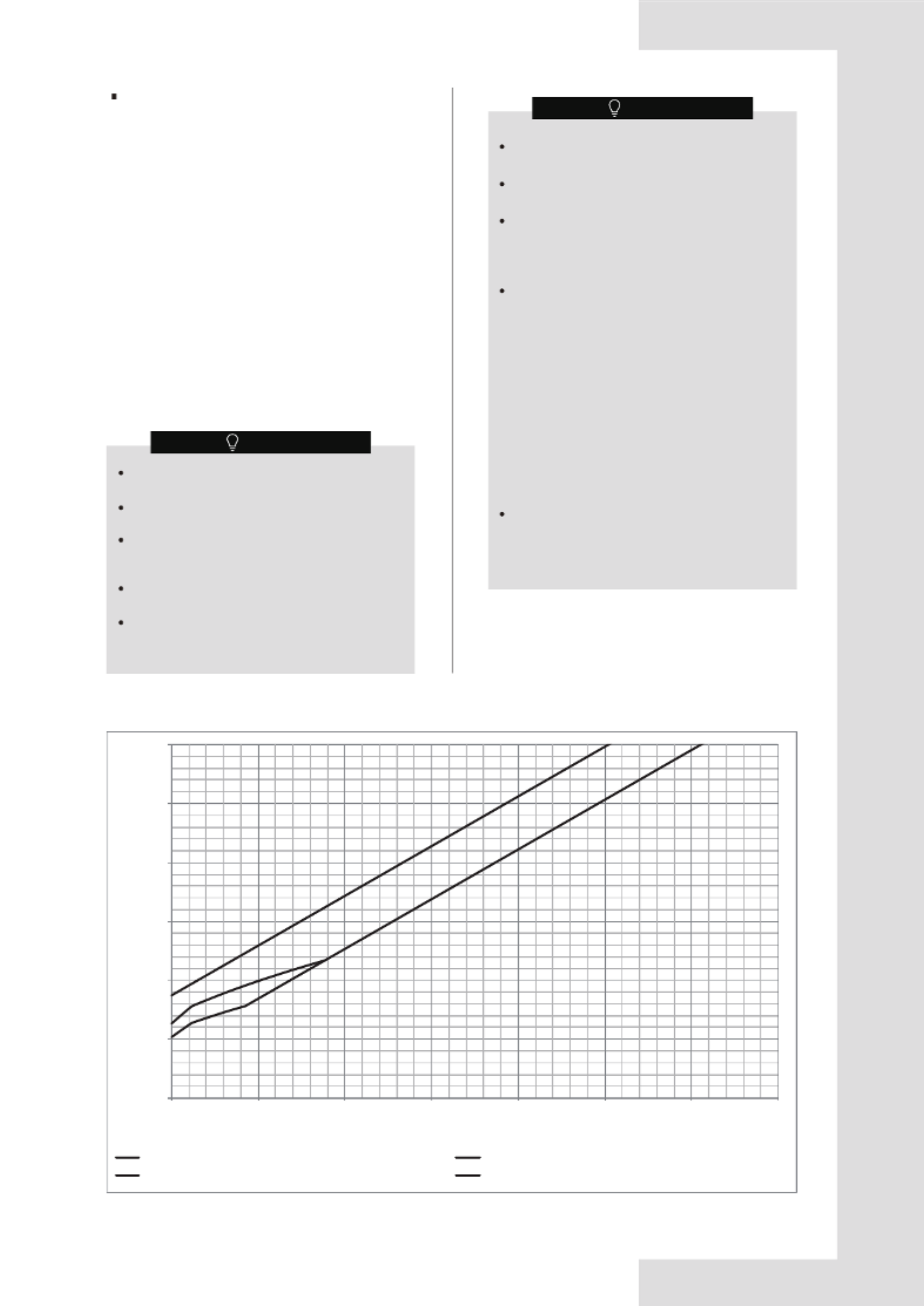
Similarly, the total amount of refrigerant in the system
shall be less than or equal to the maximum refrigerant
charge. The maximum refrigerant charge depends on
the space of the rooms being served by the system.
As shown above:
1) Curve a) is refrigerant charge limitation for the indoor (
unit installation height between 1.8 m and 2.2 m.
2) Curve b) is refrigerant charge limitation for the indoor (
unit installation height not less than 2.2 m.
4 2.048/2.503 23 4.911/6.003 42 6.637/7.956
5 2.29/2.798 24 5.017/6.132 43 6.715/7.956
6 2.508/3.066 25 5.12/6.258 44 6.793/7.956
7 2.709/3.311 26 5.222/6.382 45 6.87/7.956
8 2.896/3.54 27 5.321/6.504 46 6.946/7.956
9 3.072/3.755 28 5.419/6.623 47 7.021/7.956
10 3.238/3.958 29 5.515/6.74 48 7.095/7.956
11 3.396/4.151 30 5.609/6.856 49 7.169/7.956
12 3.547/4.336 31 5.702/6.969 50 7.241/7.956
13 3.692/4.513 32 5.793/7.08 51 7.313/7.956
14 3.832/4.683 33 5.883/7.19 52 7.385/7.956
15 3.966/4.847 34 5.971/7.298 53 7.455/7.956
16 4.096/5.006 35 6.058/7.405 54 7.525/7.956
17 4.222/5.161 36 6.144/7.51 55 7.595/7.956
18 4.345/5.31 37 6.229/7.614 56 7.664/7.956
19 4.464/5.456 38 6.313/7.716 57 7.732/7.956
20 4.58/5.597 39 6.395/7.817 58 7.799/7.956
21 4.693/5.736 40 6.477/7.916 59 7.866/7.956
22 4.803/5.871 41 6.557/7.956 60 7.933/7.956
≥ 61 7.956/7.956
Amin/m2Mmax/kg--(a)/(b) Amin/m2Mmax/kg--(a)/(b) Amin/m2Mmax/kg--(a)/(b)
(a): The IDU installation height between 1.8 m and 2.2 m
(b): The IDU installation height not less than 2.2 m
NOTE
NOTE
NOTE
CAUTION
12
0.00
2.00
4.00
6.00
8.00
10.00
12.00
5 10 15 20 25 30 35 40
(b)
(a)
(d)
(c)
Figure 1-4
For 8-10 kW
Only the factory refrigerant shut-off device can be
used.
The refrigerant shut-off device shall be located
outside.
The refrigerant shut-off device shall only be
installed on the main pipe and is close to the first
branch joint.
The refrigerant shut-off device is not allowed for
series or parallel connections.
The refrigerant shut-off device shall be positioned
to enable access for maintenance by an
authorized person.
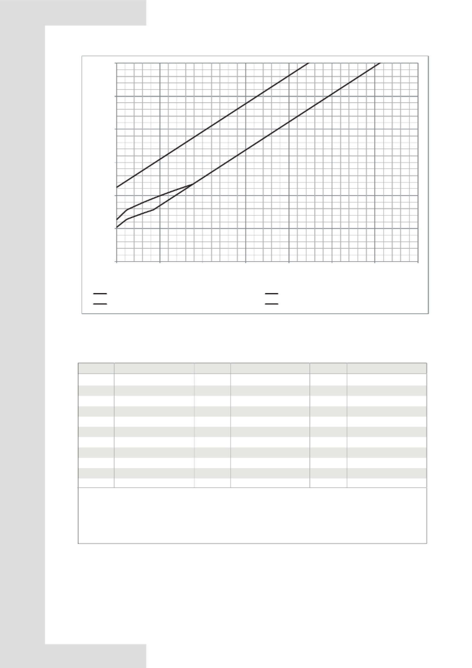
Condition B. With additional measure
If the system is equipped with a factory refrigerant
shut-off device on the outdoor unit main pipe and an
alarm device connected to the indoor unit, further rules
regarding refrigerant charge and room area can be
followed. Figure 1-4 and Table 1-4 is suitable for 8-10
kW and Figure 1-5 and Table 1-5 is suitable for
12-18kW.
The alarm device shall be turned on by the
signal from the refrigerant leakage sensor.
The alarm device shall also alert an authorized
person to take appropriate action.
The alarm device shall provide both audible
and visual warnings, such as by a loud (15 dBA
above the background noise level) buzzer and
a flashing light.
At least one alarm device shall be installed
inside each occupied space. For the occupancy
listed below, the alarm system shall also warn
at a supervised location, such as the night
porter’s location, as well as the occupied
space.
Rooms, parts of buildings, buildings where
• sleeping facilities are provided,
• people are restricted in their movement,
• an uncontrolled number of people are
present, or
• to which any person has access without
being personally acquainted with the
necessary safety precautions.
In cases where the alarm device is installed,
the power source of the alarm system shall be
from a power source independent of the
refrigerating systems which the alarm system is
protecting.
(a) Installation height 1 (on the lowest underground floor & A<14 m2)
(c) In lowest underground floor (A≥14 m2)
(b) Installation height 2 (on the lowest underground floor & A<14 m
2)
(d) Not in lowest underground floor
Maximum refrigerant charge (Mmax/kg)
Minimum room area (Amin/m2)
NOTE
NOTE
1) Curve (a) is the refrigerant charge limitation for the
indoor unit installation height between 1.8 m and
2.2 m while A is < 14 m
2 on the lowest underground
floor.
2) Curve (b) is the refrigerant charge limitation for the
indoor unit installation height not less than 2.2 m
while A is < 14 m
2 on the lowest underground floor.
3) Curve (c) is the refrigerant charge limitation for the
smallest room on the lowest underground floor
while A is ≥ 14 m2.
4) Curve (d) is the refrigerant charge limitation for the
smallest room not on the lowest underground floor.
13
0.00
2.00
4.00
6.00
8.00
10.00
12.00
5 10 15 20 25 30 35 40
(b)
(a)
(d)
(c)
Figure 1-5
For 12-18 kW (Single-phase & three-phase)
For 8-10 kW Table 1-4
(a) Installation height 1 (on the lowest underground floor & A<14 m
2)
(c) On the lowest underground floor (A≥14 m
2)
(b) Installation height 2 (on the lowest underground floor & A<14 m
2)
(d) Not on the lowest underground floor
Maximum refrigerant charge (Mmax/kg)
Minimum room area (Amin/m
2)
Amin/m2Mmax/kg--(a)/(b)/(c)/(d) Mmax/kg--(a)/(b)/(c)/(d) Mmax/kg--(a)/(b)/(c)/(d)
Amin/m2Amin/m2
(a): The IDU installation height is between 1.8 m and 2.2 m while A is <14 m
2 and on the lowest underground floor
(b): The IDU installation height is not less than 2.2 m while A is <14 m
2 and on the lowest underground floor
(c): The refrigerant charge limitation is on the lowest underground floor while A is ≥14 m
2.
(d): The refrigerant charge limitation is not on the lowest underground floor.
4 15 26
5 16 27
6 17 28
7 18 29
8 19 30
9 20 31
10 21 32
11 22 33
12 23 34
13 24 35
≥ 3614 25
1.657/2.026/-/3.15 -/-/5.065/6.865 -/-/8.78/10.58
2.072/2.532/-/3.488 -/-/5.403/7.203 -/-/9.117/10.917
2.486/3.039/-/3.826 -/-/5.74/7.54 -/-/9.455/11.255
2.72/3.325/-/4.163 -/-/6.078/7.878 -/-/9.793/11.593
2.908/3.554/-/4.501 -/-/6.416/8.216 -/-/10.131/11.931
3.085/3.77/-/4.839 -/-/6.754/8.554 -/-/10.468/12
3.377/3.974/-/5.177 -/-/7.091/8.891 -/-/10.806/12
3.714/4.168/-/5.514 -/-/7.429/9.229 -/-/11.144/12
4.052/4.353/-/5.852 -/-/7.767/9.567 -/-/11.481/12
4.39/4.531/-/6.19 -/-/8.104/9.904 -/-/11.819/12
-/-/12/12
-/-/4.727/6.527 -/-/8.442/10.242
14
The application also has a maximum design
refrigerant charge limit of 12 kg, which cannot be
exceeded in any circumstances.
If the system applies to case (d) in Figure 1-4
and Table 1-4 or Figure 1-5 and Table 1-5, the
minimum room area for a 8-10 kW outdoor unit
must not be less than 7 m2 and the minimum
room area for a 12-18 kW outdoor unit must not
be less than 10 m2.
The maximum refrigerant limit described above
applies to unventilated areas. If adding
additional measures, such as areas with
mechanical ventilation, please refer to applicable
legislation for the maximum refrigerant limit.
The maximum
refrigerant
charge has to be
assessed for the room with the smallest room
area in both the lowest underground floor and
the other floors.
And in the lowest underground floor,
the
maximum refrigerant charge is also related to
types of the indoor units, which have different
installation heights.
The lowest maximum allowable charge of all
shall be used.
If the unit is connected via an air duct system to
multiple rooms, the applicable maximum
refrigerant limits are different. Please contact
your installer or dealer for further information
and professional advice.
Determine the charge limit for the refrigerating system
as the smaller of:
1) The maximum refrigerant charge (Mmax) in the
system from
the above room area limitations
.
2) The maximum refrigerant charge (Mmax) with air
duct system or
additional measures, such as areas with
mechanical ventilation.
3) 12 kg from the limit of the application.
The refrigerant leakage sensor can only use the
factory model or the specified model indicated
in the corresponding manual.
The R32 refrigerant leakage sensor must be
used to activate the refrigerant shut-off device,
the alarm device, incorporated circulation airflow
or other emergency controls, which shall give an
electrical signal at a predetermined alarm set
point in response to leaked refrigerant.
The location of leakage sensors shall be chosen
in relation to the refrigerant and they shall be
located where leaked refrigerant will
concentrate. Please refer to the indoor unit
installation manual for specific requirements.
The installation of the refrigerant leakage sensor
shall allow access for checking, repair or
replacement by an authorized person.
The refrigerant leakage sensor shall be installed
so its function can be verified easily.
The refrigerant leakage sensor shall be
protected to prevent tampering or unauthorized
resetting of the pre-set value.
To be effective, the refrigerant leakage sensor
must be electrically powered at all times after
installation, other than when servicing.
For 12-18 kW (Single-phase & three-phase) Table1-5
Amin/m2Mmax/kg--(a)/(b)/(c)/(d) Mmax/kg--(a)/(b)/(c)/(d) Mmax/kg--(a)/(b)/(c)/(d)
Amin/m2Amin/m2
(a): The IDU installation height is between 1.8 m and 2.2 m while A is <14m
2 and on the lowest underground floor
(b): The IDU installation height is not less than 2.2 m while A is <14m
2 and on the lowest underground floor
(c): The refrigerant charge limitation is on the lowest underground floor while A is ≥14m
2.
(d): The refrigerant charge limitation is not on the lowest underground floor.
4 15 26
5 16 27
6 17 28
7 18 29
8 19 30
9 20 31
10 21 32
11 22 33
12 23 34
13 24 35
14 25
2.657/2.026/-/4.15 -/-/5.065/7.865 -/-/8.78/11.58
2.072/2.532/-/4.488 -/-/5.403/8.203 -/-/9.117/11.917
2.486/3.039/-/4.826 -/-/5.74/8.54 -/-/9.455/12
2.72/3.325/-/5.163 -/-/6.078/8.878 -/-/9.793/12
2.908/3.554/-/5.501 -/-/6.416/9.216 -/-/10.131/12
3.085/3.77/-/5.839 -/-/6.754/9.554 -/-/10.468/12
3.377/3.974/-/6.177 -/-/7.091/9.891 -/-/10.806/12
3.714/4.168/-/6.514 -/-/7.429/10.229 -/-/11.144/12
4.052/4.353/-/6.852 -/-/7.767/10.567 -/-/11.481/12
4.39/4.531/-/7.19 -/-/8.104/10.904 -/-/11.819/12
≥36 -/-/12/12-/-/4.727/7.527 -/-/8.442/11.242
NOTE
NOTE
NOTE
CAUTION
CAUTION
15
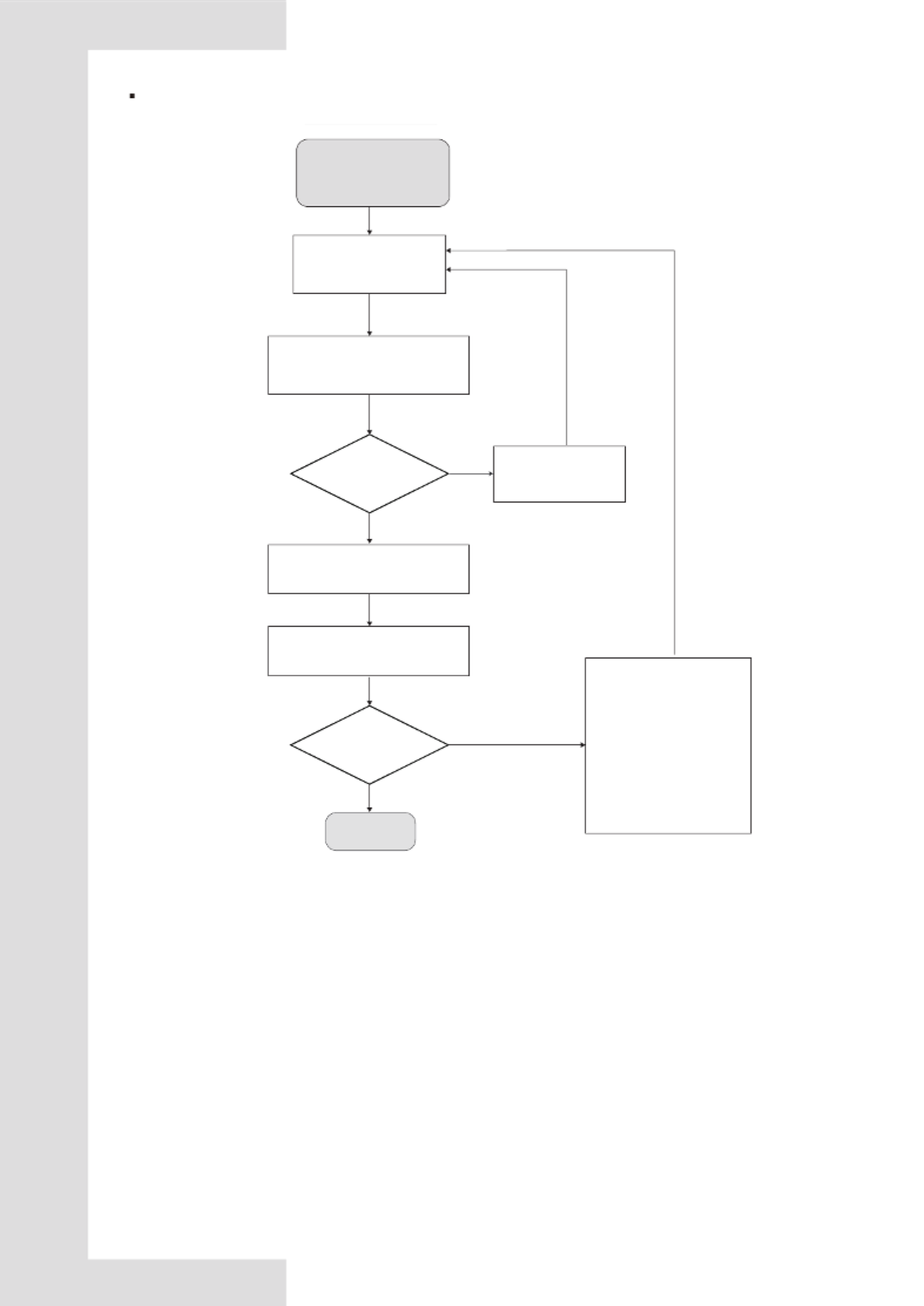
Installation scheme flow chart
Determine the room size
and the refrigerant
system configuration
Determine the strategy of the
refrigerant charge and room area
limitations following section 1.3.1
Decrease piping
length by changing
layout.
Yes
No
Check if the area of the
smallest room meets
the requirements
Calculate the total refrigerant
charging amount (Mc) according to
section 5.8.1
Check the corresponding table to
get the maximum refrigerant
charge (Mmax)
Yes
1.Select the Indoor unit with
a larger airflow rate.
2.Decrease piping length by
changing layout.
3.Increase the smallest
room area.
4.Change the strategy as
described in section 1.3.1.
5. Add additional measures
as described in applicable
legislation.
No
OK
Mc
≤12 kg?
Mc
≤Mmax
16
NOTE
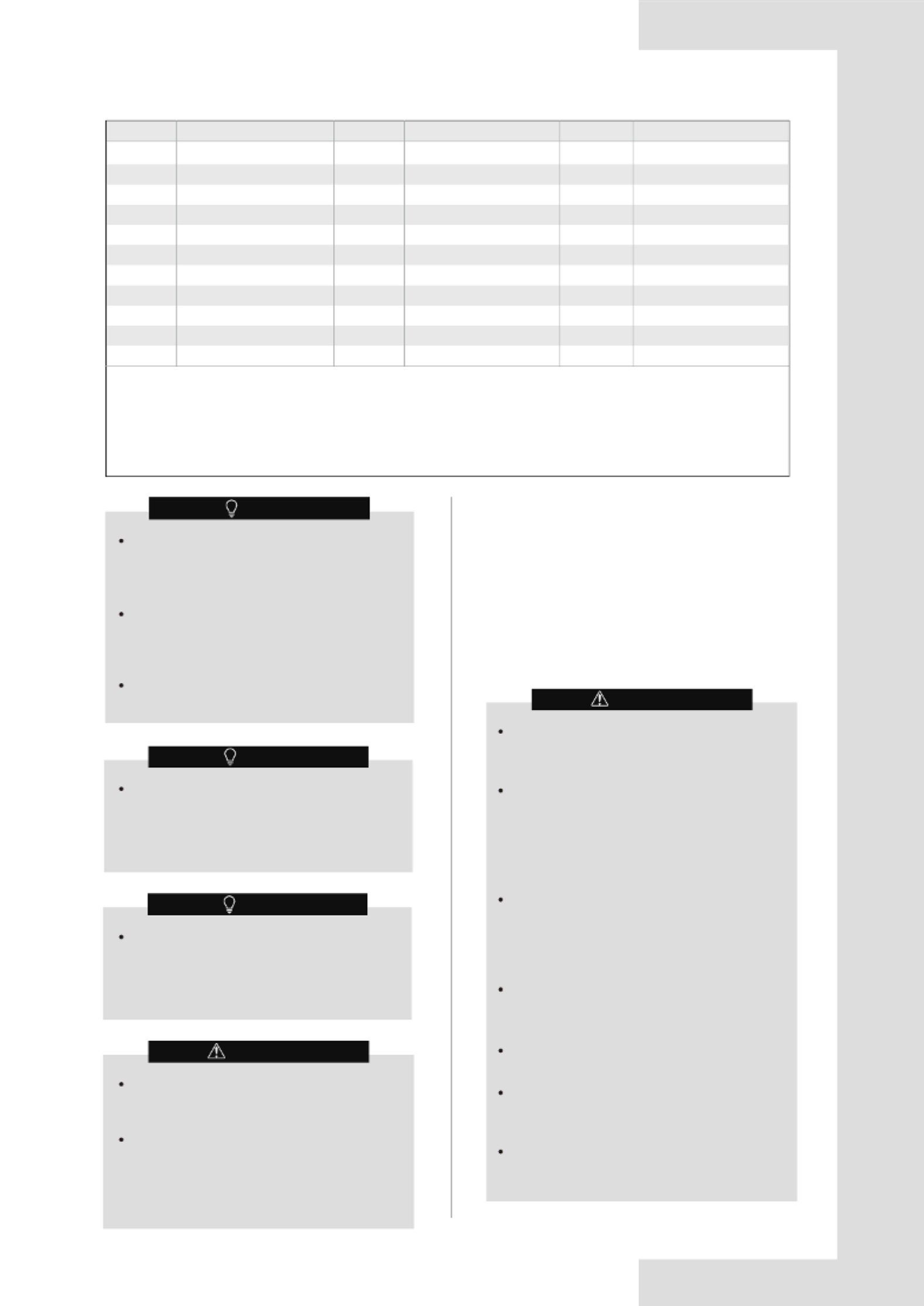
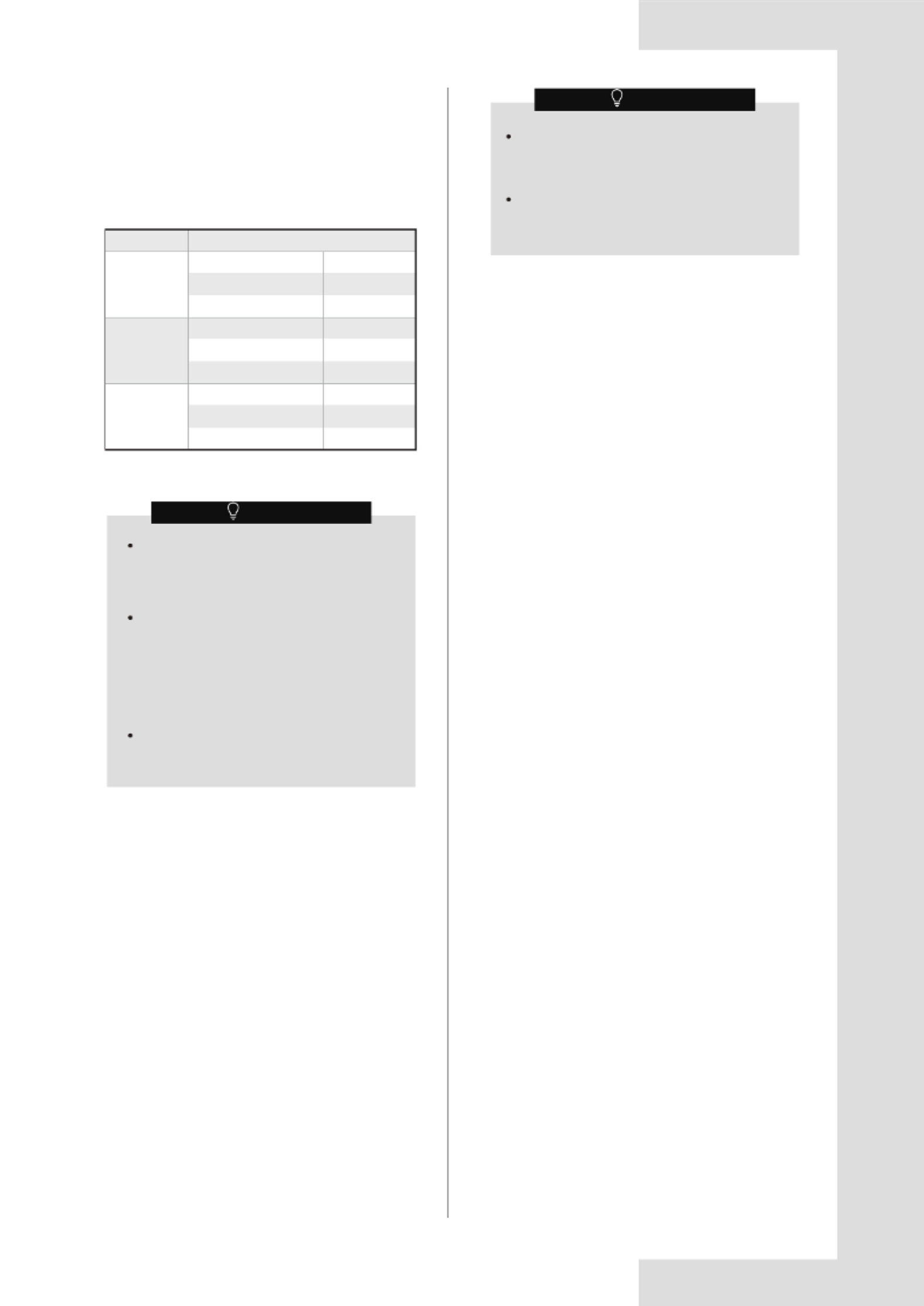
2. OPERATIONS
Use the system in the following temperatures to
ensure safe and effective operation. The Operating
range for the air conditioner is shown in Table 2-1.
Table 2-1
2 Operating Range.1
Cooling
Heating
Dehumidification
Outdoor temperature /DB
Indoor temperature /DB
Indoor temperature /WB
Outdoor temperature /DB
Indoor temperature /DB
Outdoor temperature /WB
Model
-15 °C to 52 °C
8/10/12/14/16/18 kW
16 °C to 30 °C
13 °C to 23 °C
Outdoor temperature /DB
Indoor temperature /DB
Indoor temperature /WB
-15 °C to 52 °C
12 °C to 30 °C
9 °C to 23 °C
-20 °C to 30 °C
-20 °C to 16.5 °C
16 °C to 30 °C
2.2 Operation and Performance
2.2.1 Operating System
Run
2.2.2 Cooling and heating operations
The indoor units in the air conditioner can be controlled
separately, but the indoor units in the same system
cannot operate in the heating and cooling modes at the
same time.
When the cooling and heating operation conflict with
each other, the indoor units which are running in cooling
or fan mode will stop and will display the message
standby or no priority on the control panel. Those indoor
units which are running on heating mode will run
continuously.
If the air conditioner administrator has set the running
mode, then the air conditioner cannot run in any mode
other than the mode presented. Standby or no priority
will be displayed on the control panel.
Press the "switch" button on the controller.
Result: The running light turns on and the system starts
to run.
Stop
Press the "switch" button on the controller again.
Result: The running light is now off, and the system
stops running.
Adjust
Refer to the controller user manual for information about
how to set the required temperature, fan speed and air
flow direction.
Repeatedly press the mode selector on the controller to
select the required operation mode.
If the above operating conditions cannot be
met, the safety protection function may be
triggered and the air conditioner may
malfunction.
When the unit operates in "cooling" mode in a
relatively humid environment (relative
humidity higher than 80%), condensation
may occur on the surface of the IDU and
water may drip. In this case, turn the wind
deflector to the maximum air outlet position
and set the fan speed to "High".
Outdoor operating temperature under -5
°C
in
"cooling" mode, the startup capacity of IDUs
must meet at least 30% of ODU capacity.
NOTE
To protect this unit, please turn on the main
power supply 12 hours before you start to
operate this unit.
Once the unit has stopped running, do not
disconnect the power immediately. Wait for at
least 10 minutes.
2.2.3 Features of heating operation
While heating, as the outdoor temperature decreases,
frost may form on the heat exchanger in the outdoor
unit, making it more difficult for the heat exchanger to
heat up the air. The heating capacity will decrease, and
the system will need to be defrosted in order to provide
sufficient heat to the indoor unit. At this point, the control
panel of the indoor unit will show that a defrost
operation is occurring.
Once the unit starts, it takes some time for the room
temperature to rise, as the unit uses a hot air circulation
system to heat the room.
The indoor fan motor will automatically stop running so
as to prevent cold air from coming out of the indoor unit
when the heating operation starts. This process will take
some time, which depends on the indoor and outdoor
temperature. This is not a malfunction.
When there is a drop in the external temperature, the
heating capacity decreases. If this happens, please use
other heating equipment and units at the same time.
(Make sure the room is well ventilated if you are using
equipment that produces fire.) Do not place any
equipment that may produce a fire where the air outlets
of the unit are or below the unit itself.
And need to perform the following operations to prevent
the heating capacity from dropping or prevent cold air
from coming out of the system.
About heating capacity
Defrost operation
Produktspecifikationer
| Varumärke: | Midea |
| Kategori: | Värmepump |
| Modell: | MV8M-160WV2RN8 |
Behöver du hjälp?
Om du behöver hjälp med Midea MV8M-160WV2RN8 ställ en fråga nedan och andra användare kommer att svara dig
Värmepump Midea Manualer

27 Februari 2025
27 Februari 2025
9 Februari 2025
4 Januari 2025
4 Januari 2025
4 Januari 2025
Värmepump Manualer
- Värmepump Electrolux
- Värmepump Samsung
- Värmepump LG
- Värmepump Bosch
- Värmepump AEG
- Värmepump Grundig
- Värmepump Junkers
- Värmepump Miele
- Värmepump Nefit
- Värmepump Remeha
- Värmepump Siemens
- Värmepump Vaillant
- Värmepump Argo
- Värmepump Arcelik
- Värmepump Artel
- Värmepump Fisher And Paykel
- Värmepump Hisense
- Värmepump Westinghouse
- Värmepump Hotpoint
- Värmepump De Dietrich
- Värmepump Blaupunkt
- Värmepump Balay
- Värmepump Stiebel Eltron
- Värmepump Mitsubishi
- Värmepump Elco
- Värmepump Dimplex
- Värmepump Orima
- Värmepump Nibe
- Värmepump Ferroli
- Värmepump Fujitsu
- Värmepump Viessmann
- Värmepump Wilfa
- Värmepump Carrier
- Värmepump Olimpia Splendid
- Värmepump Itho-Daalderop
- Värmepump Danfoss
- Värmepump Qlima
- Värmepump Worcester
- Värmepump Atlantic
- Värmepump Tesy
- Värmepump AWB
- Värmepump Vivax
- Värmepump Maxicool
- Värmepump Astralpool
- Värmepump Baxi
- Värmepump Weishaupt
- Värmepump Hydro-Pro
- Värmepump Wita
- Värmepump Calorex
- Värmepump Fairland
- Värmepump Thermor
- Värmepump Armstrong
- Värmepump Flojet
- Värmepump Harmopool
- Värmepump JANDY
- Värmepump MRCOOL
- Värmepump Grundfos
- Värmepump Kospel
- Värmepump Wilo
- Värmepump Waterco
- Värmepump Comfortpool
Nyaste Värmepump Manualer
29 Mars 2025
14 Mars 2025
14 Mars 2025
10 Mars 2025
7 Mars 2025
6 Februari 2025
6 Februari 2025
3 Februari 2025
31 Januari 2025
30 Januari 2025