Motu 896Mk3 Hybrid Bruksanvisning
Motu
DJ-utrustning
896Mk3 Hybrid
Läs nedan 📖 manual på svenska för Motu 896Mk3 Hybrid (134 sidor) i kategorin DJ-utrustning. Denna guide var användbar för 12 personer och betygsatt med 4.5 stjärnor i genomsnitt av 2 användare
Sida 1/134

™
MOTU 896mk3 Hybrid
User Guide for Windows
1280 Massachusetts Avenue
Cambridge, MA 02138
Business voice: (617) 576-2760
Business fax: (617) 576-3609
Web site: www.motu.com
Tech support: www.motu.com/support

SAFETY PRECAUTIONS AND ELECTRICAL REQUIREMENTS
CAUTION! READ THIS SAFETY GUIDE BEFORE YOU BEGIN INSTALLATION OR OPERATION. FAILURE TO COMPLY WITH SAFETY INSTRUCTIONS
COULD RESULT IN BODILY INJURY OR EQUIPMENT DAMAGE.
HAZARDOUS VOLAGES: CONTACT MAY CAUSE ELECTRIC SHOCK OR BURN. TURN OFF UNIT BEFORE SERVICING.
WARNING: TO REDUCE THE RISK OF FIRE OR ELECTRICAL SHOCK, DO NOT EXPOSE THIS APPLIANCE TO RAIN OR OTHER MOISTURE.
CAUTION: TO REDUCE THE RISK OF ELECTRICAL SHOCK, DO NOT REMOVE COVER. NO USER-SERVICEABLE PARTS INSIDE. REFER SERVICING TO
QUALIFIED SERVICE PERSONNEL.
WARNING: DO NOT PERMIT FINGERS TO TOUCH THE TERMINALS OF PLUGS WHEN INSTALLING OR REMOVING THE PLUG TO OR FROM THE OUTLET.
WARNING: IF NOT PROPERLY GROUNDED THE MOTU 896mk3 COULD CAUSE AN ELECTRICAL SHOCK.
The MOTU 896mk3 is equipped with a three-conductor cord and grounding type plug which has a grounding prong, approved by Underwriters' Laboratories and the Canadian Standards Association.
This plug requires a mating three-conductor grounded type outlet as shown in Figure A below. If the outlet you are planning to use for the MOTU 896mk3 is of the two prong type, DO NOT REMOVE
OR ALTER THE GROUNDING PRONG IN ANY MANNER. Use an adapter as shown below and always connect the grounding lug to a known ground. It is recommended that you have a qualified
electrician replace the TWO prong outlet with a properly grounded THREE prong outlet. An adapter as illustrated below in Figure B is available for connecting plugs to two-prong receptacles.
WARNING: THE GREEN GROUNDING LUG EXTENDING FROM THE ADAPTER MUST BE CONNECTED TO A PERMANENT GROUND SUCH AS TO A
PROPERLY GROUNDED OUTLET BOX. NOT ALL OUTLET BOXES ARE PROPERLY GROUNDED.
If you are not sure that your outlet box is properly grounded, have it checked by a qualified electrician. NOTE: The adapter illustrated is for use only if you already have a properly grounded two-prong
receptacle. Adapter is not allowed in Canada by the Canadian Electrical Code. Use only three wire extension cords which have three-prong grounding type plugs and three-prong receptacles which
will accept the MOTU 896mk3 plug.
IMPORTANT SAFEGUARDS
1. Read these instructions. All the safety and operating instructions should be read before operating the 896mk3.
2. Keep these instructions. These safety instructions and the 896mk3 owner’s manual should be retained for future reference.
3. Heed all warnings. All warnings on the 896mk3 and in the owner’s manual should be adhered to.
4. Follow all Instructions. All operating and use instructions should be followed.
5. Do not use the 896mk3 near water.
6. Cleaning - Unplug the 896mk3 from the computer and clean only with a dry cloth. Do not use liquid or aerosol cleaners.
7. Ventilation - Do not block any ventilation openings. Install in accordance with the manufacturer’s instructions.
8. Heat - Do not install the 896mk3 near any heat sources such as radiators, heat registers, stoves, or another apparatus (including an amplifier) that produces heat.
9. Overloading - Do not overload wall outlets and extension cords as this can result in a risk of fire or electrical shock.
10. Grounding - Do not defeat the safety purpose of the polarized or grounding-type plug. A polarized plug has two blades with one wider than the other. A grounding-type plug has two blades and a third grounding prong. The wide blade
or the third prong are provided for your safety. If the provided plug does not fit into your outlet, consult and electrician for replacement of the obsolete outlet.
11. Power cord - Protect the 896mk3 power cord from being walked on or pinched by items placed upon or against them. Pay particular attention to cords and plugs, convenience receptacles, and the point where they exit from the unit.
12. Power switch - Install the 896mk3 so that the power switch can be accessed and operated at all times.
13. Disconnect - The main plug is considered to be the disconnect device for the 896mk3 and shall remain readily operable.
14. Accessories - Only use attachments/accessories specified by the manufacturer.
15. Placement - Use only with the cart, stand, tripod, bracket or table specified by the manufacturer, or sold with the 896mk3. When a cart is used, use caution when moving the cart/apparatus combination to avoid injury from tip-over.
16. Surge protection - Unplug the 896mk3 during lightning storms or when unused for long periods of time.
17. Servicing - Refer all servicing to qualified service personnel. Servicing is required when the 896mk3 has been damaged in any way, such as when a power-supply cord or plug is damaged, liquid has been spilled or objects have fallen
into the 896mk3, the 896mk3 has been exposed to rain or moisture, does not operate normally, or has been dropped.
18. Power Sources - Refer to the manufacturer’s operating instructions for power requirements. Be advised that different operating voltages may require the use of a different line cord and/or attachment plug.
19. Installation - Do not install the 896mk3 in an unventilated rack, or directly above heat-producing equipment such as power amplifiers. Observe the maximum ambient operating temperature listed below.
20. Power amplifiers- Never attach audio power amplifier outputs directly to any of the unit’s connectors.
21. Replacement Parts - When replacement parts are required, be sure the service technician has used replacement parts specified by the manufacturer or have the same characteristics as the original part. Unauthorized substitutions
may result in fire, electric shock or other hazards.
22. Safety Check - Upon completion of any service or repairs to this MOTU 896mk3, ask the service technician to perform safety checks to determine that the product is in safe operating conditions.
ENVIRONMENT
Operating Temperature: 10°C to 40°C (50°F to 104°)
TO REDUCE THE RISK OF ELECTRICAL SHOCK OR FIRE
Do not handle the power cord with wet hands. Do not pull on the power cord when disconnecting it from an AC wall outlet. Grasp it by the plug. Do not expose this apparatus to rain or moisture. Do not place objects containing liquids on it.
AC INPUT
100 - 240VAC ~ • 50 / 60Hz • 25 Watts.
3-prong plug
Grounding prong
Properly grounded 3-prong outlet
Grounding lug
Screw
3-prong plug
Adapter
Make sure this is connected to
a known ground.
Two-prong receptacle
Figure A Figure B

III
Contents
Part 1: Getting Started
7Quick Reference: 896mk3 Front Panel
8Quick Reference: 896mk3 Rear Panel
9Quick Reference: MOTU Audio Console
11 About the 896mk3 Hybrid
17 Packing List and System Requirements
19 Installing the 896mk3 Software
21 Installing the 896mk3 Hardware
Part 2: Using the 896mk3 Hybrid
39 MOTU Audio Console
47 Front Panel Operation
57 Configuring Host Audio Software
65 Reducing Monitoring Latency
71 CueMix FX
119 MOTU SMPTE Console
Part 3: Appendices
125 Audio I/O reference
129 Troubleshooting
131 Index

About the Mark of the Unicorn License Agreement and
Limited Warranty on Software
TO PERSONS WHO PURCHASE OR USE THIS PRODUCT: carefully read all the
terms and conditions of the “click-wrap” license agreement presented to you when
you install the software. Using the software or this documentation indicates your
acceptance of the terms and conditions of that license agreement.
Mark of the Unicorn, Inc. (“MOTU”) owns both this program and its documentation.
Both the program and the documentation are protected under applicable copyright,
trademark, and trade-secret laws. Your right to use the program and the
documentation are limited to the terms and conditions described in the license
agreement.
Reminder of the terms of your license
This summary is not your license agreement, just a reminder of its terms. The actual
license can be read and printed by running the installation program for the software.
That license agreement is a contract, and clicking “Accept” binds you and MOTU to
all its terms and conditions. In the event anything contained in this summary is
incomplete or in conflict with the actual click-wrap license agreement, the terms of the
click-wrap agreement prevail.
YOU MAY: (a) use the enclosed program on a single computer; (b) physically transfer
the program from one computer to another provided that the program is used on only
one computer at a time and that you remove any copies of the program from the
computer from which the program is being transferred; (c) make copies of the
program solely for backup purposes. You must reproduce and include the copyright
notice on a label on any backup copy.
YOU MAY NOT: (a) distribute copies of the program or the documentation to others;
(b) rent, lease or grant sublicenses or other rights to the program; (c) provide use of
the program in a computer service business, network, time-sharing, multiple CPU or
multiple user arrangement without the prior written consent of MOTU; (d) translate,
adapt, reverse engineer, decompile, disassemble, or otherwise alter the program or
related documentation without the prior written consent of MOTU.
MOTU warrants to the original licensee that the disk(s) on which the program is
recorded be free from defects in materials and workmanship under normal use for a
period of ninety (90) days from the date of purchase as evidenced by a copy of your
receipt. If failure of the disk has resulted from accident, abuse or misapplication of the
product, then MOTU shall have no responsibility to replace the disk(s) under this
Limited Warranty.
THIS LIMITED WARRANTY AND RIGHT OF REPLACEMENT IS IN LIEU OF,
AND YOU HEREBY WAIVE, ANY AND ALL OTHER WARRANTIES, BOTH
EXPRESS AND IMPLIED, INCLUDING BUT NOT LIMITED TO WARRANTIES
OF MERCHANTABILITY AND FITNESS FOR A PARTICULAR PURPOSE. THE
LIABILITY OF MOTU PURSUANT TO THIS LIMITED WARRANTY SHALL BE
LIMITED TO THE REPLACEMENT OF THE DEFECTIVE DISK(S), AND IN NO
EVENT SHALL MOTU OR ITS SUPPLIERS, LICENSORS, OR AFFILIATES BE
LIABLE FOR INCIDENTAL OR CONSEQUENTIAL DAMAGES, INCLUDING
BUT NOT LIMITED TO LOSS OF USE, LOSS OF PROFITS, LOSS OF DATA OR
DATA BEING RENDERED INACCURATE, OR LOSSES SUSTAINED BY THIRD
PARTIES EVEN IF MOTU HAS BEEN ADVISED OF THE POSSIBILITY OF
SUCH DAMAGES. THIS WARRANTY GIVES YOU SPECIFIC LEGAL RIGHTS
WHICH MAY VARY FROM STATE TO STATE. SOME STATES DO NOT ALLOW
THE LIMITATION OR EXCLUSION OF LIABILITY FOR CONSEQUENTIAL
DAMAGES, SO THE ABOVE LIMITATION MAY NOT APPLY TO YOU.
Update Policy
In order to be eligible to obtain updates of the program, you must complete and return
the attached Mark of the Unicorn Purchaser Registration Card to MOTU.
Copyright Notice
Copyright © 2011, 2010, 2009, 2008, 2007, 2006, 2005, 2004, 2003 by Mark of the
Unicorn, Inc. All rights reserved. No part of this publication may be reproduced,
transmitted, transcribed, stored in a retrieval system, or translated into any human or
computer language, in any form or by any means whatsoever, without express
written permission of Mark of the Unicorn, Inc., 1280 Massachusetts Avenue,
Cambridge, MA, 02138, U.S.A.
Limited Warranty on Hardware
Mark of the Unicorn, Inc. and S&S Research (“MOTU/S&S”) warrant this equipment
against defects in materials and workmanship for a period of TWO (2) YEARS from
the date of original retail purchase. This warranty applies only to hardware products;
MOTU software is licensed and warranted pursuant to separate written statements.
If you discover a defect, first write or call Mark of the Unicorn at (617) 576-2760 to
obtain a Return Merchandise Authorization Number. No service will be performed on
any product returned without prior authorization. MOTU will, at its option, repair or
replace the product at no charge to you, provided you return it during the warranty
period, with transportation charges prepaid, to Mark of the Unicorn, Inc., 1280
Massachusetts Avenue, MA 02138. You must use the product’s original packing
material for in shipment, and insure the shipment for the value of the product. Please
include your name, address, telephone number, a description of the problem, and
the original, dated bill of sale with the returned unit and print the Return Merchandise
Authorization Number on the outside of the box below the shipping address.
This warranty does not apply if the equipment has been damaged by accident,
abuse, misuse, or misapplication; has been modified without the written permission
of MOTU, or if the product serial number has been removed or defaced.
ALL IMPLIED WARRANTIES, INCLUDING IMPLIED WARRANTIES OF
MERCHANTABILITY AND FITNESS FOR A PARTICULAR PURPOSE, ARE
LIMITED IN DURATION TO TWO (2) YEARS FROM THE DATE OF THE
ORIGINAL RETAIL PURCHASE OF THIS PRODUCT.
THE WARRANTY AND REMEDIES SET FORTH ABOVE ARE EXCLUSIVE
AND IN LIEU OF ALL OTHERS, ORAL OR WRITTEN, EXPRESS OR IMPLIED.
No MOTU/S&S dealer, agent, or employee is authorized to make any modification,
extension, or addition to this warranty.
MOTU/S&S ARE NOT RESPONSIBLE FOR SPECIAL, INCIDENTAL, OR
CONSEQUENTIAL DAMAGES RESULTING FROM ANY BREACH OF
WARRANTY, OR UNDER ANY LEGAL THEORY, INCLUDING LOST PROFITS,
DOWNTIME, GOODWILL, DAMAGE OR REPLACEMENT OF EQUIPMENT
AND PROPERTY AND COST OF RECOVERING REPROGRAMMING, OR
REPRODUCING ANY PROGRAM OR DATA STORED IN OR USED WITH
MOTU/S&S PRODUCTS.
Some states do not allow the exclusion or limitation of implied warranties or liability for
incidental or consequential damages, so the above limitation or exclusion may not
apply to you. This warranty gives you specific legal rights, and you may have other
rights which vary from state to state.
MOTU, AudioDesk, Mark of the Unicorn and the unicorn silhouette logo are
trademarks of Mark of the Unicorn, Inc.
This equipment has been type tested and found to comply with the limits for a class B digital device,
pursuant to Part 15 of the FCC Rules. These limits are designed to provide reasonable protection
against harmful interference in a residential installation. This equipment generates, uses, and can
radiate radio frequency energy and, if not installed and used in accordance with the instruction manual,
may cause harmful interference to radio communications. However, there is no guarantee that
interference will not occur in a particular installation. If this equipment does cause interference to radio
or television equipment reception, which can be determined by turning the equipment off and on, the
user is encouraged to try to correct the interference by any combination of the following measures:
• Relocate or reorient the receiving antenna
• Increase the separation between the equipment and the receiver
• Plug the equipment into an outlet on a circuit different from that to which the receiver is connected
If necessary, you can consult a dealer or experienced radio/television technician for additional
assistance.
PLEASE NOTE: only equipment certified to comply with Class B (computer input/output devices,
terminals, printers, etc.) should be attached to this equipment, and it must have shielded interface
cables in order to comply with the Class B FCC limits on RF emissions.
WARNING: changes or modifications to this unit not expressly approved by the party
responsible for compliance could void the user's authority to operate the equipment.

Part 1
Getting Started


Quick Reference: 896mk3 Rear Panel
1. These AES/EBU connectors can handle any supported
sample rate up to 96 kHz, and they are also equipped
with a sample rate converter so you can input or output
at a different rate than the 896mk3. For details, see
“Syncing AES/EBU devices” on page 30. At the 4x
sample rates, (176.4 and 192kHz), AES/EBU is disabled.
2. These two XLR jacks serve as the MOTU 896mk3’s main
analog outputs. You can connect them to a set of
powered studio monitors and then control the volume
from the front panel MASTER VOL knob. These jacks are
always mirrored by the MAIN OUT headphone jack on
the front panel.
To hear disk tracks in your audio software on these main
outs, assign the disk tracks (and master fader) to these
main outs. Also make sure the Main Out Assign option is
set to Main Out 1-2. See “Main Out Assign” on page 44.
You can also use CueMix FX to monitor live 896mk3
inputs here as well.
3. The 896mk3’s eight analog outputs are XLR connectors
referenced to +19 dBU. They are equipped with 24-bit
D/A converters capable of 192kHz.
4. These XLR/TRS combo jacks accept either a mic cable or
a quarter-inch cable. The XLR jack is equipped with a
mic preamp. 48V phantom power and 20 dB pad can be
applied via the trim knobs on the front panel. The trim
knob provides 53 dB of gain. The quarter-inch jack can
accept a guitar or -10/+4 dB line level input. When
connecting a line level input, be sure to turn off
phantom power first, and engage the -20 dB pad.
5. Connect the 896mk3 to the computer here via either
FireWire or USB2, using the standard 1394 FireWire B or
USB cable provided with your MOTU 896mk3. If you use
FireWire, you can use the extra FireWire port to daisy-
chain up to four MOTU FireWire audio interfaces to a
single FireWire bus, or to connect other FireWire
devices. Keep in mind that the 896mk3 uses more
FireWire bus bandwidth when one or both optical
banks are enabled, or when it operates at higher
sample rates. These operating configurations will limit
the number of devices you can daisy chain on a single
FireWire bus. For details, see “Connecting multiple
MOTU FireWire interfaces” on page 35.
6. These optical digital I/O connectors can be connected
either to an ADAT-compatible “lightpipe” device (such
as a digital mixer) or to a S/PDIF optical (“TOSLINK”)
compatible device, such as an effects processor or DAT
machine. Be sure to set the format in the MOTU Audio
Console software (or using the front panel LCD). (See
“Optical input/output” on page 44 for details.) ADAT
optical supplies eight channels of 24-bit digital
I/O per bank (4 channels per bank at 96kHz). TOSLINK is
stereo at sample rates up to 96 kHz.
One special note: you can choose independent formats
for each bank, A and B, as well as IN and OUT within
each bank. For example, you could choose ADAT for the
optical A IN (for, say, eight channels of input from your
digital mixer) and stereo TOSLINK for the optical A OUT
(for, say, your DAT machine).
7. These jacks provide stereo, 24-bit S/PDIF digital input
and output at all supported sample rates (up to 96 kHz).
8. Use the word clock input and output for digital transfers
with devices that cannot slave to the clock supplied by
their digital I/O connection with the 896mk3.
9. The 896mk3 is equipped with an auto-switching inter-
national power supply.
1 2 3
46789 5

9
Quick Reference:
MOTU Audio Console
Device Setup in Cubase
Choosing a smaller setting here reduces the
delay you may hear when listening to live
input that you are running through effects
plug-ins in your software. But lower settings
also increase the strain on your computer. For
details, see “Samples Per Buffer” on page 42.
Choose the output pair you would like the
main outs to mirror, or choose Main Out 1-2 to
operate them as their own independent pair.
This menu lets you choose what you will
hear from the PHONES jack. To mirror the
main outs, choose Main Out 1-2. Or you can
mirror any other output pair. To hear the
phones as their own independent output,
choose Phones 1-2 (at 44.1 or 48 kHz). At
higher sample rates, the phones must
mirror any other available output pair.)
Uncheck this option if the Windows audio
software you are using with the 896mk3
does not support Windows WaveRT drivers
and instead only supports WDM drivers.
Each optical bank can be configured
independently: ADAT or TOSLINK. Disable
them when not in use to conserve DSP
and FireWire/USB bus bandwidth.
Choose the global sample rate for the
system here.
Provides several options for the 896mk3’s
AES/EBU sample rate conversion. See,
“Syncing AES/EBU devices” on page 30.
Click the tabs to access general MOTU
interface settings or settings specific to the
896mk3 (or other connected interface.)
Determines the clock source for your
896mk3. If you’re just using the analog ins
and outs, set this to ‘Internal’. The other
settings are for digital transfers via AES/
EBU, S/PDIF or optical ports, or for slaving
the 896mk3 to word clock.
Click the 896mk3 tab to access these
settings.
If you have a foot switch connected to the
896mk3, these settings let you map the
foot switch to any computer keyboard key
for both the up and down position. For
details about how to set this up, see
“Enable Pedal” on page 43.
This option should always be left on
(checked). There are only a few rare cases
in which you would want to turn it off. For
details, refer to the MOTU tech support
database at www.motu.com.
How to access these settings
The 896mk3 driver provides a stereo return
back to the computer. This return feeds the
signal on any 896mk3 output pair directly
back to the computer, where you can record,
process, monitor or otherwise use it. This is a
great way to “bounce” full mixes, complete
with live audio routed through the 896mk3
only, back into the computer.
There are several ways to access these settings:
■From the Windows Start menu, choose
Programs>MOTU>MOTU Audio Console.
■From within Cubase, go to the Device Setup
window, click the MOTU Audio ASIO list item and
and click the Control Panel button.
■From within other applications, refer to their
documentation.
If you are running an 896mk3 interface at a
high sample rate (96, 88.2, 176.4 or 192
kHz), this option appears in the interface tab.
It lets you choose a word clock output rate
that either matches the global sample rate
(e.g. 96kHz) or reduces it to the correspond-
ing 1x rate (e.g. 48kHz instead of 192 kHz).
Lets you choose what to monitor with the
896mk3’s programmable front panel
meters.
The Clip Hold Time controls how long the
top-most red LED remains illuminated
after clipping. The Peak Hold Time
controls how long the highest illumi-
nated LED remains lit before going dark.

10

CHAPTER
11
1About the 896mk3 Hybrid
Overview . . . . . . . . . . . . . . . . . . . . . . . . . . . . . . . . . . . . . . . . . . . . 11
The 896mk3 Hybrid rear panel . . . . . . . . . . . . . . . . . . . . . . 12
The 896mk3 Hybrid front panel . . . . . . . . . . . . . . . . . . . . . 14
16-bit and 24-bit recording . . . . . . . . . . . . . . . . . . . . . . . . . . 15
CueMix FX 32-bit floating point mixing and effects. . 15
Included software . . . . . . . . . . . . . . . . . . . . . . . . . . . . . . . . . . . 15
Host audio software . . . . . . . . . . . . . . . . . . . . . . . . . . . . . . . . . 16
OVERVIEW
The 896mk3 Hybrid is a hybrid FireWire USB2
audio interface for Mac and Windows that provides
28 separate inputs and 32 separate outputs (at 44.1
or 48kHz). Both analog and digital I/O are offered
at sample rates up to 96 kHz, and analog recording
and playback is offered at rates up to 192 kHz. All
inputs and outputs can be accessed simultaneously.
The 896mk3 Hybrid consists of a standard 19-inch,
double space, rack-mountable I/O unit that
connects directly to a computer via a standard
FireWire or USB cable.
The 896mk3 offers the following main features:
■Universal computer connectivity via FireWire or
high-speed USB2
■Eight 24-bit XLR analog outputs
■Eight 24-bit analog inputs equipped with
XLR/TRS “combo” jacks
■Eight mic preamps (one on each input)
■Independent 48V phantom power and 20 dB
pad for each mic input
■Independent front-panel Precision Digital
Trim™ for each input
■Two extra XLR analog main outs
■Operation on all analog I/O at standard sample
rates up to 192 kHz
■Two banks of optical digital I/O that provide 16
channels of ADAT optical at 48 kHz, 8 channels of
S/MUX optical I/O at 96 kHz or two banks of
stereo TOSLINK at rates up to 96 kHz
■AES/EBU digital I/O at samples rates up to
96 kHz with sample rate conversion
■RCA S/PDIF at sample rates up to 96 kHz
■Word clock input and output
■On-board SMPTE synchronization via any
analog input and output
■Two FireWire jacks for chaining multiple units
■Foot switch input for hands-free punch-in/out
■Two phone jacks with independent volume
control
■Programmable master volume knob
■CueMix™ FX no-latency mixing, monitoring
and effects processing
■Front-panel LCD programming for the mixer
and all other settings
■Dedicated 10-segment LED level meters for all
eight analog inputs
■Dedicated 10-segment level meters for main outs
■Programmable 10-segment LED level meters
that display levels for any 8-channel input or output
bank, as well as AES/EBU or S/PDIF digital I/O
■Auto-switching international power supply
■Stand-alone operation
■Mac and Windows drivers for multi-channel
operation and across-the-board compatibility with
any audio software on current Mac and Windows
systems

A B O U T T H E 8 9 6 M K 3 H Y B R I D
12
With a variety of I/O formats, mic preamps, no-
latency mixing and processing of live input and
synchronization capabilities, the 896mk3 Hybrid is
a complete, portable “studio in a box” when used
with a Mac or Windows computer.
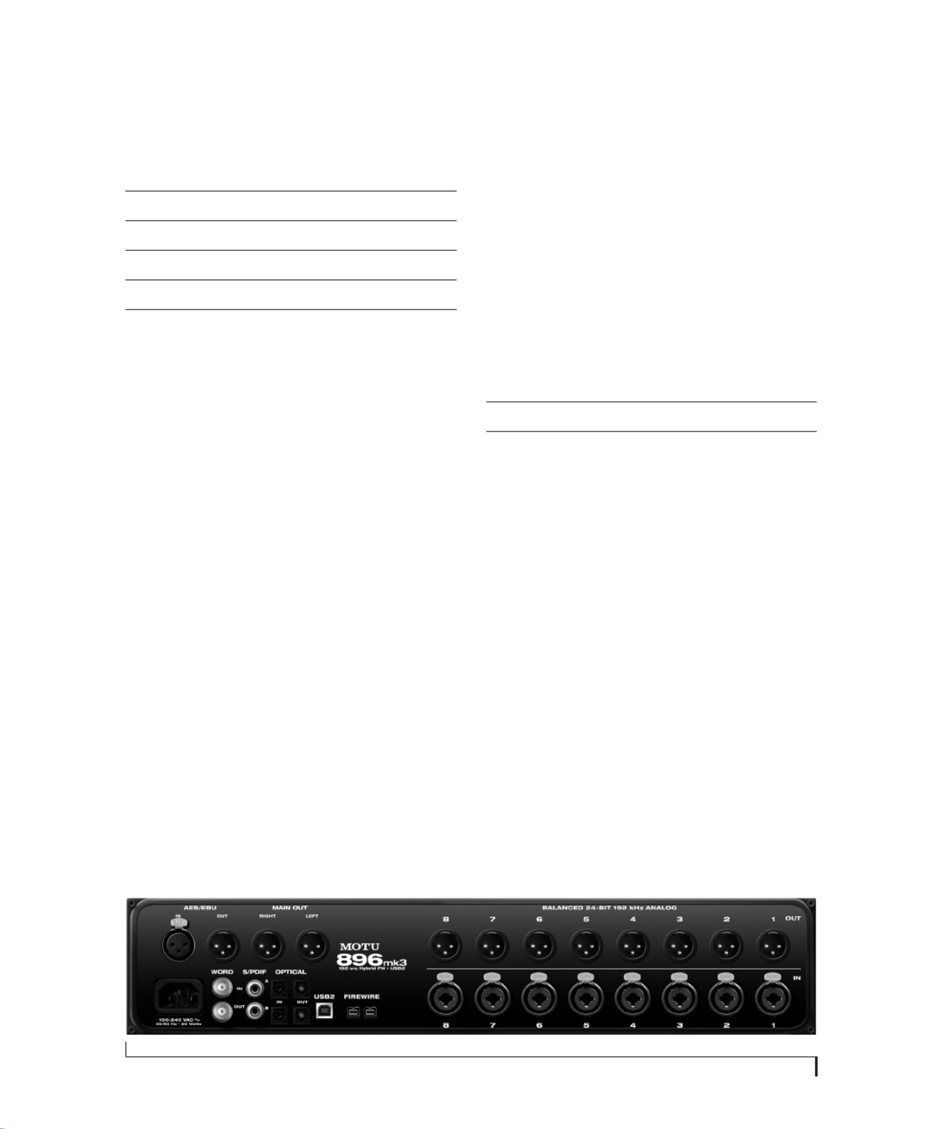
THE 896MK3 HYBRID REAR PANEL
The 896mk3 Hybrid rear panel has the following
connectors:
■Eight 24-bit 192 kHz XLR analog outputs
■Eight 24-bit 192 kHz “combo” (XLR + balanced
quarter-inch) analog inputs, each equipped with a
mic preamp, front-panel 48V phantom power
switch, pad switch, and trim knob
■Two XLR main analog outputs with front-panel
volume knob
■Two sets of optical connectors (in and out),
individually switchable among ADAT optical
“lightpipe”, 96 kHz S/MUX optical or S/PDIF
“TOSLINK”
■AES/EBU input and output
■RCA S/PDIF in/out
■BNC word clock input and output
■Two 1394 FireWire B connectors
■One high-speed USB2 connector
28 inputs and 32 outputs
All 896mk3 inputs and outputs can be used simul-
taneously, for a total of 28 inputs and 32 outputs at
44.1/48kHz:
* The phone jack below the MASTER VOL knob is
hard-wired to (mirrors) the XLR main outs. The
PHONES output can operate as an independent
output pair, or it can mirror any other 896mk3
output pair, such as the main outs.
† The 896mk3 optical connectors support several
standard optical I/O formats, which provide
varying channel counts. See “Optical input/
output” on page 44 for details about optical bank
operation.
With the exception of the phone jack on the front
panel labeled “(MAIN OUT)”, all inputs and
outputs are discrete. For example, using the main
outs does not “steal” an output pair from the bank
of eight XLR analog outputs. The same is true for
the headphone outs.
Analog
All 10 analog inputs and outputs are equipped with
24-bit 192 kHz A/D converters. All audio is carried
to the computer in a 24-bit data stream.
Mic/guitar preamps
All eight analog inputs are equipped with a preamp
on a combo-style connector that accepts either an
XLR or quarter-inch (guitar) plug. Individual 48V
Connection Input Output
24-bit 192kHz XLR analog 8 8
24-bit 192kHz XLR main outputs - stereo
Headphone output* - stereo
ADAT optical digital† 16 16
AES/EBU 24-bit 96kHz digital stereo stereo
RCA S/PDIF 24-bit 96kHz digital stereo stereo
Total 28 32

A B O U T T H E 8 9 6 M K 3 H Y B R I D
13
phantom power and 20 dB pad are supplied by
separate front panel switches for each input. In
addition, each input has its own trim knob.
Precision Digital Trim™
All of the 896mk3’s analog inputs are equipped
with digitally controlled analog trims, adjustable in
approximately 1 dB increments. The mic/
instrument input trims can be adjusted using
front-panel digital rotary encoders that provide
feedback in the front panel LCD with up to 53 dB of
boost. All analog inputs can be trimmed with the
front panel knobs or with the 896mk3’s included
CueMix FX control software for Mac and
Windows. This gives you finely-tuned control of
trim settings for a wide variety of analog inputs for
optimum levels. Different trim configurations can
then be saved as preset configurations for instant
recall.
Analog input overload protection
All eight mic inputs are equipped with V-Limit™,
a hardware limiter that helps prevent digital
clipping from overloaded input signals. With
V-Limit enabled, signals can go above zero dB
(with limiting applied) to as high as +12 dB above
zero with no distortion due to digital clipping.
Additional or alternative protection can be applied
to the mic/guitar inputs by enabling the 896mk3’s
Soft Clip feature, which engages just before
clipping occurs and helps reduce perceptible
distortion.
Main Outs
The main outs are equipped with 24-bit 192kHz
D/A converters and serve as independent outputs
for the computer or for the 896mk3’s on-board
CueMix FX mixes. The main out volume can be
controlled with the front panel volume knob.
Optical
The two optical banks provide 16 channels of
ADAT optical at 44.1 or 48 kHz, 8 channels of
S/MUX optical I/O at 96 kHz or two banks of
stereo TOSLINK at rates up to 96 kHz. The banks
operate independently, including input and output,
allowing you to mix and match any optical formats.
For example, you could receive 4 channels of
96 kHz S/MUX input on Bank A while at the same
time sending 96 kHz stereo optical S/PDIF
(“TOSLINK”) from the Bank A output.
AES/EBU with sample rate conversion
The 896mk3 rear panel provides a standard
AES/EBU digital input and output that supports
digital I/O at 44.1, 48, 88.2 and 96 kHz. In addition,
input or output can be sample-rate converted to
any of these sample rates in situations that call for a
different rate than the 896mk3’s global sample rate.
The AES/EBU jacks are disabled at the 4x sample
rates (176.4 and 192kHz).
S/PDIF
The 896mk3 rear panel provides S/PDIF input and
output in two different formats: RCA “coax” and
optical “TOSLINK”. The RCA jacks are dedicated
to the S/PDIF format. The TOSLINK jacks can be
used for either TOSLINK or ADAT optical, as
discussed earlier.
Word clock
The 896mk3 provides standard word clock that can
slave to any supported sample rate. In addition,
word clock can resolve to and generate “high” and
“low” sample rates. For example, if the 896mk3
global sample rate is set to 96 kHz, the word clock
input can resolve to a “low” rate of 48 kHz.
Similarly, when the 896mk3 is operating at
192 kHz, MOTU Audio Console lets you choose a
word clock output rate of 48 kHz (the Force 44.1/
48kHz setting).

A B O U T T H E 8 9 6 M K 3 H Y B R I D
14
On-board SMPTE synchronization
The 896mk3 can resolve directly to SMPTE time
code via any TRS analog input, without a separate
synchronizer. The 896mk3 can also generate
SMPTE time code via any XLR analog output. The
896mk3 provides a DSP-driven phase-lock engine
with sophisticated filtering that provides fast
lockup times and sub-frame accuracy.
The included MOTU SMPTE Console™ software
provides a complete set of tools for generating and
regenerating SMPTE time code, which allows you
to slave other devices to the computer. Like
CueMix FX, the synchronization features are
cross-platform and compatible with all audio
sequencer software that supports the ASIO2
sample-accurate sync protocol.
Hybrid FireWire/USB2 connectivity
FireWire has long been recognized as a reliable,
high-performance connectivity standard for
professional MOTU audio interfaces. Meanwhile,
high-speed USB2 has also developed into a widely
adopted standard for connecting peripheral
devices to personal computers.
To fully support both formats, the 896mk3 Hybrid
audio interface is equipped with both FireWire B
(400 Mbit/sec) connectors and a high-speed USB2
(480 Mbit/sec) connector, and you can use either
port to connect the 896mk3 to your computer. This
gives you maximum flexibility and compatibility
with today’s ever-expanding universe of Mac and
Windows computers.
THE 896MK3 HYBRID FRONT PANEL
Metering
The front panel of the MOTU 896mk3 displays two
eight-channel banks of 10-segment ladder LEDs.
The left-hand bank always shows the eight analog
inputs. The right-hand bank shows any other bank
you choose with the Meters knob: Analog out,
optical I/O (ADAT or TOSLINK) or digital I/O
(AES/EBU and S/PDIF). A status LED to the right
shows which bank you are currently viewing. You
can also adjust this setting in the MOTU Audio
Console software.
The 896mk3 front panel also displays stereo meters
for the main analog outs.
The Clock lights indicate the global sample rate (as
chosen in the MOTU Audio Console software).
The Rate Convert LEDs indicate if sample rate
conversion is being applied to the AES/EBU input
or output, and if so, the rate being converted to.
Input trim knobs, phantom power & 20 dB Pad
The front-panel input trim knobs provide 53 dB of
boost, -20 dB pad (by pushing the knob), and 48V
phantom power (by holding in the knob) for each
mic input.
Headphone output and main volume control
The 896mk3 front panel provides two independent
headphone jacks with independent volume knobs,
one of which also controls the XLR main outs on
the rear panel. Alternately, this MASTER VOL
knob can be programmed to control any
combination of outputs (analog and/or digital).
For example, it can control monitor output for an
entire 5.1 or 7.1 surround mix.
Foot switch
The quarter-inch Foot Switch jack accepts a
standard foot switch. When you push the foot
switch, the 896mk3 triggers a programmable
keystroke on the computer keyboard. For example,
you could program the foot switch to toggle
recording in your host software. The MOTU Audio
Console software lets you program any keystroke
you wish.

A B O U T T H E 8 9 6 M K 3 H Y B R I D
15
Programmable backlit LCD display
Any 896mk3 setting, including the powerful
CueMix FX on-board 16-bus mixer with effects,
can be accessed directly from the front panel using
the four rotary encoders and the 2x16 backlit LCD
display.
16-BIT AND 24-BIT RECORDING
The 896mk3 system handles all data with a 24-bit
signal path, regardless of the I/O format. You can
record and play back 16-bit or 24-bit audio files at
any supported sample rate via any of the 896mk3’s
analog or digital inputs and outputs. 24-bit audio
files can be recorded with any compatible host
application that supports 24-bit recording.
CUEMIX FX 32-BIT FLOATING POINT
MIXING AND EFFECTS
All 896mk3 inputs and outputs can be routed to the
on-board CueMix FX 16-bus (8 stereo) digital
mixer driven by hardware-based DSP with 32-bit
floating point precision. The mixer allows you to
apply no-latency effects processing to inputs,
outputs or busses directly in the 896mk3 hardware,
independent of the computer. Effects can even be
applied when the 896mk3 is operating stand-alone
(without a computer) as a complete rack-mounted
mixer. Input signals to the computer can be
recorded wet, dry, or dry with a wet monitor mix
(for musicians during recording, for example).
Effects include reverb, parametric EQ and
compression/limiting. The 896mk3’s Classic
Reverb™ provides five different room types, three
frequency bands with adjustable crossover points,
shelf filtering and reverb lengths up to 60-seconds.
Two forms of compression are supplied: a standard
compressor with conventional threshold/ratio/
attack/release/gain controls and the Leveler™, an
accurate model of the legendary LA-2A optical
compressor, which provides vintage, musical
automatic gain control.
CueMix FX also provides 7-band parametric EQ
modeled after British analog console EQs,
featuring 4 filter styles (gain/Q profiles) to
effectively cover a wide range of audio material.
Low-pass and high-pass filters are also supplied
with slopes that range from 6 to 36 dB. The EQ
employs extremely high precision 64-bit floating
point processing.
The 896mk3’s flexible effects architecture allows
you to apply EQ and compression on every input
and output (a total of 58 channels), with enough
DSP resources for at least one band of parametric
EQ and compression on every channel at 48 kHz.
However, DSP resources are allocated dynamically
and a DSP meter in the CueMix FX software allows
you to keep tabs on the 896mk3’s processing
resources. Each input, output and mix bus
provides a send to the Classic Reverb processor,
which then feeds reverb returns to mix busses and
outputs, with a selectable split point between them
to prevent send/return feedback loops.
INCLUDED SOFTWARE
The 896mk3 software installer provides the
following including cross-platform software
applications for Mac and Windows.
MOTU Audio Console
MOTU Audio Console provides access to basic
hardware settings, such as sample rate, optical I/O
format selection, headphone output channel
selection, foot switch input programming, and
other settings.
MOTU SMPTE Console
MOTU SMPTE Console provides access to the
896mk3 system’s SMPTE time code synchroni-
zation features, including locking to time code,
generating time code, displaying a time code read-
out, and so on.

A B O U T T H E 8 9 6 M K 3 H Y B R I D
16
CueMix FX
CueMix FX gives you complete control over the
896mk3’s CueMix FX on-board mixer, which
provides no-latency monitoring, mixing and
processing of live inputs through your 896mk3.
CueMix FX provides attractive graphic mixing,
graphic editing of parametric EQ and a convenient
tabbed interface for quick access to all mixing
features, digitally controlled trims and other
settings in your MOTU audio interface.
CueMix FX provides many advanced features, such
as an accurate instrument tuner and an extensive
arsenal of audio analysis tools, including a real-
time FFT, spectrogram “waterfall” display,
oscilloscope, and phase analysis tools.
HOST AUDIO SOFTWARE
The 896mk3 system ships with Windows drivers
that allows you to record, edit, play back and mix
your 896mk3 projects using your favorite Windows
audio software.

CHAPTER
17
2Packing List and
System Requirements
PACKING LIST
The 896mk3 Hybrid ships with the items listed
below. If any of these items are not present in your
896mk3 box when you rst open it, please
immediately contact your dealer or MOTU.
■One 896mk3 Hybrid I/O rack unit
■One 9-pin to 9-pin IEEE 1394 “FireWire” B cable
■One USB cable
■Power cord
■One 896mk3 Hybrid Mac/Windows manual
■One cross-platform installer disc
■Product registration card
WINDOWS SYSTEM REQUIREMENTS
The 896mk3 system requires the following
Windows system:
■A 1 GHz Pentium-based PC compatible or faster
equipped with at least one USB2 or FireWire port
■1 GB RAM; 2 GB or more recommended
■Windows 7 or Vista, 32- or 64-bit; Vista SP 2 or
later required
■Available FireWire or USB2 port
■A large hard drive (preferably at least 250 GB)
PLEASE REGISTER TODAY!
Please register your 896mk3 today. There are two
ways to register.
■Visit www.motu.com/register
OR
■Fill out and mail the included product
registration card
As a registered user, you will be eligible to receive
technical support and announcements about
product enhancements as soon as they become
available. Only registered users receive these
special update notices, so please register today.
Thank you for taking the time to register your new
MOTU products!

P A C K I N G L I S T A N D S Y S T E M R E Q U I R E M E N T S
18

CHAPTER
19
3Installing the 896mk3 Software
OVERVIEW
Installation. . . . . . . . . . . . . . . . . . . . . . . . . . . . . . . . . . . . . . . . . . . 19
MOTU Audio drivers . . . . . . . . . . . . . . . . . . . . . . . . . . . . . . . . . 20
MOTU Audio Console . . . . . . . . . . . . . . . . . . . . . . . . . . . . . . . . 20
CueMix FX . . . . . . . . . . . . . . . . . . . . . . . . . . . . . . . . . . . . . . . . . . . 20
MOTU SMPTE Console . . . . . . . . . . . . . . . . . . . . . . . . . . . . . . . 20
INSTALLATION
Before you connect the 896mk3 to your computer
and power it on, run the 896mk3 software installer.
This ensures that all the 896mk3 components are
properly installed in your system.
☛If you’ve already connected the 896mk3 to
your computer and powered it on, Windows may
issue an alert notifying you that the 896mk3
requires drivers, followed by another window
asking you to locate the drivers. If this happens:
1 Cancel the driver search.
2 Power off and disconnect the 896mk3.
3 Run the MOTU Audio Installer as instructed in
the next section.
Run the MOTU Audio installer
Install the 896mk3 Hybrid software as follows:
1 Insert the MOTU Audio Installer disc; or, if you
have downloaded the MOTU Audio installer,
locate the folder containing the download.
2 Read the Read Me le for installation assistance
and other important information.
3 Open the Setup Audio application.
4 Follow the directions that the installer gives you.
Drivers are installed, along with MOTU Audio
Console, CueMix FX, and other components,
summarized in the table below.
Software component Purpose For more information
MOTU Audio and MIDI drivers Provides multi-channel audio input and output for MOTU
FireWire and USB Audio devices with host audio software.
“MOTU Audio drivers” on
page 20
MOTU Audio Console Provides access to all of the settings in the 896mk3 and other
MOTU interfaces. Required for 896mk3 operation.
chapter 5, “MOTU Audio Con-
sole” (page 39)
CueMix FX Gives you complete control over the 896mk3’s CueMix FX on-
board mixer, which provides no-latency monitoring, mixing and
processing of live inputs through your 896mk3.
chapter 9, “CueMix FX” (page 71)
MOTU SMPTE Console Provides access to the 896mk3 system’s SMPTE time code sync fea-
tures.
chapter 10, “MOTU SMPTE Con-
sole” (page 119)

I N S T A L L I N G T H E 8 9 6 M K 3 S O F T W A R E
20
MOTU AUDIO DRIVERS
ASIO
ASIO is an acronym for Audio Streaming Input and
Output. The MOTU Audio ASIO driver provides
multi-channel audio input and output for
applications that support ASIO audio drivers, such
as Ableton Live, Avid Pro Tools, Cakewalk SONAR,
Cockos Reaper, Propellerhead Reason and Record,
Steinberg Cubase and Nuendo, and others.
For details about using the 896mk3 with ASIO, see
chapter 7, “Conguring Host Audio Software”
(page 57).
WDM
WDM is an acronym for Windows Driver Model.
The MOTU Audio WDM driver provides
multi-channel audio input and output for
applications that support WDM audio drivers.
For details about using the 896mk3 with WDM, see
chapter 7, “Conguring Host Audio Software”
(page 57).
WaveRT
Uncheck this option if the Windows audio software
you are using with your MOTU audio interface
does not support Windows WaveRT drivers and
instead only supports WDM drivers.
MOTU AUDIO CONSOLE
MOTU Audio Console (available in the Start
menu) gives you access to all of the settings in the
896mk3, such as the clock source and sample rate.
For complete details, see chapter 5, “MOTU Audio
Console” (page 39).
CUEMIX FX
CueMix FX (available in the Start menu) provides
control over the 896mk3’s no-latency CueMix FX
on-board mixing and effects processing. For
details, see chapter 9, “CueMix FX” (page 71).
MOTU SMPTE CONSOLE
MOTU SMPTE Console (available in the Start
menu) software provides a complete set of tools to
resolve the 896mk3 to SMPTE time code, and to
generate SMPTE for striping, regenerating or
slaving other devices to the computer. For details,
see chapter 10, “MOTU SMPTE Console”
(page 119).

CHAPTER
21
4Installing the 896mk3 Hardware
OVERVIEW
Here’s an overview for installing the 896mk3:
Connect the 896mk3 interface. . . . . . . . . . . . . . . . . . . . . . . 21
Connect the 896mk3 to the computer.
Connect audio inputs and outputs . . . . . . . . . . . . . . . . . . 23
Make optical and analog connections as desired.
Connect a foot switch. . . . . . . . . . . . . . . . . . . . . . . . . . . . . . . . 25
Connect a footswitch to trigger any keystroke.
A typical 896mk3 setup. . . . . . . . . . . . . . . . . . . . . . . . . . . . . . 26
An example setup for computer-based mixing/FX.
Making sync connections. . . . . . . . . . . . . . . . . . . . . . . . . . . . 28
If you need to resolve the 896mk3 with other
devices, make the necessary sync connections.
Syncing S/PDIF devices . . . . . . . . . . . . . . . . . . . . . . . . . . . . . . 29
Syncing optical devices . . . . . . . . . . . . . . . . . . . . . . . . . . . . . . 30
Syncing AES/EBU devices . . . . . . . . . . . . . . . . . . . . . . . . . . . . 30
Syncing word clock devices. . . . . . . . . . . . . . . . . . . . . . . . . . 33
Syncing to SMPTE time code. . . . . . . . . . . . . . . . . . . . . . . . . 34
Connecting multiple MOTU FireWire interfaces . . . . . 35
CONNECT THE 896MK3 INTERFACE
Your 896mk3 Hybrid audio interface is equipped
with both FireWire B connectors (running at
400 Mbit/sec) and a high-speed USB2 connector
(480 Mbit/sec), and you can use either port to
connect the 896mk3 to your computer. This gives
you maximum exibility and compatibility with
today’s ever-expanding universe of Mac and
Windows computers.
Type B FireWire ports
The 896mk3 Hybrid has two FireWire Type B
ports, which provide the most reliable FireWire
connection available. The ports operate at 400
Mbit/s, and they can be connected to any available
FireWire port on your computer, either Type A or
Type B. If your computer has FireWire Type B
ports, use the included 9-pin-to-9-pin FireWire
cable. If your computer has either standard Type A
ports or miniature Type A ports, use the
appropriate 9-pin-to-6-pin or 9-pin-to-4-pin
FireWire cable (sold separately).
Which should I use: FireWire or USB2?
If your computer does not have a FireWire port,
then obviously you will need to connect the
896mk3 Hybrid to one of its high-speed USB 2.0
ports.
If your computer has both FireWire and USB2,
then it is your choice, and your decision may
depend mostly on other peripherals you may have.
If you are connecting via FireWire
1 Before you begin, make sure your computer and
the 896mk3 are switched off.
2 Plug one end of the 896mk3 FireWire cable
(included) into the FireWire socket on the
computer as shown below in Figure 4-1.
☛You can also connect the 896mk3 to a 400Mbit
“FireWire A” port using a 9-pin-to-6-pin FireWire
B cable (not included). The 896mk3 will still
operate at its specied 400Mbit (FireWire A) data
rate.
3 Plug the other end of the FireWire cable into the
896mk3 as shown below in Figure 4-1.
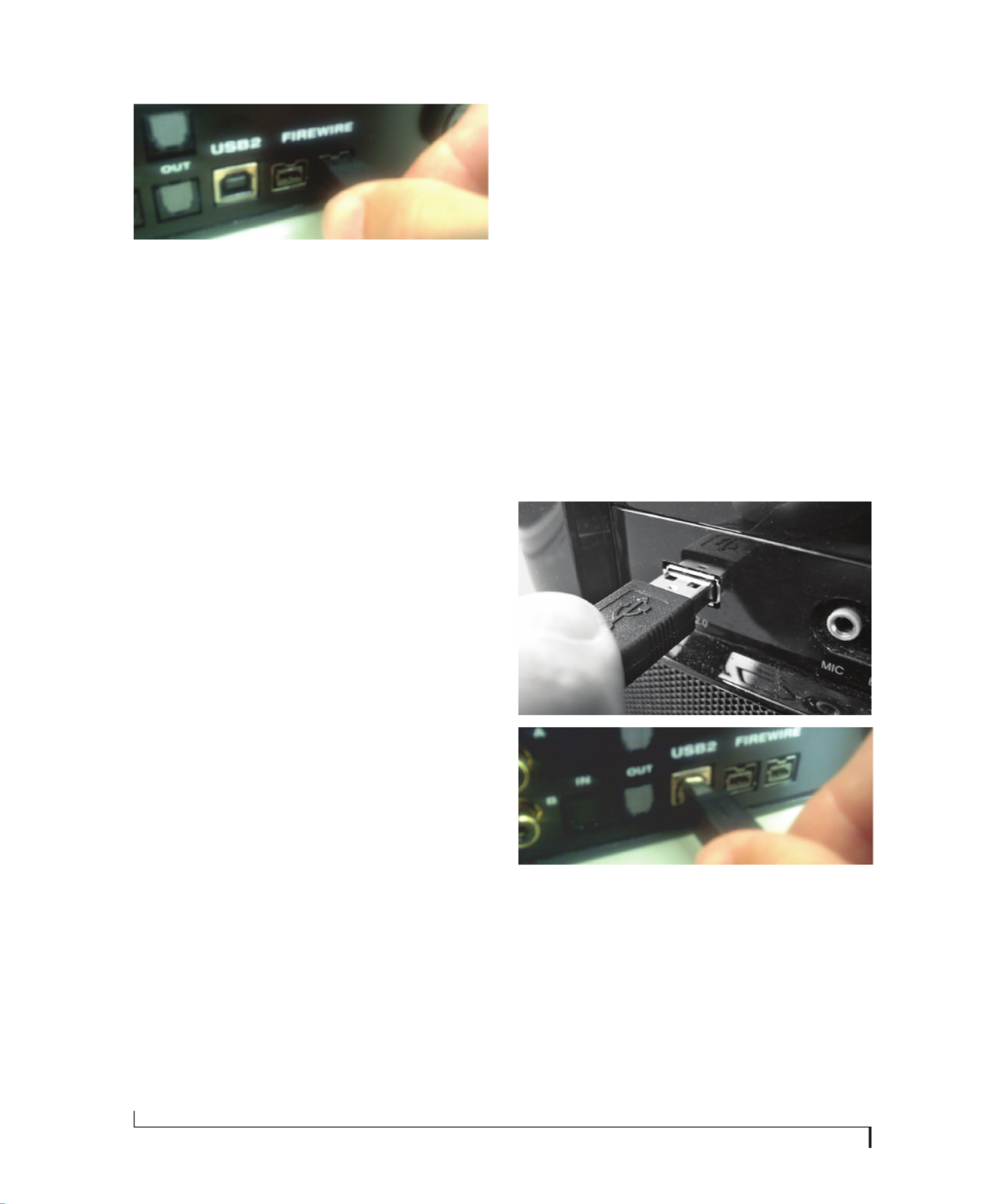
I N S T A L L I N G T H E 8 9 6 M K 3 H A R D W A R E
22
Figure 4-1: Connecting the 896mk3 to the computer via FireWire.
☛Make absolute sure to align the notched side
of the FireWire plug properly with the notched side
of the FireWire socket on the 896mk3. If you
attempt to force the plug into the socket the wrong
way, you can damage the 896mk3.
High Speed USB 2.0 versus USB 1.1
There are primarily two types of USB host
controllers widely available on current personal
computers. USB 1.1 controllers support simple
peripherals that don’t require a high speed
connection, such as a computer keyboard, a
mouse, or a printer. USB 2.0 controllers support
high speed devices such as the 896mk3. Since the
896mk3 requires a high speed connection, it must
be connected to a USB 2.0 host controller or hub.
For the most reliable connection, it is
recommended that you connect the 896mk3
directly to one of your computer’s USB 2.0-
compatible ports. However, since USB 2.0 hubs are
compatible with both types of devices, the 896mk3
can be connected to a USB 2.0 hub along with USB
1.1 devices if necessary. The 896mk3 will not
operate properly if it is connected to a USB 1.1 hub.
Follow these instructions to determine whether
your computer supports USB 1.1 or USB 2.0:
1 Open the Windows Control Panel, and choose
Hardware and Sound.
2 In the Devices and Printers section, click Device
Manager.
3 In Device Manager, open the Universal Serial
Bus Controllers section.
4 Look in the list of USB devices. An Enhanced
USB Host Controller Interface (EHCI) represents a
USB 2.0 controller. An Open USB Host Controller
Interface (OHCI) or Universal USB Host
Controller Interface (UHCI) represents a USB 1.1
controller.
If you are connecting via high-speed USB 2.0
1 Before you begin, make sure your computer and
the 896mk3 are switched off.
2 Plug the at “type A” plug of the 896mk3 USB
cable (included) into a USB2-equipped socket on
the computer as shown below in Figure 4-2.
3 Plug the squared “type B” plug of the USB cable
into the 896mk3 I/O as shown below in Figure 4-2.
Figure 4-2: Connecting the 896mk3 to the computer via USB.

I N S T A L L I N G T H E 8 9 6 M K 3 H A R D W A R E
23
CONNECT AUDIO INPUTS AND OUTPUTS
The 896mk3 audio interface has the following
audio input and output connectors:
■8 combo-style XLR/quarter-inch analog inputs
■8 XLR analog outputs
■2 XLR main outs
■AES/EBU input/output
■S/PDIF input/output
■ADAT optical input/output
Here are a few things you should keep in mind as
you are making these connections to other devices.
Analog inputs
Connect a microphone, guitar, instrument or line
level analog input to any XLR/quarter-inch combo
jack with either a standard mic cable or a balanced/
unbalanced cable with a quarter-inch plug.
Phantom power
If you are connecting a condenser microphone or
other device that requires phantom power, push
and hold the corresponding front-panel Trim
rotary encoder for a few seconds to toggle phantom
power. The red LED will turn on or off accordingly.
☛Always disable phantom power before
inserting a quarter-inch plug.
Trim
Both the XLR mic input and the high-impedance
quarter-inch guitar input are equipped with 53 dB
gain. Use the corresponding front panel trim knob
to adjust the input level as needed for each input.
The LCD provides visual feedback as you turn the
trim knob.
Figure 4-4: The LCD gives you feedback as you turn the TRIM knobs for
the analog inputs.
The 896mk3’s input trims are digitally controlled,
so they allow you to make ne-tuned adjustments
in 1 dB increments. You can also adjust trim in the
MOTU CueMix FX software. See “Input trim” on
page 80.
-20 dB pad
If the input signal is too hot with the trim turned all
the way down, engage the -20dB pad for the input
on the front panel. To toggle the -20 dB pad for an
input, quickly push its TRIM rotary encoder. The
green LED will turn on or off accordingly.
☛For line level quarter-inch inputs, turn on the
pad.
Figure 4-3: the 896mk3 front panel.
I N S T A L L I N G T H E 8 9 6 M K 3 H A R D W A R E
24
Combo jack summary
Use these general guidelines for the 48V phantom
power, pad and trim settings for the combo inputs:
Analog outputs
For the XLR outputs, use high-quality shielded
cables.
Main outs
The XLR main outputs serve as independent
outputs. From the factory, the main out volume is
controlled by the MASTER VOL knob on the front
panel, although this knob can be programmed to
control any combination of outputs. For details, see
“The Monitor Group” on page 95. In a standard
studio conguration, the main outs are intended
for a pair of studio monitors, but they can also be
used as additional outputs for any purpose.
Optical
The 896mk3 rear panel provides two sets of ADAT
optical (“lightpipe”) connectors: Bank A and B
(Figure 4-5). Each bank provides an input and
output connector. All four connectors can operate
independently and offer two different optical
formats: ADAT optical or TOSLINK (optical
S/PDIF). For example, you could connect
8-channel ADAT optical input from your digital
mixer and stereo TOSLINK output to an effects
processor.
The 896mk3 supplies +12dB of digital trim (boost)
for each optical input, which can be adjusted from
CueMix FX (“Input trim” on page 78) or the front
panel (“The IN (inputs) menu” on page 52).
Below is a summary of optical formats:
Optical operation at 44.1 or 48 kHz
When congured for ADAT “lightpipe”, an optical
connector provides 8 channels at 44.1 and 48 kHz.
ADAT optical operation at 88.2 or 96 kHz
When congured for ADAT “lightpipe”, an optical
connector provides four channels at 88.2 or 96 kHz
(2x sample rates). When using the ADAT lightpipe
format at a 2x rate, be sure to choose either Type I
or Type II operation, as explained in “ADAT SMUX
Type” on page 51.
Input 48V Pad Trim
Condenser mic On As needed As needed
Dynamic mic Off As needed As needed
Guitar Off Off As needed
-10 dB Line level via TRS Off On As needed
+4 dB Line Level via TRS Off On As needed
Format 44.1 or 48 kHz 88.2 or 96 kHz
ADAT optical 8 channels 4 channels
TOSLINK stereo stereo
Figure 4-5: the 896mk3 rear panel.

I N S T A L L I N G T H E 8 9 6 M K 3 H A R D W A R E
25
Using optical I/O to operate the 896mk3 as an
8-channel expander
When the 896mk3 is not connected directly to a
computer via FireWire or USB, the optical outputs
can be programmed (via the CueMix FX mixer) to
mirror the incoming signal on any combination of
the 896mk3’s inputs. By connecting the 896mk3
optical outputs to another device, such as another
ADAT-optical equipped interface or a digital
mixer, you add additional inputs to your system.
To learn how to program the 896mk3 when it is
operating as a stand-alone expander in this
fashion, see chapter 6, “Front Panel Operation”
(page 43).
Choosing a clock source for optical connections
Be sure to review the digital audio clocking issues,
as explained in “Syncing optical devices” on
page 30.
S/PDIF
If you make a S/PDIF digital audio connection to
another device, be sure to review the digital audio
clocking issues, as explained in “Syncing S/PDIF
devices” on page 29.
The 896mk3 supplies +12dB of digital trim (boost)
for the S/PDIF input pair, which can be adjusted
from CueMix FX (“Input trim” on page 78) or the
front panel (“The IN (inputs) menu” on page 52).
AES/EBU
Connect standard AES/EBU input and output. 2x
sample rates (88.2 & 96 kHz) are supported; 4x
samples rates (176.4 or 192kHz) are not supported.
Be sure to review the digital audio clocking issues,
as explained in “Syncing AES/EBU devices” on
page 30.
The 896mk3 supplies +12dB of digital trim (boost)
for the AES/EBU input pair, which can be adjusted
from CueMix FX (“Input trim” on page 78) or the
front panel (“The IN (inputs) menu” on page 52).
CONNECT A FOOT SWITCH
If you would like to use a foot switch with your
896mk3, connect it to the FOOT SWITCH jack.
See “Enable Pedal” on page 43 for information
about how to program the foot switch to trigger
any computer keystroke you wish.

I N S T A L L I N G T H E 8 9 6 M K 3 H A R D W A R E
26
A TYPICAL 896MK3 SETUP
Here is a typical 896mk3 studio setup. This rig can
be operated without a conventional mixer. All
mixing and processing can be done either in the
896mk3, in the computer with audio software, or
both. During recording, you can use the 896mk3’s
CueMix™ FX mixer to apply reverb, EQ and
compression to what you are recording and
monitor it via the main outs, headphone outs, or
any other output pair. You can control everything
from the included CueMix Console software.
Figure 4-6: A typical 896mk3 studio setup.
Pedal jack (on front panel)
mic
AES/EBU
DAT deck
quarter-inch analog outs
synthesizer
monitors
guitar
quarter-inch analog outs
synths, samplers, effects units, etc.
sends to
FX unit (in
rack
below)
headphones
Headphone jack (on front panel)
other outputs
(stage
monitors,
etc.)
foot switch
PC
MOTU 8pre and/or
other optical devices
Optical output
FireWire or USB

I N S T A L L I N G T H E 8 9 6 M K 3 H A R D W A R E
27
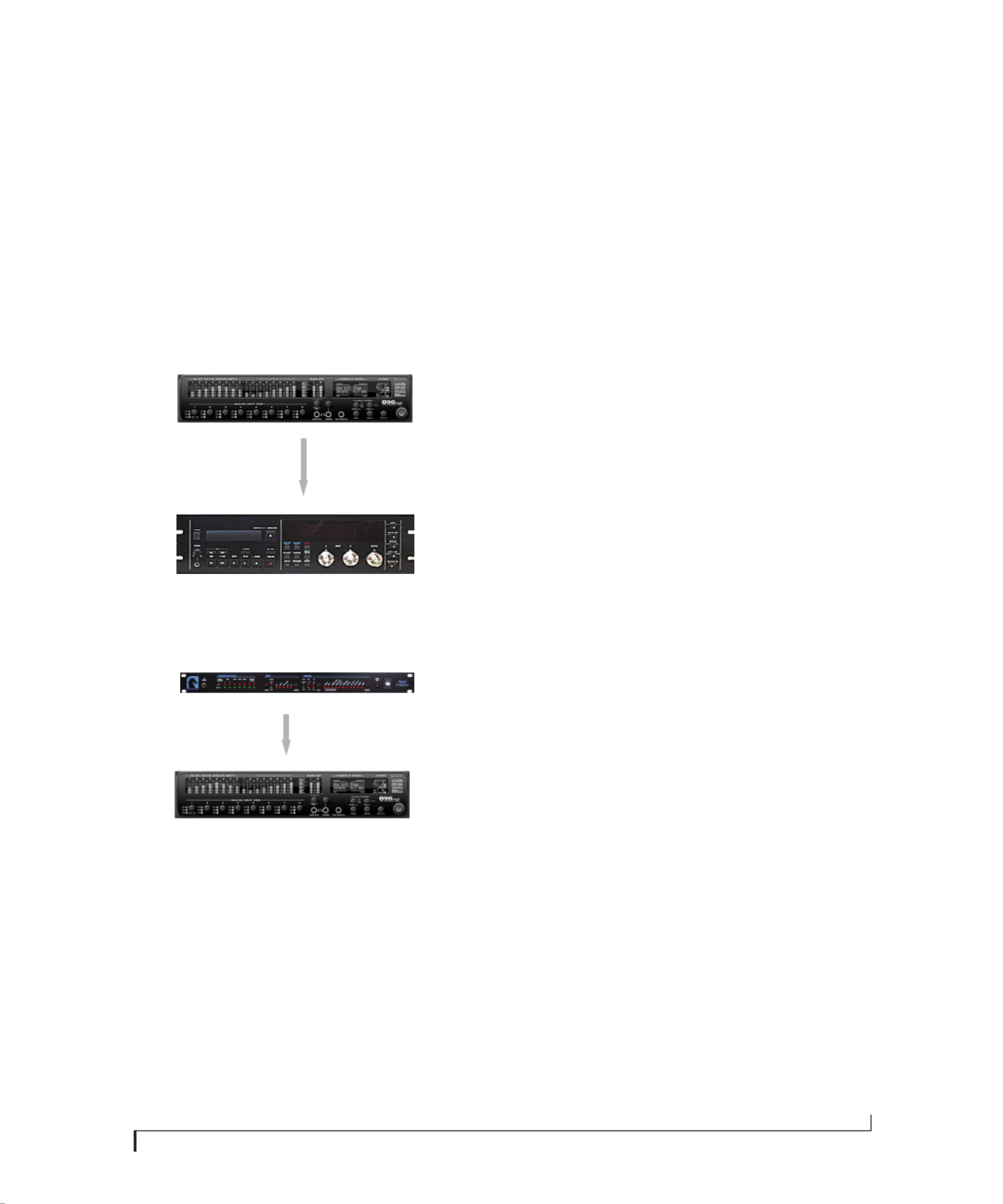
OPERATING THE 896mk3 AS A CONVERTER
As explained earlier in “Using optical I/O to
operate the 896mk3 as an 8-channel expander” on
page 25, the 896mk3 can serve as a multi-channel
analog-to-digital converter when disconnected
from the computer and instead connected to
another device equipped with an ADAT optical
input. For example, you could connect the 896mk3
optical output to the optical input on another
MOTU audio interface, such as a Traveler, 828mk3
or even another 896mk3. The 896mk3 then serves
as a multi-channel expander that adds additional
mic/analog and digital inputs to the interface. The
benet of connecting the 896mk3 in this manner
(instead of as another FireWire interface) is that
you can seamlessly integrate the 896mk3’s inputs
into the on-board no-latency CueMix monitor
mixing in the interface, since the 896mk3’s inputs
are fed into CueMix via the interface’s optical
inputs.
If the device to which you are connecting the
896mk3 supports 2x optical sample rates (88.2 or
96 kHz), you can also use both banks of connectors
as discussed in “ADAT optical operation at 88.2 or
96 kHz” on page 24.
Expander
896mk3
ADAT optical Out
Figure 4-7: Using the 896mk3 as an optical expander. In this example, it is connected to another 896mk3.
FireWire or USB
Base
896mk3
PC
ADAT optical In

I N S T A L L I N G T H E 8 9 6 M K 3 H A R D W A R E
28
MAKING SYNC CONNECTIONS
If you connect devices digitally to the 896mk3, or if
you need to synchronize the 896mk3 with an
outside time reference such as SMPTE time code,
you must pay careful attention to the synchroni-
zation connections and clock source issues
discussed in the next few sections.
Do you need to synchronize the 896mk3?
If you will be using only the 896mk3’s analog
inputs and outputs (and none of its digital I/O),
and you have no plans to synchronize your 896mk3
system to SMPTE time code or other external clock
source, you don’t need to make any sync
connections. You can skip this section and proceed
to chapter 5, “MOTU Audio Console” (page 39),
where you’ll open MOTU Audio Console and set
the Master Clock Source setting to Internal as
shown below. For details, see chapter 5, “MOTU
Audio Console” (page 39).
Figure 4-8: You can run the 896mk3 under its own internal clock
when it has no digital audio connections and you are not synchroniz-
ing the 896mk3 system to an external time reference such as SMPTE
time code.
Situations that require synchronization
There are three general cases in which you will
need to resolve the 896mk3 with other devices:
■Synchronizing the 896mk3 with other digital
audio devices so that their digital audio clocks are
phase-locked (as shown in Figure 4-9)
■Resolving the 896mk3 system to SMPTE time
code from a video deck, analog multi-track, etc.
■Both of the above
Synchronization is critical for clean digital I/O
Synchronization is critical in any audio system, but
it is especially important when you are transferring
audio between digital audio devices. Your success
in using the 896mk3’s digital I/O features depends
almost entirely on proper synchronization. The
following sections guide you through several
recommended scenarios.
Be sure to choose a digital audio clock master
When you transfer digital audio between two
devices, their audio clocks must be in phase with
one another — or phase-locked. Otherwise, you’ll
hear clicks, pops, and distortion in the audio — or
perhaps no audio at all.
Figure 4-9: When transferring audio, two devices must have phase-
locked audio clocks to prevent clicks, pops or other artifacts.
There are two ways to achieve phase lock: slave one
device to the other, or slave both devices to a third
master clock. If you have three or more digital
audio devices, you need to slave them all to a single
master audio clock.
Figure 4-10: To keep the 896mk3 phased-locked with other digital
audio devices connected to it, choose a clock master.
Also remember that audio phase lock can be
achieved independently of time code (location).
For example, one device can be the time code
master while another is the audio clock master. But
only one device can be the audio clock master. If
you set things up with this rule in mind, you’ll have
trouble-free audio transfers with the 896mk3.
Not phase-locked Phase-locked
Device A
Device B
Master
Slave
Master
Slave Slave

I N S T A L L I N G T H E 8 9 6 M K 3 H A R D W A R E
29
SYNCING S/PDIF DEVICES
S/PDIF devices will sync to the 896mk3 in one of
two ways:
■Via the S/PDIF connection itself
■Via word clock
S/PDIF devices with no word clock
If your S/PDIF device has no word clock sync
connectors, just connect it to the 896mk3 via the
S/PDIF connectors. When the device records
S/PDIF audio (from the 896mk3), it will simply
synchronize to the clock provided by the audio
input.
On the other hand, when you transfer audio from
the S/PDIF device into the 896mk3, you’ll have to
slave the 896mk3 to its S/PDIF input. If you have
other digital audio devices connected to the
896mk3, and they are not slaved directly to the
896mk3 itself, you may hear clicks and pops
resulting from their unsynchronized audio clock. If
so, just turn them off during the transfer.
S/PDIF devices with word clock
If your S/PDIF device has a Word Clock input, slave
the S/PDIF device to the 896mk3 via their word
clock connection. You can then freely transfer
audio between the 896mk3 and the S/PDIF device.
S/PDIF
S/PDIF
DAT deck
or other S/PDIF device
896mk3
896mk3
Master Clock Source setting =
Internal (when transferring from the
896mk3 to the S/PDIF device)
Figure 4-11: Two setups for synchronizing a S/PDIF device with the 896mk3. In the top diagram, sync is achieved via the S/PDIF connection itself.
In this case, you have to choose S/PDIF as the 896mk3’s clock source when recording from the S/PDIF device. If you don’t want to have to worry
about switching the Clock Source setting depending on the direction of the S/PDIF transfer, you can slave the S/PDIF device to word clock from
the 896mk3 or vice versa (not shown). The Word Clock connection maintains sync, regardless of the direction of the transfer.
896mk3
Clock Source setting =
S/PDIF (when transferring from
the S/PDIF device to the 896mk3)
SPDIF
SPDIF
DAT deck
or other SPDIF device
896mk3
Word Clock Out
Word Clock In
896mk3
Clock Source setting = Internal
With this setup, in the MOTU Audio Console window, choose Internal, or any other
clock source setting except SPDIF. The DAT deck (or other SPDIF device) slaves to the
896mk3 via word clock for SPDIF transfers in both directions.

I N S T A L L I N G T H E 8 9 6 M K 3 H A R D W A R E
30
SYNCING OPTICAL DEVICES
When connecting an optical device, make sure that
its digital audio clock is phase-locked (in sync
with) the 896mk3, as explained in “Making sync
connections” on page 28. There are two ways to do
this:
1. Resolve the optical device to the 896mk3
2. Resolve the 896mk3 to the optical device
For 1), choose Internal (or any other clock source
except ADAT optical) as the clock source for the
896mk3 in MOTU Audio Console.
For 2), choose either ADAT Optical A or ADAT
Optical B as the 896mk3’s clock source
(Figure 4-12). Be sure to choose the optical port
that the device is connected to.
Figure 4-12: Resolving the 896mk3 to an optical device.
For details about using the clock source setting and
the MOTU Audio Console software in general, see
chapter 5, “MOTU Audio Console” (page 39).
Using word clock to resolve optical devices
If the optical device you are connecting to the
896mk3 has word clock connectors on it, you can
use them to resolve the device to the 896mk3,
similar to the diagram shown in Figure 4-11 on
page 29 for S/PDIF devices with word clock. Also
see “Syncing word clock devices” on page 33.
SYNCING AES/EBU DEVICES
If you would like to transfer stereo audio digitally
between the 896mk3 and another device that has
AES/EBU, connect it to the 896mk3’s AES/EBU
jacks with balanced, AES/EBU grade audio cables.
AES/EBU clock and sample rate conversion
The 896mk3 AES/EBU section is equipped with a
real-time sample rate converter that can be used for
either input or output. This feature provides a great
deal of exibility in making digital transfers. For
example, you can:
■Transfer digital audio into the 896mk3 at a
sample rate that is completely different than the
896mk3 system clock rate.
■Transfer digital audio into the 896mk3 without
the need for any external synchronization
arrangements.
■Transfer digital audio out of the 896mk3 at
double or half the 896mk3 system clock rate.
Rate conversion does not add any appreciable noise
to the audio signal (under -120 dB).
Digital audio phase lock
Without sample rate conversion, when you transfer
digital audio between two devices, their audio
clocks must be in phase with one another — or
phase-locked — as discussed earlier in “Be sure to
choose a digital audio clock master” on page 28
and Figure 4-10 on page 28. Otherwise, you’ll hear
clicks, pops, and distortion in the audio, or
perhaps no audio at all. Phase lock ensures a clean
digital audio transfer.
Another benet of direct master/slave clocking
(without sample rate conversion) is that each
slaved device remains continuously resolved to the
master, which means that there will be no gradual
drift over time. This form of synchronization is
best for audio that needs to remain resolved to lm,
video, etc.

I N S T A L L I N G T H E 8 9 6 M K 3 H A R D W A R E
31
Sample rate conversion
With sample rate conversion (SRC), an extra level
of master/slave clocking is added to the equation,
as demonstrated below in Figure 4-13, which
shows the clocking going on when you transfer
digital audio from the 896mk3 (AES/EBU OUT) to
a DAT deck (AES/EBU IN) using SRC. Notice that
with SRC, the DAT deck is not slaved to the
896mk3’s system clock. Instead, their clocks are
running completely independently of one another.
But also notice that the DAT deck must still slave to
the sample-rate-converted output from the
896mk3 for a clean digital audio transfer (unless it
has its own sample rate converter on its AES/EBU
input).
Figure 4-13: Clock relationships when sending audio from the
896mk3 to a DAT deck using sample rate conversion. The DAT deck
needs to be slaving to its AES/EBU input. *Note: the 896mk3 AES/EBU
output can actually be clocked from a number of different sources. In
this example, it is resolved to the 896mk3 system clock. For details
about other possible clock sources, see “Clocking scenarios for AES/
EBU output” on page 32.
System clock, AES clock & rate convert settings
When you are setting up AES/EBU input and
output with the 896mk3, pay careful attention to
the following settings in MOTU Audio Console
(see the quick reference overview on page 9):
■Clock source
■Sample rate conversion
These options are mentioned briey in the
following sections. For further details, see “Master
Clock Source” on page 41 and “Sample Rate
Convert” on page 44.
Clocking scenarios for AES/EBU input
There are three possible clocking scenarios for the
896mk3 AES/EBU input:
1. Simple transfer (slave the 896mk3 system clock
to the AES/EBU input signal — no sample rate
conversion).
2. Sample rate convert the AES/EBU input.
3. Use word clock to resolve the 896mk3 system
clock and the other AES/EBU device with each
other.
These three AES/EBU input scenarios are
summarized below.
896mk3 master clock
Input
clock
Output
clock
896mk3
Sample Rate
converter
(slaves to 896mk3 SRC output clock)
(master)
(slaves to 896mk3 master clock)
DAT deck
(master*)
Scenario 1 Scenario 2 Scenario 3
Description Simple
transfer
Rate
convert
Use word
clock
896mk3 clock
source setting AES/EBU Any setting
except
AES/EBU
Word Clock
Sample rate
conversion
setting
None AES In None
Required
896mk3 cable
connections
AES/EBU In AES/EBU In AES/EBU In
and Word
Clock In
Are the devices
continuously
resolved?
Yes No Yes
Is the signal
being sample
rate converted?
No Yes No
Example
application Simple digital
transfer into
the 896mk3
from DAT
deck or digi-
tal mixer.
Transfer from
digital mixer
running at a
different
sample rate.
Both the
896mk3 and
other AES/
EBU device
are slaved to
‘house” word
clock.

I N S T A L L I N G T H E 8 9 6 M K 3 H A R D W A R E
32
Some example scenarios are demonstrated below.
Simple AES/EBU input transfer (no rate convert)
Figure 4-14: Slaving the 896mk3 to an AES/EBU device. For the
896mk3’s clock source, choose ‘AES/EBU’.
AES/EBU input with rate conversion
Figure 4-15: Rate-converting AES/EBU input.
AES/EBU input with word clock
Figure 4-16: In this scenario, the 896mk3 and other AES/EBU device
are both resolved to one another via a third master word clock
source.
Clocking scenarios for AES/EBU output
The 896mk3 AES/EBU output can also employ
sample rate conversion. The output options, shown
below in Figure 4-17, are briey summarized in the
following sections. For further details, see “Sample
Rate Convert” on page 44.
Figure 4-17: The Sample Rate Conversion option in MOTU Audio
Console gives you access the AES/EBU output clock options.
None
To make the AES/EBU output sample rate match
the System sample rate, choose None (Figure 4-17).
No sample rate conversion occurs when this setting
is chosen.
AES Out slave to AES In
To make the AES/EBU output sample rate match
the sample rate currently being received by the
896mk3’s AES/EBU input, choose AES Out Slave to
AES In (Figure 4-17). This setting requires a
connection to the 896mk3’s AES/EBU input from a
device that is transmitting an AES/EBU clock
signal.
☛Be careful when both the 896mk3’s AES/EBU
input and output are connected to the same
external device: this option is likely to create a
clock loop.
AES/EBU Out options
Choose the desired AES/EBU Out sample rate
options (Figure 4-17) when the desired AES/EBU
output rate needs to be completely different than
the system clock rate or the AES In clock rate.
Master
Slave
AES/EBU OUT
AES/EBU IN
Other device 896mk3 clock source
setting: AES/EBU
896mk3 896mk3 Sample Rate
Conversion setting: None
Master
Slave
AES/EBU OUT
AES/EBU IN
Other device
896mk3 clock source
setting: Internal
896mk3 896mk3 Sample Rate
Conversion setting:
AES In
(Slave)
(Slave)
AES/EBU OUT/IN
AES/EBU IN/OUT
Other device
896mk3 clock
source: word clock
896mk3
Word clock IN
Word clock IN
896mk3 Sample
Rate Conversion
setting: None
‘House’ word clock master
I N S T A L L I N G T H E 8 9 6 M K 3 H A R D W A R E
33
SYNCING WORD CLOCK DEVICES
The 896mk3 word clock connectors allow you to
synchronize it with a wide variety of other word
clock-equipped devices.
For standard word clock sync, you need to choose
an audio clock master (as explained in “Be sure to
choose a digital audio clock master” on page 28).
In the simplest case, you have two devices and one
is the word clock master and the other is the slave
as shown below in Figure 4-18 and Figure 4-19.
Figure 4-18: Slaving another digital audio device to the 896mk3 via
word clock. For the 896mk3 clock source, choose any source besides
word clock, as it is not advisable to chain word clock.
Figure 4-19: Slaving the 896mk3 to word clock. For the 896mk3 clock
source, choose ‘Word Clock In’.
Don’t chain word clock
If you have three or more digital audio devices that
you need to synchronize, avoid chaining their word
clock connections (OUT to IN, OUT to IN, etc.), as
this causes problems. Instead, use a dedicated
synchronizer like the Digital Timepiece or a word
clock distribution device of some kind.
Slaving to a 2x and 1/2x word clock
All MOTU FireWire audio interfaces that support
96 kHz operation have the ability to slave to a word
clock signal running at either one half or one
quarter of their current clock rate. For example, the
896mk3 could be running at 96 kHz while slaving
to a 48 kHz word clock signal. Similarly, the
896mk3 could run at 88.2 kHz and slave to
44.1 kHz word clock.
Remember, the word clock signal must be one of
the following:
■the same as the 896mk3 clock
■half of the 896mk3 clock
Forcing a 1x word out rate
The 896mk3 can generate a word clock output
signal that either matches the current system clock
rate (any rate between 44.1 and 192kHz) or the
corresponding 1x rate. For example, if the 896mk3
is operating at 192kHz, you can choose to generate
a word out rate of 48kHz. For details on how to
make this word clock output setting, see “Word
Out” on page 45.
Master
Slave
Word clock OUT
Word clock IN
Other device
896mk3
Audio
Clock
Master
Slave
MOTU Digital Timepiece universal synchronizer
Word clock OUT
Word clock IN
896mk3

I N S T A L L I N G T H E 8 9 6 M K 3 H A R D W A R E
34
SYNCING TO SMPTE TIME CODE
The 896mk3 system can resolve directly to SMPTE
time code. It can also generate time code and word
clock, under its own clock or while slaving to time
code. Therefore, the 896mk3 can act both as an
audio interface and as a digital audio synchronizer
to which you can slave other digital audio devices.
You can use the 896mk3 to slave your audio
software to SMPTE as well, via sample-accurate
sync (if your host software supports it).
Other digital audio device
slaved to the 896mk3
Figure 4-20: Connections for synchronizing
the 896mk3 directly to SMPTE time code.
Choose SMPTE as the clock source in MOTU
Audio Console. This setting can also be made in
the MOTU SMPTE Console (shown below).
SMPTE time code
source
audio cable bearing LTC
(Longitudinal Time Code)
FireWire or USB cable
Launch the MOTU SMPTE Console and specify the SMPTE Source,
which is the input receiving the SMPTE time code. Also, conrm that
the Clock Source/Address is SMPTE/SMPTE. For details about the other
settings, see chapter 10, “MOTU SMPTE Console” (page 119).
BNC
cable
audio
cable
Analog
out
Word
Out
Windows computer running Cubase or
other sample-accurate ASIO software
In Cubase, go to the Synchronization window and
choose ASIO Audio Device as the Timecode Base.
896mk3 interface
Any analog Input
(Input 8 in this example)
Use this setup if you have:
✓A SMPTE time code source, such as a multitrack tape deck.
✓An 896mk3 by itself, OR with another slaved device (such as a
digital mixer).
✓Host software that supports sample-accurate sync (such as
Cubase or Nuendo).
This setup provides:
✓Continuous sync to SMPTE time code.
✓Sub-frame timing accuracy.
✓Transport control from the SMPTE time code source.

I N S T A L L I N G T H E 8 9 6 M K 3 H A R D W A R E
35
CONNECTING MULTIPLE MOTU FIREWIRE
INTERFACES
You can daisy-chain up to three MOTU FireWire
interfaces on a single FireWire bus, with the
restrictions described in the following sections.
Most computers have only one built-in FireWire
bus (even if it supplies multiple FireWire sockets).
Connect them as follows:
Figure 4-21: Connecting multiple 896mk3’s (or other MOTU FireWire
audio interfaces) to a computer.
Multiple interfaces cannot be bus-powered
Do not run the Traveler, UltraLite or other bus-
powered interfaces under bus power when
connecting them with other devices on the same
FireWire bus.
Multiple interfaces in MOTU Audio Console
MOTU Audio Console displays the settings for one
interface at a time. To view the settings for an
interface, click its tab as shown below in
Figure 4-22.
Figure 4-22: To view the settings for an interface, click its tab.
Synchronizing multiple interfaces
When multiple MOTU interfaces are connected,
choose a Master Clock Source from the menu in the
General tab (Figure 4-23). You can choose any
available sync source from any connected interface
(as shown in Figure 4-23), giving you a great deal
of exibility in choosing a clock source.
A separate Clock menu is provided for any
interfaces not chosen as the master clock source, as
demonstrated with the 896mk3 Hybrid in
Figure 4-23. You can either resolve the interface to
the Master Clock Source or to one of its own digital
inputs or other sync sources. The latter scenario is
useful for externally resolving the interface with the
the interface chosen as the Master Clock Source.
FireWire
FireWire
FireWire
FireWire
FireWire
FireWire
PC
Word Clock Out
Word Clock In
Word Clock Out
Word Clock In
For two
interfaces,
slave one to
the other.
You can probably
get away with
daisy-chaining
three interfaces,
although a word
clock distribu-
tion device is
recommended.

Part 2
Using the
896mk3 Hybrid


M O T U A U D I O C O N S O L E
40
‘GENERAL’ TAB SETTINGS
Sample Rate
Choose the desired Sample Rate for recording and
playback. The 896mk3 can operate at 44.1 (the
standard rate for compact disc audio), 48, 88.2, 96,
176.4 or 192KHz. If you are operating at a sample
rate between 44.1 and 96kHz, make absolutely sure
that all of the devices connected digitally to the
896mk3 match the 896mk3’s sample rate. Also
make sure that your digital audio synchronizer
matches it as well. At the 4x sample rates (176.4 or
192kHz), all digital I/O on the 896mk3 is disabled.
☛Mismatched sample rates cause distortion and
crackling. If you hear this sort of thing, check the
sample rate settings in your hardware and here in
MOTU Audio Console.
Operation at 4x sample rates (176.4 or 192kHz)
At the 4x sample rates (176.4 or 192kHz),
operation of the 896mk3 is restricted, due to the
higher audio bandwidth demands, as follows:
■All digital I/O is disabled (there is no optical,
S/PDIF or AES/EBU input/output).
■The 896mk3 provides 8 channels of analog input
and 8 channels of analog output, simultaneously.
■The stereo return bus, as described in “Return
Assign” on page 44, can only be assigned to one of
the four available analog output pairs or main outs.
■The PHONES jack can only be assigned to one
of the four available analog output pairs or the
main outs.
■The MAIN OUT jack can only be assigned to
one of four analog output pairs or the main outs.
Figure 5-1: MOTU Audio Console gives you access to all of the settings in the 896mk3 hardware.

M O T U A U D I O C O N S O L E
41
Master Clock Source
The Master Clock Source determines the digital
audio clock that the 896mk3 will use as its time
base. For a complete explanation of synchroni-
zation issues, see “Making sync connections” on
page 28. The following sections briey discuss each
clock source setting.
Internal
Use the Internal setting when you want the 896mk3
to operate under its own digital audio clock. For
example, you may be in a situation where all you
are doing is playing tracks off hard disk in your
digital audio software on the computer. In a
situation like this, you most often don’t need to
reference an external clock of any kind.
Another example is transferring a mix to DAT. You
can operate the 896mk3 system on its internal
clock, and then slave the DAT deck to the 896mk3
via the AES/EBU connection (usually DAT decks
slave to their AES/EBU input when you choose the
AES/EBU input as their record source) or via the
896mk3’s word clock output (if your DAT deck has
a word clock input).
If you would like help determining if this is the
proper clock setting for your situation, see
“Making sync connections” on page 28.
Word Clock In
The Word Clock In setting refers to the Word Clock
In BNC connector on the 896mk3 rear panel.
Choosing this setting allows the 896mk3 to slave to
an external word clock source, such as the word
clock output from a digital mixer.
S/PDIF
The S/PDIF clock source setting refers to the
S/PDIF RCA input jack on the 896mk3. This
setting allows the 896mk3 to slave to another
S/PDIF device.
Use this setting whenever you are recording input
from a DAT deck or other S/PDIF device into the
896mk3. It is not necessary in the opposite
direction (when you are transferring from the
896mk3 to the DAT machine).
For further details about this setting, see “Syncing
S/PDIF devices” on page 29.
AES/EBU
The AES/EBU clock source setting refers to the
AES/EBU input connector on the 896mk3. This
setting allows the MOTU 896mk3 to slave to
another AES/EBU device.
Use this setting whenever you are recording input
from a DAT deck or other AES/EBU device into the
896mk3. It is not necessary in the opposite
direction (when you are transferring from the
896mk3 to the DAT machine).
For further details about this setting, see “Syncing
AES/EBU devices” on page 30.
ADAT optical A / B
The ADAT optical clock source settings (ADAT
Optical A and ADAT Optical B) refer to the clock
provided by the 896mk3’s two optical inputs, when
either one is connected to another optical device.
These two settings only appear in the Master Clock
Source menu when their corresponding optical
bank input is enabled and set to the ADAT Optical
format, as explained in “Optical input/output” on
page 44.
This setting can be used to resolve the 896mk3
directly to the optical input connection. Most of
the time, you can set up a better operating scenario
that uses one of the other synchronization options.
However, there may be occasions when you have an
optical device that has no way of synchronizing
digitally to the 896mk3 or an external

M O T U A U D I O C O N S O L E
42
synchronizer. In this case, the ADAT Optical clock
source setting lets you slave the 896mk3 to the
device itself via its digital input to the 896mk3.
This setting is also useful if you just need to make a
simple, click-free digital transfer between the
896mk3 and another device — where a time code
reference and shared transport control are not
needed — without having to set up an elaborate
synchronization scenario.
For further details about this setting, see “Syncing
optical devices” on page 30.
TOSLINK A / B
The TOSLINK clock source settings (TOSLINK A
and TOSLINK B) refer to the clock provided by the
896mk3’s two optical inputs, when either one is
connected to another optical device. These two
settings only appear in the Master Clock Source
menu when their corresponding optical bank input
is enabled and set to the TOSLINK format, as
explained in “Optical input/output” on page 44.
The TOSLINK clock source setting refers to the
clock provided by an optical S/PDIF device
connected to the 896mk3’s optical input. This
setting can be used to slave the 896mk3 directly to
the optical input connection. Most of the time, you
can set up a better operating scenario that uses one
of the other synchronization options. However,
there may be occasions when you have a
TOSLINK-compatible device that has no way of
synchronizing digitally to the 896mk3 or an
external synchronizer such as the Digital
Timepiece. In this case, the TOSLINK clock source
setting lets you slave the 896mk3 to the other
device via the 896mk3’s optical input.
This setting is also useful if you just need to make a
simple, click-free digital transfer between the
896mk3 and another device — where a time code
reference and shared transport control are not
needed — without having to set up an elaborate
synchronization scenario.
For further details, see “Syncing optical devices”
on page 30.
SMPTE
Choose this setting to resolve the 896mk3 directly
to SMPTE time code (LTC) being received via the
896mk3’s quarter-inch SMPTE input jack. For
details, see “Syncing to SMPTE time code” on
page 34 and chapter 10, “MOTU SMPTE Console”
(page 119).
Samples Per Buffer
The Samples Per Buffer setting lets you reduce the
delay you hear when patching live audio through
your audio software. For example, you might have
a live guitar input that you would like to run
through an amp simulation plug-in that you are
running in your host audio software. When doing
so, you may hear or feel some “sponginess” (delay)
between the source and the processed signal. If so,
don’t worry. This effect only affects what you hear:
it is not present in what is actually recorded.
You can use Samples Per Buffer setting to reduce
this monitoring delay—and even make it
completely inaudible.
☛If you don’t need to process an incoming live
signal with software plug-ins, you can monitor the
signal with no delay at all using CueMix FX, which
routes the signal directly to your speakers via
hardware. For details, see chapter 9, “CueMix FX”
(page 71).
Adjusting the Samples Per Buffer setting impacts
the following things:
■The strain on your computer’s CPU
■The delay you hear when routing a live signal
through your host audio software plug-ins

M O T U A U D I O C O N S O L E
43
■How responsive the transport controls are in
your software
This setting presents you with a trade-off between
the processing power of your computer and the
delay of live audio as it is being processed by
plug-ins. If you reduce the Samples Per Buffer, you
reduce patch thru latency, but signicantly increase
the overall processing load on your computer,
leaving less CPU bandwidth for things like real-
time effects processing. On the other hand, if you
increase the Samples Per Buffer, you reduce the load
on your computer, freeing up bandwidth for
effects, mixing and other real-time operations. But
don’t set the Samples Per Buffer too low, or it may
cause distortion in your audio.
If you don’t process live inputs with software
plug-ins, leave this setting at its default value of
1024 samples. If you do, try settings of 256 samples
or less, if your computer seems to be able to handle
them. If your host audio software has a processor
meter, check it. If it starts getting maxed out, or if
the computer seems sluggish, raise the Samples Per
Buffer until performance returns to normal.
If you are at a point in your recording project where
you are not currently working with live, patched-
thru material (e.g. you’re not recording vocals), or
if you have a way of externally monitoring input,
choose a higher Samples Per Buffer setting.
Depending on your computer’s CPU speed, you
might nd that settings in the middle work best.
The Samples Per Buffer setting also impacts how
quickly your audio software will respond when you
begin playback, although not by amounts that are
very noticeable. Lowering the Samples Per Buffer
will make your software respond faster; raising the
Samples Per Buffer will make it a little bit slower, but
barely enough to notice.
Monitoring live inputs without plug-in effects
As mentioned earlier, CueMix FX allows you to
monitor dry, unprocessed live inputs with no delay
at all. For complete details, see chapter 8,
“Reducing Monitoring Latency” (page 65).
Use stereo pairs for Windows audio
Some legacy Windows audio applications require
audio channels to be grouped in stereo pairs. If you
are using old Windows audio software, and you are
having issues accessing Audio Express channels
from within the software, try enabling the Use
Stereo Pairs for Windows Audio option.
Use WaveRT for Windows audio
If your host software supports WaveRT, enable this
option. Consult your host application
documentation for details.
Enable Pedal
Check the Enable Pedal option if a foot switch is
connected to the 896mk3 and you would like to
trigger recording punch in/out (or other software
functions) with it. Use the Set buttons to determine
what keystroke is triggered by the pedal-up and
pedal-down positions. You can assign the pedal to
any two keystrokes you wish. (You are not
restricted to punch in/out.)
896MK3 TAB SETTINGS
Phones Assign
The Phones Assign setting lets you choose what you
will hear from the headphone jack. Choose Main
Out 1-2 if you’d like to route the Main Out stereo
pair to the PHONES jack. Choose Phones 1-2 if you
would like the headphones to serve as their own
independent output, which you can access as an
independent output destination in your host audio
software and as an output destination for the four
on-board CueMix FX mix busses.

M O T U A U D I O C O N S O L E
44
Optical input/output
The Optical input and Optical output settings let
you choose between ADAT optical (‘lightpipe’) and
S/PDIF optical (‘TOSLINK’) as the format for the
896mk3’s two banks of optical input and output
(Bank A and Bank B). Choose the format that
matches the device connected. If you are not using
the optical connections, it is recommended that
you turn them off (by choosing Disabled from the
menu) to reduce bandwidth and processing
overhead. Note that you can operate each optical
port independently. For example, you could use the
ADAT optical format on the Bank A input (for a
digital mixer) and optical S/PDIF on the Bank A
output (for a DAT deck).
Main Out Assign
Choose Main Outs from the Main Out Assign menu
to treat the Main Outs as their own independent
output pair. Choose any other output pair to cause
the MAIN OUT jacks to mirror (duplicate) the
output pair you choose.
Return Assign
The Return Assign menu lets you choose any pair of
896mk3 audio outputs. The audio signal from this
output pair is then sent back to the computer via
the Stereo Return 1-2 bus. This stereo return bus
from the 896mk3 appears in your host software
alongside all other 896mk3 inputs, wherever your
host software lists them.
The 896mk3 stereo return bus can be used for a
variety of purposes. For example, you could use it
to send a nal mix being played through the
896mk3 back to the computer, where you could
record it for mastering or archiving purposes.
As another example, you could use the stereo
return bus to capture tracks played from your host
software, along with live inputs being routed
directly through the 896mk3 hardware via CueMix
FX (with or without CueMix effects processing on
the live inputs).
Programmable Meters
This option lets you choose which bank you wish
to monitor with the eight programmable meters on
the MOTU 896mk3 front panel. Your choices are:
Analog Out, Optical A In, Optical A Out, Optical B
In, Optical B Out, or Digital In/Out. This last
option displays AES/EBU input, S/PDIF input,
AES/EBU output and S/PDIF output, in order
from left to right. You can also adjust this setting by
turning the METERS knob on the 896mk3 front
panel.
Sample Rate Convert
The Sample Rate Convert option (Figure 4-17 on
page 32) lets you control AES/EBU sample rate
conversion. Sample rate conversion is available
when the 896mk3 is operating at the 1x sample
rates (44.1 and 48kHz) or the 2x sample rates (88.2
or 96kHz). AES/EBU is disabled entirely at the 4x
samples rates (176.4 and 192kHz). Each option is
explained below.
None
To make the AES/EBU output sample rate match
the System sample rate, choose None (Figure 4-17
on page 32). No sample rate conversion occurs
when this setting is chosen.
AES Out slave to AES In
To make the AES/EBU output sample rate match
the sample rate currently being received by the
896mk3’s AES/EBU input, choose AES Out Slave to
AES In (Figure 4-17 on page 32). This setting
requires a connection to the 896mk3’s AES/EBU
input from a device that is transmitting an AES/
EBU clock signal.
☛Be careful when both the 896mk3’s AES/EBU
input and output are connected to the same
external device: this option is likely to create a
clock loop.

M O T U A U D I O C O N S O L E
45
AES/EBU Out options
Choose the desired AES/EBU Out sample rate
options (Figure 4-17 on page 32) when the desired
AES/EBU output rate needs to be completely
different than the system clock rate or the AES In
clock rate. For further details about this option, see
“Sample Rate Convert” on page 44.
Clip Hold Time
The Clip Hold Time option controls how long the
top red LED on the front panel metering remains
illuminated after clipping occurs.
Peak Hold Time
The 896mk3 front-panel level meters support
standard peak/hold metering, where the LED for
the highest level recently measured on the channel
remains illuminated for a brief period of time while
the rest of the LEDs below it remain fully dynamic.
The Peak Hold Time controls how long the peak-
hold LED remain illuminated before going dark
again.
Word Out
The Word Out menu appears when the 896mk3 is
operating at a 2x sample rate (88.2 or 96kHz) or 4x
sample rate (176.4 or 192kHz). This menu lets you
set the word clock output either to match the
current sample rate (System Clock) or force it to the
corresponding 1x rate (either 44.1 or 48kHz). For
example, if the 896mk3 were operating at
176.4kHz, choosing the Force 44.1/48kHz option
would produce word clock output at 44.1kHz.
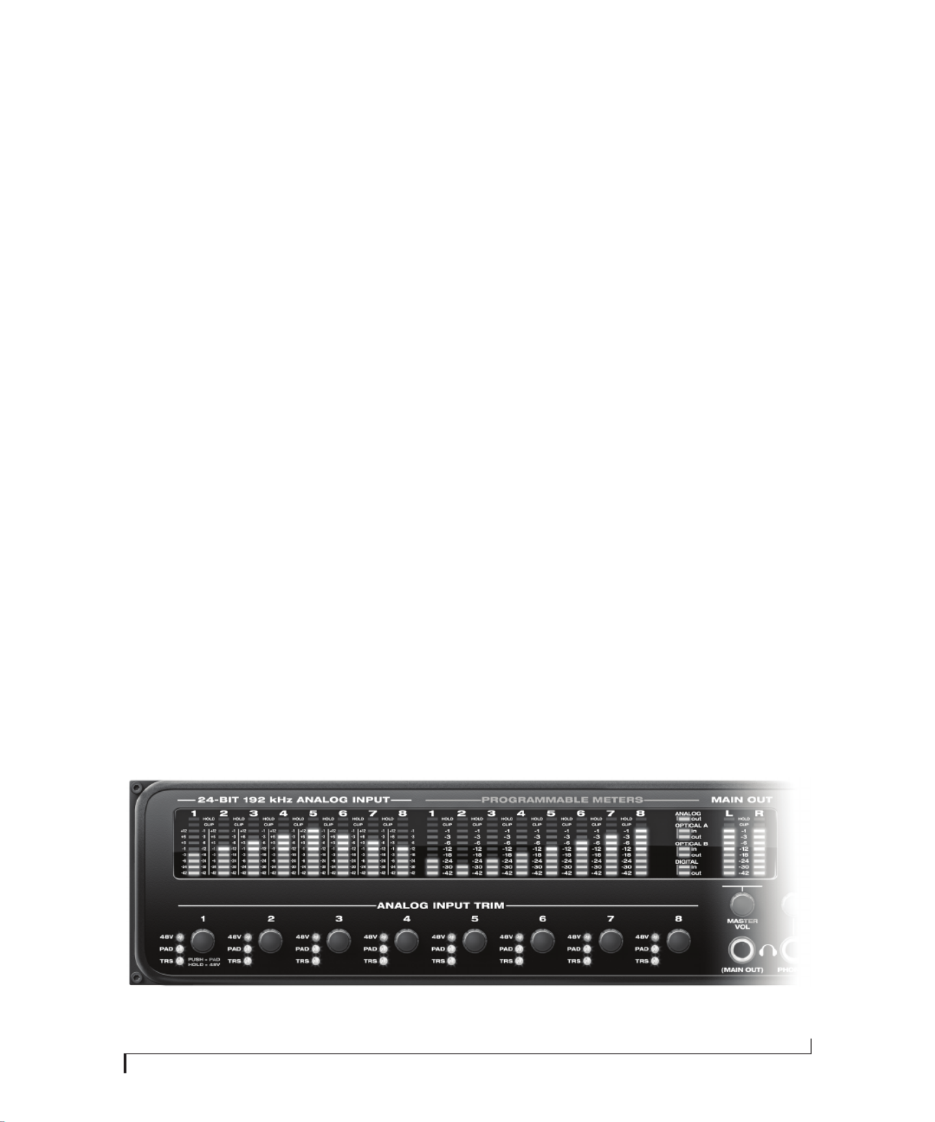
CHAPTER
47
6Front Panel Operation
OVERVIEW
The 896mk3 Hybrid offers complete front-panel
programming via six rotary encoders and a 2x16
backlit LCD display. All 896mk3 settings can be
accessed via these front-panel controls.
Analog input controls. . . . . . . . . . . . . . . . . . . . . . . . . . . . . . . . 47
Master vol and “(MAIN OUT)” phone jack . . . . . . . . . . . . 48
Phones. . . . . . . . . . . . . . . . . . . . . . . . . . . . . . . . . . . . . . . . . . . . . . . 48
Analog input meters with V-Limit™ compressor. . . . . 48
Programmable meters. . . . . . . . . . . . . . . . . . . . . . . . . . . . . . . 49
Push-button rotary encoders . . . . . . . . . . . . . . . . . . . . . . . . 49
Multi-function LCD display . . . . . . . . . . . . . . . . . . . . . . . . . . 49
896mk3 Setup menu . . . . . . . . . . . . . . . . . . . . . . . . . . . . . . . . 50
Audio menu . . . . . . . . . . . . . . . . . . . . . . . . . . . . . . . . . . . . . . . . . 51
CueMix menu. . . . . . . . . . . . . . . . . . . . . . . . . . . . . . . . . . . . . . . . 51
Inputs menu . . . . . . . . . . . . . . . . . . . . . . . . . . . . . . . . . . . . . . . . . 55
Outputs menu . . . . . . . . . . . . . . . . . . . . . . . . . . . . . . . . . . . . . . . 55
Mixes menu. . . . . . . . . . . . . . . . . . . . . . . . . . . . . . . . . . . . . . . . . . 56
Reverb menu . . . . . . . . . . . . . . . . . . . . . . . . . . . . . . . . . . . . . . . . 56
Stand-alone operation. . . . . . . . . . . . . . . . . . . . . . . . . . . . . . . 56
ANALOG INPUT CONTROLS
The 896mk3 front panel analog input controls
(Figure 6-1) allow you to work with a wide variety
of recording situations.
For information about connections and settings,
see “Analog inputs” on page 23 in the installation
chapter.
For information about the many settings available
for the mic/guitar inputs, see:
■“The Inputs tab” on page 77
■“The channel settings section” on page 81
■“The Channel tab” on page 82
■“The EQ tab” on page 84
■“The Dynamics tab” on page 91
Figure 6-1: The 896mk3 Hybrid front panel mic/instrument input controls.
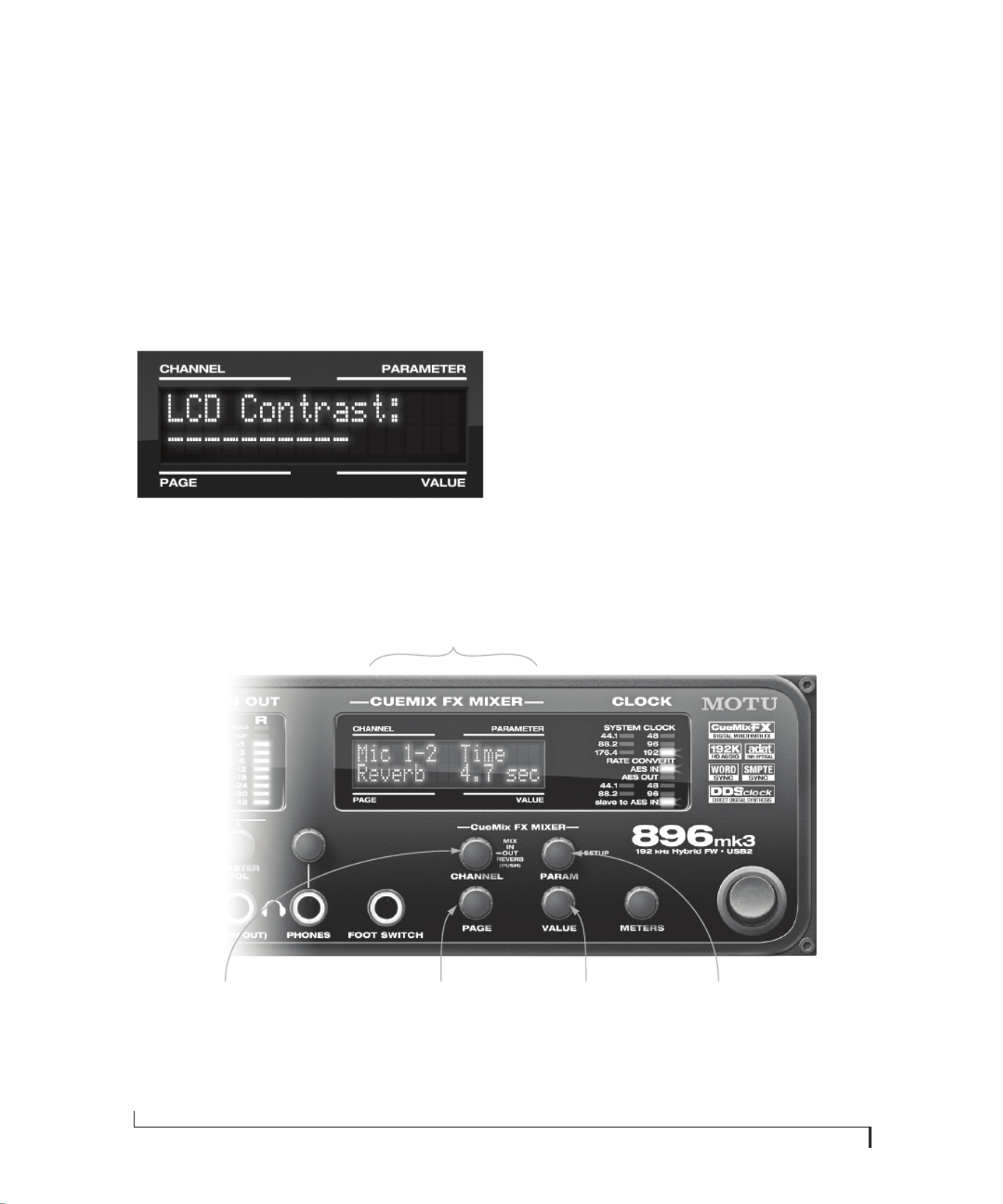
F R O N T P A N E L O P E R A T I O N
50
896MK3 SETUP MENU
To access the 896mk3 SETUP menu, push the
PARAM knob until you see 896mk3 SETUP
displayed in the LCD. This menu provides basic
features for managing the 896mk3 hardware. Turn
the PARAM knob to access each setting, explained
briefly below.
LCD Contrast
Turn the VALUE knob to adjust the LCD contrast.
Figure 6-8: In setup mode, the LCD displays a setup parameter in the
top row of the LCD and the current setting in the bottom row.
Save/Name Preset
An 896mk3 preset holds all current CueMix FX
mix settings (everything in the CUEMIX menu).
SETUP menu and AUDIO menu parameters are
not included. Turn the VALUE knob to move from
character to character in the preset name. Turn
PAGE to change the currently flashing letter. Once
you’ve named the preset, push VALUE to save it,
turn it again to choose the desired preset slot you
wish to save it to (1-16), and then push again to
confirm the save. Cancel the save operation at any
time by turning the PARAM knob.
Load Preset
Turn VALUE to choose the preset you wish to load
(1-16) and push VALUE to load it.
AutoSave Status
All of the parameters in the 896mk3 are
periodically saved automatically in its memory, so
that if you power down the unit, it will power back
Figure 6-6: The 896mk3 Hybrid front panel controls.
The LCD is divided into four
sections that correspond to the
four knobs below.
Push the PARAM knob to cycle
among three global menus:
CUEMIX (mixer), AUDIO
(settings) and 896mk3 SETUP.
When viewing CueMix settings in the
LCD, push the CHANNEL knob to cycle
among four main mixer menus: MIX,
IN (inputs), OUT (outputs) and
REVERB. Turn it to choose a channel.
Turn the PAGE knob to view settings for
each channel. Push it to jump to the
next section or back to the beginning.
Turn and/or push the
VALUE knob to adjust
the current setting.
Produktspecifikationer
| Varumärke: | Motu |
| Kategori: | DJ-utrustning |
| Modell: | 896Mk3 Hybrid |
Behöver du hjälp?
Om du behöver hjälp med Motu 896Mk3 Hybrid ställ en fråga nedan och andra användare kommer att svara dig
DJ-utrustning Motu Manualer

10 September 2024
10 September 2024
10 September 2024
9 September 2024
9 September 2024
9 September 2024
9 September 2024
9 September 2024
9 September 2024
9 September 2024
DJ-utrustning Manualer
- DJ-utrustning Kenwood
- DJ-utrustning Karcher
- DJ-utrustning Pioneer
- DJ-utrustning Yamaha
- DJ-utrustning Akai
- DJ-utrustning Alesis
- DJ-utrustning American Audio
- DJ-utrustning Arturia
- DJ-utrustning Silvercrest
- DJ-utrustning Thomson
- DJ-utrustning Lenco
- DJ-utrustning Pyle
- DJ-utrustning Sencor
- DJ-utrustning BeamZ
- DJ-utrustning Audio-Technica
- DJ-utrustning Gemini
- DJ-utrustning Denver
- DJ-utrustning Roland
- DJ-utrustning Brigmton
- DJ-utrustning Denon
- DJ-utrustning Sunstech
- DJ-utrustning Vonyx
- DJ-utrustning Thorens
- DJ-utrustning Korg
- DJ-utrustning Technisat
- DJ-utrustning Marquant
- DJ-utrustning Technics
- DJ-utrustning Fenton
- DJ-utrustning Krüger And Matz
- DJ-utrustning Allen & Heath
- DJ-utrustning Envivo
- DJ-utrustning Muse
- DJ-utrustning Bigben Interactive
- DJ-utrustning Pro-Ject
- DJ-utrustning Faderfox
- DJ-utrustning Ion
- DJ-utrustning Apogee
- DJ-utrustning Pyle Pro
- DJ-utrustning Behringer
- DJ-utrustning PreSonus
- DJ-utrustning Native Instruments
- DJ-utrustning Tascam
- DJ-utrustning Focusrite
- DJ-utrustning Festo
- DJ-utrustning Auna
- DJ-utrustning IK Multimedia
- DJ-utrustning EVO
- DJ-utrustning QTX
- DJ-utrustning Ricatech
- DJ-utrustning Konig
- DJ-utrustning Reloop
- DJ-utrustning Numark
- DJ-utrustning Teac
- DJ-utrustning Mpman
- DJ-utrustning Trevi
- DJ-utrustning Technaxx
- DJ-utrustning Swann
- DJ-utrustning Chauvet
- DJ-utrustning Nevir
- DJ-utrustning ESI
- DJ-utrustning Omnitronic
- DJ-utrustning Newstar
- DJ-utrustning Apart
- DJ-utrustning Saramonic
- DJ-utrustning Rode
- DJ-utrustning Line 6
- DJ-utrustning Cambridge
- DJ-utrustning Eurolite
- DJ-utrustning Audient
- DJ-utrustning Skytec
- DJ-utrustning M-Audio
- DJ-utrustning Beyerdynamic
- DJ-utrustning AudioQuest
- DJ-utrustning RME
- DJ-utrustning Atomix
- DJ-utrustning Konig & Meyer
- DJ-utrustning Stanton
- DJ-utrustning Power Dynamics
- DJ-utrustning Music Hall
- DJ-utrustning Citronic
- DJ-utrustning SPL
- DJ-utrustning Monacor
- DJ-utrustning Martin
- DJ-utrustning MWM
- DJ-utrustning Hercules
- DJ-utrustning DAP Audio
- DJ-utrustning Vocopro
- DJ-utrustning Suonobuono
- DJ-utrustning Universal Audio
- DJ-utrustning Formula Sound
- DJ-utrustning IConnectivity
- DJ-utrustning Ortofon
- DJ-utrustning Novation
- DJ-utrustning Serato
- DJ-utrustning Kenton
- DJ-utrustning Ecler
- DJ-utrustning Icon
- DJ-utrustning Fuzzix
- DJ-utrustning Gravity
- DJ-utrustning DB Technologies
- DJ-utrustning TC Helicon
- DJ-utrustning Fun Generation
- DJ-utrustning Cheetah
- DJ-utrustning ANT
- DJ-utrustning IMG Stage Line
- DJ-utrustning Denon DJ
- DJ-utrustning Sirus
- DJ-utrustning Rane
- DJ-utrustning Elektron
- DJ-utrustning Zomo
- DJ-utrustning Nektar
- DJ-utrustning Flexson
- DJ-utrustning Fluid
- DJ-utrustning Genki Instruments
- DJ-utrustning JTS
- DJ-utrustning Mixars
- DJ-utrustning Eliminator Lighting
- DJ-utrustning UDG Gear
- DJ-utrustning Pangea Audio
- DJ-utrustning Glorious
- DJ-utrustning Majestic
- DJ-utrustning Adam Hall
- DJ-utrustning Meris
- DJ-utrustning PLAYdifferently
- DJ-utrustning The T.mix
- DJ-utrustning MoFi
- DJ-utrustning Monkey Banana
- DJ-utrustning AlphaTheta
- DJ-utrustning Headliner
Nyaste DJ-utrustning Manualer
14 Mars 2025
5 Mars 2025
4 Mars 2025
9 Februari 2025
8 Februari 2025
7 Februari 2025
3 Februari 2025
31 Januari 2025
31 Januari 2025
27 Januari 2025