Sherwood R-872 Bruksanvisning
Sherwood
Ljud/videomottagare
R-872
Läs nedan 📖 manual på svenska för Sherwood R-872 (81 sidor) i kategorin Ljud/videomottagare. Denna guide var användbar för 17 personer och betygsatt med 4.5 stjärnor i genomsnitt av 2 användare
Sida 1/81

2
ENGLISH
Introduction
: TO REDUCE THE RISK OF FIRE OR ELECTRIC SHOCK,
DO NOT EXPOSE THIS APPLIANCE TO RAIN OR MOISTURE.
This symbol is intended to alert the user to the presence of
uninsulated "dangerous voltage" within the product's
enclosure that may be of sufficient magnitude to constitute
a risk of electric shock to persons.
This symbol is intended to alert the user to the presence of
important operating and maintenance (servicing)
instructions in the literature accompanying the appliance.
Caution regarding installation
Note : For heat dispersal, do not install this unit in a confined space such as a bookcase or similar enclosure.
: TO REDUCE THE RISK OF ELECTRIC
SHOCK, DO NOT REMOVE COVER (OR
BACK). NO USER-SERVICEABLE PARTS
INSIDE. REFER SERVICING TO
QUALIFIED SERVICE PERSONNEL.
CAUTION
WARNING
Units shipped to Australia are designed for operation on 240 V AC only.
To ensure safe operation, the three-pin plug supplied must be inserted only into a standard three-
pin power point which is effectively earthed through the normal household wiring. Extension cords
used with the equipment must be three-core and be correctly wired to provide connection to earth.
Improper extension cords are a major cause of fatalities. The fact that the equipment
operates satisfactorily does not imply that the power point is earthed and that the installation
is completely safe. For your safety, if in any doubt about the effective earthing of the power
point, consult a qualified electrician.
PAN-EUROPEAN UNIFIED VOLTAGE
All units are suitable for use on supplies 220-240 V AC.
FOR YOUR SAFETY
EUROPE
AUSTRALIA
220 V
-
240 V
Do not block ventilation openings or stack other equipment on the top.
READ THIS BEFORE OPERATING YOUR UNIT
CAUTION
• Leave a space around the unit for sufficient ventilation.
• Avoid installation in extremely hot or cold locations, or in an area
that is exposed to direct sunlight or heating equipment.
• Keep the unit free from moisture, water, and dust.
• Do not let foreign objects in the unit.
• The ventilation should not be impeded by covering the ventilation
openings with items, such as newspapers, table-cloths, curtains,
etc.
• No naked flame sources, such as lighted candles, should be
placed on the unit.
• Please be care the environmental aspects of battery disposal.
• The unit shall not be exposed to dripping or splashing for use.
• No objects filled with liquids, such as vases, shall be placed on
the unit.
• Do not let insecticides, benzene, and thinner come in contact
with the set.
• Never disassemble or modify the unit in any way.
Notes on the AC power cord and the wall outlet.
• The unit is not disconnected from the AC power source(mains)
as long as it is connected to the wall outlet, even if the unit has
been turned off.
• To completely disconnect this product from the mains,
disconnect the plug from the wall socket outlet.
• When setting up this product, make sure that the AC outlet you
are using is easily acceptable.
• Disconnect the plug from the wall outlet when not using the unit
for long periods of time.
Information for Users on Collection and Disposal of
Old Equipment and used Batteries
These symbols on the products, packaging, and/or
accompanying documents mean that used electrical and
electronic products and batteries should not be mixed
with general household waste. For proper treatment,
recovery and recycling of old products and used
batteries, please take them to applicable collection
points, in accordance with your national legislation.
By disposing of these products and batteries correctly,
you will help to save valuable resources and prevent any
potential negative effects on human health and the
environment which could otherwise arise from
inappropriate waste handling.
For more information about collection and recycling of
old products and batteries, please contact your local
municipality, your waste diposal service or the point of
sale where you purchased the items.
[Information on Disposal in other Countries outside the
European Union]
These symbols are only valid in the European Union. If
you wish to discard these items, please contact your
local authorities or dealer and ask for the correct method
of diposal.
Note for the battery symbol (bottom two symbol
examples):
The sign Pb below the symbol for batteries indicates that
this batteries contains lead.

ENGLISH
3
CONTENTS
• Introduction
READ THIS BEFORE OPERATING YOUR UNIT . . . . . . . . . . . . . . . . . . . . . . . . . . . . . . . 2
• System Connections . . . . . . . . . . . . . . . . . . . . . . . . . . . . . . . . . . . . . . . . . . . . . . . . . . . . . . . . . . 4
• Front Panel Controls . . . . . . . . . . . . . . . . . . . . . . . . . . . . . . . . . . . . . . . . . . . . . . . . . . . . . . . . . 15
• Universal Remote Controls . . . . . . . . . . . . . . . . . . . . . . . . . . . . . . . . . . . . . . . . . . . . . . . . . . . . 17
OPERATING COMPONENTS WITH REMOTE CONTROL . . . . . . . . . . . . . . . . . . . . . . 19
REMOTE CONTROL OPERATION RANGE . . . . . . . . . . . . . . . . . . . . . . . . . . . . . . . . . . 19
LOADING BATTERIES . . . . . . . . . . . . . . . . . . . . . . . . . . . . . . . . . . . . . . . . . . . . . . . . . . 19
USING FUNCTIONS OF REMOTE CONTROL . . . . . . . . . . . . . . . . . . . . . . . . . . . . . . . . 20
• ROOM 2 Remote Controls
REMOTE CONTROL OPERATION RANGE . . . . . . . . . . . . . . . . . . . . . . . . . . . . . . . . . . 28
LOADING BATTERY . . . . . . . . . . . . . . . . . . . . . . . . . . . . . . . . . . . . . . . . . . . . . . . . . . . . 28
• Operations
LISTENING TO A PROGRAM SOURCE . . . . . . . . . . . . . . . . . . . . . . . . . . . . . . . . . . . . . 29
SURROUND SOUND . . . . . . . . . . . . . . . . . . . . . . . . . . . . . . . . . . . . . . . . . . . . . . . . . . . . 32
ENJOYING SURROUND SOUND . . . . . . . . . . . . . . . . . . . . . . . . . . . . . . . . . . . . . . . . . . 34
LISTENING TO RADIO BROADCASTS . . . . . . . . . . . . . . . . . . . . . . . . . . . . . . . . . . . . . 38
LISTENING TO RDS BROADCASTS(FM ONLY) . . . . . . . . . . . . . . . . . . . . . . . . . . . . . . 40
(RDS Tuner(Regional Option for some countries in Europe, etc.))
RECORDING . . . . . . . . . . . . . . . . . . . . . . . . . . . . . . . . . . . . . . . . . . . . . . . . . . . . . . . . . . 42
DIGITAL AUDIO RECORDING WITH MD RECORDER . . . . . . . . . . . . . . . . . . . . . . . . . 43
OTHER FUNCTIONS . . . . . . . . . . . . . . . . . . . . . . . . . . . . . . . . . . . . . . . . . . . . . . . . . . . . 44
ROOM 2 SOURCE PLAYBACK . . . . . . . . . . . . . . . . . . . . . . . . . . . . . . . . . . . . . . . . . . . . 45
• OSD Menu Settings . . . . . . . . . . . . . . . . . . . . . . . . . . . . . . . . . . . . . . . . . . . . . . . . . . . . . . . . . . . 47
SETTING THE SYSTEM SETUP . . . . . . . . . . . . . . . . . . . . . . . . . . . . . . . . . . . . . . . . . . . 49
SETTING THE INPUT SETUP . . . . . . . . . . . . . . . . . . . . . . . . . . . . . . . . . . . . . . . . . . . . . 53
SETTING THE SPEAKER / ROOM EQ SETUP . . . . . . . . . . . . . . . . . . . . . . . . . . . . . . . 58
SETTING THE CH LEVEL SETUP . . . . . . . . . . . . . . . . . . . . . . . . . . . . . . . . . . . . . . . . . 64
SETTING THE SOUND PARAMETER . . . . . . . . . . . . . . . . . . . . . . . . . . . . . . . . . . . . . . 66
SETTING THE MULTI ROOM SETUP . . . . . . . . . . . . . . . . . . . . . . . . . . . . . . . . . . . . . . . 70
• Troubleshooting Guide . . . . . . . . . . . . . . . . . . . . . . . . . . . . . . . . . . . . . . . . . . . . . . . . . . . . . . . 72
• Specifications . . . . . . . . . . . . . . . . . . . . . . . . . . . . . . . . . . . . . . . . . . . . . . . . . . . . . . . . . . . . . . . 73
• Setup Code Table . . . . . . . . . . . . . . . . . . . . . . . . . . . . . . . . . . . . . . . . . . . . . . . . . . . . . . . . . . . . 74
4
ENGLISH
1
310911 2 12
54 6 8 8 7 8 13
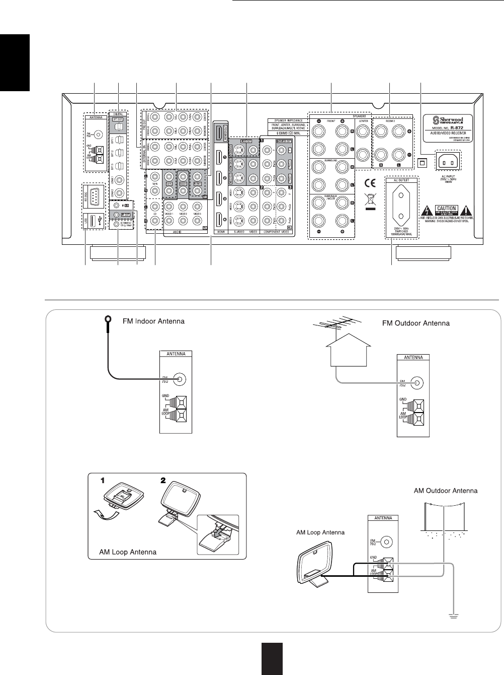
System Connections
• Please be certain that this unit is unplugged from the AC outlet before making any connections.
• Since different components often have different terminal names, carefully read the operating instructions of the
component connected.
• Be sure to observe the color coding when connecting audio, video and speaker cords.
• Make connections firmly and correctly. If not, it can cause loss of sound, noise or damage to the receiver.
• Change the position of the FM indoor antenna
until you get the best reception of your favorite
FM stations.
• Place the AM loop antenna as far as possible from the
receiver, TV set, speaker cords and the AC input cord
and set it to a direction for the best reception.
• If the reception is poor with the AM loop antenna, an
AM outdoor antenna can be used in place of the AM
loop antenna.
• A 75Ωoutdoor FM antenna may be used to fur-
ther improve the reception. Disconnect the
indoor antenna before replacing it with the out-
door one.
1. CONNECTING ANTENNAS

HDMI (High Definition Multimedia Interface) connection : (*1)
• You can connect the source component (DVD player, etc.) to the
display component (TV, projector, etc.) through this receiver with
using a commercially available HDMI cord.
• The HDMI connection can carry uncompressed digital video signals
and digital audio signals.
• The HDMI video stream signals (video signals) are theoretically
compatible with DVI-D. When connecting to a TV monitor, etc.,
equipped with DVI-D connector, it is possible to connect using a
commercially available HDMI-DVI converter cord.
Since the HDMI-to-DVI connection cannot carry any audio signals,
you should make audio connections to play the audio signals on the
component equipped with DVI-D connector. (For details, refer to the
operating instructions of its.)
• If you connect the HDMI INs to your video components, it is easier to do so
following the default settings.
• If your HDMI connection is different from the default setting, you should assign the HDMI INs
you used with the "When selecting the HDMI ASSIGN" procedure on page 54.
• The default settings are as follows :
HDMI 1 : VIDEO 1, HDMI 2 : VIDEO 2, HDMI 3 : VIDEO 3, HDMI 4 : VIDEO 4
Copyright protection system
• This unit supports HDCP (High-bandwidth Digital Contents Protection), technology to protect copyright of
digital video signals against illegal duplication. HDCP must also be supported on the components connected
to this unit.
• This unit is HDMI Ver. 1.3 compatible.
• HDMI, the HDMI logo and High-Definition Multimedia Interface are trademarks or registered trademarks of
HDMI licensing LLC.
5
ENGLISH
• The jacks of VIDEO 1 may also be connected to a DVD recorder or other digital video recording
component. For details, refer to the operating instructions of the component to be connected.
• The jacks of VIDEO 2/VIDEO 3 can also be connected to an additional video component such as a cable
TV tuner or satellite system.
• Connect the jacks of VIDEO 3 to the video component in the same way.
2. CONNECTING VIDEO COMPONENTS
ENGLISH
6
Notes :
• For stable signal transfer, we recommend using HDMI cords that are a maximum of 5 meters in length.
• Among the components that support HDMI, some components can control other components via the HDMI
connector. However, this unit cannot be controlled by another component via the HDMI connector.
• The audio signals from the HDMI connector (including the sampling frequency and bit length) may be limited by
the component that is connected.
• The video signals will not be output properly if a component incompatible with HDCP is connected.
• If the resolutions of the video signals which are output from the MONITOR OUTs and your monitor TV are not
matched, the picture is not clear, natural or displayed. In this case, change the setting of the resolution on either
this unit or the source component (DVD player, etc.) to one which the monitor TV can handle. (For details, refer
to "When selecting the VIDEO SCALING" on page 55 or the operating instructions of the source component.)
• When you want to enjoy only the picture on your TV, not the sound, you should set the HDMI AUDIO OUT to
OFF not to output the digital audio signal from the HDMI MONITOR OUT of this receiver. (For details, refer to
"When selecting the HDMI AUDIO OUT" on page 50.)
Component video input default settings: (*2)
• If you connect the COMPONENT VIDEO INs to your video components, it is easier to do so following the
default settings.
• If your component video connections are different from the default setting, you should assign the COMPONENT
VIDEO INs you used with the "When selecting the VIDEO ASSIGN" procedure on page 54.
• The default settings are as follows:
COMPONENT IN 1 : VIDEO 1, COMPONENT IN 2 : VIDEO 2, COMPONENT IN 3 : VIDEO 3
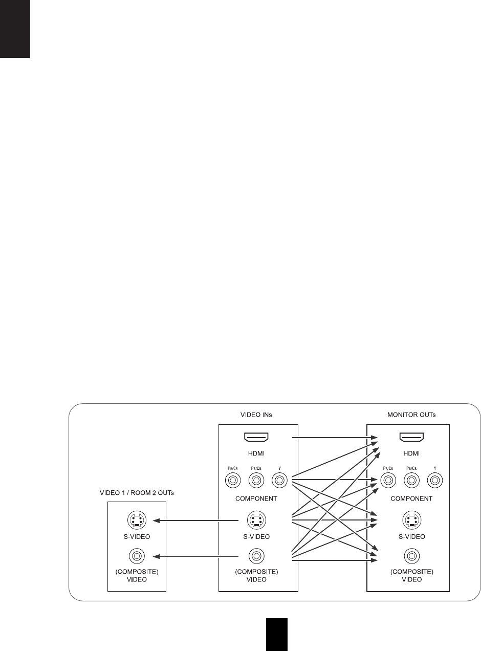
• There are three types of video jacks (COMPONENT, S-VIDEO, (composite) VIDEO) for analog video
connections and the HDMI connectors for digital video and audio connections.
Connect them to the corresponding video jacks according to their capability.
• For your reference, the excellence in picture quality is as follows : "HDMI” > "COMPONENT" > "S-VIDEO" >
"(composite) VIDEO" .
• When making COMPONENT VIDEO connections, connect "Y" to "Y", "PB/CB" to "CB"(or "B-Y", "PB") and
"PR/CR" to "CR"(or "R-Y", "PR").
• When recording video program sources through VIDEO 1 OUT jacks or viewing ROOM 2 source through
ROOM 2 OUT jacks, you must use the same type of video jacks that you did connect to video playback
components such as DVD player, cable TV tuner, etc.
Video conversion
• This unit is equipped with a function that up-converts the video signals to the higher quality video signals and
down-converts the video signals to the lower quality video signals and outputs them from the MONITOR OUTs.
• Because of this, the MONITOR OUT jack(s) can be connected to the monitor TV with a set of cord(s) offering a
higher quality, regardless of how to make video connections between this unit and video playback components.
• After connecting the video components, you should set the VIDEO MODE correctly to output the video signals
from the connected MONITOR OUT(s). (For details, refer to "When selecting the VIDEO MODE" on page 54.)
The flow of the video signals
Continued
ENGLISH
7
Notes :
• When the VIDEO MODE is set to "AUTO" or "HDMI", if the 576i ~ 1080i video signals are input into the HDMI
IN connector, the HDMI video signals are output from the HDMI MONITOR OUT only.
• When the VIDEO MODE is set to "AUTO" or "COMPONENT" and no video signals are input into the HDMI IN,
if 576i video signals are input into the COMPONENT INs, the component video signals are output from the
MONITOR OUTs.
However, if 576p ~ 1080i video signals are input, the component video signals are output from the
COMPONENT and the HDMI MONITOR OUTs.
• When the VIDEO MODE is set to "AUTO", "HDMI" or "COMPONENT", if 1080p video signals are input into
the HDMI IN or the COMPONENT INs, no video signals will be output from the HDMI or the COMPONENT
MONITOR OUTs regardless of VIDEO SCALING setting.
• When the component video signals or the HDMI video signals are input and these signals are output from the
MONITOR OUTs, the momentary OSD cannot be displayed.
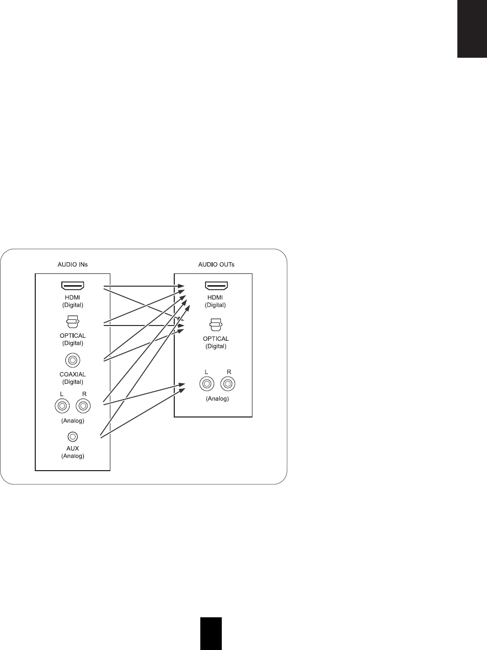
Audio conversion
• Depending on the AUDIO MODE setting, this unit can convert the analog audio signals (which are input into
the (analog) AUDIO INs) or the digital audio signals (which are input into the OPTICAL or the COAXIAL
DIGITAL IN) to the PCM 2 channel signals and output them from the HDMI MONITOR OUT. (For details,
refer to "When selecting the AUDIO MODE" on page 55.)
• The digital audio signals (which are input into the HDMI IN, the OPTICAL or the COAXIAL DIGITAL IN) can
be output from the OPTICAL DIGITAL OUT.
However, depending on the digital audio signal format input into the HDMI IN, some digital
signals cannot be output from the OPTICAL DIGITAL OUT.
The flow of the audio signals
Continued
Note :
• The analog audio signals which are input from the EXTERNAL INs cannot be output from any AUDIO OUTs.

8
ENGLISH
• The TAPE IN/OUT jacks can be connected to audio recording equipment such as a tape deck, an MD
recorder, etc.
• Use these jacks to connect the corresponding
outputs of a DVD player or external decoder,
etc. that has 6, 7 or 8 channel analog audio
outputs.
• In case of 6 or 7 channel outputs, do not connect
both of the SURROUND BACK L and R inputs or
the SURROUND BACK R input of this unit. (For
details, refer to the operating instructions of the
component to be connected.)
3. CONNECTING AUDIO COMPONENTS
4. CONNECTING EXTERNAL INS

ENGLISH
10
• Be sure to connect speakers firmly and
correctly according to the channel(left and
right) and the polarity (+ and -). If the
connections are faulty, no sound will be
heard from the speakers, and if the polarity
of the speaker connection is incorrect, the
sound will be unnatural and lack bass.
• For installing the speakers, refer to "Speaker
placement" on page 11.
• After installing the speakers, first adjust the
speaker settings according to your
environment and speaker layout. (For
details, refer to "SETTING THE SPEAKER
/ROOM EQ SETUP" on page 58.)
Surround back speakers
• When using only one surround back
speaker, you should connect it to
SURROUND BACK/MULTI LEFT channel.
• Because this receiver cannot drive the
surround back speakers and the ROOM 2
speakers simultaneously, you should assign
their power amplifier correctly depending on
how to use them. (For details, refer to
"CONNECTING ROOM 2 OUTS" on page
12 and "When selecting the AMP ASSIGN"
on page 49.)
Front Bi-Amp Connections.
• Some speakers are equipped with two sets
of input terminals, for bi-amplification.
• If no other surround back speakers are
used, you can connect the FRONT and the
SURROUND BACK/MULTI channels to the
bi-amp-capable speakers. (For details, refer
to the operating instructions of your bi-amp-
capable speakers.)
• To drive the bi-amp-capable speakers, you
should assign the power amplifier to "BI-
AMP".
Note :
• Before making bi-amp connections, remove
the short-circuiting bars from the terminals of
your speakers.
Caution :
• Be sure to use the speakers with the
impedance of 6 ohms or above.
• Do not let the bare speaker wires touch each
other or any metal part of this unit. This
could damage this unit and/or the speakers.
7. CONNECTING SPEAKERS

11
Ideal speaker placement varies depending on the
size of your room and the wall coverings, etc. The
typical example of speaker placement and
recommendations are as follows :
■Front left and right speakers and center speaker
• Place the front speakers with their front surfaces as
flush with TV or monitor screen as possible.
• Place the center speaker between the front left and
right speakers and no further from the listening
position than the front speakers.
• Place each speaker so that sound is aimed at the
location of the listener’s ears when at the main
listening position.
■Surround left and right speakers
• Place the surround speakers approximately 1 meter
(40 inches) above the ear level of a seated listener
on the direct left and right of them or slightly behind.
■Surround back left and right speakers
• Place the surround back speakers at the back facing
the front at a narrower distance than front speakers.
• When using a single surround back speaker, place it
at the rear center facing the front at a slightly higher
position (0 to 20 cm ) than the surround speakers.
• We recommend installing the surround back
speaker(s) at a slightly downward facing angle. This
effectively prevents the surround back channel
signals from reflecting off the TV or screen at the
front center, resulting in interference and making the
sense of movement from the front to the back less
sharp.
■Subwoofer
• The subwoofer reproduces powerful deep bass
sounds.
Place a subwoofer anywhere in the front as desired.
■Notes :
•When using a conventional TV, to avoid interference with the TV picture, use only magnetically shielded front
left and right and center speakers.
•To obtain the best surround effects, the speakers except the subwoofer should be full range speakers.
ENGLISH
Speaker placement
1. TV or Screen
2. Front left speaker
3. Subwoofer
4. Center speaker
5. Front right speaker
6. Surround left speaker
7. Surround right speaker
8. Surround back left speaker
9. Surround back right speaker
10. Surround center speaker
11. Listening position

ENGLISH
12
• ROOM 2 playback feature allows you to play a different program source in another room as well as one
source in the main room at the same time.
• For ROOM 2 playback, connect the ROOM 2 OUT jacks to the amplifier, TV, etc. installed in another room, or
connect the ROOM 2 speaker terminals to the speakers.
• Because this receiver cannot drive the surround back speakers and the ROOM 2 speakers simultaneously,
you should assign their power amplifier correctly depending on how to use them. (For details, refer to "When
selecting the AMP ASSIGN" on page 49.)
Notes :
• To minimize hum or noise, use high quality connection cords.
• You cannot use the digital audio signal for ROOM 2 playback.
• Connect a component to DC TRIGGER OUT
jack that allows DC 12V to turn on when a
specific input source is selected.
• For details, refer to the operating instructions
of the components to be connected.
• To link DC TRIGGER OUT with a specific
input source, refer to "When selecting the DC
TRIGGER" on page 56.
Notes :
• This output voltage (12V d.c., 100mA) is for (status) control only, it is not sufficient for drive capability.
• When making DC TRIGGER connection, you should use the stereo mini cord, not a mono mini cord.
or
8. CONNECTING ROOM 2 OUTS
9. CONNECTING DC TRIGGER OUT
13
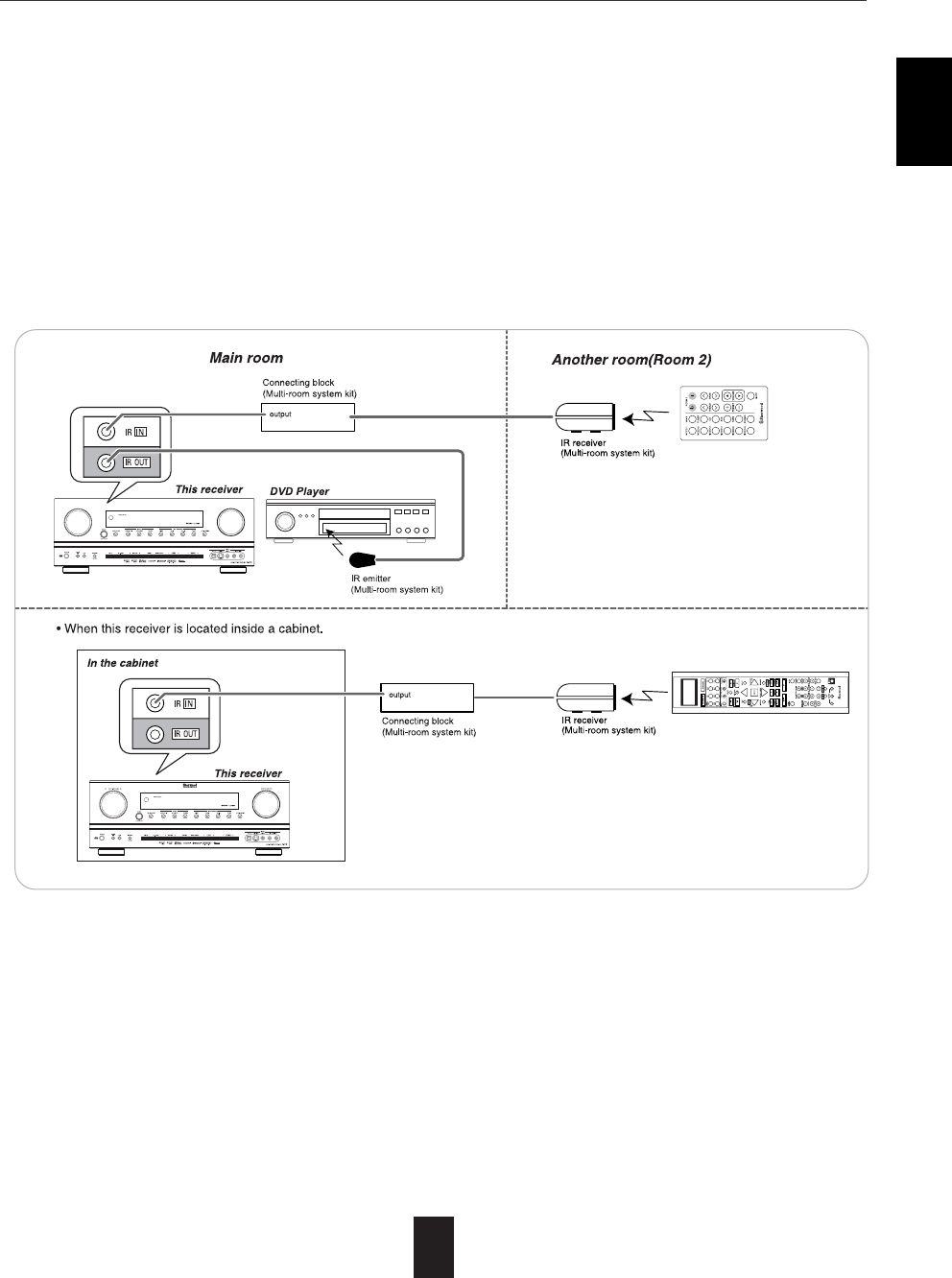
• The multi-room system kit(sold separately ) is essential for operation from a remote location .
For information on the multi-room system kit, contact the Xantech corporation at 1-800-843-5465 or
www.xantech.com.
• IR IN jack allows you to control this receiver from another room with the remote control unit.
• To control this receiver from another room with the remote control unit, connect the IR IN jack to the output of
the connecting block.
• If this receiver is located inside a cabinet or other enclosure where the infrared beams from the remote control
unit cannot enter, then operation with the remote control unit will not be possible. In such a case, connect the
IR IN jack to the output of the connecting block.
• To control other compatible component from another room with the universal remote control unit, connect the
IR OUT jack to the IR emitter.
Note:
• Remote operation may become unreliable if the IR receiver is exposed to strong light such as direct sunlight or
inverted fluorescent.
ENGLISH
10. CONNECTING MULTI-ROOM SYSTEM KIT

ENGLISH
14
Standby mode - Switched AC outlet off
Power - on mode - Switched AC outlet on
12. SWITCHED AC OUTLET
13. AC INPUT
• This outlet is switched on (power-on mode) and off
(standby mode) according to power control as
follows (Maximum total capacity is 100 W (0.43A)).
• Plug the supplied AC input cord into this AC inlet
and then into the wall AC outlet.
Note:
• Do not use an AC input cord other than the one
supplied with this unit. The AC input cord
supplied is designed for use with this unit and
should not be used with any other device.
• This receiver incorporates USB as well as RS-232C
terminal that may be used in the future to update the
operating software so that it will be able to support
new digital audio formats, external control by using an
external device and the like.
• Connect either USB or RS-232C terminal to your PC
(you don't need to do both).
Notes:
• Programming for upgrades and external control requires specialized programming knowledge and for that
reason we recommend that it only be done by qualified installers. For more information on future upgrades
and external control, visit the Sherwood web site at www.sherwoodamerica.com or contact your dealer.
• Do not disconnect the connection cable while updating the operating software, etc.
Should this happen, it may be result in malfunction or cause damage to the unit.
11. CONNECTING PC FOR UPGRADES

ENGLISH
15
Front Panel Controls
1. POWER switch
2. POWER ON/STANDBY button/indicator
3. VIDEO INPUT SELECTOR button
4. AUDIO INPUT SELECTOR button
5. EXTERNAL IN button
6. TUNER button
7. AUDIO ASSIGN button
8. MASTER VOLUME CONTROL knob
9. HEADPHONE jack
10. SPEAKER button
11. PURE AUDIO button
12. SURROUND MODE button
13. STEREO button
14. SETUP button
15. CHANNEL LEVEL button
16. CONTROL UP(▲)/DOWN(▼) buttons
17. ROOM 2 button
18. MEMORY/ENTER button
19. TUNING UP(+)/DOWN(-) buttons
20. PRESET UP(+)/DOWN(-) buttons
21. MULTI CONTROL knob
22. REMOTE SENSOR
23. PURE AUDIO indicator
24. FLUORESCENT DISPLAY
For details, see below.
25. SETUP MIC jack
For details, see next page.
26. AUX IN jack
For details, see next page.
27. VIDEO 4 IN jacks
For details, see next page.
FLUORESCENT DISPLAY
21201345671 8 910 111216141513171819
2
1. Dolby surround mode indicators
2. Auto surround indicator
3. Speaker(/channel output : outer box) indicators
4. Input signal indicators
5. REMASTERING indicator
6. HDMI indicator
7. ROOM 2 amp indicators
8. ROOM-EQ indicator
9. Input, frequency, surround mode, operating information, etc.
10. DIGITAL INPUT indicator
11. TONE indicator
12. SLEEP indicator
13. CINEMA EQ indicator
14. STEREO indicator
15. RDS indicators
16. MEMORY indicator
17. TUNED indicator
18. MUTE indicator
19. Preset number, volume level, sleep time display
20. VIDEO UPSCALE indicator
21. SPEAKER indicator

ENGLISH
16
• The AUX IN jack can be connected to an additional
audio component such as an MP3 player, etc.
Note :
• When connecting this jack to an MP3 player, etc., you
should use the stereo mini cord, not a mono mini cord.
VIDEO 4 IN JACKS
• To use Auto Setup function, connect the supplied
microphone to the SETUP MIC jack.(For details, refer
to "When selecting the AUTO SETUP" on page 58.)
Notes:
• Because the microphone for Auto Setup is designed
for use with this receiver, do not use a microphone
other than the one supplied with this receiver.
• After you have completed the auto setup procedure,
disconnect the microphone.
SETUP MIC JACK
AUX IN JACK
• The VIDEO 4 input jacks may be also connected
to an additional video component such as a
camcorder, a video game player, etc.
• If the OPTICAL IN 4 is connected to the
component connected to VIDEO 4, it is easier to
do so following the default settings.(For details,
refer to "Digital input default settings" on page 9.)
• If the OPTICAL IN 4 connection is different from
the default settings, you should assign the
DIGITAL INs you used with the "When selecting
the AUDIO ASSIGN" procedure on page 54.
• If you connect the COMPONENT VIDEO INs on
the rear panel to your video component, you
should assign the COMPONENT VIDEO INs you
used with the "When selecting the VIDEO
ASSIGN" procedure on page 54.
• If you connect the HDMI INs on the rear panel to
your video component, you should assign the
HDMI INs you used with the "When selecting the
HDMI ASSIGN" procedure on page 54.
When not using
the VIDEO 4 IN
jacks, cover these
jacks with the
supplied cap.

ENGLISH
17
Universal Remote Controls
This universal remote control can operate not only this receiver but also most popular brands of audio and video
components such as CD players, tape decks, TVs, cable boxes, VCRs, satellite receivers, DVD players, etc.
• To operate 7 components other than this receiver, you should enter the setup code for each component.
(For details, refer to "USING FUNCTIONS OF REMOTE CONTROL" on page 20.)
• The numbered buttons on the remote control have different functions in different device modes. For details,
refer to "FUNCTION TABLE of the NUMBERED BUTTONS" on the next page.
Note :
• In such a case that some components do not have the REMOTE SENSOR which receives the remote signals,
this remote control cannot operate them.

ENGLISH
18
FUNCTION TABLE of the NUMBERED BUTTONS.
Notes :
• Some functions for each component may not be available or may work differently.
• Depending on other kinds of components that are available for each DEVICE button, some functions may not be
available or may work differently, too.
• For details about functions, refer to the operating instructions of each component.
ENGLISH
19
LOADING BATTERIES
OPERATING COMPONENTS WITH REMOTE CONTROL
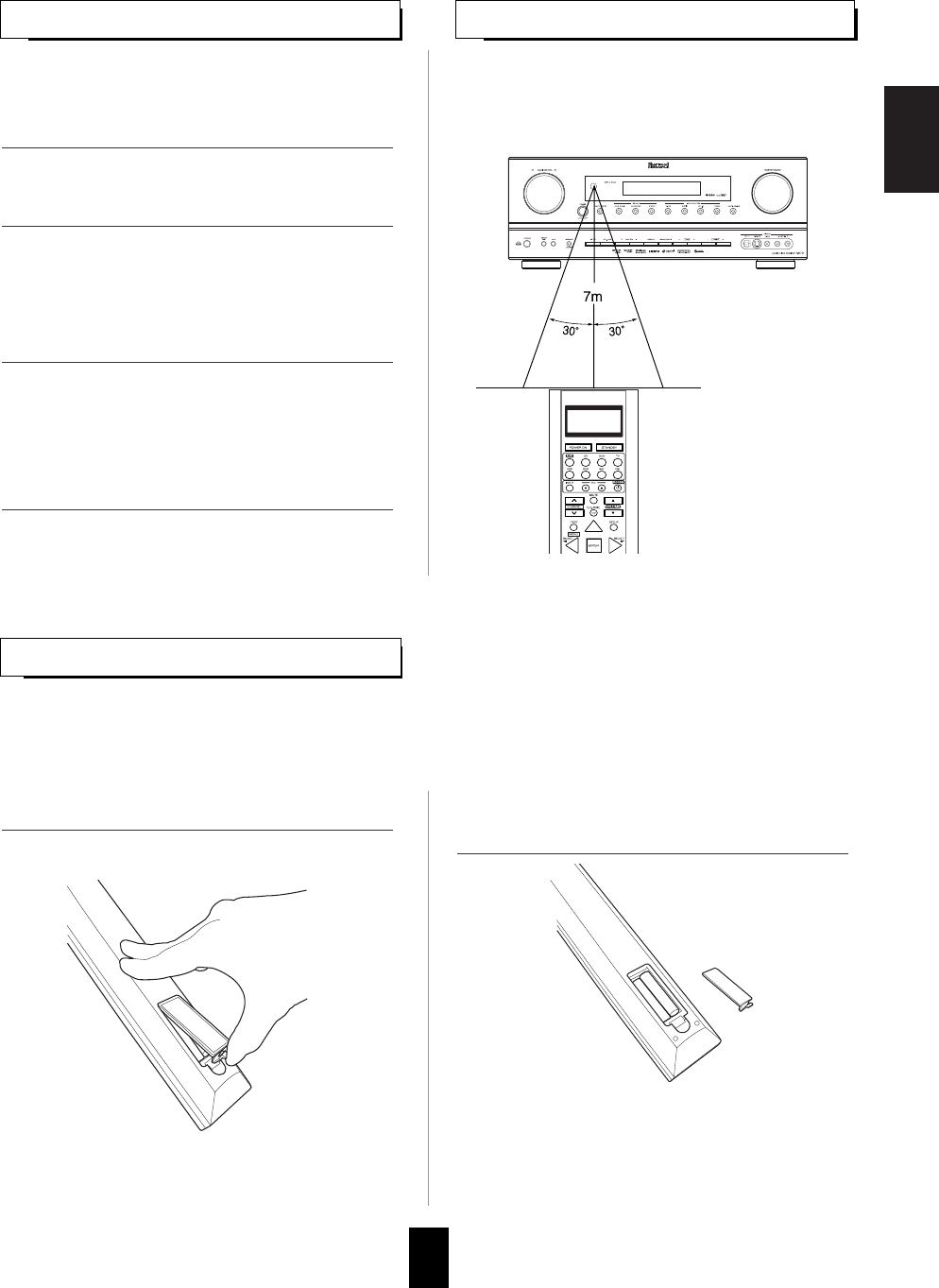
REMOTE CONTROL OPERATION RANGE
• Use the remote control within a range of about 7
meters (23 feet) and angles of up to 30 degrees
aiming at the remote sensor.
•When the remote control does not operate, the old batteries should be replaced. In this case, load new batteries
within several minutes after removing old batteries.
•If the batteries are removed or have been exhausted for a longer period of time, memorized contents will be
cleared. Should this happen, you should memorize them again.
+
+
+
• Remove the batteries when they are not used
for a long time.
• Do not use the rechargeable batteries (Ni-Cd
type).
• Be sure to use alkaline batteries.
1. Enter the setup code for each component other
than this receiver. For details, refer to "Entering
a setup code" on page 20.
2. Turn on the component you want to operate.
1. Remove the cover. 2. Load four alkaline batteries ("AAA" size, 1.5V)
matching the polarity.
3. Press the DEVICE button on the remote control
corresponding to the component you wish to
operate.
4. Aim the remote control at the REMOTE
SENSOR of the component you wish to control
and press the button corresponding to the
operation you want.
20
USING FUNCTIONS OF REMOTE CONTROL
Entering a setup code
• This remote control can control up to 8 different components.
• Before operating audio and video components other than this receiver with using this remote control, the
setup code for each component should be entered.
• For system remote control operation, "000" was stored previously in the memory of the device button "CD" for
Sherwood CD player, "DVD" for Sherwood DVD player, "AUX" for Sherwood tape deck and "TV" for Sherwood TV
respectively as its factory setup code. So, you don’t need to enter its code for each Sherwood component except
in such a case that its code does not work.
• Then "LEARN" is displayed on the LCD screen for
several seconds.
Notes :
• The AUDIO button is unavailable for the audio
components other than this receiver.
• During setting operation, to exit from the setting
mode, press any of the DEVICE buttons.
• Setup code entry is the easiest way to program
this remote control for operating audio and video
components.
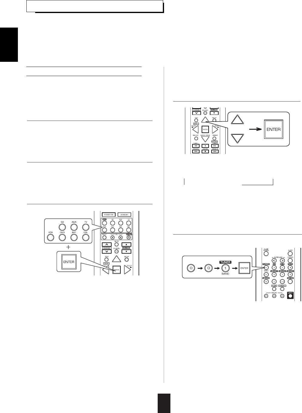
1. Turn on the component you want to operate.
2. Find the setup codes according to the type and
the brand name of your component, referring to
"Setup Code Table" on page 74.
3. Press and hold down both the ENTER button
and the desired one of the DEVICE buttons for
more than 2 seconds.
4. While "LEARN" is displayed, press the CURSOR
UP(▲)/DOWN(▼) buttons to select the setup
code mode ("CODE"), then press the ENTER
button.
5. While "PRESET", etc. are displayed, enter a 3
digit code and press the ENTER button.
ENGLISH
• Each time the CURSOR UP(▲)/DOWN(▼)
buttons are pressed, the mode changes as
follows :
LEARN DELETE MACRO
CODE PUNCH
• Then "PRESET" and 3 digit number are
displayed.
• If "PRESET", etc. go off, start again from the
above step 3.
Example: When entering "001".
• Then "OK" is displayed on the LCD screen.
• To be sure that the setup code is correct, press
the POWER ON (or STANDBY) button, aiming
the remote sensor on the component.
• If the setup code is correct, your component will
be turned off.
• When your component is not turned off, repeat
the above steps 2 to 5, trying entering each code
for your component until you find one that works.
• If "NG" is displayed, retry entering the correct
setup code while "PRESET" and 3 digit number
are displayed.

ENGLISH
21
ENGLISH
• If any of buttons fails to operate as they should,
start from the step 1again to enter the correct setup
code.
Note :
• Manufacturers may use different setup codes for
the same product category. For that reason, it is
important that you check to see if the code you
have entered operates as many controls as
possible. If only a few functions operate, check to
see if another code will work with more buttons.
6. Operate the component using the corresponding
function buttons.
4. While "PRESET" is displayed, press the ENTER
button to store the setup code.
5. Operate the component using the corresponding
function buttons.
6. Repeat the above steps 1 to 5 for each of your
other components.
1. Turn on the component you want to operate.
2. Perform the steps 3 and 4 in "Entering a setup
code" procedure on page 20 to select the setup
code mode ("CODE").
3. While "PRESET" is displayed, search a setup
code, aiming the remote control at the remote
sensor on the component.
7. Repeat the above steps 1 to 6 for each of your
other components.
Searching a setup code
• Each time the CURSOR UP(▲)/DOWN(▼)
buttons are pressed, the setup code is selected
one by one.
• If the selected code is correct, your component
will be turned off.
• When your component is not turned off, repeat
this step until you find one that works.
• In addition to enter a setup code using "Setup
Code Table" on page 74, it is also possible to
search through all the codes that are stored in the
library of this remote control.
• Then "OK" is displayed on the LCD screen.
• If any of buttons fails to operate as they should,
start from the step 1 again to find the correct
setup code.
ENGLISH
22
• If the command has been learned successfully,
"OK" is displayed and then "SEL" is flickering.
• If "ERROR" is displayed and then "SEL" is
flickering, it means that for some reason the
command was not learned. In this case, repeat
the above steps 4 and 5.
Notes :
• If an incorrect signal has been sent or, in some
cases, the command from other remote control
simply cannot be learned.
• In some "ERROR" cases, the remote controls just
need to be moved closer together or farther
apart.
Programming the commands from other
remote controls (LEARNING mode)
• Then "SEL" is flickering.
• If "SEL" goes off, start again from the above
step 2.
• If the setup codes are not available for your
component or you want to program a missing or
special function into one button of a device, the
learning function enables this remote control to
learn the commands from other remote controls.
• Then "READY" is displayed.
Note:
• You cannot program a function into some buttons
such as DEVICE, MACRO and LIGHT buttons.
To exit from the setting mode, press any of the
DEVICE buttons.
• Then "LEARN" is displayed on the LCD screen
for several seconds
Note :
• During setting operation, to exit from the setting
mode, press any of the DEVICE buttons.
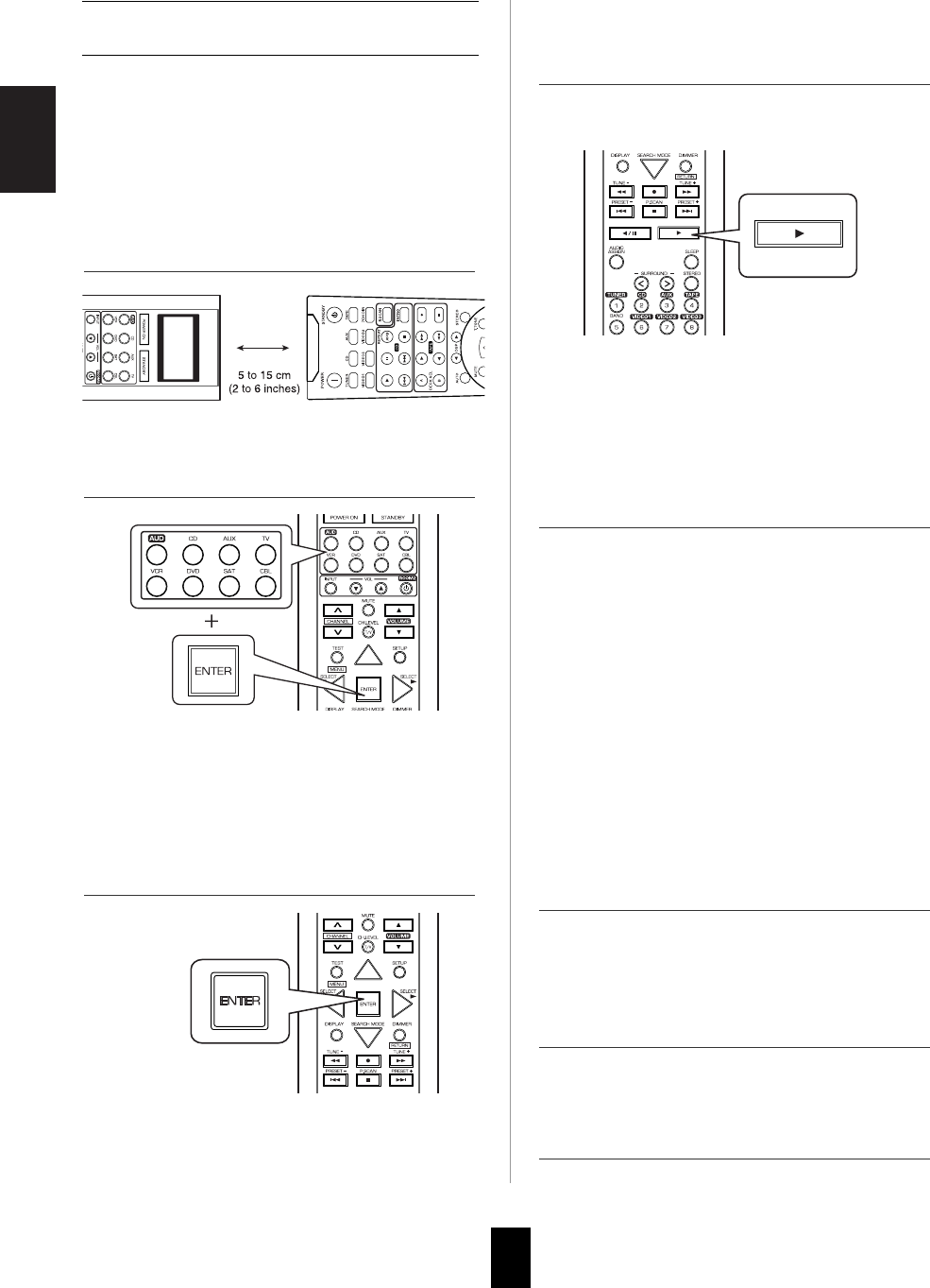
1. Place this remote control and other remote
control facing each other at a distance of 5 to 15
cm (2 to 6 inches ) apart.
2. Press and hold down the ENTER button and the
desired one of the DEVICE buttons for more
than 2 seconds.
3. While "LEARN" is displayed, press the ENTER
button.
4. While "SEL" is flickering, on this remote control,
press the button corresponding to the function to
be learned.
5. While "READY" is displayed, on the other
remote control, press the button of the function
to be learned.
8. Operate the newly programmed buttons to make
sure the learning function was performed
properly.
7. Repeat the above steps 1 to 6 to program the
commands from a different remote control.
6. While "SEL" is flickering, repeat the above steps
4 and 5 to program all the commands you want
to the buttons on this remote control under the
same device mode.
Example: If the function to be learned is playback,
press the PLAY(▶) button.

ENGLISH
23
Erasing the programmed command from
one button
• "OK" is displayed and then "SEL" is flickering.
• Then "BTTN" is displayed on the LCD screen for
several seconds.
Example: When the button for the command to be
erased is PLAY button.
• Each time the CURSOR UP(▲)/DOWN(▼)
buttons are pressed, "BTTN" or "LEARN"(all
command deleting mode) is selected.
• Then "SEL" is flickering.
• If "SEL" goes off, start again from the above
step 1.
1. Perform the steps 3 and 4 in "Entering a setup
code" procedure on page 20 to select the
deleting mode ("DELETE").
1. Perform the steps 3 and 4 in "Entering a setup
code" procedure on page 20 to select the
deleting mode ("DELETE").
2. While "BTTN" is displayed, press the CURSOR
UP(▲)/DOWN(▼) buttons to select the all
command deleting mode ("LEARN"), then press
the ENTER button.
3. While "SURE?" is displayed, press the ENTER
button.
4. To erase all the commands programmed under
other device mode, repeat the above steps 1 to
3.
2. While "BTTN" is displayed, press the CURSOR
UP(▲)/DOWN(▼) buttons to select the one
command deleting mode (BTTN), then press the
ENTER button.
3. While "SEL" is flickering, press the button for the
command you want to erase.
4. While "SEL" is flickering, repeat the above step
3 to erase other commands.
Erasing all the commands programmed
under a device mode
• Then all the commands programmed are erased.
• Then "BTTN" is displayed on the LCD screen for
several seconds.
• Then "SURE?" is displayed .
• If "SURE?" goes off, start again from the above
step 1.
24
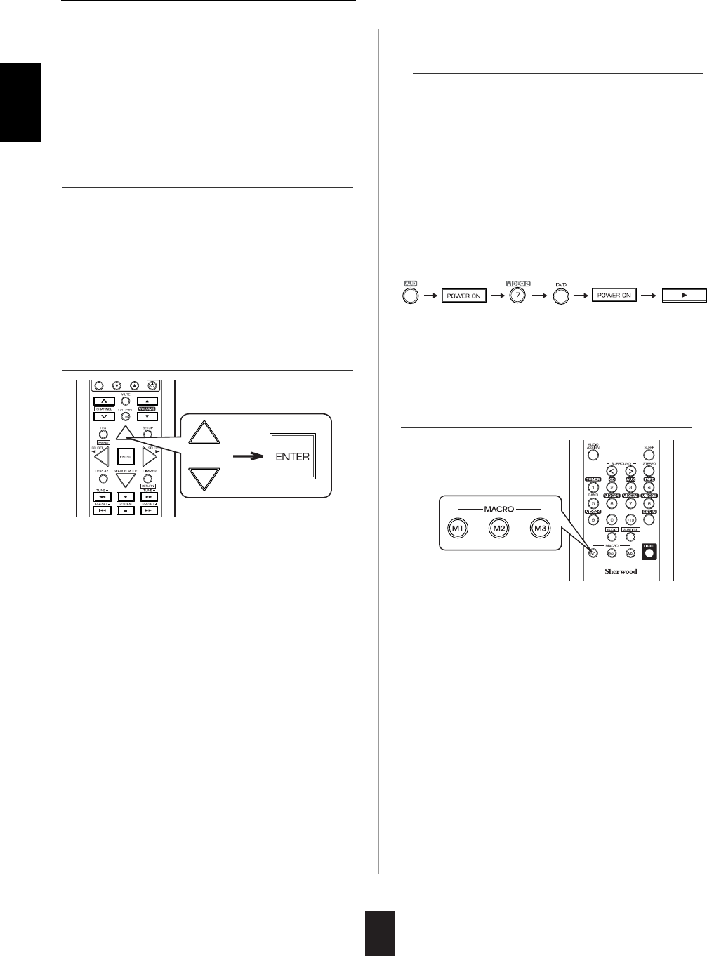
Programming a macro function
Example: When playing a DVD on the DVD player
connected to VIDEO 2 jacks of this
receiver.
①. Press "AUDIO" button to control this receiver.
②. Press "POWER ON" button to turn this
receiver on.
③. Press "VIDEO 2(7)" button to select the
desired input source.
④. Press "DVD" button to control the DVD player.
⑤. Press "POWER ON" button to turn the DVD
player on.
⑥. Press "PLAY (▶)" button to start playback.
• Each time the operation buttons are pressed, the
programmed order is displayed.
• The macro function enables you to program a
series of button operations(up to 15) on this
remote control into a single button.
• You can store up to three separate macro
command sequences into "M1", "M2" and "M3"
buttons.
• Then "M1" is displayed on the LCD screen for
several seconds.
• During macro setting operation, pressing any of
the DEVICE buttons cannot exit from the macro
mode.
• Each time the CURSOR UP(▲)/DOWN(▼)
buttons are pressed, "M1", "M2" or "M3" is
selected.
• Then "SEL" is flickering.
• If "SEL" goes off, start again from the above
step 1.
1. Perform the steps 3 and 4 in "Entering a setup
code" procedure on page 20 to select the macro
mode ("MACRO").
2. While "M1" is displayed, press the CURSOR
UP(▲)/DOWN(▼) buttons to select the MACRO
button to be programmed into, then press the
ENTER button.
3. While "SEL" is flickering, press the operation
buttons you want to program in order.
4. Press any of the MACRO buttons (M1~M3) to
complete the programming.
• Then "OK" is displayed.
To erase a macro program
• When erasing a macro program, perform the
above steps 1, 2 and 4, but ignore the step 3.
To change a macro program
• When a new macro program is stored into a
MACRO button with performing the above steps
1 to 4, the previous macro program is erased
from the memory of the MACRO button.
ENGLISH

25
Operating a macro function
Notes:
• The codes programmed into a MACRO button will
be transmitted at an interval of 0.5 seconds.
However, some components may not be able to
complete one operation in 0.5 seconds and may
miss the next code.
In this case, the macro function cannot control the
corresponding components correctly.
• Be sure to use the remote control within the remote
control operation range of the components.
• Depending on the operation status of the
components, etc., the macro function cannot
control the corresponding components correctly.
• Aim the remote control at the REMOTE
SENSORs of the components to be controlled
and press the MACRO button you want.
Example : When pressing "M1" button.
1. Perform the steps 3 and 4 in "Entering a setup
code" procedure on page 20 to select a master
device and the punch-through mode ("PUNCH").
2. While "VOL" is displayed, press the CURSOR
UP(▲)/DOWN(▼) buttons to select the desired
punch-through mode, then press the ENTER
button.
ENGLISH
Programming a punch-through function
• The punch-through function allows the volume
controls, channel controls or transport controls to
link to a different device while a device is
controlled with this remote control as a master
device.
• For example, since this receiver will likely be
used as the sound system while watching TV,
you may want to use volume controls to operate
this receiver although this remote control is set to
control the TV.
• Each time the CURSOR UP(▲)/DOWN(▼)
buttons are pressed, the mode changes as
follows:
→VOL : The volume punch -through mode
allows the "VOLUME ▲/▼" and
"MUTE" buttons to operate a different
device.
DELETE : All punch-through deleting mode.
PLAY : The transport punch-through mode
allows the "◀◀", "●", "▶▶", "
◀◀", "",
"▶▶
", "◀/
"and "▶" buttons to
operate a different device.
→CH : The channel punch-through mode
allows the "CHANNEL ∧/∨" and "CH.
LEVEL" buttons to operate a different
device.
• Then the device to which you can link the
selected punch-through mode is displayed.
• Then "VOL" is displayed on the LCD screen for
several seconds.

ENGLISH
26
• Each time the CURSOR UP(▲)/DOWN(▼)
buttons are pressed, depending on the selected
punch-through mode, punch-through devices
and the one punch-through deleting mode
("DELETE") are selected as follows :
• In case of the volume punch-through,
→AUDIO DELETE TV ←
• In case of the transport punch-through,
→CD DELETE DVD VCR AUX ←
• In case of the channel punch-through,
→TV DELETE SAT CABLE VCR ←
• Then "OK" is displayed and the current punch-
through mode is displayed.
3. While the device is displayed, press the
CURSOR UP(▲)/DOWN(▼) buttons to select
the desired punch-through device, then press
the ENTER button.
1. Perform the steps 3 and 4 in "Entering a setup
code" procedure on page 20 to select a master
device and the punch-through mode ("PUNCH").
2. While "VOL" is displayed, press the CURSOR
UP(▲)/DOWN(▼) buttons to select the punch-
through mode to be erased, then press the
ENTER button.
4. While the punch-through mode is displayed,
repeat the above steps 2 and 3 to program other
punch-through function under the same master
device mode.
5. To program punch-through functions under
other master device mode, repeat the above
steps 1 to 4.
Operating a punch-through function
• While this remote control is set to control a
master device, aim the remote control at the
REMOTE SENSOR of the punch-through device
and press the desired button of the programmed
punch-through controls.
Example: When pressing "PLAY (▶)" button.
• Then the punch-through device is displayed on
the LCD screen.
Erasing the programmed punch-through
function
• Then "VOL" is displayed on the LCD screen for
several seconds.
• Each time the CURSOR UP(▲)/DOWN(▼)
buttons are pressed, the mode changes as
follows:
→VOL DELETE PLAY CH ←
• Then the device is displayed .
Continued
Produktspecifikationer
| Varumärke: | Sherwood |
| Kategori: | Ljud/videomottagare |
| Modell: | R-872 |
| Färg på produkten: | Wit |
| Vikt: | 14500 g |
| Bredd: | 610 mm |
| Djup: | 365 mm |
| Höjd: | 205 mm |
| Förpackningens vikt: | 1700 g |
| Förpackningens bredd: | 710 mm |
| Djuppackning: | 470 mm |
| Förpackningshöjd: | 320 mm |
| Blåtand: | Nee |
| Anslutningsteknik: | Bedraad |
| Genomsnittlig effekt: | 200 W |
| Rekommenderad användning: | Universeel |
| Impedans: | 8 Ohm |
| Ljudutgångskanaler: | - kanalen |
| Bashögtalare: | Ja |
| Frekvensomfång: | 26 - 40000 Hz |
| Typ av högtalare: | 3-weg |
| Diameter högtonenhögtalare: | 25 mm |
| Antal diskantdrivrutiner: | 1 |
| Antal mellanklassförare: | 2 |
| Diameter förare i mellanregister: | 174 mm |
| Tweeter: | Ja |
| Crossover frekvens: | 3000 Hz |
| Högtalarposition: | Centrum |
Behöver du hjälp?
Om du behöver hjälp med Sherwood R-872 ställ en fråga nedan och andra användare kommer att svara dig
Ljud/videomottagare Sherwood Manualer

12 September 2024
9 September 2024
9 September 2024
9 September 2024
31 Augusti 2024
21 Augusti 2024
19 Augusti 2024
18 Augusti 2024
18 Augusti 2024
Ljud/videomottagare Manualer
- Ljud/videomottagare JVC
- Ljud/videomottagare Kenwood
- Ljud/videomottagare Onkyo
- Ljud/videomottagare Pioneer
- Ljud/videomottagare Yamaha
- Ljud/videomottagare Aiwa
- Ljud/videomottagare Harman Kardon
- Ljud/videomottagare Denon
- Ljud/videomottagare Marantz
- Ljud/videomottagare Icom
- Ljud/videomottagare Logilink
- Ljud/videomottagare Eltax
- Ljud/videomottagare Konig Electronic
- Ljud/videomottagare Focusrit
Nyaste Ljud/videomottagare Manualer
24 Oktober 2024
24 Oktober 2024
23 Oktober 2024
20 Oktober 2024
20 Oktober 2024
18 Oktober 2024
14 September 2024
14 September 2024
14 September 2024
14 September 2024