SRS DS335 Bruksanvisning
Läs nedan 📖 manual på svenska för SRS DS335 (86 sidor) i kategorin Generator. Denna guide var användbar för 5 personer och betygsatt med 4.5 stjärnor i genomsnitt av 2 användare
Sida 1/86

MODEL DS335
Synthesized Function Generator
1290-D Reamwood Avenue
Sunnyvale, California 94089
Phone: (408) 744-9040 • Fax: (408) 744-9049
email: info@thinkSRS.com • www.thinkSRS.com
Copyright © 1993, 2002, 2013 by SRS, Inc.
All Rights Reserved.
Revision 1.7 (11/2013)

DS335 Synthesized Function Generator

Table of Contents i
DS335 Synthesized Function Generator
Table of Contents
Condensed Information
Safety and Use iii
SRS Symbols iv
Specifications v
Abridged Command List ix
Getting Started
Introduction 1-1
CW Function Generation 1-1
Frequency Sweep 1-2
Operation
Introduction to DDS 2-1
DS335 Features 2-5
Front Panel Features 2-5
Rear Panel Features 2-7
Function Setting 2-9
Setting the Function 2-9
Frequency 2-9
Amplitude 2-9
DC Offset 2-11
Sweeps/FSK 2-13
Frequency Sweeps 2-13
Sweep Type 2-13
Sweep Frequencies 2-14
Sweep/FSK Output 2-14
FSK Intput 2-14
Instrument Setup 2-17
Default Settings 2-17
Store and Recall 2-17
GPIB and RS232 Setup 2-17
Self-Test 2-18
Programming
Programming the DS335 3-1
Communications 3-1
GPIB Communication 3-1
RS-232 Communication 3-1
Data Window 3-1
Command Syntax 3-1
Detailed Command List 3-2
Function Output Commands 3-3
Sweep Control 3-4
Setup Control Commands 3-6
Status Reporting Commands 3-6
Test and Calibration Commands 3-7
Status Byte Definitions 3-8
Programming Examples 3-11
Introduction 3-11
GPIB and C Example 3-12
RS232 and BASIC example 3-13
Test and Calibration
Troubleshooting 4-1
Operation Error Messages 4-1
Self-Test Error Messages 4-2
Performance Tests 4-5
Necessary Equipment 4-5
Functional Tests 4-6
Front Panel Test 4-6
Self Tests 4-6
Sine Wave 4-6
Square Wave 4-6
Amplitude Flatness 4-7
Output Level 4-7
Performance Tests 4-8
Frequency Accuracy 4-8
Amplitude Accuracy 4-8
DC Oset Accuracy 4-9
Subharmonics 4-9
Spurious Signals 4-10
Harmonic Distortion 4-10
Phase Noise 4-11
Square Wave Rise Time 4-11
Square Wave Symmetry 4-11
Test Scorecard 4-13
Calibration 4-15
Introduction 4-15
Calibration Enable 4-15
Calbytes 4-15
Necessary Equipment 4-19
Adjustments 4-19
Output Amplifier Bandwidth 4-19
Bessel Filter Adjustment 4-20

ii Table of Contents
DS335 Synthesized Function Generator
Calibration 4-20
Clock Calibration 4-20
DS335 Circuitry
Circuit Description 5-1
Front Panel Board 5-1
Main Board 5-1
Microprocessor System 5-1
Display and Keyboard 5-2
System DAC and S/H's 5-3
DDS ASIC and Memory 5-3
DDS Waveform DAC 5-4
DDS Output Filters 5-5
Pre-Attenuator 5-5
SYNC Generator 5-5
Function Selection 5-6
Output Amplifier 5-6
Output Attenuator 5-6
Option Board 5-7
Power Supplies 5-7
GPIB and RS232 Interfaces 5-7
Component Parts List 5-9
Schematic Circuit Diagrams Sheet No.
Front Panel
Keypad and LED Display 1/1
Main/Bottom PC Board
Microprocessor 1/8
Display, Keyboard and Cable 2/8
System DACs 3/8
DDS ASIC, Memory, and Sweep 4/8
DDS Waveform DAC and Filters 5/8
SYNC and Pre-Attenuators 6/8
Output Amplifier 7/8
Regulators and Attenuators 8/8
Option/Top PC Board
Power Supply and Cable 1/2
GPIB and RS232 Interfaces 2/2
Front Panel Component Placement
Main PC Board Component Placement
Option Board Component Placement

Safety and Preparation for Use iii
DS335 Synthesized Function Generator
Safety and Preparation for Use
WARNING: Dangerous voltages, capable of causing death, are present in this
instrument. Use extreme caution whenever the instrument covers are removed.
This instrument may be damaged if operated
with the LINE VOLTAGE SELECTOR set for the
wrong ac line voltage or if the wrong fuse is
installed.
LINE VOLTAGE SELECTION
The DS335 operates from a 100V, 120V, 220V, or
240V nominal ac power source having a line
frequency of 50 or 60 Hz. Before connecting the
power cord to a power source, verify that the LINE
VOLTAGE SELECTOR card, located in the rear
panel fuse holder, is set so that the correct ac
input voltage value is visible.
Conversion to other ac input voltages requires a
change in the fuse holder voltage card position
and fuse value. Disconnect the power cord, open
the fuse holder cover door and rotate the fuse-pull
lever to remove the fuse. Remove the small
printed circuit board and select the operating
voltage by orienting the board so that the desired
voltage is visible when it is pushed firmly back into
its slot. Rotate the fuse-pull lever back into its
normal position and insert the correct fuse into the
fuse holder.
LINE FUSE
Verify that the correct line fuse is installed before
connecting the line cord. For 100V/120V, use a
1/2 Amp slow blow fuse and for 220V/240V, use a
1/4 Amp slow blow fuse.
LINE CORD
The DS335 has a detachable, three-wire power
cord for connection to the power source and to a
protective ground. The exposed metal parts of the
instrument are connected to the outlet ground to
protect against electrical shock. Always use an
outlet which has a properly connected protective
ground.
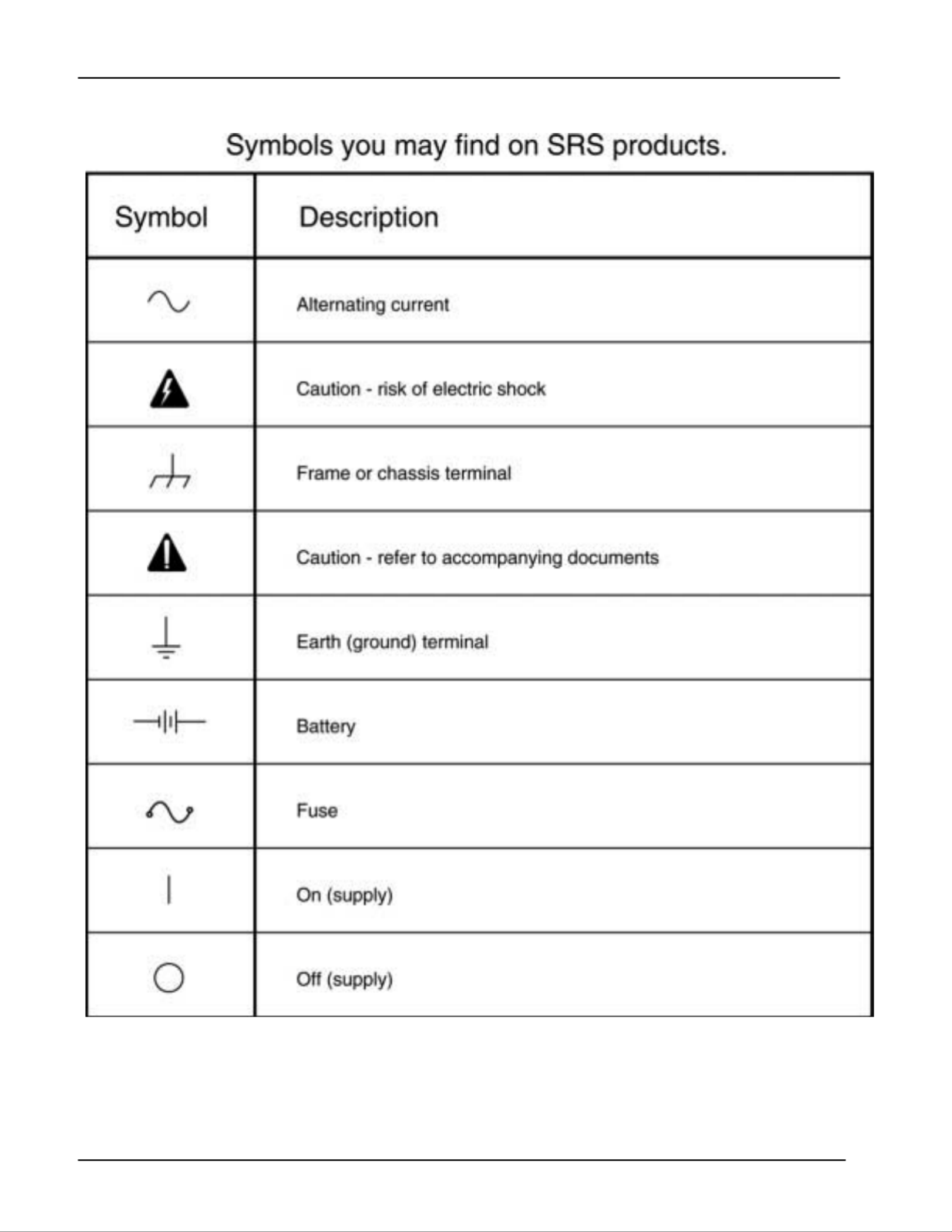
iv SRS Symbols
DS335 Synthesized Function Generator
Specifications v
DS335 Synthesized Function Generator
SPECIFICATIONS
FREQUENCY RANGE
Waveform Maximum Freq Resolution Accuracy
Sine 3.1 MHz 1 µHz ±25ppm
Square 3.1 MHz 1 µHz ±25ppm
Ramp 10 KHz 1 µHz ±25ppm
Triangle 10 KHz 1 µHz ±25ppm
Noise 3.5 MHz (Gaussian Weighting)
OUTPUT
Source Impedance: 50 Ω
Output may float up to ±40V (AC + DC) relative to earth ground.
AMPLITUDE
Range into 50Ω load (limited such that | Vac peak| + |Vdc | ≤ 5 V)
Vpp Vrms
Function Max. Min. Max. Min.
Sine 10V 50 mV 3.54V 0.02Vrms
Square 10V 50 mV 5.00V 0.03Vrms
Triangle 10V 50 mV 2.89V 0.01Vrms
Ramp 10V 50 mV 2.89V 0.01Vrms
Noise 10V 50 mV 1.62V 0.01Vrms
Range into a high impedance load (limited such that |V
ac peak| + |Vdc| ≤ 10 V)
Vpp Vrms
Function Max. Min. Max. Min.
Sine 20V 100 mV 7.07V 0.04Vrms
Square 20V 100 mV 10V 0.05Vrms
Triangle 20V 100 mV 5.77V 0.03Vrms
Ramp 20V 100 mV 5.77V 0.03Vrms
Noise 20V 100 mV 3.24V 0.02Vrms
Resolution 3 digits
Accuracy (with 0V DC Offset), 50Ω
ΩΩ
Ω terminated
Sine: Accuracy
± 0.1 dB
Square: Accuracy
± 2%
Triangle, Ramp: Accuracy
±2%

vi Specifications
DS335 Synthesized Function Generator
DC OFFSET
Range: ±5V into 50 Ω (limited such that | Vac peak| + |Vdc | ≤ 5 V)
±10V into hi-Z (limited such that | Vac peak| + |Vdc | ≤10 V)
Limitation: |Vdc | ≤ 2xVpp in all cases
Resolution: 3 digits
Accuracy: 1.2% of setting (DC only)
±0.8 mV to ±80 mV depending on AC and DC settings
WAVEFORMS
Sinewave Spectral Purity
Spurious (non-harmonic): -65 dBc to 1 MHz≤
≤ -55 dBc to 3.1 MHz
Phase Noise: ≤ -60dBc in a 30 KHz band centered on the carrier,
exclusive of discrete spurious signals
Subharmonic: ≤ -70 dBc
Harmonic Distortion: Harmonically related signals will be less than:
Level Frequency Range
≤ -60 dBc DC to 100 KHz
≤ -50 dBc .1 to 1 MHz
≤ -40 dBc 1 to 3.1 MHz
Square Wave
Rise/Fall Time: < 15 nS ±5 nS (10 to 90%), at full output
Asymmetry: < 1% of period + 3 nS
Overshoot: < 5% of peak to peak amplitude at full output
Ramps and Triangle
Rise/Fall Time 100 ±20 nS (3.5MHz Bessel Filter)
Linearity ±0.1% of full scale output
Settling Time < 200 ns to settle within 0.5% of final value at full output
FREQUENCY SWEEP
Type: Linear or Log, phase continuous
Waveform: Up, down, up-down, single sweep
Rate: 0.01 Hz to 1 kHz
Span: 1 µHz to 3.1 MHz (10 kHz for triangle or ramp)
FREQUENCY-SHIFT KEYING (FSK)
Type: Internal rate or External control, phase continuous
Waveform: Sine, Square, Triangle, Ramp
Rate: 0.01 Hz to 50 kHz (internal)
Shift Span: 1 µHz to 3.1 MHz (10 kHz for triangle or ramp)
External: TTL input, 1MHz maximum

Specifications vii
DS335 Synthesized Function Generator
SYNC & SWP/FSK OUTPUTS
SYNC: TTL level, active with all functions
SWP/FSK: TTL level, synchronous with internal Sweeps and FSK rates
TIMEBASE
Accuracy ±25 ppm (0 to 70° C)
Aging 5 ppm/year
Optional Timebase
Type: Temperature Compensated Crystal Oscillator
Stability: +/- 2.0 ppm, 0 to 50°C
Aging: 5 ppm first year, 2 ppm per year thereafter
GENERAL
Interfaces RS232-C (300 to 9600 Baud, DCE) and GPIB.
All instrument functions can be controlled over the interfaces.
Weight 8 lbs.
Dimensions 8.5" x 3.5" x 13" (W x H x L)
Power 25 Watts, 100/120/220/240 Vac 50/60 Hz

viii Specifications
DS335 Synthesized Function Generator

Abridged Command List ix
DS335 Synthesized Function Generator
Abridged Command List
Syntax
Variables i,j are integers. Variable x is a real number in integer, real, or exponential notation.
Commands which may be queried have a ? in parentheses (?) after the mnemonic. The ( ) are not sent.
Commands that may only be queried have a '?' after the mnemonic. Commands which be queriedmay not
have no '?'. Optional parameters are enclosed by {}.
Function Output Control Commands
AECL Sets the output amplitude/offset to ECL levels (1Vpp, -1.3V offset).
AMPL(?) x Sets the output amplitude to x. x is a value plus units indicator. The units can
be VP (Vpp), VR (Vrms). Example: AMPL 1.00VR sets 1.00 Vrms.
ATTL Sets the output amplitude/offset to TTL levels (5 Vpp, 2.5 V offset).
FREQ(?) x Sets the output frequency to x Hz.
FUNC(?) i Sets the output function. 0 = sine, 1 = square, 2 = triangle, 3 = ramp,
4 = noise.
INVT(?)i Sets the output inversion on (i=1) or off (i=0). Used with the ramp function.
KEYS(?) i Simulates a key press or reads the most recently pressed key.
OFFS(?)x Sets the output offset to x volts.
SYNC(?) i Turns the Sync output on (i=1) or off (i=0).
TERM(?) i Sets the output source impedance to 50Ω (i=0), Hi-Z (i=1).
Sweep control commands
FSEN(?) i Enables FSK on (i=1) or off (i=0). Valid only if SDIR2 is sent first.
*TRG Triggers single sweeps if in single trigger mode.
SDIR(?)i Sets the sweep direction 0 = Ramp, 1 = Triangle, 2 = FSK.
SPFR(?) x Sets the sweep stop frequency to x Hz.
SRAT(?) x Sets the sweep rate to x Hz.
STFR(?) x Sets the sweep start frequency to x Hz.
STYP(?) i Sets the sweep type. 0 = linear sweep, 1 = logarithmic sweep.
SWEN(?) i Turns sweeps on (i=1) or off (i=0).
TSRC(?) i Sets the trigger source for sweeps. 0 = single, 1 = internal sweep rate.
Setup Control Commands
*IDN? Returns the device identification.
*RCL i Recalls stored setting i.
*RST Clears instrument to default settings.
*SAV i Stores the current settings in storage location i.
Status Reporting Commands
*CLS Clears all status registers.
*ESE(?) j Sets/reads the standard status byte enable register.
*ESR? {j} Reads the standard status register, or just bit j of register.
*PSC(?) j Sets the power on status clear bit. This allows SRQ's on power up if desired.
*SRE(?) j Sets/reads the serial poll enable register.
*STB? {j} Reads the serial poll register, or just bit n of register.
STAT? {j} Reads the DDS status register, or just bit n of register.
DENA(?) j Sets/reads the DDS status enable register.

Getting Started 1-1
DS335 Synthesized Function Generator
Getting Started
Introduction This section is designed to familiarize you with the operation of the DS335
Synthesized Function Generator. The DS335 is a powerful, flexible
generator capable of producing both continuous and swept waveforms of
exceptional purity and resolution. The DS335 is also relatively simple to use,
and the following examples will lead you step-by-step through some typical
uses.
Data Entry Setting the DS335's operational parameters is done by pressing the key with
the desired parameter's name on it (FREQ, for example, to set the
frequency). The current value will be displayed. Some of the parameters are
labeled above the keys in light gray. To display those values first press the
SHIFT key and then the labeled key ([SHIFT][STOP FREQ], for example, to
display the type of waveform sweep set). Values are changed by the DATA
ENTRY keys. To directly enter a value simply type the new value using the
keypad and complete the entry by hitting one of the UNITS keys. If the value
has no particular units any of the UNITS keys may be used, otherwise select
the appropriate units key. If an error is made, pressing the corresponding
function key will backspace the cursor. If the key is pressed repeatedly the
display will eventually show the previous value. For example, if a new
frequency is being entered and the wrong numeric key is pressed, then
pressing the FREQ key will backspace the cursor. If the FREQ key is
pressed until the new entry is erased, then the last valid frequency value will
be displayed. The current parameter value may also be incremented or
decremented using the UP and DOWN ARROW keys. Pressing the UP
ARROW key will increment the flashing digit value by one, while pressing the
DOWN ARROW key will decrement the flashing digit value by one. If the
parameter value cannot be incremented or decremented, the DS335 will
beep and display an error message. Pressing [SHIFT][UP ARROW] or
[SHIFT][DOWN ARROW] changes the position of the blinking digit.
CW Function Generation Our first example demonstrates a CW waveform using the DS335's data
entry functions. Connect the front panel FUNCTION output to an
oscilloscope, terminating the output into 50 ohms. Turn the DS335 on and
wait until the message "TEST PASS" is displayed (if the self tests fail, refer to
TROUBLESHOOTING section of the manual).
1) Press [SHIFT][+/-]. This recalls the DS335's default settings.
2) Press [AMPL]. Then press [5][Vpp]. Displays the amplitude and sets it to 5 Vpp. The scope
should show a 5 Vpp 1 MHz sine wave.
3) Press [FUNC DOWN ARROW] twice. The function should change to a square wave and then a
triangle wave. The DS335 automatically performs a
frequency adjustment to match the maximum triangle
frequency (10kHz).
4) Press [FREQ] and then [1][kHz]. Displays the frequency and sets it to 1 kHz. The scope
should now display a 1 kHz triangle wave.
5) Press [UP ARROW]. The frequency will increment to 1.0001 kHz. The flashing
digit indicates a step size of 0.1 Hz.

1-2 Getting Started
DS335 Synthesized Function Generator
6) Press [SHIFT UP ARROW] twice. Observe that the blinking digit is shifted twice to the left
indicating a step size of 10 Hz.
7) Press [UP ARROW] three times. We've changed the output frequency to 10.0301 kHz.
Frequency Sweep The next example demonstrates a linear frequency sweep. The DS335 can
sweep the output frequency of any function over the entire range of allowable
output frequencies. There are no restrictions on minimum or maximum
sweep span. The sweep is phase continuous and may range from 0.01Hz to
1000 kHz.
Attach the FUNCTION output BNC to the oscilloscope, terminating the output
into 50 ohms. Set the scope to 2V/div. Attach the SWEEP rear-panel BNC
to the scope and set to 2V/div. The scope should be set to trigger on the
rising edge of this signal.
1) Press [SHIFT][+/-]. This recalls the DS335's default settings.
2) Press [AMPL] then [5][Vpp]. Sets the amplitude to 5Vpp.
3) Press [SHIFT] [STOP FREQ]. Verify linear sweep. "Lin" should be blinking now.
4) Press [SWEEP RATE] then [1][0][0] [Hz]. Set the sweep rate to 100 Hz. The sweep will take 10 ms
(1/100Hz). Set the scope time base to 1ms/div.
5) Press [START FREQ] then [1][0][0][kHz]. Set the sweep start frequency to 100 kHz.
6) Press [STOP FREQ] then [1][MHz]. Set the stop frequency to 1 MHz.
7) Press [SHIFT][START FREQ]. The SWP LED will light, indicating that the DS335 is
sweeping. The scope should show the SWEEP output as a
TTL pulse synchronous with the start of the sweep. The
FUNCTION output is the swept sine wave. The DS335 also
displays the option to switching to single shot sweeps at this
time. Pressing the up or down arrows at this time switches
the sweeps to single shot. Pressing [SHIFT][START FREQ]
triggers one sweep.
Introduction 2-1
DS335 Synthesized Function Generator
Introduction to Direct Digital Synthesis
Introduction Direct Digital Synthesis (DDS) is a method of generating very pure
waveforms with extraordinary frequency resolution, low frequency switching
time, crystal clock-like phase noise, and flexible sweeping capabilities. As an
introduction to DDS let's review how traditional function generators work.
Traditional Generators Frequency synthesized function generators typically use a phase-locked loop
(PLL) to lock an oscillator to a stable reference. Wave-shaping circuits are
used to produce the desired function. It is difficult to make a very high
resolution PLL so the frequency resolution is usually limited to about 1:10
6
(some sophisticated fractional-N PLLs do have much higher resolution). Due
to the action of the PLL loop filter, these synthesizers typically have poor
phase jitter and frequency switching response. In addition, a separate wave-
shaping circuit is needed for each type of waveform desired, and these often
produce large amounts of waveform distortion.
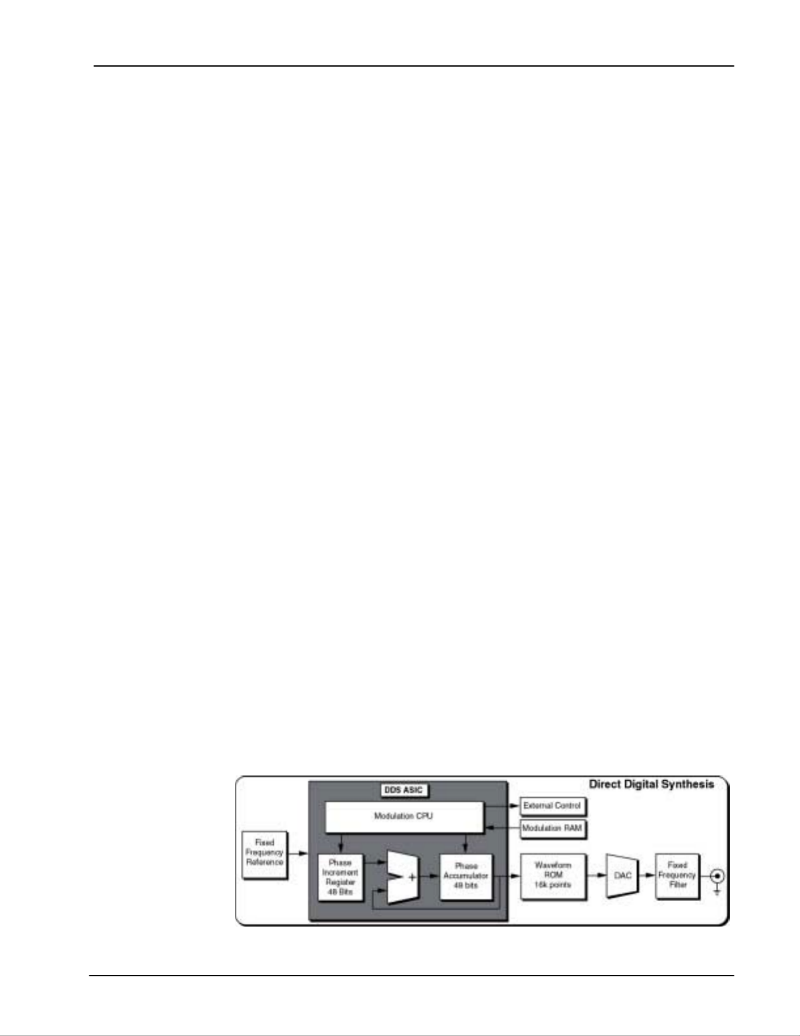
DDS DDS works by generating addresses to a waveform ROM to produce data for
a DAC. However, unlike earlier techniques, the clock is a fixed frequency
reference. Instead of using a counter to generate addresses, an adder is
used. On each clock cycle, the contents of a Phase Increment Register are
added to the contents of the Phase Accumulator. The Phase Accumulator
output is the address to the waveform ROM (see diagram below). By
changing the Phase Increment the number of clock cycles needed to step
through the entire waveform ROM changes, thus changing the output
frequency.
Frequency changes now can be accomplished phase continuously in only
one clock cycle. And the fixed clock eliminates phase jitter, requiring only a
simple fixed frequency anti-aliasing filter at the output.
The DS335 uses a custom Application Specific Integrated Circuit (ASIC) to
implement the address generation in a single component. The frequency
resolution is equal to the resolution with which the Phase Increment can be
set. In the DS335, the phase registers are 48 bits long, resulting in an
impressive 1:1014 frequency resolution. The ASIC also contains a modulation
control CPU that operates on the Phase Accumulator, Phase Increment, and
external circuitry to allow digital synthesis and control of waveform sweeps.
The Modulation CPU uses data stored in the Modulation RAM to produce
frequency sweeps. All modulation parameters, such as rate, and frequency
deviation, are digitally programmed.
Figure 1:
Block diagram of SRS
DDS ASIC
2-2 Introduction
DS335 Synthesized Function Generator
DDS gives the DS335 greater flexibility and power than conventional
synthesizers without the drawbacks inherent in PLL designs.
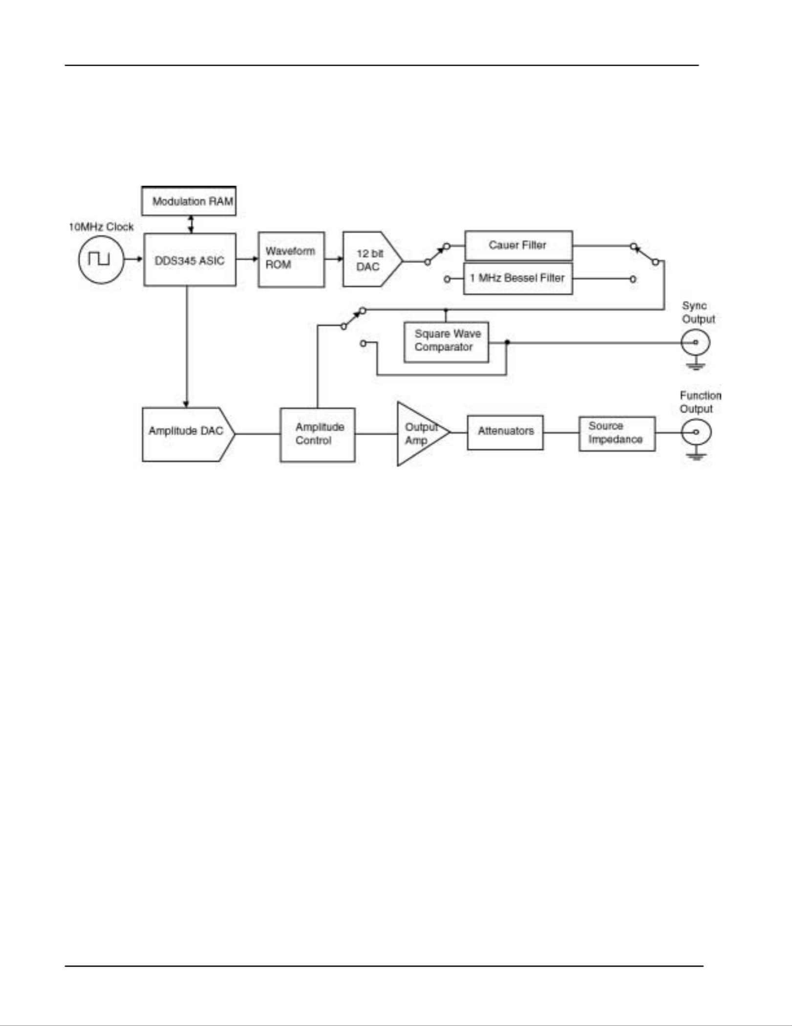
DS335 Description
Figure 2: DS335 Block Diagram
A block diagram of the DS335 is shown in Figure 2. The heart of the DS335
is a 10 MHz crystal clock. The 10 MHz clock controls the DDS ASIC,
waveform ROM, and high-speed 12bit DAC. Sampling theory limits the
frequency of the waveform output from the DAC to about 40% of 10 MHz, or
3 MHz. The 48 bit length of the ASIC's PIR's sets the frequency resolution to
about 36 nHz. These parameters and the DAC's 12 bit resolution define the
performance limits of the DS335.
The reconstruction filter is key to accurately reproducing a waveform in a
sampled data system. The DS335 contains two separate filters. For sine
wave generation the output of the DAC goes through a 7th order Cauer filter,
while ramps, and triangles pass instead through a 3.5 MHz 5
th order Bessel
filter. The Cauer filter has a cutoff frequency of 3.4 MHz and a stopband
attenuation of 86 dB, and includes a peaking circuit to correct for the
sin(x)/x amplitude response characteristic of a sampled system. This filter
eliminates any alias frequencies from the waveform output and allows
generation of extremely pure sine waves. However, the Cauer filter has very
poor time response and is only useful for CW waveforms. Therefore, the
Bessel filter was chosen for its ideal time response, eliminating rings and
overshoots from stepped waveform outputs.
The output from the filter passes through pre-amplifier attenuators with a 0 to
14 dB range. The attenuators are followed with a wide bandwidth power
amplifier that outputs a 10 V peak-to-peak into a 50 ohm load with a rise time
of less than 15 ns. The output of the power amplifier passes through a series
of four step attenuators (2, 4, 8, and 16 dB) that set the DS335's final output

Introduction 2-3
DS335 Synthesized Function Generator
amplitude. The post amplifier attenuators allow internal signal levels to
remain as large as possible, minimizing output noise and signal degradation.
Square waves and waveform sync signals are generated by discriminating
the function waveform with a high-speed comparator. The output of the
comparator passes to the SYNC OUTPUT and, in the case of square waves,
to the amplifier input. Generating square waves by discriminating the sine
wave signal produces a square wave output with rise and fall times much
faster than allowed by either of the signal filters.

2-4 Introduction
DS335 Synthesized Function Generator
Features 2-5
DS335 Synthesized Function Generator
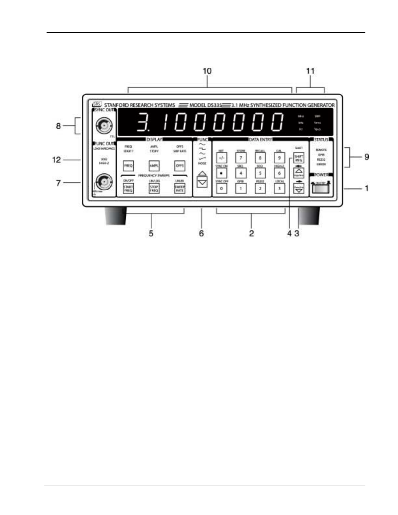
Front Panel Features
1) Power Switch The power switch turns the DS335 on and off. The DS335 has a battery
backed up system RAM that remembers all instrument settings.
2) Data Entry Keys The numeric keypad allows for direct entry of the DS335's parameters. To
change a parameter value simply type the new value. Entries are terminated
by the UNITS keys. A typing error may be corrected by pressing the
corresponding function key. For example, if the wrong numeric key is
pressed while entering a new frequency, pressing the [FREQ] key will
backspace over the last entered digit. If there are no digits left, the current
frequency value is displayed. The [+/-] key may be selected at any time
during numeric entry.
3) Units Keys The UNIT keys are used to terminate numeric entries. Simply press the key
with the desired units to enter the typed value. Some parameters have no
particular units and any of the unit keys may be used.
The unit keys also increase and decrease the numeric value in the DS335's
display. Pressing the [UPARROW] key adds one to the flashing digit value,
the [DOWN ARROW] key subtracts one from the flashing digit value. To
change the position of the flashing digit, press [SHIFT] [LEFT ARROW] or
[SHIFT] [RIGHT ARROW]. A few of the display menus have more than one
parameter displayed at a time. The [SHIFT][LEFT ARROW] and
[SHIFT][RIGHT ARROW] keys select between left and right.
4) Shift Key The shift key selects the function printed above the keys. Pressing [SHIFT]
and then the desired key to select the specific function (for example
[SHIFT][50Ω] sets the source impedance to 50Ω. When the SHIFT key is
pressed the SHIFT LED will light. Pressing [SHIFT] a second time will
deactivate shift mode.

2-6 Features
DS335 Synthesized Function Generator
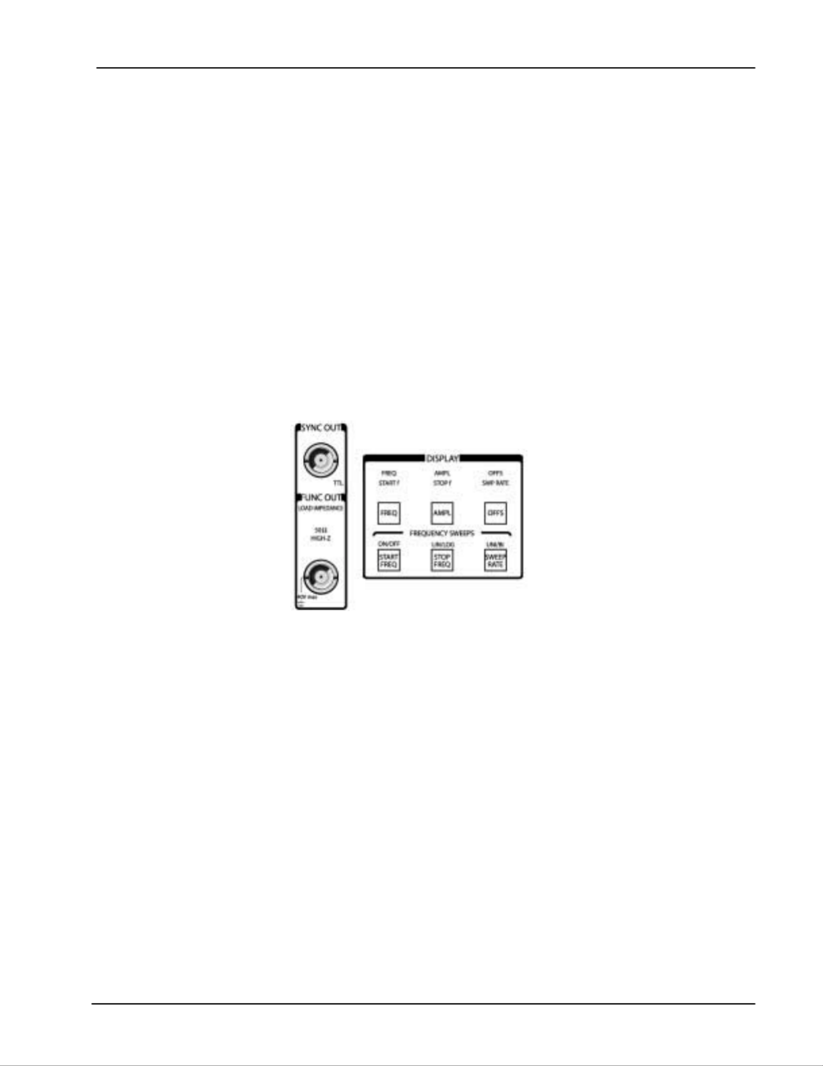
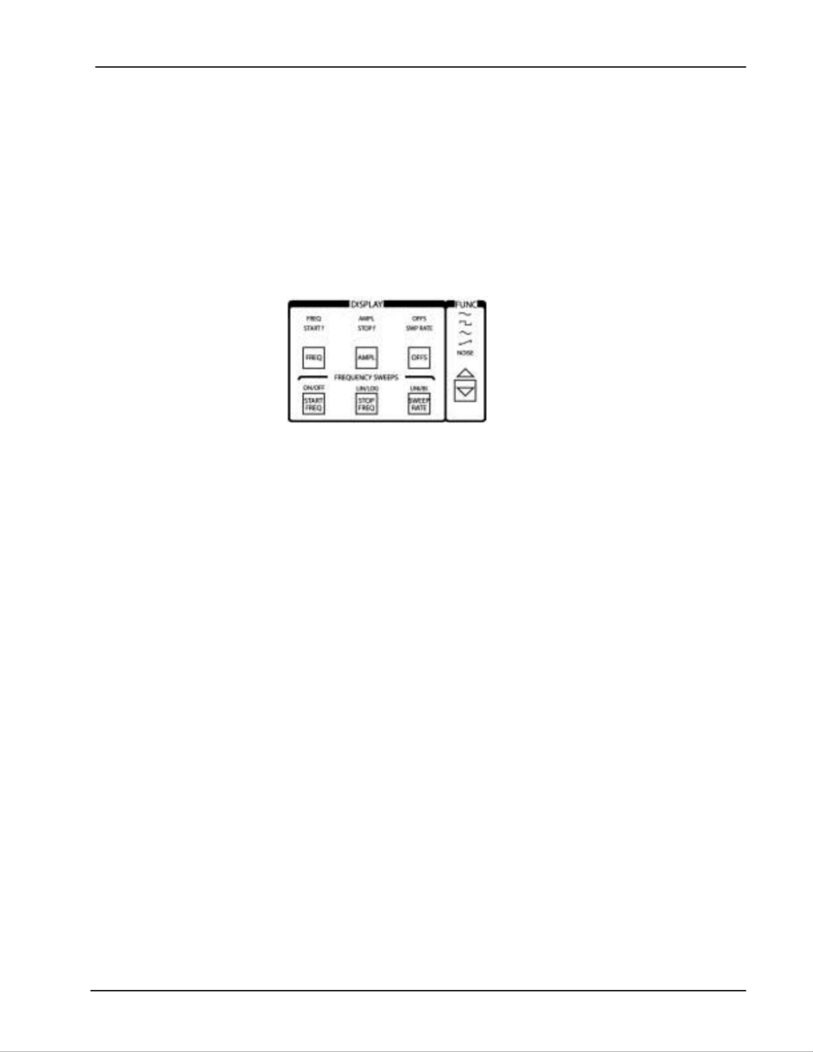
5) Sweep Key These keys control the different sweep parameters including: Start and Stop
Frequencies, Sweep Rate, Continuous or Single Sweep, Linear or Log
Sweep, Unidirectional or Bidirectional Sweeps, and FSK.
6) Function Keys These keys control the main function output. The Func [DOWN ARROW]
key and [SHIFT][UP ARROW] key select between the output functions. If the
output frequency is set beyond the range allowed for a waveform (> 10kHz
for triangle and ramp) an error message will be displayed and the frequency
will change to the maximum allowed for that function.
7) Main Function BNC This output has an impedance of 50Ω. The shield of this output may be
floated up to ±40V relative to earth ground.
8) Sync Output BNC This output is a TTL square wave synchronized to the main function output
and has a 50Ω output impedance. The shield of this output may be floated
up to ±40V relative to earth ground.
9) Status LEDs These four LEDs indicate the DS335's status. They are:
name function
REMOTE The DS335 is in GPIB remote state. The [3] key returns local
control.
GPIB Flashes on GPIB activity.
RS232 Flashes on RS232 activity.
ERROR Flashes on an error in the execution of a remote or local
command including range errors.
10) Parameter Display The 8 digit display shows the value of the currently displayed parameter. The
LEDs below in the DISPLAY section indicate which parameter is being
displayed. Error messages also appear on the display. When an error
message is displayed you can return to the normal display by pressing any
key.
11) Units LEDs The Units LEDs indicate the units of the displayed parameter. If no LED is lit
the value has no units. The SWP LED indicates that a sweep or FSK is in
progress.
12) Load Impedance LEDs These LEDs indicate the load impedance value as set by the user. The
amplitude and offset display values will change according to the load
impedance setting.
Features 2-7
DS335 Synthesized Function Generator
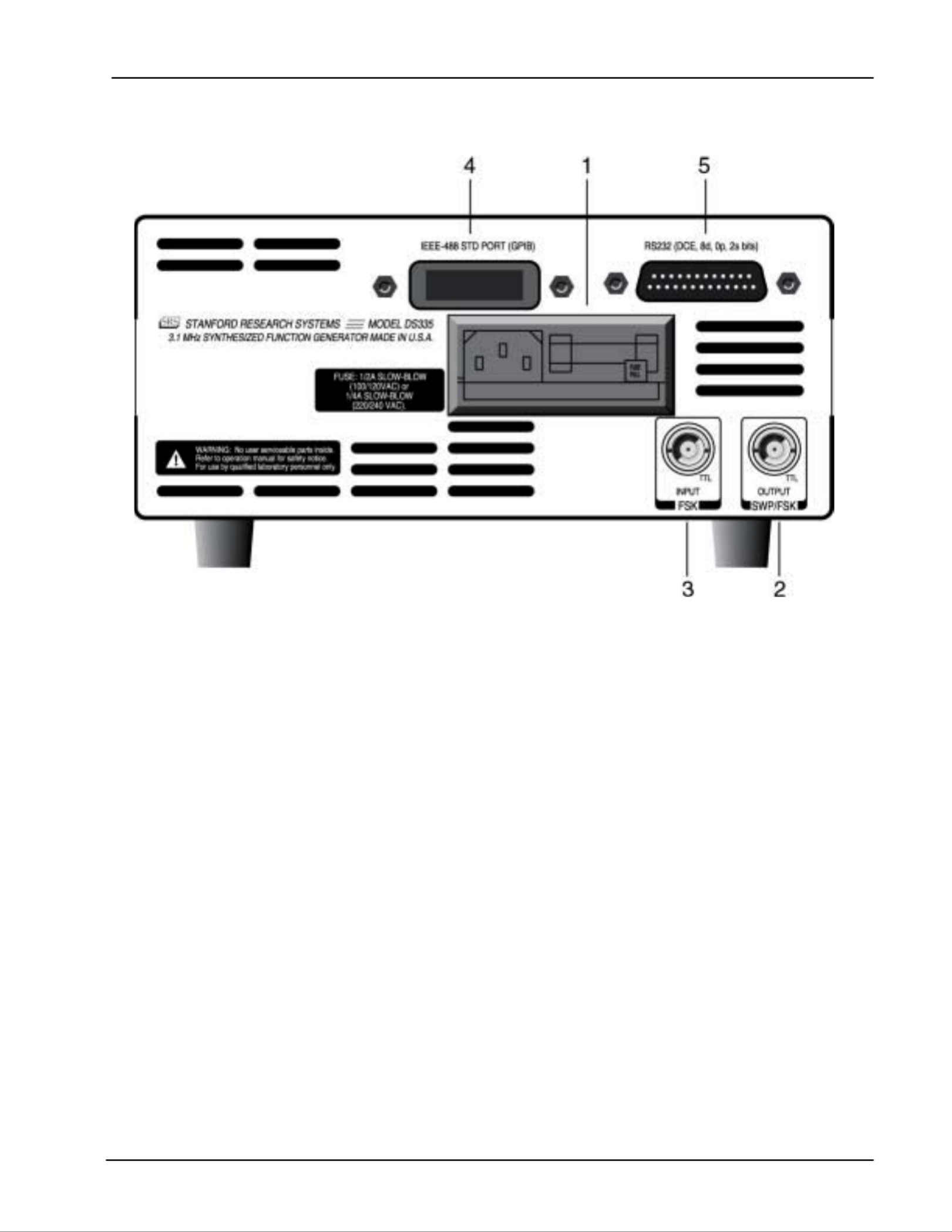
Rear Panel Features
1) Power Entry Module This contains the DS335's fuse and line voltage selector. Use a 1 amp slow
blow fuse for 100/120 volt operation, and a 1/2 amp fuse for 220/240 volt
operation. To set the line voltage selector for the correct line voltage, first
remove the fuse. Then, remove the line voltage selector card and rotate the
card so that the correct line voltage is displayed when the card is reinserted.
Replace the fuse.
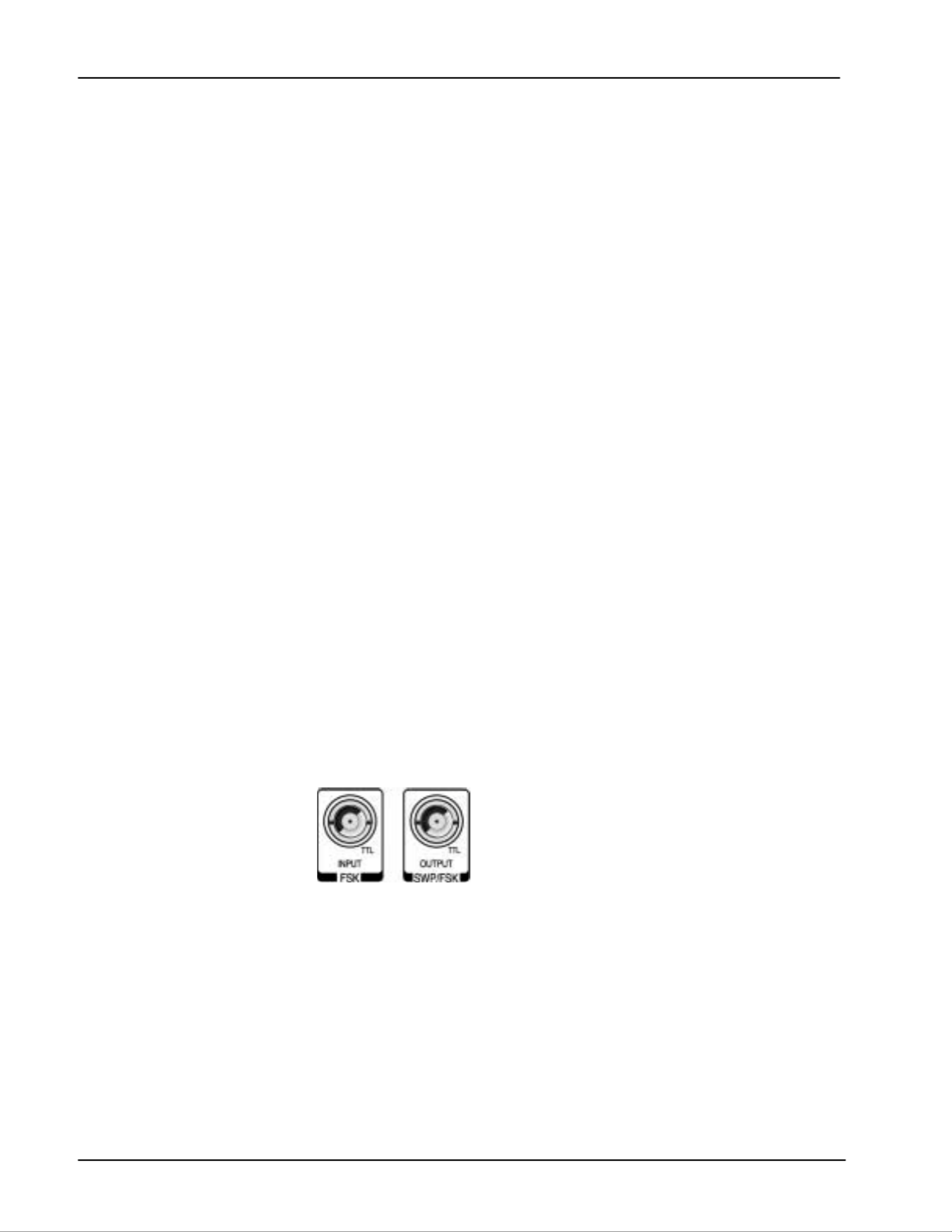
2) Sweep/FSK Output This output generates a TTL pulse that is synchronous with the DS335's
frequency sweep. When the DS335 is in FSK mode, the output voltage
reflects the present frequency at the FUNCTION output BNC (TTL LOW =
Start Frequency, TTL HIGH = Stop Frequency). The shield of this output is
tied to that of the function output and may be floated up to ±40V relative to
earth ground.
3) FSK Input The Frequency-Shift Keying input allows the user to toggle between the start
frequency and the stop frequency. The BNC takes a TTL level input. When
the input is low the start frequency is active, and when the input is high the
stop frequency is active. This input is sampled at 10 MHz.
4) GPIB Connector If the DS335 has the optional GPIB/RS232 interface this connector is used
for IEEE-488.1 and .2 compatible communications. The shield of this
connector is connected to earth ground.
5) RS232 Connector If the DS335 has the optional GPIB/RS232 interface this connector is used
for RS232 communication. The DS335 is a DCE and accepts 8 bits, no
parity, 2 stop bits at between 300 and 9600 Baud. The shield of this
connector is connected to earth ground.

2-8 Features
DS335 Synthesized Function Generator
Function Setting 2-9
DS335 Synthesized Function Generator
DS335 OPERATION
Introduction The following sections describe the operation of the DS335. The first section
describes the basics of setting the function, frequency, amplitude, and offset.
The second section explains sweeps and FSK. The third section explains
storing and recalling setups, running self-test and autocalibration, and setting
the computer interfaces.
Power-On When the power is first applied to the DS335 the unit will display its serial
number and ROM version for about three seconds. Then, the DS335 will
initiate a series of self-tests of the circuitry and stored data. The test should
take about three seconds and end with the message "TST PASS". If the self
test fails the DS335 will display an error message indicating the nature of the
problem (see the TROUBLESHOOTING section for more details). The
DS335 will still attempt to operate normally after a self-test failure, pressing
any key will erase the error message.
SETTING THE FUNCTION
OUTPUTS The FUNCTION and SYNC BNCs are the DS335's main outputs. Both of
these outputs are fully floating, and their shields may be floated relative to
earth ground by up to ±40V. Both outputs also have a 50 outputΩ
impedance. If the outputs are terminated into high impedance instead of 50W
the signal levels will be twice those programmed (the FUNCTION output may
also show an increase in waveform distortion). The output impedance should
be set properly from the front panel using the [SHIFT][5] or [SHIFT][6] keys.
Incorrect impedance matching may result in output voltages that do not
correspond to the displayed amplitudes and offsets. For example, if the
DS335 is set for a 50 Ohms source impedance and the output is connected
to a scope without a 50 Ohms terminator, then the scope waveform will be
twice the amplitude displayed on the DS335.The programmed waveform
comes from the FUNCTION output, while the SYNC output generates a TTL
compatible (2.5 V into 50 ) signal that is synchronous with the functionΩ
output. The SYNC signal is suppressed if the function is set to NOISE or
ARB. The SYNC signal can be disabled and enabled with the [SHIFT][0] and
[SHIFT][.] keys.
FUNCTION SELECTION The DS335's output function is selected using the FUNCTION UP/DOWN
arrow keys. Simply press the keys until the desired function LED is lit. If the
programmed frequency is outside of the range allowed for the selected
2-10 Function Setting
DS335 Synthesized Function Generator
function, an error message will be displayed and the frequency will be set to
the maximum allowed for that function.
Ramps Ramp functions usually ramp up in voltage, downward ramps may be set
entering a negative amplitude (see AMPLITUDE section).
FREQUENCY To display the DS335's output frequency press the [FREQ]. The frequency
units can be Hz, kHz, or MHz, and are indicated by the LEDs on the right of
the display. The DS335 has 1 µHz frequency resolution at all frequencies,
for all functions. The maximum frequency depends on the function selected
as shown below.
Function Frequency Range
Sine 1 µHz → 3.100000000000 MHz
Square 1 µHz → 3.100000000000 MHz
Triangle 1 µHz → 10,000.000000 Hz
Ramp 1 µHz → 10,000.000000 Hz
Noise 3.5 MHz White Noise (fixed)
Frequency is usually displayed by the DS335 with the highest resolution
possible. However, if the frequency is below 100 Hz, the DS335 will display
the frequency with 1 µHz resolution. At frequencies greater than 1 MHz the
digits below 0.1 Hz cannot be displayed, but the frequency still has 1 µHz
resolution and may be set via the computer interfaces.
If the function is set to NOISE the character of the noise is fixed with a band
limit of 3.5 MHz. The frequency is not adjustable and the FREQ display will
read "noise" instead of a numerical value.
Setting the Frequency To set the frequency of any function simply type a new value on the keypad
and complete the entry with the appropriate units (Hz, kHz, or MHz). Also,
the UP and DOWN arrow keys may be used to increment or decrement the
frequency by adding or subtracting one from the flashing digit.
AMPLITUDE Press [AMPL] to display the amplitude of the output function. The amplitude
may be set and displayed in units of Vpp and Vrms. The current units are
indicated by the LEDs at the right of the display. The amplitude range is
limited by the DC offset setting since |Vac peak| + |Vdc| ≤ 5 V (into 50Ω). If
the DC offset is zero the amplitude range for each of the functions is shown
below:
Note: The rms value for NOISE is based on the total power in the output
bandwidth (about 3.5 MHz) at a given peak to peak setting.
Vpp Vrms
Function Max. Min. Max. Min.
Sine 10V 50 mV 3.54V 0.02Vrms
Square 10V 50 mV 5.00V 0.03Vrms
Triangle 10V 50 mV 2.89V 0.01Vrms
Ramp 10V 50 mV 2.89V 0.01Vrms
Noise 10V 50 mV 1.62V 0.01Vrms
50Ω
ΩΩ
Ω Load Impedance
Function Setting 2-11
DS335 Synthesized Function Generator
Vpp Vrms
Function Max. Min. Max. Min.
Sine 20V 0.1V 7.07V 0.04Vrms
Square 20V 0.1V 10.0V 0.05Vrms
Triangle 20V 0.1V 5.77V 0.03Vrms
Ramp 20V 0.1V 5.77V 0.03Vrms
Noise 20V 0.1V 3.24V 0.02Vrms
HIGH-Z Load Impedance
Output Inversion The DS335's output may be inverted for ramp functions. This is useful for
turning positive ramps into negative ramps. Entering a negative amplitude
inverts the ramp output.
D.C. Only The output of the DS335 may be set to a DC level by entering an amplitude
of 0 V. When the amplitude is set to zero the A.C. waveform will be
completely shut off and the DS335 may be used as a DC voltage source.
DC OFFSET When the [OFFS] key is pressed the DC offset is displayed and the Vpp
indicator LED will be lit. A new value may be entered numerically with any
amplitude unit key. In general, the DC offset may range between ±5V, but is
restricted such that |Vac peak| + |Vdc| ≤ 5 V (into 50 Ohms), or | Vac peak | +
|Vdc| ≤ 10 V (into HIGH-Z). The DC offset is also restricted such that |Vdc| ≤
2 x Vpp. When the offset is changed, the output signal will briefly go to zero
as the output attenuators are switched, and then back to the set offset value.
SYNC ENABLE Pressing the [SHIFT] [.] key enables the SYNC OUT function. The
[SHIFT][0] disables the output by highly attenuating the output function
signal.

2-12 Function Setting
DS335 Synthesized Function Generator
Sweeps & FSK 2-13
DS335 Synthesized Function Generator
FREQUENCY SWEEPS & FSK
Introduction The DS335 can perform frequency sweeps of the sine, square, triangle, and
ramp waveforms. The sweeps may be up or down in frequency, and may be
linear or logarithmic in nature. The frequency changes during the sweep are
phase continuous and the sweep rate may be set between 0.01 Hz and
1000Hz. The DS335 has a SWEEP output that may be used to trigger an
oscilloscope. The DS335 is also capable of Frequency-Shift Keying (FSK).
FSK can be implemented either through the internal rate generator or the
back panel external input to toggle between two preset frequencies.
Sweep/FSK Enable Sweeps are enabled by pressing [SHIFT][START FREQ] in the Frequency
Sweeps menu. The DS335 displays the "CONT SNGL" menu which allows
the user to choose between continuous and single sweeps. The DS335 will
immediately start a continuos sweep unless the user presses the UP/DOWN
arrow key to select SINGLE sweep. Once a single sweep is selected, the
[SHIFT][START FREQ] key triggers the sweep. If the user has selected the
FSK function from the "UNI/BI" (Unidirectional/Bidirectional/FSK) menu, the
single/continuous sweep option is disabled and the "FS OFF" menu appears,
giving the user the choice to enable or disable the FSK function. Once the
FSK function is selected and enabled, the FSK output signal appears at the
Function Out BNC.
Sweep Type Pressing the [SHIFT] [STOP FREQ] key sets the sweep to either a linear or
log mode. The UP/DOWN arrow toggles between the two sweep types. The
output frequency of a linear sweep changes linearly during the sweep time.
The output frequency in a logarithmic sweep changes exponentially during
the sweep time, spending equal time in each decade of frequency. For
example, in a sweep from 1 kHz to 100 kHz, the sweep will spend half the
time in the 1 kHz to 10 kHz range and half the time in the 10 kHz to 100 kHz
range). It should be noted that these are digital sweeps, and that the sweep
is actually composed of 1500 to 3000 discrete frequency points, depending
on the sweep rate.
Sweep Waveform The type of sweep waveform may be set to UNIdirectional (ramp) or
BIdirectional (triangle) by pressing the [SHIFT][SWEEP RATE] key and then
pressing the UP/DOWN arrow keys. If FSK is selected, Frequency-Shift
keying is enabled and the sweeps are disabled. If the waveform is UNI
(Ramp) the DS335 sweeps from the start to the stop frequency, returns to
the start frequency and repeats continuously. For BI directional sweeps the
DS335 sweeps from the start to the stop frequency, then sweeps from the
stop frequency to the start frequency, and repeats. If the DS335 is set for a
single sweep, the sweep occurs only once.
2-14 Sweeps & FSK
DS335 Synthesized Function Generator
Sweep/FSK RATE The duration of the sweep is set by [RATE], and the value is entered or
modified with the keypad. The sweep rate may be set over the range of
0.01 Hz to1 kHz. The sweep rate is the inverse of the sweep time, a 0.01 Hz
rate is equal to a 100s sweep time, and a1 kHz rate is equal to a 1 ms sweep
time. For a TRIANGLE sweep the sweep time is the total time to sweep up
and down. If FSK is selected from the UNI/BI menu, then the "Sweep Rate"
button sets the FSK Rate. If the rate is set to 0 Hz then the rear panel FSK
BNC input toggles between the two preset frequencies. For any non zero
rate the DS335 will toggle between the two preset frequencies at the
specified rate. The maximum internal FSK rate is 50 kHz.
Sweep/FSK FREQUENCIES The DS335 may sweep over any portion of its frequency range: 1 µHz to
3.1 MHz for sine and square waves, 1 µHz to 100 kHz for triangle and ramp
waves. The sweep span is limited to six decades for logarithmic sweeps.
The DS335's sweep range is set by entering the start and stop frequencies.
In FSK mode, the DS335 will toggle between any two frequencies: 1µHz to
3.1 MHz for sine and square waves, and 1 µHz to 100 kHz for triangle and
ramp waves. There are no restrictions on the values of the start and stop
frequencies for linear sweeps.
Start and Stop Frequencies To enter the start and stop frequency press the [START FREQ] and [STOP
FREQ] keys. The span value is restricted to sweep frequencies greater than
zero and less than or equal to the maximum allowed frequency. If the stop
frequency is greater than the start frequency, the DS335 will sweep up. If the
start frequency is larger the DS335 will sweep down. If FSK is enabled the
DS335 toggles between the Start and Stop frequencies at the Sweep/FSK
Rate. If the rate has been set to zero then the rear panel FSK input is active.
A TTL low level activates the start frequency and a TTL high level activates
the stop frequency.
Sweep/FSK OUTPUT The rear-panel SWP/FSK output is synchronous with the sweep rate. This
output emits a TTL pulse at the beginning of every sweep cycle and can be
used to trigger an oscilloscope. When the start frequency is selected, the
Sweep output is at 0 Volts, and when the Stop frequency is selected the
Sweep level is at 5 Volts. The Sweep output is synchronous with the
frequency shifts.
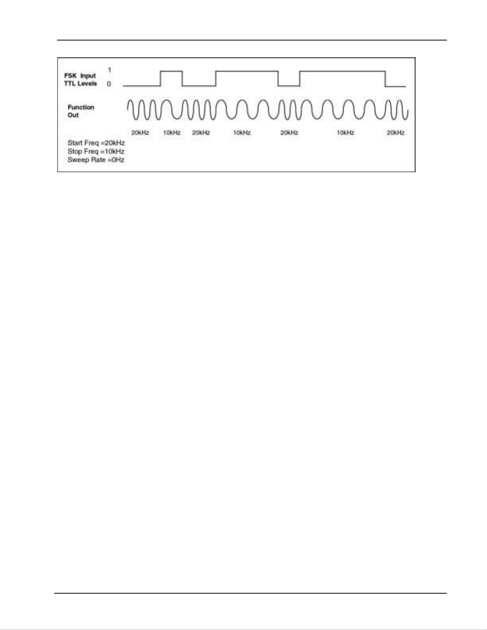
FSK Input The FSK input accepts TTL level signals. When enabled (FSK mode with
0 Hz rate), it is sampled at a 10 MHz frequency by the DS335. A low TTL
level selects the start frequency, and a high TTL level selects the stop
frequency (see example below). When the FSK Input is being used, the
Sweep output is disabled and stays at 0 Volts.
Sweeps & FSK 2-15
DS335 Synthesized Function Generator
External Frequency-Shift Keying (FSK) Example

DS335 Setup 2-17
DS335 Synthesized Function Generator
INSTRUMENT SETUP
Introduction This section describes the DS335's default settings, storing and recalling
settings, setting the computer interfaces, and running self-test.
Default Settings Press [SHIFT][+/-] to recall the DS335's default settings. The DS335's default
settings are listed below:
Storing Setups To store the DS335's current setup press [SHIFT][7] followed by a location
number in the range 0 - 9. After pressing any UNITS key to enter the
location number, the message "sto done" will be displayed, indicating that the
settings have been stored.
Recalling Stored Settings To recall a stored setting press [SHIFT][8] followed by a location number in
the range 0 - 9. After pressing any UNITS key to enter the location number
the message "rcl done" will be displayed, indicating that the settings have
been recalled. If nothing is stored in the selected location, or the settings are
corrupted, the message "rcl err" will be displayed.
GPIB Setup To set the DS335's GPIB interface press [SHIFT][1]. The GPIB enable
selection will be displayed. Use the [UP ARROW] and [DOWN ARROW]
keys to enable the GPIB interface. Press [SHIFT][1] again to display the
GPIB address. Enter the address desired using the numeric keypad or arrow
keys. The range of valid addresses is 0 - 30.
NOTE: If the DS335 does not have the optional GPIB/RS232 interfaces the
message "no GPIB" will be displayed when the GPIB menu is accessed.
Only one of the GPIB and RS232 interfaces may be active at a given time,
the RS232 interface is automatically disabled when GPIB is enabled.
Setting Default Value
Frequency 1 MHz
Function Sine
SYNC ON/OFF On
Load Impedance 50Ω
Display Frequency
Amplitude 1 Vpp
Offset 0.0 V
Inversion Off
Sweeps Off
Start Frequency 1Hz
Stop Frequency 3.1MHz
Trigger Source Continuous
Sweep/FSK Rate 100 Hz
Interface RS232
Baud Rate 9600
GPIB Address 22

2-18 Sweeps & FSK
DS335 Synthesized Function Generator
RS232 Setup To set the DS335's RS232 interface press [SHIFT][2]. The RS232 enable
selection will be displayed. Use the UP/DOWN ARROW keys to enable the
RS232 interface. Press [SHIFT][2] again to display the RS232 baud rate
selection. The available baud rates of 300, 600, 1200, 2400, 4800, or 9600
baud can be set with the UP/DOWN ARROW keys.
NOTE: If no interface option is present the message "no RS232" will be
displayed when the RS232 menu is accessed. Only one of the GPIB and
RS232 interfaces may be active at a given time, the GPIB interface is
automatically disabled when RS232 is enabled.
User Service Requests While the GPIB is enabled the user may issue a service request (SRQ) by
pressing [SHIFT][4]. The message "srq sent" will be displayed, and the GPIB
LED will light. The GPIB LED will go off after the host computer does a serial
poll of the DS335. Note: the user service request is in addition to the usual
service requests based on status conditions (see PROGRAMMING section
for details).
Communications Data Press [SHIFT][2] three times to display the last 256 characters of data that
have been received by the DS335. This display is a 3 character window into
the DS335's input data queue that could be scrolled to view the previous 256
characters. The data is displayed in ASCII hex format, with each input
character represented by 2 hexadecimal digits. The most recently received
character has a decimal point indicator. Pressing [DOWN ARROW] scrolls
the display to the beginning of the queue, and [UP ARROW] scrolls to later in
the queue.
AUTO-TEST
Introduction The DS335 has a built-in test routine that allows the user to test a large
portion of instrument functionality quickly and easily. Self-test starts every
time the DS335 is turned ON.
SELF-TEST The DS335's self-test is always executed on power-up. The test checks
most of the digital circuitry in the DS335, and should end with the display
"test pass". If the self-test encounters a problem it will immediately stop and
display a warning message. See the TROUBLESHOOTING section for a list
and explanation of the error messages. If the DS335 fails its test it still may
be operated.
The DS335 tests its CPU and data memory, ROM program memory,
calibration constant integrity, the computer interfaces, and the modulation
program memory
Items not tested are the connections from the PC boards to the BNC
connectors, the 12-bit waveform DAC, the output amplifier, the offset and
amplitude control circuits, and the output attenuators.
CALIBRATION BYTES It is possible to recall and modify the DS335 factory calibration bytes. Please
refer to the Test and Calibration Chapter for more detail.

3-2 Programming Commands
DS335 Synthesized Function Generator
There is no need to wait between commands. The DS335 has a 256
character input buffer and processes commands in the order received. If the
buffer fills up the DS335 will hold off handshaking on the GPIB and attempt
to hold off handshaking on RS232. If the buffer overflows the buffer will be
cleared and an error reported. Similarly, the DS335 has a 256 character
output buffer to store output until the host computer is ready to receive it. If
the output buffer fills up it is cleared and an error reported. The GPIB output
buffer may be cleared by using the Device Clear universal command.
The present value of a particular parameter may be determined by querying
the DS335 for its value. A query is formed by appending a question mark "?"
to the command mnemonic and omitting the desired parameter from the
command. If multiple queries are sent on one command line (separated by
semicolons, of course) the answers will be returned in a single response line
with the individual responses separated by semicolons. The default
response terminator that the DS335 sends with any answer to a query is
carriage return-linefeed <cr><lf> on RS232, and linefeed plus EOI on GPIB.
All commands return integer results except as noted in individual command
descriptions.
Examples of Command Formats
FREQ, 1000.0 <lf> Sets the frequency to 1000 Hz.
FREQ? <lf> Queries the frequency.
*IDN? <lf> Queries the device identification (query, no
parameters).
*TRG <lf> Triggers a sweep (no parameters).
FUNC 1 ;FUNC? <lf> Sets function to square wave(1) then queries the
function.
Programming Errors The DS335 reports two types of errors that may occur during command
execution: command errors and execution errors. Command errors are
errors in the command syntax. For example, unrecognized commands,
illegal queries, lack of terminators, and non-numeric arguments are examples
of command errors. Execution errors are errors that occur during the
execution of syntactically correct commands. For example, out of range
parameters and commands that are illegal for a particular mode of operation
are classified as execution errors.
No Command Bit The NO COMMAND bit is a bit in the serial poll register that indicates that
there are no commands waiting to be executed in the input queue. This bit is
reset when a complete command is received in the input queue and is set
when all of the commands in the queue have been executed. This bit is
useful in determining when all of the commands sent to the DS335 have
been executed. This is convenient because some commands, such as
setting the function or sweep, take a long time to execute and there is no
other way of determining when they are done. The NO COMMAND bit may
be read while commands are being executed by doing a GPIB serial poll.
There is no way to read this bit over RS232. Note that using the *STB?
query to read this bit will always return the value 0 because it will always
return an answer while a command is executing- the *STB? command itself!
DETAILED COMMAND LIST The four letter mnemonic in each command sequence specifies the
command. The rest of the sequence consists of parameters. Multiple
Produktspecifikationer
| Varumärke: | SRS |
| Kategori: | Generator |
| Modell: | DS335 |
Behöver du hjälp?
Om du behöver hjälp med SRS DS335 ställ en fråga nedan och andra användare kommer att svara dig
Generator SRS Manualer

26 Augusti 2024
26 Augusti 2024
Generator Manualer
- Generator Bosch
- Generator Braun
- Generator Philips
- Generator DeWalt
- Generator Honeywell
- Generator Anker
- Generator Vetus
- Generator Ferm
- Generator Eurom
- Generator Generac
- Generator Subaru
- Generator Gude
- Generator Makita
- Generator Draper
- Generator Hitachi
- Generator Black And Decker
- Generator Innoliving
- Generator Domo
- Generator Rowenta
- Generator Stanley
- Generator Hyundai
- Generator Westinghouse
- Generator Moulinex
- Generator Taurus
- Generator Parkside
- Generator Sun Joe
- Generator Metrix
- Generator ART
- Generator Einhell
- Generator Voltcraft
- Generator Dometic
- Generator Ferrex
- Generator Husqvarna
- Generator Craftsman
- Generator Zephyr
- Generator Powerplus
- Generator Trotec
- Generator Topcraft
- Generator Scheppach
- Generator Honda
- Generator Primo
- Generator Powerfix
- Generator CAT
- Generator Bavaria
- Generator Simpson
- Generator Gys
- Generator Zipper
- Generator Harvia
- Generator Fieldmann
- Generator Defort
- Generator Superior
- Generator Fuxtec
- Generator Truper
- Generator Cleanmaxx
- Generator Kinzo
- Generator Cocraft
- Generator Cecotec
- Generator Herkules
- Generator Toolcraft
- Generator Lumag
- Generator Telair
- Generator Endress
- Generator GW Instek
- Generator EcoFlow
- Generator Powerspot
- Generator Black Decker
- Generator Cummins
- Generator Briggs & Stratton
- Generator Kraftech
- Generator Bluetti
- Generator Anova
- Generator Global
- Generator King Craft
- Generator Zgonc
- Generator AudioControl
- Generator Duromax
- Generator CrossTools
- Generator Jackery
- Generator Blodgett
- Generator Lifan
- Generator Rigol
- Generator Robin America
- Generator Cleveland
- Generator Joy-it
- Generator Aim TTi
- Generator Swiss Kraft
- Generator Full Boar
- Generator Duro Pro
- Generator Alpha Tools
- Generator Powerkick
- Generator EizenKraft
- Generator Könner & Söhnen
- Generator Load Up
- Generator Sunbird Solar
- Generator Sunset
- Generator Solaaron
- Generator PowerTech
- Generator Woods
- Generator A-iPower
- Generator Stromkraft
- Generator ITC Power
- Generator MSW
- Generator Ribimex
- Generator Powerhouse
- Generator Arvey
- Generator Tektronix
- Generator PRAMAC
- Generator Prowork
- Generator DuroStar
- Generator ThermaSol
Nyaste Generator Manualer
27 Mars 2025
27 Mars 2025
27 Mars 2025
21 Februari 2025
21 Februari 2025
21 Februari 2025
13 Februari 2025
10 Februari 2025
9 Februari 2025
9 Februari 2025