Vauxhall Astra 2008 Bruksanvisning
Läs nedan 📖 manual på svenska för Vauxhall Astra 2008 (253 sidor) i kategorin Personbil. Denna guide var användbar för 9 personer och betygsatt med 4.5 stjärnor i genomsnitt av 2 användare
Sida 1/253

0 - 1VAUXHALL Astra
VAUXHALL Astra
Owner’s Manual
Model Year 2010
Edition: August 2009
TS 1612-A-10

Introduction .................................... 2
In brief ............................................ 6
Keys, doors and windows ............ 19
Seats, restraints ........................... 45
Storage ........................................ 63
Instruments and controls ............. 80
Lighting ...................................... 111
Infotainment system ................... 118
Climate control ........................... 121
Driving and operating ................. 129
Vehicle care ............................... 154
Service and maintenance .......... 198
Technical data ........................... 206
Customer information ................ 246
Index .......................................... 248
Contents

2Introduction
Introduction

Introduction 3
Vehicle specific data
Please enter your vehicle's data on
the previous page to keep it easily
accessible. This information is
available in the sections "Service and
maintenance" and "Technical data"
as well as on the identification plate.
Introduction
Your vehicle is a designed
combination of advanced technology,
safety, environmental friendliness
and economy.
This Owner's Manual provides you
with all the necessary information to
enable you to drive your vehicle
safely and efficiently.
Make sure your passengers are
aware of the possible risk of accident
and injury which may result from
improper use of the vehicle.
You must always comply with the
specific laws and regulations of the
country that you are in. These laws
may differ from the information in this
Owner's Manual.
When this Owner's Manual refers to
a workshop visit, we recommend your
Vauxhall Authorised Repairer.
All Vauxhall Authorised Repairers
provide first-class service at
reasonable prices. Experienced
mechanics trained by Vauxhall work
according to specific Vauxhall
instructions.
The customer literature pack should
always be kept ready to hand in the
vehicle.
Using this manual
■ This manual describes all options
and features available for this
model. Certain descriptions,
including those for display and
menu functions, may not apply to
your vehicle due to model variant,
country specifications, special
equipment or accessories.
■ The "In brief" section will give you
an initial overview.
■ The table of contents at the
beginning of this manual and within
each chapter shows where the
information is located.
■ The index will enable you to search
for specific information.
■ This Owner's Manual depicts left-
hand drive vehicles. Operation is
similar for right-hand drive vehicles.
■ The Owner's Manual uses the
factory engine designations. The
corresponding sales designations
can be found in the chapter
"Technical data".
■ Directional data, e.g. left or right, or
front or back, always relate to the
direction of travel.
■ The vehicle display screens may
not support your specific language.
■ Display messages and interior
labelling are written in bold letters.
Danger, Warnings and
Cautions
9Danger
Text marked 9 Danger provides
information on risk of fatal injury.
Disregarding this information may
endanger life.

4Introduction
9Warning
Text marked 9 Warning provides
information on risk of accident or
injury. Disregarding this
information may lead to injury.
Caution
Text marked Caution provides
information on possible damage to
the vehicle. Disregarding this
information may lead to vehicle
damage.
Symbols
Page references are indicated with
3. 3 means "see page".
Thank you for choosing a Vauxhall.
We wish you many hours of
pleasurable driving.
Your Vauxhall Team

Introduction 5

6In brief
In brief
Initial drive information
Vehicle unlocking
Radio remote control
Press button q to unlock and open
door.
To open the tailgate, press the button
under the moulding.
Radio remote control 3 19, Central
locking system 3 24, Load
compartment 3 27.
Electronic key
When in possession of the electronic
key, simply pulling the door handle
will unlock the vehicle and open the
door. To open the tailgate, press the
button under the moulding.
Open&Start system 3 21.

In brief 7
Seat adjustment
Seat positioning
Pull handle, slide seat, release
handle.
Seat adjustment 3 47, Seat position
3 47.
9Danger
Do not sit nearer than 25 cm (10
inches) from the steering wheel, to
permit safe airbag deployment.
Seat backrests
Turn handwheel. Do not lean on seat
when adjusting.
Seat adjustment 3 47, Seat position
3 47, Folding front passenger seat
backrest 3 49.
Seat height
Lever pumping motion
up = higher
down = lower
Seat adjustment 3 47, Seat position
3 47.

8In brief
Seat inclination
Pull lever, adjust inclination by
shifting body weight. Release lever
and audibly engage seat in position.
Seat adjustment 3 47, Seat position
3 47.
Head restraint adjustment
Press release button, adjust height,
engage.
Head restraints 3 45.
Seat belt
Pull out the seat belt and engage in
belt buckle. The seat belt must not be
twisted and must fit close against the
body. The backrest must not be tilted
back too far (maximum approx. 25 °).
To release belt, press red button on
belt buckle.
Seat belts 3 51, Airbag system
3 54, Seat position 3 47.

In brief 9
Mirror adjustment
Interior mirror
Swivel the lever on the underside to
reduce dazzle.
Interior mirror 3 32, Automatic anti-
dazzle interior mirror 3 33.
Exterior mirrors
Electric adjustment
Select the relevant exterior mirror and
adjust.
Electric adjustment 3 31, Convex
exterior mirrors 3 31, Folding
exterior mirrors 3 31, Heated
exterior mirrors 3 32.
Steering wheel adjustment
Unlock lever, adjust steering wheel,
then engage lever and ensure it is
fully locked. Do not adjust steering
wheel unless vehicle is stationary and
steering wheel lock has been
released.
Airbag system 3 54, Ignition
positions 3 130

10 In brief

In brief 11
Instrument panel overview
1Light switch ........................ 111
Instrument illumination ....... 115
Rear fog light ....................... 114
Front fog lights ................... 114
Headlight range
adjustment ......................... 112
2Side air vents ...................... 127
3Turn and lane-change
signals, headlight flash,
low beam and high beam ... 114
Exit lighting .......................... 116
Parking lights ...................... 114
Cruise control ....................... 96
4Steering wheel controls ......... 80
5Horn ...................................... 81
Driver airbag ......................... 54
6Instruments .......................... 86
7Windscreen wiper,
windscreen washer
system, headlight washer
system .................................. 81
8Left heated seat .................... 50
Deflation detection system .. 183
Tyre pressure monitoring
system ................................. 183
Ultrasonic parking sensors ... 92
Load compartment
unlocking ............................... 27
Hazard warning flashers ..... 113
Central locking system .......... 24
Sport mode ........................... 92
Right heated seat .................. 50
9Info-Display ........................... 96
Trip computer ...................... 106
Electronic climate control
system ................................. 124
10 Centre air vents ................... 127
11 Front passenger airbag ......... 54
12 Glovebox .............................. 63
13 Infotainment system ............ 118
14 Climate control system ........ 121
15 Ashtray .................................. 85
16 Start/Stop button .................. 21
17 Accelerator pedal ................ 129
18 Ignition switch with
steering wheel lock ............. 130
Sensor panel for
emergency operation of
Open&Start system ............... 21
19 Brake pedal ......................... 142
20 Clutch pedal ........................ 129
21 Steering wheel adjustment .... 80
22 Bonnet release lever ........... 155

12 In brief
Exterior lighting
Turn light switch
7= Off
8= Side lights
9= Headlights
AUTO = Automatic light control
Press light switch
>= Front fog lights
r= Rear fog light
Lighting 3 111.
Headlight flash, high beam and
low beam
Headlight flash = Pull lever
High beam = Push lever
Low beam = Push or pull lever
High beam 3 112, Headlight flash
3 112.
Turn and lane-change signals
To the right = Lever up
To the left = Lever down
Turn and lane-change signals
3 114.

In brief 13
Hazard warning flashers
Operated with the ¨ button.
Hazard warning flashers 3 113.
Horn
Press j.
Washer and wiper systems
Windscreen wiper
&=fast
%= slow
$= timed interval wipe or
automatic wiping with rain
sensor
§= off
For a single wipe when the
windscreen wiper is off, press the
lever down.
Windscreen wiper 3 81, Wiper
blade replacement 3 159.

14 In brief
Windscreen and headlight
washer systems
Pull lever.
Windscreen and headlight washer
system 3 81, Washer fluid 3 158.
Rear window wiper and washer
systems
Wipers on = push lever
Wipers off = push lever again
Wash = push lever and hold
Rear window wipers and washer
system 3 82, Wiper blade
replacement 3 159, Washer fluid
3 158.
Climate control
Heated rear window, heated
exterior mirrors
Heating is operated by pressing the
Ü button.
Heated rear window 3 35.

In brief 15
Demisting and defrosting the
windows
Air distribution to l.
Set temperature control to warmest
level.
Set fan speed to highest level or to
A.
Cooling n on.
Press button V.
Climate control system 3 121.
Transmission
Manual transmission
Reverse: with the vehicle stationary,
wait 3 seconds after depressing
clutch pedal and then pull up the
button on the selector lever and
engage the gear.
If the gear does not engage, set the
lever in neutral, release the clutch
pedal and depress again; then repeat
gear selection.
Manual transmission 3 137.
Manual transmission automated
N=neutral
o= drive
+= higher gear
-= lower gear
A= switch between Automatic and
Manual mode
R= reverse gear (with selector
lever lock)
Manual transmission automated
3 138.

16 In brief
Automatic transmission
P=park
R= reverse
N= neutral
D= drive
The selector lever can only be moved
out of P or N when the ignition is on
and the foot brake is depressed
(Selector lever lock). To engage P or
R, push button on selector lever.
The automatic transmission is
available in two versions 3 133.
Starting off
Check before starting off
■ Tyre pressure and condition
3 182, 3 231.
■ Engine oil level and fluid levels
3 156.
■ All windows, mirrors, exterior
lighting and number plates are free
from dirt, snow and ice and are
operational.
■ Proper position of seats, seat belts
and mirrors 3 47, 3 52, 3 31.
■ Brake function at low speed,
particularly if the brakes are wet.
Starting engine with ignition
switch
Turn key to position 1. Move the
steering wheel slightly to release the
steering wheel lock. Operate clutch
and brake, automatic transmission in
P or N, do not accelerate; for diesel
engines, turn the key to position 2 for
preheating and wait until control
indicator ! goes out; turn key to
3 and release key when engine is
running.

In brief 17
Starting engine with Start/Stop
button
The electronic key must be inside the
vehicle. Operate clutch and brake,
automatic transmission in P or N, do
not accelerate, for diesel engine,
press the button briefly to start
preheating, move the steering wheel
slightly to release the steering wheel
lock, wait until control indicator !
goes out and then press button for
1 second and release when the
engine is running.
Open&Start system 3 21.
Parking
■ Always apply the parking brake
without pressing the release button.
Apply as firmly as possible on
a downhill slope or uphill slope.
Depress the foot brake at the same
time to reduce operating force.
■ Switch off the engine. Turn the
ignition key to 0 and remove it or,
with the vehicle stationary, press
the Start/Stop button and open the
driver's door. Turn the steering
wheel until the steering wheel lock
is felt to engage.
For vehicles with automatic
transmission, the key can only be
removed when the selector lever is
in the P position. If P is not engaged
or the parking brake is not applied,
"P" flashes for a few seconds in the
transmission display.
■ If the vehicle is on a level surface or
uphill slope, engage first gear or set
the selector lever to P before
switching off the ignition. On an
uphill slope, turn the front wheels
away from the kerb.
If the vehicle is on a downhill slope,
engage reverse gear or set the
selector lever to P before switching
off the ignition. Turn the front
wheels towards the kerb.
■ Lock the vehicle and activate the
anti-theft alarm system with button
p on the radio remote control or
with the sensor in a front door
handle.
To activate the anti-theft locking
system, press button p twice or
touch the sensor in a front door
handle twice.
■ Do not park the vehicle on an easily
ignitable surface. The high
temperature of the exhaust system
could ignite the surface.
■ On vehicles with manual
transmission automated, control
indicator R flashes for a few
seconds after the ignition is
switched off if the parking brake has
not been applied 3 103.
■ Close windows and sunroof or
TwinTop.

18 In brief
■ The engine cooling fans may run
after the engine has been switched
off 3 155.
■ After running at high engine speeds
or with high engine loads, operate
the engine briefly at a low load or
run in neutral for approx. 30
seconds, before switching off in
order to protect the turbocharger.
Keys, locking 3 19, Laying the
vehicle up for a long period of time
3 154, TwinTop roof operation
3 38.

Keys, doors and windows 19
Keys, doors and
windows
Keys, locks ................................... 19
Doors ........................................... 27
Vehicle security ............................ 28
Exterior mirrors ............................ 31
Interior mirrors ............................. 32
Windows ...................................... 33
Roof ............................................. 36
Keys, locks
Keys
Replacement keys
The key number is specified in the
Car Pass or on a detachable tag.
The key number must be quoted
when ordering replacement keys as it
is a component of the immobiliser
system.
Locks 3 195, Open&Start system,
electronic key 3 21.
Key with foldaway key section
Press button to extend. To fold the
key, first press the button.
Car Pass
The Car Pass contains security
related vehicle data and should
therefore be kept in a safe place.
When the car is taken to a workshop,
this vehicle data is needed in order to
perform certain operations.
Radio remote control

20 Keys, doors and windows
Used to operate:
■ Central locking system
■ Anti-theft locking system
■ Anti-theft alarm system
■ Power windows
■ Electric roof on Astra TwinTop
The radio remote control has an
approximate range of up to 16 ft. This
range can be affected by outside
influences. The hazard warning
flashers confirm operation.
Handle with care, protect from
moisture and high temperatures and
avoid unnecessary operation.
Fault
If the central locking system cannot
be operated with the radio remote
control, it may be due to the following:
■ Range exceeded
■ Battery voltage too low
■ Frequent, repeated operation of the
radio remote control while not in
range, which will require re-
synchronisation
■ Overload of the central locking
system by operating at frequent
intervals, the power supply is
interrupted for a short time
■ Interference from higher-power
radio waves from other sources
Unlocking 3 24.
Radio remote control battery
replacement
Replace the battery as soon as the
range reduces.
Batteries do not belong in household
waste. They must be disposed of at
an appropriate recycling collection
point.
Key with foldaway key section
Extend the key and open the unit.
Replace the battery (battery type
CR 2032), paying attention to the
installation position. Close the unit
and synchronise.
Key with fixed key section
Have the battery replaced by
a workshop.

22 Keys, doors and windows
If the ignition has been switched off
and the vehicle is stationary, the
steering wheel lock activates
automatically when the driver's door
is opened or closed.
Control indicator 0 3 95.
Notice
Do not put the electronic key in the
load compartment or in front of the
Info-Display.
The sensor fields in the door handles
must be kept clean to ensure
unrestricted functionality.
If the battery is discharged, the
vehicle must not be towed, tow-
started or jump-started as the
steering wheel lock cannot be
disengaged.
Radio remote control
The electronic key likewise has
a radio remote control feature.
Emergency operation
If the radio remote control also fails,
the driver's door can be locked or
unlocked with the emergency key
contained in the electronic key: press
locking mechanism and remove the
cap by applying light pressure. Push
the emergency key outwards over the
detent and remove.

Keys, doors and windows 23
The emergency key can only lock or
unlock the driver's door. Unlocking
the entire vehicle 3 24. On vehicles
with anti-theft alarm system, the
alarm may be triggered when the
vehicle is unlocked. Deactivate the
alarm by switching on the ignition.
Hold the electronic key at the marked
position and press the Start/Stop
button.
To switch off the engine, press the
Start/Stop button for at least
1 second.
Lock the driver's door with the
emergency key. Locking the entire
vehicle 3 24.
This option is intended for
emergencies only. Seek the
assistance of a workshop.
Replacing battery in electronic
key
Replace the battery as soon as the
system no longer operates properly
or the range is reduced. The need for
battery replacement is indicated by
InSP3 in the service display or by
a check control message in the
Info-Display.
Service display 3 88, Info-Display
3 104.
Batteries do not belong in household
waste. They must be disposed of at
an appropriate recycling collection
point.

24 Keys, doors and windows
To replace the battery, press the
locking mechanism and remove the
cap by applying light pressure. Press
the cap on the other side outwards.
Replace the battery (battery type
CR 20 32), noting the installation
position. Engage caps.
Radio remote control
synchronisation
The radio remote control
synchronises itself automatically
during every starting procedure.
Fault
If the central locking cannot be
operated or the engine cannot be
started, the cause may be one of the
following:
■ fault in remote control 3 19
■ electronic key out of reception
range
To rectify the cause of the fault,
change the position of the electronic
key.
Central locking system
Unlocks and locks doors, load
compartment and fuel filler flap.
A pull on an interior door handle
unlocks the entire vehicle and opens
the door.
Notice
In the event of an accident of
a certain severity, the vehicle
unlocks automatically.
Notice
A short time after unlocking with the
remote control the doors are locked
automatically if no door has been
opened.
Unlocking
Radio remote control
Press button q.

Keys, doors and windows 25
Electronic key
Pull a door handle or press the button
under the tailgate moulding.
The electronic key must be outside
the vehicle, within a range of
approximately 3 ft.
Locking
Close doors, load compartment and
fuel filler flap. If the driver's door is not
closed properly, the central locking
system will not work.
Radio remote control
Press button p.
Electronic key
Touch the sensor field in the door
handle of one of the front doors.
The electronic key must be outside
the vehicle, within a range of
approximately 3 ft. The other
electronic key must not be inside the
vehicle.
2 seconds must pass before the
vehicle can be unlocked. Within this
time, it is possible to check that the
vehicle is locked.
Notice
The vehicle is not automatically
locked.
Central locking button

26 Keys, doors and windows
Press the m button: the doors are
locked or unlocked.
The LED in the button m illuminates
for approx. 2 minutes after locking
with the radio remote control.
If the doors are locked from the inside
whilst driving, the LED remains lit.
If the key is in the ignition switch,
locking is only possible if all doors are
closed.
Fault in remote control or
Open&Start system
Unlocking
Turn key or emergency key 3 21 in
the driver's door lock as far as it will
go. The entire vehicle is unlocked
when the driver's door is opened.
For Astra TwinTop with open roof -
after opening the driver's door, press
the central locking button m. The
vehicle will then be unlocked,
provided the anti-theft locking system
is not engaged. Switch on the ignition
to deactivate the anti-theft alarm
system. Open&Start system 3 21.
Locking
Close the driver's door, open the
passenger door, press central locking
button m. The vehicle is locked.
Close the passenger door.
Fault in central locking system
Unlocking
Turn key or emergency key 3 21 in
the driver's door lock as far as it will
go. The other doors can be opened by
using the interior handle (not possible
if the anti-theft locking system is
active). The load compartment and
fuel filler flap remain locked. To
deactivate the anti-theft locking
system, switch on the ignition 3 29.
Manual unlocking of boot lid
Folding the rear seat backrests
3 49.
From the interior, turn the rotary knob
on the inside of the boot lid
anticlockwise, this unlocks the boot
lid and opens it slightly.

Keys, doors and windows 27
Locking
Insert key or emergency key 3 21 into
opening above lock on inside of door
and operate lock by pressing until it
clicks. Then close the door. The
procedure must be carried out for
each door. The driver's door can also
be locked from the outside with the
key. The fuel filler flap and tailgate/
boot lid cannot be locked.
Child locks
9Warning
Use the child locks whenever
children are occupying the rear
seats.
Using a key or suitable screwdriver,
turn button on rear door lock to the
horizontal position: door cannot be
opened from inside.
Doors
Load compartment
Opening
Push the button under the tailgate
moulding.
9Warning
Do not drive with the tailgate open
or ajar, e.g. when transporting
bulky objects, since toxic exhaust
gases could enter the vehicle.

28 Keys, doors and windows
Notice
The installation of certain heavy
accessories onto the tailgate may
affect its ability to remain open.
Central locking system 3 24
Closing
Use the interior handle.
Do not press the button under the
moulding while closing as this will
unlock it again.
Close boot lid. The closed boot lid is
always locked. To lock the doors,
press button & on the remote
control.
Vehicle security
Anti-theft locking system
9Warning
Do not use the system if there are
people in the vehicle! The doors
cannot be unlocked from the
inside.
The system deadlocks all doors. All
doors must be closed or the system
cannot be activated.
If the ignition was on, the driver's door
must be opened and closed once so
that the vehicle can be secured.
Unlocking the vehicle disables the
mechanical anti-theft locking system.
This is not possible with the central
locking button.
Activating with the radio remote
control
Press p twice within 15 seconds.

Keys, doors and windows 29
Activating with the electronic key
Touch the sensor field in the front
door handle twice within 15 seconds.
The electronic key must be outside
the vehicle, within a range of
approximately 3 ft.
Anti-theft alarm system
The anti-theft alarm system is
operated in conjunction with the
central locking system.
It monitors:
■ Doors, load compartment, bonnet,
■ Passenger compartment,
■ Vehicle inclination, e.g. if it is
raised,
■ Ignition.
Unlocking the vehicle deactivates the
anti-theft alarm system.
Notice
Changes to the vehicle interior, such
as the use of seat covers, could
impair the function of passenger
compartment monitoring.
Activation without monitoring of
passenger compartment and
vehicle inclination
Switch off the monitoring of
passenger compartment and vehicle
inclination, when people or animals
are being left in the vehicle, because
of high volume ultrasonic signals,
movements triggering the alarm and
when the vehicle is on a ferry or train.
1. Close load compartment and
bonnet
2. Press button b. The LED in button
m flashes for maximum
10 seconds
3. Close doors
4. Activate the anti-theft alarm
system. The LED illuminates.
After approx. 10 seconds, the
system is armed. The LED flashes
until the system is deactivated
For Astra TwinTop, passenger
compartment monitoring is
deactivated if the roof is open to
prevent false alarms.

Keys, doors and windows 31
Exterior mirrors
Convex shape
The convex exterior mirror reduces
blind spots. The shape of the mirror
makes objects appear smaller, which
will affect the abilty to estimate
distances.
Manual adjustment
Adjust mirrors by swivelling lever in
required direction.
Electric adjustment
First select the relevant exterior mirror
then swivel the control to adjust.
Folding
For pedestrian safety, the exterior
mirrors will swing out of their normal
mounting position if they are struck
with sufficient force. Reposition the
mirror by applying slight pressure to
the mirror housing.
Manual folding
The exterior mirrors can be folded in
by pressing gently on the outer edge
of the housing.

32 Keys, doors and windows
Electric folding
Press the n button and both exterior
mirrors will fold.
Press button n again - both exterior
mirrors return to their original position.
If an electrically folded mirror is
manually extended, pressing the n
button will only electrically extend the
other mirror.
Heated
Operated by pressing the Ü button.
Heating functions with the engine
running and is switched off
automatically after a short time.
Interior mirrors
Manual anti-dazzle
To reduce dazzle, adjust the lever on
the underside of the mirror housing.

Keys, doors and windows 33
Automatic anti-dazzle
Dazzle from following vehicles at
night is automatically reduced.
Windows
Power windows
9Warning
Take care when operating the
power windows. Risk of injury,
particularly to children.
If there are children on the rear
seats, switch on the child safety
system for the power windows.
Keep a close watch on the
windows when closing them.
Ensure that nothing becomes
trapped in them as they move.
Power windows can be operated
■ with ignition on
■ within 5 minutes of switching
ignition off
■ within 5 minutes of switching
ignition key to position 1
After switching off the ignition, the
standby feature ceases when the
driver's door is opened.
Operate the control to open or close
the window.
For vehicles with automatic feature
pull or press the switch again to stop
window movement.
Astra TwinTop: when a door is
opened the window opens slightly
and closes automatically when the
door is closed.
Safety function
If the window glass encounters
resistance above the middle of the
window during automatic closing, it is
immediately stopped and opened
again.

34 Keys, doors and windows
In the event of closing difficulties due
to frost or the like, operate the switch
several times to close the window in
stages.
Central switch for electric
windows, Astra TwinTop
Press $ or " to open or close all
windows.
Child safety system for rear
windows
Switch z can be used to activate or
deactivate the switches in the rear
doors.
Operating windows from outside
The windows can be operated
remotely from outside the vehicle.
Radio remote control
Press q or p until all windows have
opened or closed.

Keys, doors and windows 35
Open&Start system
To close, touch the sensor field in the
door handle until all windows are
completely closed.
The electronic key must be outside
the vehicle, within a range of
approximately 3 ft.
Overload
If the windows are repeatedly
operated within short intervals, the
window operation is disabled for
some time.
Fault
If the windows cannot be opened or
closed automatically, activate the
window electronics as follows:
1. Close doors
2. Switch on ignition
3. Close the window completely and
operate the button for a further
5 seconds
4. Open the window completely and
operate the button for a further
1 second
5. Repeat for each window
Heated rear window
Operated by pressing the Ü button.
Heating functions with the engine
running and is switched off
automatically after a short time.
Astra TwinTop: The heated rear
window and heated exterior mirrors
are deactivated when the roof is
open.
Depending on the engine type, the
heated rear window comes on
automatically when the diesel particle
filter is being cleaned.
Sun visors
The sun visors can be folded down or
swivelled to the side to prevent
dazzling.
If the sun visors have integral mirrors,
the mirror covers should be closed
when driving.

36 Keys, doors and windows
Panoramic windscreen
To open roof lining: Turn handle to the
right and move roof lining rearward to
a suitable position.
To close roof lining: Move forward to
a suitable position. When moved all
the way forward, the roof lining
engages in position.
Notice
Close the sun visors before sliding
the roof lining.
Roof
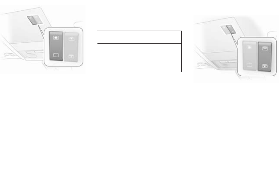
Sunroof
9Warning
Take care when operating the
sunroof. Risk of injury, particularly
to children.
Keep a close watch on the
movable parts when operating
them. Ensure that nothing
becomes trapped in them as they
move.
Sunroof can be operated with ignition
on.
Keys, doors and windows 37
Operated via a rocker switch in the
roof console.
Press the button briefly for activation
in steps. Hold down the button for
longer for automatic opening.
Raise
With the sunroof closed, press ü.
The sunroof is raised at the rear.
Open
Press ü again with the sunroof in the
raised position. The sunroof opens
automatically until it reaches its end
position.
When using a roof rack, check the
free movement of the sunroof in order
to avoid damage. It is only permitted
to raise the sunroof.
Caution
When using a roof rack, check the
free movement of the sunroof in
order to avoid damage. It is only
permitted to raise the sunroof.
Notice
If the top of the roof is wet, tilt
sunroof, allow water to run off and
then open sunroof.
Do not affix any stickers to sunroof.
Close
Hold down d until the sunroof is
completely closed.
For safety reasons, the roof closes
from its open position to approx.
20 cm. Hold d depressed to close
completely.
Sunblind
The sunblind is power operated.
The sunblind opens when the sunroof
opens.
Close or open the sunblind by
pressing button H or G.
Hold H depressed to close
completely.
Overload
If the system is overloaded, the power
supply is automatically cut off for
a short time.

38 Keys, doors and windows
Initialising the sunroof
If the sunroof and sunblind cannot be
operated (e.g. after disconnecting the
vehicle battery), activate the
electronics as follows:
1. Switch on ignition
2. Close sunroof and hold button
d depressed at least
10 seconds
3. Close sunblind and hold button
H depressed at least
10 seconds
Retractable hardtop
9Warning
Take care when operating the
convertible hardtop. Risk of injury.
Monitor the action zone above, to
the side and to the rear of the
vehicle during roof operation.
Make sure that nothing could
become pinched. Make sure no
one is in the action zone of the roof
or boot lid during roof operation.
Risk of injury.
Check the amount height, length
and width of available space
before operating the roof, e. g. in
a garage, parking garage or when
a bicycle rack is fitted.
Vehicle passengers should be
informed accordingly.
Before leaving the vehicle, remove
the ignition key in order to prevent
unauthorised operation of the
windows and sunroof.
Stand-by with ignition key in lock from
position 1, or for Open&Start-System
switch on ignition.
Requirements:
■ Vehicle is stationary or driving no
more than 18 mph
■ Load compartment blind is closed
and engaged 3 68
■ Boot lid is closed
If any of these requirements are not
fulfilled, a warning buzzer sounds
when the switch is actuated and the
roof does not open or close.
Open

Keys, doors and windows 39
There must be no objects in front of
the rear window or in the pivot area of
the roof and boot lid.
Hold button > in the roof console
depressed until the roof is completely
open and the boot lid is closed.
An acoustic signal sounds at the end
of the opening procedure.
The door windows are opened slightly
before the roof is opened. If button
> is pressed again after the
acoustic signal sounds, the door
windows will close.
Open with remote control
With vehicle stationary unlock the
vehicle. Press button q again and
keep pressed until the roof has
opened fully and the boot lid has
closed.
During operation with the remote
control, the door windows are opened
completely.
Close
Hold button < in the roof console
depressed until the roof and boot lid
are completely closed.
An acoustic signal sounds at the end
of the closing procedure.
The door windows are opened slightly
before the roof is closed. If button
< is pressed again after the
acoustic signal sounds, the door
windows will close.
Close with remote control
With vehicle stationary, lock the
vehicle. Press button p again and
keep pressed until the roof and boot
lid have closed completely.
Note
■ Do not open the load compartment
until the acoustic signal indicating
the end of the roof opening or
closing procedure has sounded.

40 Keys, doors and windows
■ The load compartment blind must
always be closed during roof
operation.
■ There must be no one and no
objects at the covers behind the
rear head restraints.
■ The roof can only be operated at
temperatures above -20 °C. If the
temperature is below this limit,
a gong will sound three times when
roof operation is requested.
■ Frequent operation of the roof with
the engine off discharges the
battery.
■ Repeated operation of the roof
without breaks can cause
overloading and therefore
malfunctions.
■ The roof can be held in an
intermediate position for 9 minutes
to facilitate cleaning of roof spaces.
This is done by disengaging the
actuation switch. One minute
before the end of this period,
a continuous buzzer sounds as
a warning that the hold period is
almost over and the roof could start
to move.
■ Activating the roof on uneven
ground can lead to malfunctions
and damage.
■ To prevent and remedy squeaking
noises of the roof seals a special
maintenance kit is available from
your Vauxhall Authorised Repairer.
It is recommended to apply this
product once a year for prevention.
Fault
The automatic drive of the roof is only
operational if the roof is in the proper
open or closed position.
Check if:
■ Load compartment blind is
engaged in closed position
■ Boot lid is completely closed
■ Outside temperature is above
-20 °C
■ There is sufficient battery voltage
■ There is a system overload
If the automatic drive is not
operational, two persons are required
to manually close the roof. See the
accompanying instructions for Astra
TwinTop. Professional assistance is
recommended.
Rollover protection system
The Astra TwinTop is equipped with
rollover protection with reinforced
windscreen frame and anti-roll bars
behind the rear seat head restraints.
Depending on the variant, the anti-roll
bars are either fixed or deploy
automatically in the event of an
impact of a certain severity.
Fixed anti-roll bars
Fixed anti-roll bars are secured to the
vehicle bodywork.

42 Keys, doors and windows
The roof can only be opened if the
load in the load compartment does
not exceed the height of the load
compartment blind or protrude
sideways. The load height must not
be exceeded. The load compartment
blind must be flat; objects below it
must not press it upwards. Otherwise
the roof and load may be damaged.
Blockage of boot lid
To avoid damage to the open roof,
boot lid or load, the boot lid can only
be closed if the electric load aid is in
the lower end position 3 72.
Failure of electric drive
Push locking lever forward.
Wind deflector
The rear seats cannot be occupied
when the wind deflector is in place.
Do not place any objects on the wind
deflector.
With tyre repair kit, the wind deflector
is folded down into a storage
compartment in the load
compartment below the loading floor
cover.
For the version with spare wheel, the
wind deflector is folded away in the
load compartment.
Fitting
Expand the collapsed wind deflector.

Keys, doors and windows 43
Join together the unfolded ends of the
wind deflector: Press in the pin at the
slider, guide the hinge over the pin
and release the slider so that the pin
engages in the hinge.
Insert the guide clips of the wind
deflector in the seat belt recesses
between the rear head restraints.
Pull the toggle of the right and left
locking pin and turn to lock.
Straighten out the wind deflector, turn
the toggle back and engage the
locking pin in the recess in the side
trim.
The wind deflector can be folded back
when not in use.
If the wind deflector is folded and the
rear seats are unoccupied, the wind
deflector can remain mounted in the
vehicle when the roof is closed.

44 Keys, doors and windows
Removing
Remove in reverse order, wind
deflector is completely folded down in
the load compartment:
■ for tyre repair kit in the
compartment below the loading
floor cover
■ for version with spare wheel , place
in load compartment
The wind deflector must never
protrude upwards or sideways above
the permissible loading height.

46 Seats, restraints
Rear centre head restraint
Pull the head restraint upwards or
press the catch to release and push
the head restraint downwards.
Adjusting the rear head restraints,
Astra TwinTop
Pull the head restraint up or press
both catches to release and then
push the head restraint down.
Do not place any objects on the cover
behind the head restraints or between
the head restraints and the anti-roll
bars.
Active head restraints
In the event of a rear-end impact, the
active head restraints tilt slightly
forwards. The head is more
effectively supported so the risk of
whiplash injury is reduced.
Active head restraints are identified
by the lettering ACTIVE on the head
restraint guide sleeves.
Notice
Approved accessories may only be
attached to the front passenger seat
head restraint if the seat is not in use.
Removing
Press the catches and pull up the
head restraint.

Seats, restraints 47
Front seats
Seat position
9Warning
Only drive with the seat correctly
adjusted.
■Sit with buttocks as far back against
the backrest as possible. Adjust the
distance between the seat and the
pedals so that legs are slightly
angled when pressing the pedals.
Slide the front passenger seat as
far back as possible.
■ Sit with shoulders as far back
against the backrest as possible.
Set the backrest rake so that it is
possible to easily reach the
steering wheel with arms slightly
bent. Maintain contact between
shoulders and the backrest when
turning the steering wheel. Do not
angle the backrest too far back. We
recommend a maximum angle of
approx. 25°.
■ Adjust the steering wheel 3 80.
■ Set seat height high enough to
have a clear field of vision on all
sides and of all display instruments.
There should be at least one hand
of clearance between the head and
the roof frame. Thighs should rest
lightly on the seat without pressing
into it.
■ Adjust the head restraint 3 45.
■ Adjust the height of the seat belt
3 52.
■ Adjust the thigh support so that
there is a space approx. two fingers
wide between the edge of the seat
and the hollow of the knee.
■ Adjust the lumbar support so that it
supports the natural shape of the
spine.
Seat adjustment
9Warning
Never adjust seats while driving as
they could move uncontrollably.
Seat positioning
Pull handle, slide seat, release
handle.

48 Seats, restraints
9Danger
Do not sit nearer than 25 cm (10
inches) from the steering wheel, to
permit safe airbag deployment.
Seat backrests
Turn handwheel. Do not lean on
backrest when adjusting.
Seat height
Lever pumping motion
up = higher
down = lower
Seat inclination
Pull lever, adjust inclination by
shifting body weight. Release lever
and audibly engage seat in position.

50 Seats, restraints
In vehicles with a panoramic window:
to tilt seats forward, push head
restraints down and lift up sun visors.
Armrest
Push raised armrest backward
against resistance and fold down.
The armrest can be moved to
different positions in stages by lifting
it.
Under the armrest there is a storage
compartment.
Heating
Adjust heating to the desired setting
by pressing the ß button for the
respective seat one or more times
with the ignition on. The control
indicator in the button indicates the
setting.
Prolonged use of the highest setting
for people with sensitive skin is not
recommended.
Seat heating is operational when the
engine is running.
Rear seats
Armrest
Armrest, Hatchback and Estate
Fold down the armrest, pulling the
strap obliquely down (45°).

Seats, restraints 51
Armrest, TwinTop
Pull the armrest by the strap, pivot it
down and position on the sit with the
flat side up.
The armrest is held in place on the
backrest with a retaining strap. To
fully remove the armrest, disengage
the bracket at the retaining strap.
Seat belts
The belts are locked during heavy
acceleration or deceleration of the
vehicle for the safety of the
occupants.
9Warning
Fasten seat belt before each trip.
In the event of an accident, people
not wearing seat belts endanger
their fellow occupants and
themselves.
Seat belts are only designed for use
by one person at a time. They are not
suitable for people younger than 12
years of age or smaller than 150 cm
(5 ft).
Periodically check all parts of the belt
system for damage and proper
functionality.
Have damaged components
replaced. After an accident, have the
belts and triggered belt tensioners
replaced by a workshop.
Notice
Make sure that the belts are not
damaged by shoes or sharp-edged
objects or are trapped. Prevent dirt
from getting into the belt retractors.
Seat belt control indicator X 3 90.
Belt force limiters
In the front seats, stress on the body
is reduced by gradual release of the
belt during a collision.

52 Seats, restraints
Belt tensioners
In the event of a head-on or rear-end
collision of a certain severity, the front
seat belt buckles are pulled down to
tighten the belts.
9Warning
Incorrect handling (e.g. removal or
fitting of belts) can trigger the belt
tensioners.
Deployment of the belt tensioners is
indicated by illumination of control
indicator v 3 90.
Triggered belt tensioners must be
replaced by a workshop. Belt
tensioners can only be triggered
once.
Notice
Do not affix or install accessories or
other objects that may interfere with
the operation of the belt tensioners.
Do not make any modifications to
belt tensioner components as this
will invalidate the vehicle type
approval.
Three-point seat belt
Fitting
Withdraw belt from retractor, guide it
untwisted across the body and insert
the latch plate in the buckle. Tension
the lap belt regularly whilst driving by
tugging the shoulder belt.
Loose or bulky clothing prevents the
belt from fitting snugly. Do not place
objects such as handbags or mobile
phones between the belt and your
body.

Seats, restraints 53
9Warning
The belt must not rest against hard
or fragile objects in the pockets of
your clothing.
Height adjustment
1. Pull belt out slightly.
2. Press button.
3. Adjust height and engage.
Adjust the height so that the belt lies
across the shoulder. It must not lie
across the throat or upper arm.
Do not adjust while driving.
Removing
To release belt, press red button on
belt buckle.
Seat belts on rear seats
Lead seat belts of the outer seats
through holders at the side if they are
not being used.
The seat belt for the middle seat can
only be withdrawn from the retractor if
the backrests are upright and are
engaged in their retainers.
Seat belts on rear seats, TwinTop
To prevent the seat belts from making
a flapping noise when the sunroof
and/or the windows are open, the
seat belts of unoccupied rear seats
can be secured behind the armrest.
Using the seat belt while pregnant
9Warning
The lap belt must be positioned as
low as possible across the pelvis
to prevent pressure on the
abdomen.

54 Seats, restraints
Airbag system
The airbag system consists of
a number of individual systems.
When triggered the airbag inflates
within milliseconds. They also deflate
so quickly that it is often unnoticeable
during the collision.
9Warning
If handled improperly the airbag
systems can be triggered in an
explosive manner.
Notice
The control electronics of the airbag
systems, belt tensioners and
deployable anti-roll bars are located
in the centre console area. Do not
put any magnetic objects in this
area.
Do not place any objects between
the airbag systems/anti-roll bar
covers and the occupants. Risk of
injury.
Do not stick anything on the airbag
covers and do not cover them with
other materials.
Each airbag/anti-roll bar is triggered
only once. Have deployed airbags/
anti-roll bars replaced by
a workshop.
Do not make any modifications to
the airbag system/anti-roll bars as
this will invalidate the vehicle type
approval.
In the event of airbag deployment
have the steering wheel, the
instrument panel, all panelling parts,
the door seals, the handles and the
seats removed by a workshop.
Control indicator v for airbag systems
3 90.
Front airbag system
The front airbag system consists of
one airbag in the steering wheel and
one in the instrument panel. These
can be identified by the word
AIRBAG.

Seats, restraints 55
There is also a warning label on the
side of the instrument panel, visible
when the front passenger door is
open.
The front airbag system is triggered in
the event of an accident of a certain
severity in the depicted area. The
ignition must be on.
Seat occupancy recognition 3 57.
Child restraint system with
transponders 3 62.
The forward movement of the front
seat occupants is decelerated,
thereby considerably reducing the
risk of injury to the upper body and
head.
9Warning
Optimum protection is only
provided when the seat is in the
proper position 3 47.
Keep the area in which the airbag
inflates clear of obstructions.
Fit the seat belt correctly and
engage securely. Only then the
airbag is able to protect.
Side airbag system

56 Seats, restraints
The side airbag system consists of an
airbag in each front seat backrest.
This can be identified by the word
AIRBAG.
The side airbag system is triggered in
the event of an accident of a certain
severity in the depicted area. The
ignition must be on.
Seat occupancy recognition 3 57.
Child restraint system with
transponders 3 62.
The risk of injury to the upper body
and pelvis in the event of a side-on
collision is considerably reduced.
9Warning
Keep the area in which the airbag
inflates clear of obstructions.
Notice
Only use protective seat covers that
have been approved for the vehicle.
Be careful not to cover the airbags.
Curtain airbag system
The curtain airbag system consists of
an airbag in the roof frame on each
side. This can be identified by the
word AIRBAG on the roof pillar.

Seats, restraints 57
The curtain airbag system is triggered
in the event of an accident of a certain
severity in the depicted area. The
ignition must be on.
The risk of injury to the head in the
event of a side impact is considerably
reduced.
9Warning
Keep the area in which the airbag
inflates clear of obstructions.
The hooks on the handles in the
roof frame are only suitable for
hanging up light articles of
clothing, without coat hangers. Do
not keep any items in these
clothes.
Seat occupancy recognition
Identified by a label on the lower
panel of the front passenger seat and
by control indicator y, which
illuminates for approx. 4 seconds
when the ignition is switched on.
The seat occupancy recognition
system deactivates the passenger
front and side airbag if the front
passenger seat is not occupied or is
fitted with a Vauxhall child restraint
system with transponders. The
curtain airbag system remains
activated.

58 Seats, restraints
9Danger
Only Vauxhall child restraint
systems with transponders should
be fitted on the front passenger
seats. Use of systems without
transponders poses a risk of fatal
injury.
Control indicator 3 90.
Notice
Anyone weighing less than 35 kg
should only travel on the rear seats.
Do not place any heavy objects on
the front passenger seat. Otherwise
the seat will register as occupied and
the airbag system for the front
passenger seat will not be
deactivated.
Do not use protective covers or seat
cushions on the front passenger
seat.
Notice
On the Astra TwinTop, there may be
interference in radio reception of
certain frequencies in the medium
waveband when the roof is open and
the front passenger seat is
unoccupied.
Child restraints
Child restraint systems
When a child restraint system is being
used, pay attention to the following
usage and installation instructions
and also those supplied with the child
restraint system.
Always comply with local or national
regulations. In some countries, the
use of child restraint systems is
forbidden on certain seats.
Selecting the right system
Children should travel facing
rearwards in the vehicle, until as old
as possible. It is appropriate to
change the system when the child's
head can no longer be properly
supported at eye height. The childs
cervical vertebrae are still very weak
and in an accident they suffer less
stress in the semi-prone rearward
position than when sitting upright.
Children under 12 years or under
150 cm (5 ft) tall should only travel in
an appropriate child restraint system.

Seats, restraints 59
When transporting children, use the
child restraint systems suitable for the
child's weight.
Ensure that the child restraint system
to be installed is compatible with the
vehicle type.
Ensure that the mounting location of
the child restraint system within the
vehicle is correct.
Only allow children to enter and exit
the vehicle at the side facing away
from the traffic.
When the child restraint system is not
in use, secure the seat with a seat belt
or remove it from the vehicle.
Notice
Do not stick anything on the child
restraint systems and do not cover
them with any other materials.
A child restraint system which has
been subjected to stress in an
accident must be replaced.

Seats, restraints 61
Permissible options for fitting an ISOFIX child restraint system
Weight class Size class Fixture On front passenger seat On rear outboard seats On rear centre seat
Group 0: up to 10 kg EISO/R1 X IL X
Group 0+: up to 13 kg EISO/R1 X IL X
D ISO/R2 X IL X
C ISO/R3 X IL X
Group I: 9 to 18 kg DISO/R2 X IL X
C ISO/R3 X IL X
B ISO/F2 X IL X
B1 ISO/F2X X IL X
A ISO/F3 X IL X
IL = Suitable for particular ISOFIX restraint systems of the 'specific-vehicle', 'restricted' or 'semi-universal' categories. The
ISOFIX restraint system must be approved for the specific vehicle type.
X = No ISOFIX child restraint system approved in this weight class.
ISOFIX size class and seat device
A – ISO/F3 = Forward-facing child restraint system for children of maximum size in the weight class 9 to 18 kg.
B – ISO/F2 = Forward-facing child restraint system for smaller children in the weight class 9 to 18 kg.
B1 – ISO/F2X = Forward-facing child restraint system for smaller children in the weight class 9 to 18 kg.
C – ISO/R3 = Rear-facing child restraint system for children of maximum size in the weight class up to 13 kg.
D – ISO/R2 = Rear-facing child restraint system for smaller children in the weight class up to 13 kg.
E – ISO/R1 = Rear-facing child restraint system for young children in the weight class up to 13 kg.

62 Seats, restraints
Isofix child restraint systems
Fasten vehicle-approved ISOFIX
child restraint systems to the
mounting brackets.
Child restraints with
transponders
A label on the child restraint system
indicates that it is fitted with
transponders.
Vauxhall child restraint systems with
transponders are automatically
detected if correctly installed to the
front passenger seat with seat
occupancy recognition.
Notice
There must be no objects (e.g.
plastic sheet or heating mats)
between the seat and the child
restraint system.
Seat occupancy recognition 3 57.

Storage 63
Storage
Storage compartments ................ 63
Load compartment ....................... 64
Roof rack system ......................... 77
Loading information ..................... 78
Storage compartments
Glovebox
The glovebox features a pen holder
and a place to store coins.
The glovebox shelf can be removed:
Disengage the shelf by pulling on the
front edge.
Refit the shelf by sliding it into the side
guide strips and engage it in the rear
panel by pushing.
The glovebox should be closed whilst
driving.
Lockable glovebox, Astra
TwinTop with Open&Start system
In addition to the electronic key of the
Open&Start system, there is
a standard key without remote control
for the glovebox lock.
Cupholders
Cupholders are located in the centre
console and in the door pockets of the
rear doors.
Additional cupholders are located in
the fold-down tables on the back of
the front seat backrests.

64 Storage
Sunglasses storage
Fold down and open.
Do not use for storing heavy objects.
Armrest storage
Storage in the front armrest
To open, press button and open
upper part of armrest.
Load compartment
Load compartment extension,
Hatchback 3-door / 5-door
Folding down rear backrests
Push head restraints all the way down
or remove 3 45.
Slide front seat forward slightly.
Disengage the backrest (single or
split) using the release button on one
or both sides and fold it down onto the
seat cushion.

Storage 65
Folding down centre backrests
Push head restraint down as far as
possible 3 45.
Disengage backrest using lever and
fold onto seat cushion.
Before restoring backrest to an
upright position, guide the seat belt
through the belt guides to protect
against damage.
Move rear seat backrests upright and
allow locking mechanisms to engage
audibly.
The three-point seat belt for the
centre rear seat can only be pulled
from the reel if the backrest is properly
engaged.
Load compartment extension,
Estate
Folding down rear backrests
Push head restraints all the way down
or remove 3 45.
Unhook hooks of load compartment
cover from head restraints 3 68.
Slide front seat forward slightly.
Disengage the backrest (single or
split) using the release button on one
or both sides and fold it down onto the
seat cushion.

66 Storage
Raise the seat cushion and fold the
backrest
Pull the strap on the seat cushion and
lift the rear of the cushion forwards
(split or one-piece).
Unhook hooks of load compartment
cover from head restraints 3 68.
Remove rear outer head restraints
and push centre head restraint all the
way down 3 45. Stow the removed
head restraints in the cavity below the
raised seat cushions.
Disengage backrest (one-piece or
split) using release button, fold
forward and engage.
Folding down centre backrests

Storage 67
Push head restraint down as far as
possible 3 45. Disengage backrest
using lever and fold onto seat
cushion. If the seat cushion is raised,
fold it forward until it engages.
Before restoring backrest to an
upright position, guide the seat belt
through the belt guides to protect
against damage. Press release
button and move rear seat backrests
upright, ensuring locking
mechanisms engage audibly.
With the seat cushions raised: insert
head restraints in backrests and
adjust 3 45. Fold back seat cushions,
making sure the belt buckles are
properly positioned.
Attach hooks of load compartment
cover to head restraints 3 68.
The three-point seat belt for the
centre rear seat can only be pulled
from the reel if the backrest is properly
engaged.
Load compartment extension,
TwinTop
Loading area between rear seats
Pull out the armrest by the strap.
The armrest is held in place on the
backrest with a retaining strap. To
fully remove the armrest, disengage
the bracket at the retaining strap.
Pull the handle and fold down the
cover.

68 Storage
The cover behind the armrest can be
locked from load compartment:
horizontal position = locked
vertical position = unlocked
Stowage in the load
compartment, Estate
There is a stowage compartment at
the right side of the load
compartment.
The fuse box is on the left side behind
the cover in the load compartment
side panelling 3 177
Cargo box 3 70.
The tyre repair kit is on the right side
behind the cover 3 185.
Load compartment cover
Hatchback 3-door / 5-door
Removing
Unhook retaining straps from tailgate.
Pull cover from the side guides.
Fitting
Engage cover in side guides and fold
downwards. Attach retaining straps to
tailgate.
Estate
Do not place any heavy or sharp-
edged objects on the load
compartment cover.
Opening
Press handle on load compartment
cover rearwards; the cover
automatically engages in its end
position.
Closing
Remove load compartment cover
from side brackets. It rolls up
automatically.

Storage 69
Pull the cover towards the rear using
the handle and engage it in the
retainers at the sides.
To cover the gap between the load
compartment cover and the rear
backrests, there is a cover on the
cartridge. Attach the two hooks of the
cover to the head restraint guide rods.
If the safety net is mounted, run the
hooks through the net mesh.
Removing
Open the load compartment cover
and detach the hooks from the head
restraints.
Pull the release lever. Lift right side of
cover first, then pull left side out of
recess.
Fitting
Insert the left side of the load
compartment cover in the recess, pull
the release lever, insert the right side
of the load compartment cover and
engage.
Attach the hooks on the head
restraints.
TwinTop
Opening
Release load compartment blind from
recesses on left and right, blind rolls
up automatically.
Closing
Pull the cover towards the rear using
the handle and engage it in the
retainers at the sides.
Do not place any objects on the load
compartment cover.
There must be no objects outside of
or on top of the cover when the roof is
open or in the process of opening.

70 Storage
The roof can only be operated with
the blind engaged in the recess.
Load rails and hooks
In Estate, install the hooks in the
desired position in the rails: insert the
hook in the upper groove on the rail
and press in the lower groove.
Lashing eyes
The lashing eyes are designed to
secure items against slippage, e.g.
using lashing straps, luggage net or
safety net.
Cargo management system
The FlexOrganizer is a flexible
system for dividing the load
compartment or securing loads in an
Estate.
The system consists of:
■ adapters
■ variable partition net
■ mesh pockets
■ hooks
The components are fitted in two rails
in the side panels using adapters and
hooks. The partitioning net can also
be fitted directly in front of the tailgate.

Storage 71
Variable partition net
Insert an adapter into each rail: fold
open the handle plate, insert adapter
into upper and lower groove of rail
and move to required position. Turn
handle plate upwards to lock the
adapter. The rods of the net must be
extended before inserting into the
adapters: pull out all of the end pieces
and lock by rotating clockwise.
To install, push rods together a little
and insert into the relevant openings
in the adapters. The longer rod must
be inserted into the upper adapter.
To remove, press the net rod together
and remove from the adapters. Fold
open the adapter handle plate,
disengage from lower groove and
then from upper groove.
Hooks and net pocket
Net pocket can be suspended from
the luggage hooks.
Cargo box
Foldable box under the floor cover
used to divide the load compartment.
The cargo box may only be loaded
when the backrests are engaged in
an upright position.
To remove the cargo box floor cover,
remove first the right half then the left
half. For models with towing
equipment, first release the coupling
ball bar fixing strap and thread this
through the eye.
Install in reverse order.

72 Storage
Loading assist
On TwinTop: The loading aid Easy
Load makes it possible to comfortably
load the load compartment when the
roof is open. Pressing the loading aid
button will raise the roof folded up in
the load compartment 25 cm. This
enlarges the load opening of the load
compartment.
■ Open the boot lid
■ Unhook load compartment blind
and attach to rear window frame
with holder
■ Briefly press loading aid button:
The folded roof is raised. The roof
remains in this end position for
approx. 9 minutes
■ Observe marked maximum load
height
■ Suspend the load compartment
blind from the rear window frame
and engage in the recesses. The
load compartment blind must be
flat; objects underneath it must not
push it upwards.
■ Briefly press loading aid button:
The folded roof is lowered.
■ Close the boot lid only after the
confirmation signal has sounded.
Otherwise the roof could be
damaged.
9Warning
Take care when operating the
loading aid. Risk of injury.
Make sure that nothing can
become trapped.
Make sure no one is in the action
zone during operation. Risk of
injury.
This is especially important for
children. Inform passengers
accordingly.

Storage 73
Note
■Do not place objects on or near the
load compartment blind
■ The folded roof can only be lowered
when the blind is closed.
Otherwise, a warning buzzer will
sound three times
■ The movement of the tilted roof can
be stopped by pressing the loading
aid button and another longer press
reverses the direction of the
movement
■ A confirmation buzzer is heard in
the upper and lower roof end
positions when the roof is tilted
■ Only close the tailgate once the
confirmation signal has sounded to
indicate that the loading aid is in its
lower end position
■ If the loading aid is not in its lower
end position when the boot lid is
closed, a warning tone sounds or
the tailgate is blocked mechanically
3 38
■ Do not touch moving parts
■ One minute before the end of the
hold time for the raised loading aid,
a warning buzzer will sound to
remind you to lower the roof
■ The loading aid is only operable
when the vehicle is unlocked
■ Frequent operation of the loading
aid with the engine off discharges
the battery
■ Repeated operation of the loading
aid can cause malfunctions
Safety net
The safety net is available on the
Estate and can be installed behind
the rear seats or, if the rear seat
backrests are folded and the seat
cushions raised, behind the front
seats.
Passengers must not be transported
behind the safety net.
Installation
There are two installation openings in
the roof frame: suspend and engage
rod of net at one side, compress rod
and suspend and engage at other
side.

Storage 75
Load compartment grille
To transport long objects, part of the
load compartment grille behind the
passenger seat can be opened:
Release passenger seat back and
fold forward.
Press bracket down and fold grille
section up.
Lock grille in open position.
To close the grille section from the
open position, push bracket down,
fold down grille and engage.
Check that the closed grille is properly
locked.
Folding tray
Located in the front seat backrests.
Open by pulling upward until it
engages.
Fold away by pressing down past the
resistance point.
Do not place any heavy objects on the
folding tray.
Warning triangle
Hatchback 3-door / 5-door,
TwinTop
Store warning triangle in rear load
compartment wall: first fit warning
triangle into recess on left and then
insert in guide on right.
To remove the warning triangle, lift to
the right and pull out to the right.

76 Storage
For vehicles with cargo box: Lift the
warning triangle with the right half of
the cargo box. Pull out the warning
triangle to the right.
Estate, Van
Stow the warning triangle in the space
in the tailgate and fasten with the right
and left straps.
First aid kit
Hatchback 3-door / 5-door
Secure the first-aid kit to the right load
compartment wall using the retaining
strap.
Estate
Fasten the first-aid kit to the left load
compartment wall with a retaining
strap.

Storage 77
Van
Place first aid kit in stowage
compartmen behind the driver's seat.
To open the cover, press the locking
tab.
TwinTop
Store the first-aid kit in the recess
behind the strap in the left load
compartment wall.
Roof rack system
Roof rack
For safety reasons and to avoid
damage to the roof, the vehicle
approved roof rack system is
recommended.
Roof loads are not permitted on the
Astra TwinTop.
Follow the installation instructions
and remove the roof rack when not in
use.
Version without roof railing

80 Instruments and controls
Instruments and
controls
Controls ....................................... 80
Warning lights, gauges and
indicators ..................................... 86
Information displays ..................... 96
Vehicle messages ...................... 103
Trip computer ............................. 106
Controls
Steering wheel adjustment
Unlock lever, adjust steering wheel,
then engage lever and ensure it is
fully locked.
Do not adjust steering wheel unless
vehicle is stationary and steering
wheel lock has been released.
Steering wheel controls
The Infotainment system and the
Info-Display can be operated via the
controls on the steering wheel.
Further information is available in the
Infotainment system manual.

Instruments and controls 81
Horn
Press j.
Windscreen wiper/washer
Windscreen wiper
The lever always springs back to its
original position.
&= fast
%= slow
$= adjustable timed interval wipe
§= Off
For a single wipe when the
windscreen wiper is off, press the
lever down.
Run through the windscreen wiper
stages by pushing the lever past the
resistance point and holding. An
acoustic signal sounds at §.
Do not use if the windscreen is frozen.
Switch off in car washes.
Adjustable wiper interval
To set the wiper interval to a value
between 2 and 15 seconds: Switch on
ignition, move lever down from
position §, wait until wiping frequency
reaches desired time interval and
raise lever to $.

82 Instruments and controls
After turning on the ignition and
setting the lever to $, the interval is
set to 6 seconds.
Automatic wiping with rain sensor
$=Automatic wiping with rain
sensor
The rain sensor detects the amount of
water on the windscreen and
automatically regulates the frequency
of the windscreen wipers.
Keep the sensor free from dust, dirt
and ice.
Windscreen washer
Pull lever. Washer fluid is sprayed on
the windscreen and the wiper wipes
for a few strokes.
If the lights are on, washer fluid is also
sprayed on the headlights. The
headlight washer system is then
inoperable for 2 minutes.
Rear window wiper/washer
Push lever forwards. The rear window
wiper wipes in interval mode. Switch
off by pushing lever forwards again.
If the lever is held forwards, washer
fluid is sprayed on the rear window.

Instruments and controls 83
The rear screen wiper comes on
automatically when the windscreen
wiper is switched on and reverse gear
is engaged.
Outside temperature
A drop in temperature is indicated
immediately and a rise in temperature
after a time delay.
If outside temperatures drop to 3 °C,
the symbol : illuminates in the
Triple-Info-Display or the
Board-Info-Display as a warning for
icy road conditions. : remains
illuminated until temperatures reach
at least 5 °C.
In vehicles with Graphic-Info-Display
or Color-Info-Display, a warning
message appears in the display as
a warning for icy road conditions.
There is no message below -5 °C.
9Warning
The road surface may already be
icy even though the display
indicates a few degrees above
0 °C.
Clock
Date and time are shown in the
Info-Display.
Board-Info-Display 3 96,
Graphic-Info-Display,
Color-Info-Display 3 99.
Set date and time in
Triple-Info-Display
To set time, hold the setting button in
the instrument panel depressed for
approx. 2 seconds. A brief press will
set the flashing value. Hold the button

84 Instruments and controls
depressed for 2 seconds again to
switch to the next unit and to exit
setting mode.
Automatic time synchronisation
The RDS signal of most VHF
transmitters automatically sets the
time, identified by } in the display.
Some transmitters do not send
a correct time signal. In such cases,
we recommend to switch off
automatic time synchronisation.
Activate setting mode and set it to
year setting. Hold the Ö button
depressed approx. 3 seconds until }
flashes in the display and “RDS
TIME" appears. The function is
activated (RDS TIME 1) or
deactivated (RDS TIME 0) with
the ; button. Exit setting mode using
the Ö button.
Power outlets
Some vehicles have a power outlet
for the connection of electrical
accessories instead of a cigarette
lighter.
Estates have an additional accessory
socket in the load compartment.
Connecting electrical accessories
while the engine is off will discharge
the battery.
Do not exceed the maximum power
consumption of 120 Watts.
Electrical accessories connected to
the socket must comply with the
electromagnetic compatibility
requirements laid down in DIN VDE
40 839.
Do not connect any current-delivering
accessories, e.g. electrical charging
devices or batteries.
Do not damage the power outlets by
using unsuitable plugs.

Instruments and controls 85
Cigarette lighter
The cigarette lighter is located behind
the ashtray cover. Press ashtray
cover to open.
Press in cigarette lighter. Switches off
automatically once the element is
glowing. Pull out lighter.
Ashtrays
Caution
To be used only for ash and not for
combustible rubbish.
Ashtray, front
Press ashtray cover to open.

86 Instruments and controls
To empty, grip both sides of the
ashtray insert and pull upwards.
Ashtray, rear
Pull out by pushing on one of the
sides.
To empty, press spring and pull the
ashtray straight out rearwards.
Warning lights, gauges
and indicators
Instrument cluster
In some versions, the needles of the
instruments briefly rotate to the end
position when the ignition is switched
on.
Speedometer
Indicates vehicle speed.

Instruments and controls 87
Odometer
The bottom line displays the recorded
distance.
Trip odometer
The top line displays the counted
miles since the last reset.
To reset, hold the reset knob
depressed for a few seconds with the
ignition on.
Tachometer
Displays the engine speed.
Drive in a low engine speed range for
each gear as much as possible.
Caution
If the needle is in the red warning
zone, the maximum permitted
engine speed is exceeded. Engine
at risk.
Fuel gauge
Displays the fuel level in the tank
depending on the operation mode.
Control indicator Y illuminates if the
level in the tank is low. Refuel
immediately if it flashes.
Never run the tank dry.
Because of the fuel remaining in the
tank, the top-up quantity may be less
than the specified tank capacity.


90 Instruments and controls
Turn signal
O illuminates or flashes green.
Illuminates
The control indicator illuminates
briefly when the parking lights are
switched on.
Flashes
The control indicator flashes if a turn
signal or the hazard warning flashers
are activated.
Rapid flashing: failure of a turn signal
lamp or associated fuse, failure of
turn signal lamp on trailer.
Bulb replacement 3 160. Fuses
3 173.
Turn signals 3 114.
Seat belt reminder
X illuminates or flashes red.
Illuminates
After the ignition is switched on until
the seat belt is fastened.
Flashes
After starting off until the seat belt is
fastened.
Fastening the seat belt 3 52.
Airbag, belt tensioners and
anti-roll bars
v illuminates red.
When the ignition is switched on, the
control indicator illuminates for
approx. 4 seconds. If it does not
illuminate, does not go out after
4 seconds or illuminates whilst
driving, there is a fault in the belt
tensioner, the airbags, the deployable
anti-roll bars or the seat occupancy
recognition system. The systems may
fail to trigger in the event of an
accident.
Deployment of the belt tensioners,
airbags or deployable anti-roll bars is
indicated by continuous illumination
of v.
9Warning
Have the cause of the fault
remedied immediately by
a workshop.
Airbag system, belt tensioners 3 54,
3 51.
Seat occupancy recognition
y illuminates or flashes yellow.
Illuminated
If the vehicle is equipped with seat
occupancy recognition, y illuminates
for approx. 4 seconds after the
ignition is switched on.
If a child restraint system with
transponders is detected, y remains
illuminated. Only then a child restraint
system with transponders may be
used on the front passenger seat as
the front passenger airbag systems
are deactivated 3 57.

Instruments and controls 91
9Danger
If a child restraint system is fitted
and the control indicator is not
illuminated while driving, the front
and side airbag for the front
passenger seat are not
deactivated.
Flashes
Fault in system or child restraint
system with transponders defective
or improperly fitted 3 57.
9Danger
Flashing of the control indicator
while driving indicates a fault.
Have the cause of the fault
remedied by a workshop
immediately.
Child restraint system with
transponders 3 62.
Charging system
p illuminates red.
Illuminates when the ignition is
switched on and goes out shortly after
the engine starts.
Illuminates when the engine is
running
Stop, switch off engine. Battery is not
charging. Engine cooling may be
interrupted. In diesel engines, power
to the brake servo unit may be cut.
Seek the assistance of a workshop.
Malfunction indicator light
Z illuminates or flashes yellow.
Illuminates when the ignition is
switched on and goes out shortly after
the engine starts.
Illuminates when the engine is
running
Fault in the emission control system.
The permitted emission limits may be
exceeded. Immediately seek the
assistance of a workshop.
Flashes when the engine is
running
Fault that could lead to catalytic
converter damage. Ease up on the
accelerator until the flashing stops.
Seek the immediate assistance of
a workshop.
Service vehicle soon
A illuminates or flashes yellow.
Illuminates when the engine is
running
Fault in engine or transmission
electronics 3 136, 3 141. The
electronics switch to an emergency
running programme. Fuel
consumption may be increased and
the vehicle handling may be impaired.
If the fault persists after restarting the
vehicle, consult a workshop.
Illuminates together with InSP4 in
the service display
Seek the assistance of a workshop for
draining the diesel fuel filter 3 104.

92 Instruments and controls
Flashes with switched on ignition
Fault in the electronic immobiliser
system. The engine cannot be started
3 30.
Switch off the ignition and repeat the
start attempt.
If the control indicator continues
flashing, attempt to start the engine
using the spare key and seek the
assistance of a workshop.
Brake and clutch system
R illuminates or flashes red.
Illuminated
Illuminates after the ignition is
switched on if the parking brake is
applied 3 143.
Illuminates when the parking brake is
released if the brake and clutch fluid
level is too low 3 158.
9Warning
Stop. Do not continue your
journey. Consult a workshop.
Flashes
On vehicles with manual transmission
automated, it flashes for a few
seconds when the ignition is switched
off if the parking brake is not applied.
On vehicles with manual transmission
automated, flashes when the driver's
door is opened if no gear is engaged
and the parking brake is not applied.
Antilock brake system (ABS)
u illuminates red.
Illuminates for a few seconds after the
ignition is turned on. The system is
ready for operation when the control
indicator goes out.
If the control indicator does not go out
after a few seconds, or if it illuminates
while driving, there is a fault in the
ABS. The brake system remains
operational but without ABS
regulation.
Antilock brake system 3 142.
Sport mode
1 illuminates yellow.
The symbol is illuminated when Sport
mode is on 3 135, 3 140.
Winter mode
T illuminates yellow.
The symbol is illuminated when
Winter programme is on 3 135,
3 140.
Ultrasonic parking assist
r illuminates or flashes yellow.
Illuminates
Fault in system. Have the cause of the
fault remedied by a workshop.
Flashes
Fault due to sensors that are dirty or
covered by ice or snow.
or
Interference due to external sources
of ultrasound. Once the source of
interference is removed, the system
will operate normally.
Ultrasonic parking sensors 3 147.

Instruments and controls 93
Electronic Stability Program
v flashes or illuminates yellow.
Illuminates for a few seconds when
the ignition is switched on.
Flashes whilst driving
The system is actively engaged.
Engine output may be reduced and
the vehicle may be braked
automatically to a small degree
3 144.
Illuminates whilst driving
The system is switched off or a fault
is present. Continued driving is
possible. Driving stability, however,
may deteriorate depending on road
surface conditions.
Have the cause of the fault remedied
by a workshop.
ESP®Plus 3 144.
Engine coolant temperature
W illuminates red.
Illuminates when the engine is
running
Stop, switch off engine.
Caution
Coolant temperature too high.
Check coolant level immediately
3 157.
If there is sufficient coolant, consult
a workshop.
Preheating and diesel particle
filter
! illuminates or flashes yellow.
Illuminates
Preheating activated. Only activates
when outside temperature is low.
Flashes
In vehicles fitted with a diesel particle
filter.
Control indicator ! flashes if the filter
requires cleaning and previous
driving conditions did not permit
automatic cleaning. Continue driving
and if possible do not allow engine
speed to drop below 2000 rpm.
The control indicator ! goes off as
soon as the self-cleaning operation is
complete.
Diesel particle filter 3 131.
Deflation detection system
and tyre pressure monitoring
system
w illuminates or flashes red or yellow.
Control indicator illuminates red
Tyre pressure loss. Stop immediately
and check tyre pressure. A maximum
speed of 50 mph is permitted for run-
flat tyres 3 181.
Control indicator illuminates
yellow
Fault in system or tyre without
pressure sensor mounted (e.g. spare
wheel). Consult a workshop.
Flashes
Flashes three times to indicate
system initialisation.
Deflation detection system 3 183,
tyre pressure monitoring system
3 183.

94 Instruments and controls
Interactive driving system,
continuous damping control,
sport mode
IDS+ illuminates yellow.
Illuminates when the ignition is
switched on and goes out shortly after
the engine starts. Illumination whilst
driving indicates a fault in the system.
Have the cause of the fault remedied
by a workshop.
IDSPlus 3 144, CDC 3 145, Sport
mode 3 145.
Engine oil pressure
I illuminates red.
Illuminates when the ignition is
switched on and goes out shortly after
the engine starts.
Illuminates when the engine is
running
Caution
Engine lubrication may be
interrupted. This may result in
damage to the engine and/or
locking of the drive wheels.
1. Move out of the flow of traffic as
quickly as possible without
impeding other vehicles.
2. Depress clutch.
3. Select neutral gear, set selector
lever to N.
4. Switch off ignition.
9Warning
When the engine is off,
considerably more force is needed
to brake and steer.
Do not remove key until vehicle is
stationary, otherwise the steering
wheel lock could engage
unexpectedly.
Seek the assistance of a workshop.
Low engine oil level
S illuminates yellow.
Engine oil level is checked
automatically.
Illuminates when the engine is
running
Low engine oil level. Check engine oil
level and top up as necessary
3 156.
Low fuel
Y illuminates or flashes yellow.
Illuminates
Level in fuel tank too low.
Flashes
Fuel used up. Refuel immediately.
Never run the tank dry.
Catalytic converter 3 132.
Bleeding the diesel fuel system
3 159.

Instruments and controls 95
Open&Start system
0 illuminates or flashes yellow.
Flashes
The electronic key is not within the
reception range of the vehicle interior.
The engine cannot be started. Hold
the Start/Stop button depressed a bit
longer to switch off the ignition.
or
Failure of the electronic key.
Operation is yet only possible via
emergency operation.
Illuminates
Fault in system. Try to operate with
the spare key, the remote control or
through emergency operation. Hold
the Start/Stop button depressed a bit
longer to switch off the ignition. Seek
the assistance of a workshop.
or
The steering wheel lock is still
engaged. Move the steering wheel
slightly and press the Start/Stop
button.
Open&Start System 3 21.
Apply footbrake
j illuminates yellow.
The engine with manual transmission
automated can only be started if the
foot brake is depressed. If the foot
brake is not depressed, the control
indicator illuminates 3 138.
Exterior light
8 illuminates green.
Illuminates when the exterior lights
are on 3 111.
High beam
C illuminates blue.
Illuminates when high beam is on and
during headlamp flash 3 112.
Adaptive forward lighting
B illuminates or flashes yellow.
Illuminates
Fault in system.
If the swivelling device for curve
lighting fails, the corresponding low
beam lamp is deactivated and the fog
lamp is switched on.
Seek the assistance of a workshop.
Flashes
Fault in system. Consult a workshop
immediately.
Control indicator B flashes for
approx. 4 seconds after the ignition is
switched on as a reminder that the
system has been switched 3 112.
Adaptive Forward Lighting AFL
3 113.
Fog light
> illuminates green.
Illuminates when the fog lights are on
3 114.
Rear fog light
r illuminates yellow.
Illuminates when the rear fog light is
on 3 114.

96 Instruments and controls
Cruise control
m illuminates green.
Illuminates when the system is on
3 146.
Door open
Q illuminates red.
Illuminates when a door or the tailgate
is open.
Information displays
Triple-Info-Display
Displays time, outside temperature
and date or Infotainment system
when it is on.
When the ignition is off, time, date and
outside temperature can be displayed
by briefly pressing one of the two
buttons below the display.
Board-Info-Display
Displays time, outside temperature
and date or Infotainment system
information.
Selecting functions
Functions and settings of the
Infotainment system can be accessed
via the board information display.
This is done using the menus and
buttons of the Infotainment system.
If nothing is operated within
5 seconds, the menus are
automatically exited.

Instruments and controls 97
Select using the Infotainment system
buttons
In the Settings menu, use the OK
button to call up the required function.
Use the arrow buttons to change
settings.
In the BC menu, use the OK button to
call up the required function. Use the
OK button to operate the stop watch
or restart measurement and
calculation.
Select using the left adjuster wheel on
the steering wheel
Press the adjuster wheel to open the
BC menu. In the BC menu press to
operate the stop watch or restart
measurement and calculation.
Turn the adjuster wheel to call up the
required function.
System settings
Press the Settings button of the
Infotainment system. Menu item
Audio then opens.
Call up System with the left arrow
button and select with the OK button.

98 Instruments and controls
Automatic time synchronisation
The RDS signal of most VHF
transmitters automatically sets the
time. This can be identified by } in the
display.
Some transmitters do not send
a correct time signal. In such cases,
we recommend to switch off
automatic time synchronisation.
Deactivate (Clock Sync.Off) or
activate (Clock Sync.On) automatic
time synchronisation with the arrow
buttons.
Setting date and time
The value ready for modification is
marked with arrows. Use the arrow
buttons to make the required setting.
Ignition logic
See Infotainment system manual.
Language selection
The display language for some
functions can be selected.
Select the required language with the
arrow buttons.

Instruments and controls 99
Setting units of measure
Select the required unit of
measurement with the arrow buttons.
Graphic-Info-Display, Colour-
Info-Display
Displays time, outside temperature,
date or Infotainment system (when it
is on) and electronic climate control
system.
The Color-Info-Display displays the
information in colour.
The type of information and how it is
displayed depend on the equipment
of the vehicle and the settings made.
Selecting functions
Functions and settings of the
Infotainment system and electronic
climate control system are accessed
via the display.
Selections are made via the menus
and buttons, the multifunction control
of the Infotainment system or the left
adjuster wheel of the steering wheel.
Selecting with the Infotainment
system buttons

100 Instruments and controls
Select menu items via the menus and
using the Infotainment system
buttons. The OK button is used to
select the highlighted item or confirm
a command.
To exit a menu, press the right or left
arrow button until Return or Main
appear and select.
Selecting with the multifunction
control
Turn the multifunction control to
highlight menu items or commands
and to select function areas.
Press the multifunction control to
select the highlighted item or confirm
a command.
To exit a menu, turn the multifunction
control until Return or Main appear
and select.
Selecting with the left adjuster wheel
on the steering wheel
Turn to select a menu item.
Press the adjuster wheel to select the
highlighted item or confirm
a command.
Function areas
For each function area there is a main
page (Main), which is selected at the
top edge of the display (not with
Infotainment system CD 30 or the
Mobile Phone Portal):
■ Audio,
■ Navigation,
■ Telephone,
■ Trip computer.

Instruments and controls 101
System settings
Press the Main button of the
Infotainment system.
Press the Settings button on the
Infotainment system. For
Infotainment system CD 30, no menu
may be selected.
Setting date and time
Select menu item Time, Date from the
Settings menu.
Select the required menu items and
make settings.
Automatic time synchronisation
The RDS signal of most VHF
transmitters automatically sets the
time.
Some transmitters do not send
a correct time signal. In such cases,
we recommend to switch off
automatic time synchronisation.
On Infotainment systems with
navigation, time and date are also
harmonised upon receipt of a GPS
satellite signal.
The function is activated by ticking the
field in front of Synchron. clock
automatical. in the Time, Date menu.
Language selection
The display language for some
functions can be selected.
Select menu item Language from the
Settings menu.
Select the desired language.

102 Instruments and controls
Selection is indicated by a 6 in front
of the menu item.
In systems with voice output, when
the language setting of the display is
changed the system will ask whether
the announcement language should
also be changed - see Infotainment
system manual.
Setting units of measure
Select menu item Units from the
Settings menu.
Select the desired unit.
Selections are indicated by a o in
front of the menu item.
Adjusting contrast
(Graphic-Info-Display)
Select menu item Contrast from the
Settings menu.
Confirm the required setting.
Setting display mode
Display brightness is dependent of
vehicle lighting. Additional settings
can be made as follows:
Select menu item Day / Night from the
Settings menu.
Automatic The colours are adapted to
the exterior lights.

Instruments and controls 103
Always day design black or coloured
text on light background.
Always night design white or coloured
text on dark background.
Selection is indicated by a o in front
of the menu item.
Ignition logic
See Infotainment system manual.
Vehicle messages
Messages are given via the
instrument panel display or as
warning and signal buzzers. Check
control messages appear on the
Info-Display. Some appear in an
abbreviated form. Confirm warning
messages with the multifunction knob
3 96, 3 99.
Warning chimes
When starting the engine or whilst
driving
■ If the electronic key is not present
or is not recognised.
■ If seat belt is not fastened.
■ If a door or the tailgate is not fully
closed when starting off.
■ If a certain speed is exceeded with
the parking brake applied.
■ If the speed programmed at the
factory is exceeded.
■ If the vehicle has manual
transmission automated and the
driver's door is opened when the
engine is running, a gear is
engaged and the foot brake is not
depressed.
When the vehicle is parked and
the driver's door is opened
■ When the key is in the ignition
switch.
■ With exterior lights on.
■ With Open&Start system and
automatic transmission, if the
selector lever is not in P.
■ For manual transmission
automated, if the parking brake is
not applied and no gear is engaged
when the engine is switched off.
When operating the retractable
hardtop
■ Indicator buzzer upon completed
opening or closing of the
convertible hardtop.
■ Indicator buzzer upon completed
raising or lowering of the electric
load compartment loading aid.

104 Instruments and controls
■ Gong tone if the tailgate is not
closed during roof operation.
■ Gong tone if the tailgate is not fully
open during operation of the load
compartment loading aid.
■ Gong tone during roof operation if
vehicle speed exceeds 20 mph.
■ Gong tone when vehicle speed
exceeds 20 mph if the roof is not
fully open or closed.
■ Three gong tones during roof or
loading aid operation if the load
compartment blind is not attached.
■ Three gong tones during roof
operation if outside temperature is
below -20 °C, vehicle battery
voltage is too low or the system is
overloaded.
■ Continuous warning buzzer during
roof operation if the anti-roll bars
have been triggered.
■ Continuous warning buzzer starting
one minute before the end of the
9-minute standby time with the roof
in an intermediate position or the
loading aid in a raised position.
■ Persistent warning buzzer when
closing the tailgate, if the lowering
process of the electric load aid is
not complete or has been
interrupted.
Battery voltage
Low battery voltage in radio remote
control or electronic key. On vehicles
without check control, the message
InSP3 appears in the instrument
panel display. Replace the battery
3 19, 3 21.
Brake light switch
Brake light does not come on during
braking. Have the cause of the fault
remedied immediately by
a workshop.
Engine cooling level
Low fluid level in engine cooling
system. Check coolant level 3 157.
Drain diesel fuel filter
If there is water in the diesel fuel filter,
the message InSP4 appears in the
instrument panel. Consult
a workshop.
Lighting
Important exterior lights, including
cables and fuses, are monitored. In
trailer mode, trailer lighting is also

106 Instruments and controls
Trip computer
Trip computer in Board-Info-
Display
Access the data by pressing the BC
button on the Infotainment system or
the left adjuster wheel on the steering
wheel.
Some information appears in the
display in an abbreviated form.
Once an audio function has been
selected, the subsequent rows of the
trip computer function are displayed.
Instantaneous consumption
Displays the instantaneous
consumption. At low speeds,
consumption per hour is displayed.
Average consumption
Displays average consumption. The
measurement can be reset at any
time.
Absolute consumption
Displays fuel consumed. The
measurement can be reset at any
time.
Average speed
Displays average speed. The
measurement can be reset at any
time.
Stoppages in the journey with the
ignition off are not included in the
calculations.
Distance
Displays distance travelled. The
measurement can be reset at any
time.
Range
Range is calculated from current fuel
tank content and current
consumption. The display shows
average values.
After refuelling, the range updates
automatically after a brief delay.
When the fuel level in the tank is low,
the message Range appears in the
display.
When the fuel tank is nearly empty,
the message Refuel! appears in the
display.

114 Lighting
Turn and lane-change signals
Lever up = right turn signal
Lever down = left turn signal
The lever always springs back to its
original position.
If the lever is moved past the
resistance point, the turn signal is
switched on constantly. When the
steering wheel moves back, the turn
signal is automatically deactivated.
For three flashes, e.g. when changing
lanes, press the lever until resistance
is felt and then release.
Move the lever to the resistance point
and hold for longer indication.
Switch the turn signal off manually by
moving the lever slightly.
Front fog lights
The front fog lights can only be
switched on when both the ignition
and headlights or side lights are on.
Operated with the > button.
Rear fog lights
The rear fog light can only be
switched on when both the ignition
and headlights or side lights (with
front fog lights) are on.
Operated with the r button.
The vehicle rear fog light is
deactivated when towing.
Parking lights

116 Lighting
Courtesy lights and rear reading
lights
Operated with switch.
I = on
0 = off
centre = automatic
Reading lights
Operated with a buttons or switch.
I = on
0 = off
centre = automatic
Sunvisor lights
The lighting switches on when the
cover is opened.
Lighting features
Centre console lighting
Spotlight in interior mirror housing.
Daylight-dependent, automatically
regulated centre console lighting.
Entry lighting
After unlocking the vehicle, the
instrument panel lighting and the
number plate lights come on for a few
seconds.
Exit lighting

Lighting 117
Headlights and reversing lights come
on for approx. 30 seconds after the
system is activated and the driver's
door is closed.
Activating
1. Switch off ignition.
2. Remove ignition key.
3. Open driver's door.
4. Pull turn signal lever.
5. Close driver's door.
If the driver's door is not closed the
lights switch off after two minutes.
The lighting is switched off
immediately if the turn signal lever is
pulled while the driver's door is open.
Battery discharge protection
To prevent the battery from becoming
discharged, all the interior lighting is
switched off automatically after
10 minutes, when the ignition is
switched off.

118 Infotainment system
Infotainment system
Introduction ................................ 118
Radio ......................................... 118
Audio players ............................. 119
Rear seat infotainment .............. 119
Phone ........................................ 119
Introduction
Operation
The Infotainment system is operated
as described in the Infotainment
system manual.
Radio
Radio reception
Radio reception may be disrupted by
static, noise, distortion due to:
■ changes in distance from the
transmitter,
■ multi-path reception due to
reflection,
■ shadowing.

Infotainment system 119
Audio players
Auxiliary devices
An external audio source such as
a portable CD player can be
connected using a 3.5 mm jack plug
via the AUX input.
Always keep the AUX input clean and
dry.
Rear seat infotainment
Rear seat audio system
Twin Audio allows the choice
between the audio source played on
the Infotainment system or another
audio source. Only an audio source
that is not currently active on the
Infotainment system can be
controlled.
Two headphone connections are
available, with separate volume
controls.
Phone
Mobile phones and CB radio
equipment
Installation instructions and
operating guidelines
The vehicle specific installation
instructions and the operating
guidelines of the mobile phone and
handsfree manufacturer must be
observed when installing and
operating a mobile telephone. Failure
to do so could invalidate the vehicle
type approval (EU directive 95/54/
EC).
Recommendations for fault-free
operation:
■ Professionally installed exterior
antenna to obtain the maximum
range possible,
■ Maximum transmission power
10 Watts,
■ Installation of the phone in
a suitable spot, consider relevant
Note 3 54.

Driving and operating 129
Driving and
operating
Driving hints ............................... 129
Starting and operating ............... 129
Engine exhaust .......................... 131
Automatic transmission .............. 133
Manual transmission .................. 137
Manual transmission
automated .................................. 138
Brakes ........................................ 142
Ride control systems ................. 144
Cruise control ............................. 146
Object detection systems ........... 147
Fuel ............................................ 148
Towing ....................................... 150
Driving hints
Control of the vehicle
Never coast with engine not
running
Many systems will not function in this
situation (e.g. brake servo unit, power
steering). Driving in this manner is
a danger to yourself and others.
Pedals
To ensure the pedal travel is
uninhibited, there must be no mats in
the area of the pedals.
Starting and operating
New vehicle running-in
Do not brake unnecessarily hard for
the first few journeys.
During the first drive, smoke may
occur because of wax and oil
evaporating off the exhaust system.
Park the vehicle in the open for
a while after the first drive and avoid
inhaling the fumes.
Fuel and engine oil consumption may
be higher during the running-in
period.

130 Driving and operating
Ignition switch positions
0=Ignition off
1= Steering wheel lock released,
ignition off
2= Ignition on, for diesel engine:
preheating
3= Starting
Starting the engine
Starting engine with ignition
switch
Operate clutch and brake, automatic
transmission in P or N, do not
accelerate; for diesel engines, turn
the key to position 2 for preheating
until control indicator ! goes out;
turn key briefly to position 3 and
release key when engine is running.
Before restarting or to switch off the
engine, turn key back to 0.
Starting engine with the
Start/Stop button
The electronic key must be inside the
vehicle. Operate clutch and brake,
automatic transmission in P or N, do
not accelerate, for diesel engines,
press the button briefly to start
preheating, move the steering wheel
slightly to release the steering wheel
lock, wait until control indicator !
goes out and then press button for
1 second and release when the
engine is running.
To repeat the starting procedure or to
switch off the engine, press the button
again.

Driving and operating 143
ABS starts to regulate brake pressure
as soon as a wheel shows a tendency
to lock. The vehicle remains
steerable, even during hard braking.
ABS control is made apparent
through a pulse in the brake pedal
and the noise of the regulation
process.
For optimum braking, keep the brake
pedal fully depressed throughout the
braking process, despite the fact that
the pedal is pulsating. Do not reduce
the pressure on the pedal.
Control indicator u 3 92.
Adaptive brake lamp
During full braking, all three brake
lamps flash for the duration of ABS
control.
Fault
9Warning
If there is a fault in the ABS, the
wheels may be liable to lock due
to braking that is heavier than
normal. The advantages of ABS
are no longer available. During
hard braking, the vehicle can no
longer be steered and may
swerve.
Have the cause of the fault remedied
by a workshop.
Parking brake
Always apply parking brake firmly
without operating the release button,
and apply as firmly as possible on
a downhill or uphill slope.
To release the parking brake, pull the
lever up slightly, press the release
button and fully lower the lever.
To reduce the operating forces of the
parking brake, depress the foot brake
at the same time.
Control indicator R 3 92.
Brake assist
If the brake pedal is depressed
quickly and forcefully, maximum
brake force is automatically applied
(full braking).
Maintain steady pressure on the
brake pedal for as long as full braking
is required. Maximum brake force is
automatically reduced when the
brake pedal is released.
Hill start assist
The system helps driving away on
inclines at a constant speed by
holding the vehicle. After the parking
brake is disengaged and the foot
brake pedal is released, the brakes
are released after a 2 second delay.

Driving and operating 147
Object detection systems
Parking assist
The parking assist makes parking
easier by measuring the distance
between the vehicle and obstacles. It
is the driver, however, who bears full
responsibility for parking.
The system consists of four ultrasonic
parking sensors in each of the front
and rear bumpers.
Control indicator r 3 92.
Notice
Attached parts in the detection area
cause system malfunction.
Activation
When reverse gear is engaged, the
system switches itself on
automatically.
The system can also be activated at
low speed by pressing the r button.
An obstacle is indicated by buzzers.
The interval between the buzzers
becomes shorter as the vehicle gets
closer to the obstacle. When the
distance is less than 1 ft, the buzzer
is continuous.
9Warning
Under certain circumstances,
various reflective surfaces on
objects or clothing as well as
external noise sources may cause
the system to fail to detect
obstacles.
Deactivation
Deactivate the system by pressing
the r button.
The system deactivates automatically
when reverse gear is disengaged.
Towing equipment
The system automatically detects
factory-fitted towing equipment.
When towing, plugging the trailer
cable into the socket automatically
switches the parking assist off.

148 Driving and operating
Fuel
Fuel for petrol engines
Only use unleaded fuel that complies
with DIN EN 228.
Equivalent standardised fuels with an
ethanol content of max. 10 % by
volume may be used. In this case only
use fuel that complies with
DIN 51625.
Use fuel with the recommended
octane rating 3 208. Use of fuel with
too low an octane rating can reduce
engine power and torque and slightly
increases fuel consumption.
Caution
Use of fuel with too low an octane
rating could lead to uncontrolled
combustion and engine damage.
Fuel for diesel engines
Only use diesel fuel that complies
with DIN EN 590. The fuel must have
low sulphur content (max. 50 ppm).
Equivalent standardised fuels with
a biodiesel (= FAME according to
EN14214) content of max. 7% by
volume (like DIN 51628 or equivalent
standards) may be used.
Do not use marine diesel oils, heating
oils or entirely or partially plant-based
diesel fuels, such as rape seed oil or
bio diesel, Aquazole and similar
diesel-water emulsions. Diesel fuels
must not be diluted with fuels for
petrol engines.
The flow and filterability of diesel fuel
are temperature-dependent. When
temperatures are low, refuel with
diesel fuel with guaranteed winter
properties.
Refuelling
9Danger
Before refuelling, switch off engine
and any external heaters with
combustion chambers (identified
by sticker on fuel filler flap). Switch
off any mobile phones.
Follow the operating and safety
instructions of the filling station
when refuelling.
Produktspecifikationer
| Varumärke: | Vauxhall |
| Kategori: | Personbil |
| Modell: | Astra 2008 |
Behöver du hjälp?
Om du behöver hjälp med Vauxhall Astra 2008 ställ en fråga nedan och andra användare kommer att svara dig
Personbil Vauxhall Manualer

10 September 2024
10 September 2024
9 September 2024
9 September 2024
8 September 2024
4 September 2024
30 Augusti 2024
25 Augusti 2024
24 Augusti 2024
21 Augusti 2024
Personbil Manualer
- Personbil Ford
- Personbil Opel
- Personbil Renault
- Personbil Volvo
- Personbil Infiniti
- Personbil Audi
- Personbil Hyundai
- Personbil Skoda
- Personbil Kia
- Personbil Nissan
- Personbil Peugeot
- Personbil Toyota
- Personbil Land Rover
- Personbil Volkswagen
- Personbil Lexus
- Personbil Tesla
- Personbil Mazda
- Personbil Mini
- Personbil Hella
- Personbil Smart
- Personbil Porsche
- Personbil Maserati
- Personbil Lancia
- Personbil Mercedes
Nyaste Personbil Manualer
24 Oktober 2024
23 Oktober 2024
22 Oktober 2024
21 Oktober 2024
20 Oktober 2024
5 Oktober 2024
23 September 2024
15 September 2024
15 September 2024
15 September 2024