Canon IR2200 Bruksanvisning
Canon
Kopieringsmaskin
IR2200
Läs nedan 📖 manual på svenska för Canon IR2200 (358 sidor) i kategorin Kopieringsmaskin. Denna guide var användbar för 28 personer och betygsatt med 4.5 stjärnor i genomsnitt av 2 användare
Sida 1/358

Read this guide first.
Please read this guide before operating this equipment.
After you finish reading this guide, store it in a safe place for future reference. ENG
Reference Guide
Reference Guide
Series

About the Manuals for the Machine
The manuals for this machine are divided as follows. Please read them to suit your needs.
The manuals supplied with optional equipment are included in the list above.
Depending on the system configuration and product purchased, some manuals may be unavailable
(irrelevant).
For Basic Use ................................................
Troubleshooting .............................................
Reference Guide
(This Document)
For Basic Copying ...........................................
For Convenient Copying ....................................
Copying Guide
For Basic Mail Box Function Use .........................
For Convenient Mail Box Function Use ..................
Mail Box Function Guide
For Fax Use...................................................
For Convenient Fax Use ....................................
Facsimile Guide
For Remote UI Use ..........................................
Remote UI Guide
For Setting Up the Network Connection & Installing
the CD-ROM Software ......................................
Setup Guide
For Printer Use...............................................
PS/PCL Printer Guide
For Installing Printer Driver, etc. .........................
PS Driver Guide
PCL Driver Guide
For Connecting and Setting the Network.................
Network Guide
• The product illustration on the cover may differ slightly from your product.
E1L_US_U_.book-INDEX Page i Wednesday, May 23, 2001 11:40 PM

1
2
3
4
5
6
7
8
How This Manual Is Organized
Before You Start Using This Machine
Checking Job and Device Status
Selecting and Storing Settings to Suit your Needs
System Manager Settings
Routine Maintenance
Troubleshooting
Handling Options
Appendix
Contains the Appendices and Index.
Chap 1 Please read this chapter
Chap 2
Chap 3
Chap 4
Chap 5
Chap 6
Chap 7
Chap 8
• Considerable effort has been made to make sure that this manual is free of inaccuracies and omissions.
•However, as we are constantly improving our products, if you need an exact specification, please contact Canon.
E1L_US_U_.book-INDEX Page ii Wednesday, May 23, 2001 11:40 PM
PREFACE
iii
PREFACE
Thank you for purchasing the Canon imageRUNNER 3300/2800/2200 Series Machine. This
Manual describes the use of the imageRUNNER 3300/2800/2200 Series Machine and the
parts that are common to each function.
Please read this manual thoroughly before operating the imageRUNNER 3300/2800/2200
Series Machine, in order to familiarize yourself with its capabilities, and to make the most of
its many functions. After reading this manual, store it in a safe place for future reference.
CAUTION:
In this manual, CAUTION MESSAGES with this symbol indicate that neglecting the
suggested procedure or practice could result in personal injury.
Copyright 2001 by Canon, Inc. All rights reserved.
No part of this publication may be reproduced or transmitted in any form or by any means,
electronic or mechanical, including photocopying and recording, or by any information storage or
retrieval system without the prior written permission of Canon, Inc.
International Energy Star-Program
As an ENERGY STAR® Partner, Canon USA, Inc. has determined that this
copier model meets the ENERGY STAR® Program for energy efficiency.
The International ENERGY STAR® Office Equipment Program is an international program that
promotes energy saving through the use of computers and other office equipment. The program
backs the development and dissemination of products with functions that effectively reduce
energy consumption. It is an open system in which business proprietors can participate
voluntarily. The targeted products are office equipment such as computers, displays, printers,
facsimiles, and copiers. Their standards and logos are uniform among participating nations.
FCC (Federal Communications Commission)
NOTE: This equipment has been tested and found to comply with the limits for a Class A digital
device, pursuant to Part 15 of the FCC Rules. These limits are designed to provide reasonable
protection against harmful interference when the equipment is operated in a commercial
environment. This equipment generates, uses, and can radiate radio frequency energy and, if
not installed and used in accordance with the Operator’s Manual, may cause harmful
interference to radio communications. Operation of this equipment in a residential area is likely
to cause harmful interference in which case the user will be required to correct the interference
at his own expense.
Do not make any changes or modifications to the equipment unless otherwise specified in the
manual. If such changes or modifications should be made, you could be required to stop
operation of the equipment.
E1L_US_U_.book-INDEX Page iii Wednesday, May 23, 2001 11:40 PM

Safety Information
iv
Safety Information
■
A. Laser Safety
This Product complies with 21 CFR Chapter 1 Subchapter J as a Class 1 laser product
under the U.S. Department of Health and Human Services (DHHS) Radiation
Performance Standard according to the Radiation Control for Health and Safety Act of
1968. This means that the Product does not produce hazardous laser radiation.
Since radiation emitted inside the Product is completely confined within protective
housings and external covers, the laser beam can not escape from the machine during
any phase of user operation.
■
B. CDRH Regulations
The Center for Devices and Radiological Health (CDRH) of the U.S. Food and Drug
Administration implemented regulations for laser products on August 2, 1976. These
regulations apply to laser products manufactured from August 1, 1976. Compliance is
mandatory for products marketed in the United States. The label shown below indicates
compliance with the CDRH regulations and must be attached to laser products marketed
in the United States.
■
C. Additional Information
When servicing the optical system of the printer, be careful not to place screwdrivers or
other shiny objects in the path of the laser beam. Also, accessories such as watches and
rings should be removed before working on the printer. The reflected beam, though
invisible, can permanently damage your eyes. The label bearing the following warning is
attached to the insides of covers where there is danger of exposure to laser radiation:
DANGER- Invisible laser radiation when opening the cover,
removing developing assembly, or cartridges.
AVOID DIRECT EXPOSURE TO BEAM.
CAUTION-INVISIBLE LASER RADIATION WHEN OPENING
THE COVER, REMOVING DEVELOPING ASSEMBLY.
AVOID EXPOSURE TO BEAM.
ATTENTION
-
RAYONNEMENT LASER INVISIBLE EN CAS D OUVERTURE DU COUVERCLE.
DU D MONTAGE DE L ENSEMBLE DE D VELOPPEMENT.
EVITER TOUTE EXPOSITION DIRECTE AVEC LE FAISCEAU.
VORSICHT -
UNSICHTBARE LASERSTRAHLUNG, WENN ABDECKUNG GE FFNET.
NICHT DEM STRAHL AUSSETZEN.
ATTENZIONE
-
EMISSIONE DI UN RAGGIO LASER INVISIBILE A SEGUITO DELL APERTURA
DELLA COPERTURA O DELLA RIMOZIONE DEL GRUPPO DI SVILUPPO.
EVITARE L ESPOSIZIONE DIRETTA AL RAGGIO LASER.
PRECAUCI N
-
RADIACI N L SER INVISIBLE EN CASO DE ABRIR LA CUBIERTA Y RETIRAR
LA UNIDAD REVELADORA. EVITE LA EXPOSICI N AL HAZ L SER.
VARO! -
AVATTAESSA KEHITYSYKSIK N POISSAOLLESSA OLET ALTTINA
NKYM TT M LLE LASERS TEILYLLE. L KATSO S TEESEEN.
VARNING! -
OSYNLIG LASERSTR LNING N R DENNA DEL R PPNAD OCH.
FRAMKALLAREN RURTAGEN. BETRAKTA EJ STR LEN.
ADVARSEL! -
USYNLIG LASER STR LING, N R DfiKSLET BNES FOR AT FJERNE
FRAMKALLALDEREN. UNDG AT BLIVE RAMT AFSTR LEN.
ADVARSEL -
USYNLIG LASERSTR LING N R DEKSELEΠPNES OG.
LASERENHETEN TASUT. IKKE SE DIREKTE P STR LEN.
DANGER- Invisible laser radiation when open.
AVOID DIRECT EXPOSURE TO BEAM.
CAUTION-INVISIBLE LASER RADIATION WHEN OPEN.
AVOID EXPOSURE TO BEAM.
ATTENTION
-
RAYONNEMENT LASER INVISIBLE EN CAS D OUVERTURE. EXPOSITION
DANGEREUSE AU FAISCEAU.
VORSICHT -
UNSICHTBARE LASERSTRAHLUNG, WENN ABDECKUNG GE FFNET. NICHT
DEM STRAHL AUSSETZEN.
ATTENZIONE
-
RADIAZIONE LASER INVISIBLE IN CASO DI APERTURA. EVITARE
LESPOSIZIONE AL FASCIO.
PRECAUCION
-
RADIACION LASER INVISIBLE CUANDO SE ABRE. EVITAR EXPONERSE AL
RAYO.
VARO! -
AVATTAESSA OLET ALTTIINA N KYM TT M LLE LASERS TEILYLLE.
L KATSO S TEESEEN.
VARNING! -
OSYNLIG LASERSTR LNING NAR DENNA DEL R PPNAD.
BETRAKTA EJ STR LEN.
ADVARSEL! -
USYNLIG LASER STR LING, N R DENNE ER BEN.
UNDG BESTR LING.
ADVARSEL -
USYNLIG LASERSTR LING N R DEKSEL PNES.
UNNG EKSPONERING FOR STR LEN.
E1L_US_U_.book-INDEX Page iv Wednesday, May 23, 2001 11:40 PM

Safety Information
v
CAUTION
•
Use of controls, adjustments or performance of procedures other than those specified in the
manual may result in hazardous radiation exposure.
CANON INC.
3-30-2 SHIMOMARUKO, OHTA-KU, TOKYO, JAPAN
MANUFACTURED:
THIS PRODUCT CONFORMS WITH DHHS RADIATION
PERFORMANCE STANDARD, 21 CFR CHAPTER 1 SUBCHAPTER J.
E1L_US_U_.book-INDEX Page v Wednesday, May 23, 2001 11:40 PM

Table of Contents
vi
Table of Contents
How This Manual Is Organized. . . . . . . . . . . . . . . . . . . . . . . . . . . . . . . . . . . ii
PREFACE . . . . . . . . . . . . . . . . . . . . . . . . . . . . . . . . . . . . . . . . . . . . . . . . . . . . iii
Safety Information. . . . . . . . . . . . . . . . . . . . . . . . . . . . . . . . . . . . . . . . . . . . . iv
Table of Contents . . . . . . . . . . . . . . . . . . . . . . . . . . . . . . . . . . . . . . . . . . . . . vi
How to Use This Manual . . . . . . . . . . . . . . . . . . . . . . . . . . . . . . . . . . . . . . . xii
Symbols Used in This Manual. . . . . . . . . . . . . . . . . . . . . . . . . . . . . . . . . .xii
Keys Used in This Manual . . . . . . . . . . . . . . . . . . . . . . . . . . . . . . . . . . . . .xii
Displays Used in This Manual . . . . . . . . . . . . . . . . . . . . . . . . . . . . . . . . . xiii
Illustrations Used in This Manual. . . . . . . . . . . . . . . . . . . . . . . . . . . . . . . xiii
Safety Considerations . . . . . . . . . . . . . . . . . . . . . . . . . . . . . . . . . . . . . . . . xiv
Installation . . . . . . . . . . . . . . . . . . . . . . . . . . . . . . . . . . . . . . . . . . . . . . . . xiv
Power Supply. . . . . . . . . . . . . . . . . . . . . . . . . . . . . . . . . . . . . . . . . . . . . . xvi
Handling . . . . . . . . . . . . . . . . . . . . . . . . . . . . . . . . . . . . . . . . . . . . . . . . . xix
Maintenance and Inspections . . . . . . . . . . . . . . . . . . . . . . . . . . . . . . . . .xxii
Consumables. . . . . . . . . . . . . . . . . . . . . . . . . . . . . . . . . . . . . . . . . . . . . xxiv
Warning Indications. . . . . . . . . . . . . . . . . . . . . . . . . . . . . . . . . . . . . . . . .xxv
Periodic Inspection of the Breaker . . . . . . . . . . . . . . . . . . . . . . . . . . . . . xxvi
Legal Limitations on Scanner Usage and the Use and Printing
of Scanned Images . . . . . . . . . . . . . . . . . . . . . . . . . . . . . . . . . . . . . . . . . . xxix
Operation of the Machine and Terms Used in This Manual. . . . . . . . . . xxx
Chapter 1 Before You Start Using This Machine
About the Installation Location and Handling . . . . . . . . . . . . . . . . . . . . .1-3
Installation Precautions . . . . . . . . . . . . . . . . . . . . . . . . . . . . . . . . . . . . . .1-3
Handling Precautions . . . . . . . . . . . . . . . . . . . . . . . . . . . . . . . . . . . . . . .1-7
What the imageRUNNER 3300/2800/2200 Series Can Do . . . . . . . . . . . . 1-9
Switching the Functions Indicated on the Touch Panel Display. . . . . . . .1-9
Setting Specifications to Suit Your Needs . . . . . . . . . . . . . . . . . . . . . . . .1-9
Functions That Conserve Power Consumption . . . . . . . . . . . . . . . . . . .1-10
Checking, Changing, and Canceling Print Jobs . . . . . . . . . . . . . . . . . .1-11
Displaying a Guide Screen . . . . . . . . . . . . . . . . . . . . . . . . . . . . . . . . . .1-12
Reading the Messages from the System Manager . . . . . . . . . . . . . . . .1-13
Using Other Useful Functions . . . . . . . . . . . . . . . . . . . . . . . . . . . . . . . .1-14
Parts and Their Functions . . . . . . . . . . . . . . . . . . . . . . . . . . . . . . . . . . . .1-17
External View. . . . . . . . . . . . . . . . . . . . . . . . . . . . . . . . . . . . . . . . . . . . .1-17
Internal View . . . . . . . . . . . . . . . . . . . . . . . . . . . . . . . . . . . . . . . . . . . . .1-19
Control Panel Parts and Functions . . . . . . . . . . . . . . . . . . . . . . . . . . . .1-20
Checking the Counter. . . . . . . . . . . . . . . . . . . . . . . . . . . . . . . . . . . . . . . . 1-22
E1L_US_U_.book-INDEX Page vi Wednesday, May 23, 2001 11:40 PM

Table of Contents
vii
Main Power and Control Panel Power . . . . . . . . . . . . . . . . . . . . . . . . . . .1-23
How to Turn On the Main Power . . . . . . . . . . . . . . . . . . . . . . . . . . . . . .1-23
Control Panel Power Switch. . . . . . . . . . . . . . . . . . . . . . . . . . . . . . . . . .1-26
The System Settings of This Machine . . . . . . . . . . . . . . . . . . . . . . . . . . .1-27
Using the Touch Panel Display. . . . . . . . . . . . . . . . . . . . . . . . . . . . . . . . .1-28
Frequently-used Keys on the Touch Panel Display . . . . . . . . . . . . . . . .1-28
Touch Panel Key Display . . . . . . . . . . . . . . . . . . . . . . . . . . . . . . . . . . . .1-29
Adjusting the Brightness of the Touch Panel Display. . . . . . . . . . . . . . .1-30
Entering Characters from the Touch Panel Display . . . . . . . . . . . . . . . .1-31
Entering Alphabet Characters . . . . . . . . . . . . . . . . . . . . . . . . . . . . . . . .1-31
Entering Special Characters . . . . . . . . . . . . . . . . . . . . . . . . . . . . . . . . .1-33
Entering in Inches . . . . . . . . . . . . . . . . . . . . . . . . . . . . . . . . . . . . . . . . .1-35
Entering the Department ID and Password. . . . . . . . . . . . . . . . . . . . . . .1-36
Operations After Turning the Power On . . . . . . . . . . . . . . . . . . . . . . . . .1-36
Operations After Using Copy Functions. . . . . . . . . . . . . . . . . . . . . . . . .1-38
Placing Originals . . . . . . . . . . . . . . . . . . . . . . . . . . . . . . . . . . . . . . . . . . . .1-39
Orientation of Originals . . . . . . . . . . . . . . . . . . . . . . . . . . . . . . . . . . . . .1-40
Placing an Original on the Platen Glass . . . . . . . . . . . . . . . . . . . . . . . .1-41
Placing Originals in the Feeder (DADF-H1). . . . . . . . . . . . . . . . . . . . . .1-43
Making Prints Using the Stack Bypass . . . . . . . . . . . . . . . . . . . . . . . . . .1-46
Using the Stack Bypass While Reserving Print Jobs. . . . . . . . . . . . . . .1-54
Multi-function Operation. . . . . . . . . . . . . . . . . . . . . . . . . . . . . . . . . . . . . .1-57
Available Paper Stock . . . . . . . . . . . . . . . . . . . . . . . . . . . . . . . . . . . . . . . .1-59
Chapter 2 Checking Job and Device Status
Flow of Checking/Changing Operations . . . . . . . . . . . . . . . . . . . . . . . . . .2-2
Checking/Canceling a Job in the Spooler . . . . . . . . . . . . . . . . . . . . . . . .2-4
Checking Print Job Details. . . . . . . . . . . . . . . . . . . . . . . . . . . . . . . . . . . . .2-7
Canceling a Reserved Job . . . . . . . . . . . . . . . . . . . . . . . . . . . . . . . . . . . . .2-8
Canceling from the Touch Panel Display . . . . . . . . . . . . . . . . . . . . . . . . .2-8
Canceling with (Stop). . . . . . . . . . . . . . . . . . . . . . . . . . . . . . . . . . . . . .2-9
Canceling from the System Monitor Screen . . . . . . . . . . . . . . . . . . . . .2-10
Priority Printing . . . . . . . . . . . . . . . . . . . . . . . . . . . . . . . . . . . . . . . . . . . . .2-12
Handling Print Jobs Sent from a Computer . . . . . . . . . . . . . . . . . . . . . .2-13
Printing Secured Documents . . . . . . . . . . . . . . . . . . . . . . . . . . . . . . . . . .2-16
Chapter 3 Selecting and Storing Settings to Suit your Needs
Additional Functions Settings Table . . . . . . . . . . . . . . . . . . . . . . . . . . . . .3-2
Setting Specifications That Are Common to Each Function
(Common Settings) . . . . . . . . . . . . . . . . . . . . . . . . . . . . . . . . . . . . . . . . . . .3-8
Selecting the Initial Function at Power ON. . . . . . . . . . . . . . . . . . . . . . . .3-8
E1L_US_U_.book-INDEX Page vii Wednesday, May 23, 2001 11:40 PM

Table of Contents
viii
Selecting the Default Display After Auto Clear . . . . . . . . . . . . . . . . . . .3-10
Setting Entry Tone, Error Tone, and Job Done Tone . . . . . . . . . . . . . . .3-11
Setting Inch Input. . . . . . . . . . . . . . . . . . . . . . . . . . . . . . . . . . . . . . . . . .3-12
Setting a Paper Drawer for Auto Paper Selection/Auto Drawer
Switching. . . . . . . . . . . . . . . . . . . . . . . . . . . . . . . . . . . . . . . . . . . . . . . .3-13
Identifying the Type of Paper in a Paper Drawer . . . . . . . . . . . . . . . . . .3-15
Setting the Functions Keys as Keys to Reactivate the Machine . . . . . .3-17
Setting the Energy Consumption in the Sleep Mode. . . . . . . . . . . . . . .3-18
Distinguishing LTRR-size and STMT-size Originals. . . . . . . . . . . . . . . .3-19
Setting a Dedicated Tray for Each Function. . . . . . . . . . . . . . . . . . . . . .3-20
Setting the Printing Priority . . . . . . . . . . . . . . . . . . . . . . . . . . . . . . . . . .3-22
Registering the Envelope Feeder Attachment. . . . . . . . . . . . . . . . . . . .3-23
Setting the Standard Paper for the Stack Bypass . . . . . . . . . . . . . . . . .3-24
Setting a Standard Mode for Local Printing. . . . . . . . . . . . . . . . . . . . . .3-26
Changing the Language Displayed on the Touch Panel Display . . . . . .3-28
Returning the Common Settings to Their Defaults . . . . . . . . . . . . . . . .3-29
Setting the Timer (Timer Settings). . . . . . . . . . . . . . . . . . . . . . . . . . . . . . 3-30
Setting the Current Date and Time . . . . . . . . . . . . . . . . . . . . . . . . . . . .3-30
Setting the Time Taken to Initiate Auto Sleep After Finishing
Operations. . . . . . . . . . . . . . . . . . . . . . . . . . . . . . . . . . . . . . . . . . . . . . .3-33
Setting the Time Taken for the Display to Return to the Basic
Features Screen After Finishing Operations . . . . . . . . . . . . . . . . . . . . .3-34
Setting the Time Taken for the Unit to Quiet Down After the
Last Task . . . . . . . . . . . . . . . . . . . . . . . . . . . . . . . . . . . . . . . . . . . . . . . . 3-35
Setting the Time that the Unit’s Power Turns Off on Different
Days of the Week. . . . . . . . . . . . . . . . . . . . . . . . . . . . . . . . . . . . . . . . . .3-36
Adjusting the Machine (Adjustment/Cleaning). . . . . . . . . . . . . . . . . . . . 3-38
Fine-adjusting the Zoom When Differences in Original Image
and Print Image Occur. . . . . . . . . . . . . . . . . . . . . . . . . . . . . . . . . . . . . .3-38
Changing the Saddle Stitch Position . . . . . . . . . . . . . . . . . . . . . . . . . . .3-39
Adjusting the Standard Exposure . . . . . . . . . . . . . . . . . . . . . . . . . . . . .3-40
Setting Staple/Offset to ON/OFF. . . . . . . . . . . . . . . . . . . . . . . . . . . . . .3-41
Printing Reports (Report Settings) . . . . . . . . . . . . . . . . . . . . . . . . . . . . . 3-43
Printing the Contents of the Fax Settings . . . . . . . . . . . . . . . . . . . . . . .3-43
Printing the User’s Data List in the Network Settings . . . . . . . . . . . . . . 3-45
Printing the Contents of the Printer Settings . . . . . . . . . . . . . . . . . . . . .3-47
Chapter 4 System Manager Settings
Setting Specifications of System Manager Settings
(System Manager Settings) . . . . . . . . . . . . . . . . . . . . . . . . . . . . . . . . . . . .4-2
Setting the Department ID Management. . . . . . . . . . . . . . . . . . . . . . . . . .4-6
Storing the Department ID and Password, and Impression Limit . . . . . .4-6
Changing the Password and Impression Limit. . . . . . . . . . . . . . . . . . . .4-10
Erasing the Department ID and Password . . . . . . . . . . . . . . . . . . . . . .4-13
E1L_US_U_.book-INDEX Page viii Wednesday, May 23, 2001 11:40 PM

Table of Contents
ix
Checking and Printing Counter Information. . . . . . . . . . . . . . . . . . . . . .4-15
Erasing Print Totals . . . . . . . . . . . . . . . . . . . . . . . . . . . . . . . . . . . . . . . .4-19
Specifying Whether or Not to Accept Print Jobs of Unknown ID . . . . . .4-21
Setting Device Information (Device Information Settings) . . . . . . . . . .4-24
Erasing the Message Board (Clear Message Board) . . . . . . . . . . . . . . .4-25
Setting the Auto Offline On/Off (Auto Offline). . . . . . . . . . . . . . . . . . . . .4-26
Chapter 5 Routine Maintenance
Loading Paper . . . . . . . . . . . . . . . . . . . . . . . . . . . . . . . . . . . . . . . . . . . . . . .5-2
Loading Paper in the Paper Drawers. . . . . . . . . . . . . . . . . . . . . . . . . . . .5-2
Adjusting a Paper Drawer to Hold a Different Paper Size . . . . . . . . . . . .5-6
Adding Toner . . . . . . . . . . . . . . . . . . . . . . . . . . . . . . . . . . . . . . . . . . . . . . . .5-9
Routine Cleaning. . . . . . . . . . . . . . . . . . . . . . . . . . . . . . . . . . . . . . . . . . . .5-15
Cleaning the Platen Glass/Rear Side of Platen Glass Cover. . . . . . . . .5-16
Cleaning the Feeder
1
. . . . . . . . . . . . . . . . . . . . . . . . . . . . . . . . . . . . .5-17
Cleaning the Feeder
2
. . . . . . . . . . . . . . . . . . . . . . . . . . . . . . . . . . . . .5-20
Roller Cleaning . . . . . . . . . . . . . . . . . . . . . . . . . . . . . . . . . . . . . . . . . . .5-21
Consumables and Options. . . . . . . . . . . . . . . . . . . . . . . . . . . . . . . . . . . .5-23
Consumables. . . . . . . . . . . . . . . . . . . . . . . . . . . . . . . . . . . . . . . . . . . . .5-23
Options. . . . . . . . . . . . . . . . . . . . . . . . . . . . . . . . . . . . . . . . . . . . . . . . . .5-25
Chapter 6 Troubleshooting
Clearing Paper Jams . . . . . . . . . . . . . . . . . . . . . . . . . . . . . . . . . . . . . . . . . .6-2
Screen Shown When There Is a Paper Jam . . . . . . . . . . . . . . . . . . . . . .6-2
Clearing Paper Jams in the Main Unit . . . . . . . . . . . . . . . . . . . . . . . . . . .6-6
Clearing Paper Jams in the Duplexing Unit . . . . . . . . . . . . . . . . . . . . . . .6-9
Clearing Paper Jams in the Exit Slot . . . . . . . . . . . . . . . . . . . . . . . . . . .6-11
Clearing Paper Jams in the Upper Right Cover. . . . . . . . . . . . . . . . . . .6-14
Clearing Paper Jams in the Stack Bypass. . . . . . . . . . . . . . . . . . . . . . .6-16
Clearing Paper Jams in a Paper Drawer . . . . . . . . . . . . . . . . . . . . . . . .6-19
Frequently Occurring Paper Jams. . . . . . . . . . . . . . . . . . . . . . . . . . . . . .6-23
List of Error Messages . . . . . . . . . . . . . . . . . . . . . . . . . . . . . . . . . . . . . . .6-26
Self-diagnostic Display. . . . . . . . . . . . . . . . . . . . . . . . . . . . . . . . . . . . . .6-26
List of Error Codes Without Messages. . . . . . . . . . . . . . . . . . . . . . . . . .6-28
If Memory Becomes Full During Scanning . . . . . . . . . . . . . . . . . . . . . . .6-30
Service Call Message . . . . . . . . . . . . . . . . . . . . . . . . . . . . . . . . . . . . . . . .6-31
To Contact Your Service Representative . . . . . . . . . . . . . . . . . . . . . . . .6-31
When the Power Does Not Turn On (Checking the Breaker) . . . . . . . . .6-34
E1L_US_U_.book-INDEX Page ix Wednesday, May 23, 2001 11:40 PM

Table of Contents
x
Chapter 7 Handling Options
System Configuration. . . . . . . . . . . . . . . . . . . . . . . . . . . . . . . . . . . . . . . . . 7-3
Cassette Feeding Unit-W1 . . . . . . . . . . . . . . . . . . . . . . . . . . . . . . . . . . . . . 7-4
Parts and Their Functions . . . . . . . . . . . . . . . . . . . . . . . . . . . . . . . . . . . .7-4
Clearing Paper Jams in the Cassette Feeding Unit-W1 . . . . . . . . . . . . .7-5
Paper Deck-L1 . . . . . . . . . . . . . . . . . . . . . . . . . . . . . . . . . . . . . . . . . . . . . . .7-9
Parts and Their Functions . . . . . . . . . . . . . . . . . . . . . . . . . . . . . . . . . . . .7-9
Clearing Paper Jams in the Paper Deck-L1. . . . . . . . . . . . . . . . . . . . . .7-10
Loading Paper in the Paper Deck . . . . . . . . . . . . . . . . . . . . . . . . . . . . .7-12
Envelope Feeder Attachment-B1. . . . . . . . . . . . . . . . . . . . . . . . . . . . . . .7-15
Parts and Their Functions . . . . . . . . . . . . . . . . . . . . . . . . . . . . . . . . . . .7-15
How to Use the Envelope Feeder Attachment. . . . . . . . . . . . . . . . . . . .7-16
Before Loading the Envelopes. . . . . . . . . . . . . . . . . . . . . . . . . . . . . . . .7-17
Loading Envelopes . . . . . . . . . . . . . . . . . . . . . . . . . . . . . . . . . . . . . . . .7-19
Adjusting the Envelope Feeder Attachment to Hold a Different
Type of Envelope. . . . . . . . . . . . . . . . . . . . . . . . . . . . . . . . . . . . . . . . . .7-23
Feeder (DADF-H1) . . . . . . . . . . . . . . . . . . . . . . . . . . . . . . . . . . . . . . . . . . .7-27
Parts and Their Functions . . . . . . . . . . . . . . . . . . . . . . . . . . . . . . . . . . .7-27
Clearing Paper Jams in the Feeder. . . . . . . . . . . . . . . . . . . . . . . . . . . .7-28
Replacing the Stamp Cartridge (When the Fax Function Is Installed). .7-32
Finisher-J1. . . . . . . . . . . . . . . . . . . . . . . . . . . . . . . . . . . . . . . . . . . . . . . . .7-34
Parts and Their Functions . . . . . . . . . . . . . . . . . . . . . . . . . . . . . . . . . . .7-34
Finishing Functions . . . . . . . . . . . . . . . . . . . . . . . . . . . . . . . . . . . . . . . .7-35
Clearing Paper Jams in the Finisher-J1. . . . . . . . . . . . . . . . . . . . . . . . .7-37
Replacing the Staple Case in the Stapler Unit . . . . . . . . . . . . . . . . . . .7-40
Removing Jammed Staples from the Stapler Unit. . . . . . . . . . . . . . . . .7-43
Consumables. . . . . . . . . . . . . . . . . . . . . . . . . . . . . . . . . . . . . . . . . . . . .7-46
Saddle Finisher-G1/Puncher Unit-K1 . . . . . . . . . . . . . . . . . . . . . . . . . . .7-47
Parts and Their Functions . . . . . . . . . . . . . . . . . . . . . . . . . . . . . . . . . . .7-47
Finishing Functions . . . . . . . . . . . . . . . . . . . . . . . . . . . . . . . . . . . . . . . .7-48
Clearing Paper Jams in the Saddle Finisher-G1 . . . . . . . . . . . . . . . . . .7-52
Clearing Paper Jams in the Saddle Stitcher Unit. . . . . . . . . . . . . . . . . .7-54
Removing Jammed Staples from the Stapler Unit. . . . . . . . . . . . . . . . .7-58
Replacing the Staple Case in the Stapler Unit . . . . . . . . . . . . . . . . . . .7-63
Clearing Paper Jams in the Puncher Unit . . . . . . . . . . . . . . . . . . . . . . .7-67
Removing Punch Waste . . . . . . . . . . . . . . . . . . . . . . . . . . . . . . . . . . . .7-70
Consumables. . . . . . . . . . . . . . . . . . . . . . . . . . . . . . . . . . . . . . . . . . . . .7-72
Inner 2way Tray-A1 . . . . . . . . . . . . . . . . . . . . . . . . . . . . . . . . . . . . . . . . . .7-73
Parts and Their Functions . . . . . . . . . . . . . . . . . . . . . . . . . . . . . . . . . . .7-73
Tray Functions . . . . . . . . . . . . . . . . . . . . . . . . . . . . . . . . . . . . . . . . . . . .7-74
Clearing Paper Jams in the Inner 2way Tray-A1 . . . . . . . . . . . . . . . . . .7-74
Copy Tray-F1 . . . . . . . . . . . . . . . . . . . . . . . . . . . . . . . . . . . . . . . . . . . . . . .7-78
Parts and Their Functions . . . . . . . . . . . . . . . . . . . . . . . . . . . . . . . . . . .7-78
E1L_US_U_.book-INDEX Page x Wednesday, May 23, 2001 11:40 PM

Table of Contents
xi
Card Reader-C1 . . . . . . . . . . . . . . . . . . . . . . . . . . . . . . . . . . . . . . . . . . . . .7-80
Operations Before Using Copy, Fax, or Mail Box Functions. . . . . . . . . .7-81
Operations After Using Copy, Fax, or Mail Box Functions . . . . . . . . . . .7-82
Department ID Management When Using the Control Card . . . . . . . . .7-83
Chapter 8 Appendix
Specifications . . . . . . . . . . . . . . . . . . . . . . . . . . . . . . . . . . . . . . . . . . . . . . .8-2
Main Unit . . . . . . . . . . . . . . . . . . . . . . . . . . . . . . . . . . . . . . . . . . . . . . . . .8-2
Feeder (DADF-H1). . . . . . . . . . . . . . . . . . . . . . . . . . . . . . . . . . . . . . . . . .8-4
Cassette Feeding Unit-W1. . . . . . . . . . . . . . . . . . . . . . . . . . . . . . . . . . . .8-4
Envelope Feeder Attachment-B1. . . . . . . . . . . . . . . . . . . . . . . . . . . . . . .8-4
Paper Deck-L1. . . . . . . . . . . . . . . . . . . . . . . . . . . . . . . . . . . . . . . . . . . . .8-5
Finisher-J1. . . . . . . . . . . . . . . . . . . . . . . . . . . . . . . . . . . . . . . . . . . . . . . .8-5
Saddle Finisher-G1 . . . . . . . . . . . . . . . . . . . . . . . . . . . . . . . . . . . . . . . . .8-6
Puncher Unit-K1. . . . . . . . . . . . . . . . . . . . . . . . . . . . . . . . . . . . . . . . . . . .8-6
Inner 2way Tray-A1. . . . . . . . . . . . . . . . . . . . . . . . . . . . . . . . . . . . . . . . . .8-7
Copy Tray-F1 . . . . . . . . . . . . . . . . . . . . . . . . . . . . . . . . . . . . . . . . . . . . . .8-7
Card Reader-C1. . . . . . . . . . . . . . . . . . . . . . . . . . . . . . . . . . . . . . . . . . . .8-8
Relation of Original Orientation and Paper Orientation. . . . . . . . . . . . . .8-9
Index . . . . . . . . . . . . . . . . . . . . . . . . . . . . . . . . . . . . . . . . . . . . . . . . . . . . . .8-11
E1L_US_U_.book-INDEX Page xi Wednesday, May 23, 2001 11:40 PM

How to Use This Manual
xii
How to Use This Manual
Symbols Used in This Manual
The following symbols are used in this manual, for explanations of procedures and
restrictions, handling cautions, and instructions that should be observed for safety.
Keys Used in This Manual
The following symbols and key names are used in this manual.
• Control panel keys……………… (Start)
•Touch panel display keys………“OK”
WARNING
Indicates a warning concerning operations that may lead to death or injury
to persons if not performed correctly. In order to use the machine safely,
always pay attention to these warnings.
CAUTION Indicates a caution concerning operations that may lead to injury to
persons or damage to property if not performed correctly. In order to use
the machine safely, always pay attention to these cautions.
IMPORTANT Indicates operational warnings and restrictions. Be certain to read these
items to operate the machine correctly, and to avoid damage to the
machine.
NOTE Indicates notes for operation or additional explanations. Reading these is
highly recommended.
E1L_US_U_.book-INDEX Page xii Wednesday, May 23, 2001 11:40 PM

How to Use This Manual
xiii
Displays Used in This Manual
Screenshots of the touch panel display used in this manual are those taken when the
Finisher-J1, Cassette Feeding Unit-W1, Feeder (DADF-H1), Printer Kit, and FAX Board are
attached to the imageRUNNER 3300. Note that functions that cannot be used depending on
the model or options, are not displayed on the touch panel display.
The keys which you should press are marked with , as shown below.
When multiple keys can be pressed on the touch panel display, all keys are marked. Select
the keys which suit your needs.
Illustrations Used in This Manual
Unless otherwise noted, illustrations used in this manual are those taken when the Finisher-
J1 and Cassette Feeding Unit-W1 are attached to the imageRUNNER 3300.
Place the original, and press “Special Features.”
Press this key for operation
E1L_US_U_.book-INDEX Page xiii Wednesday, May 23, 2001 11:40 PM

Safety Considerations xiv
Safety Considerations
Installation
WARNING
•Do not install the machine near alcohol, paint thinner, or other flammable substances. If
flammable substances come into contact with electrical parts inside the machine, a fire or
electrical shock may result.
•Do not place the following items on the machine. If these items come into contact with a high-
voltage area inside the machine, a fire or electrical shock may result.
- Necklaces and other metal objects
- Cups, vases, flowerpots, and other containers filled with water or liquids
- If these items are dropped or spilled inside the machine, immediately turn off the main power
switch and unplug the power plug from the outlet. Then, contact your service representative.
CAUTION
•Do not install the machine in unstable locations, such as on unsteady platforms or on inclined
floors, or in locations which are subject to excessive vibrations, as this may cause the machine
to fall or tip over, resulting in personal injury.
E1L_US_U_.book-INDEX Page xiv Wednesday, May 23, 2001 11:40 PM

Safety Considerations
xv
•Do not install the machine in such a way that the ventilation ports are blocked by objects. If the
ventilation ports are blocked, heat will build up inside the machine and may result in a fire.
•Do not place heavy objects on the machine, as they may tip over or fall, resulting in personal
injury.
•Do not install the machine in the following locations:
-A damp or dusty location
-A location which is exposed to direct sunlight
-A location subject to high temperatures
-A location that is subject to open flames
•Do not remove the machine’s fixing stoppers after the machine has been installed, as this may
cause the machine to fall or tip over, resulting in personal injury.
E1L_US_U_.book-INDEX Page xv Wednesday, May 23, 2001 11:40 PM

Safety Considerations xvi
Power Supply
WARNING
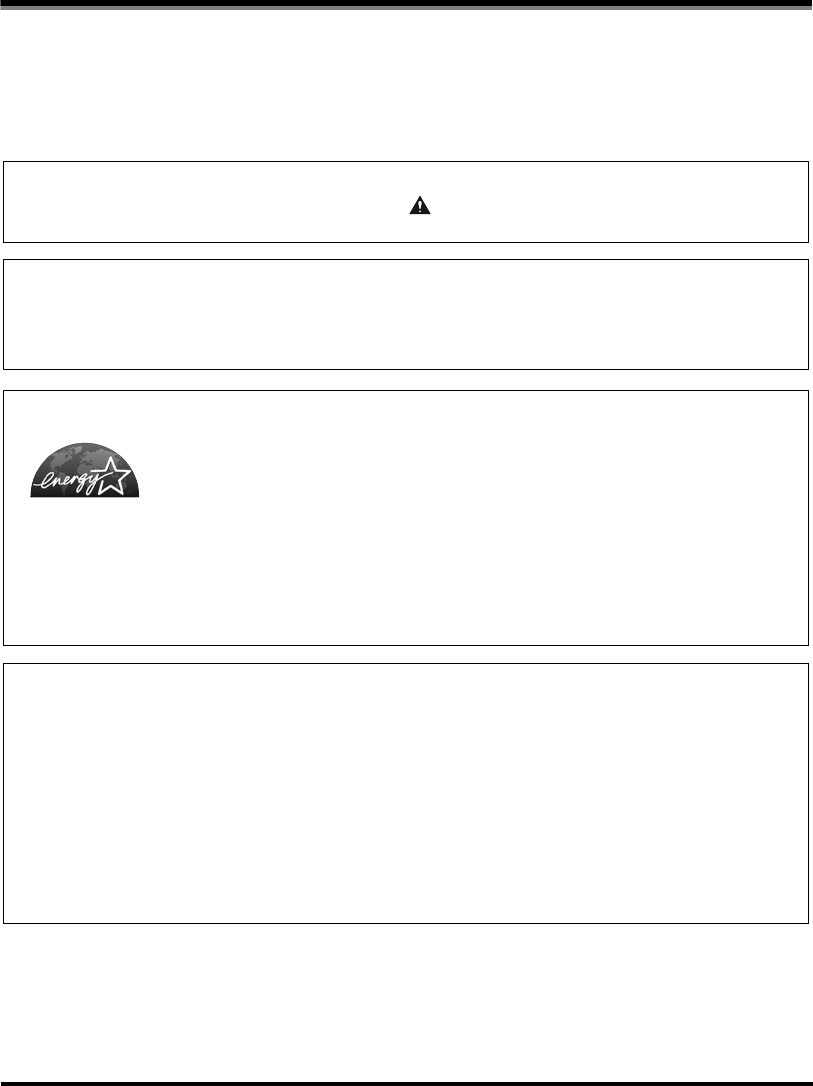
•Do not damage or modify the power cord. Also, do not place heavy objects on the power cord,
or pull on or excessively bend it, as this could cause electrical damage and result in a fire or
electrical shock.
•Do not insert or unplug the power plug with wet hands, as this may result in electrical shock.
•Do not plug the machine into a multi-plug power strip, as this may cause a fire or electrical
shock.
E1L_US_U_.book-INDEX Page xvi Wednesday, May 23, 2001 11:40 PM
Safety Considerations
xvii
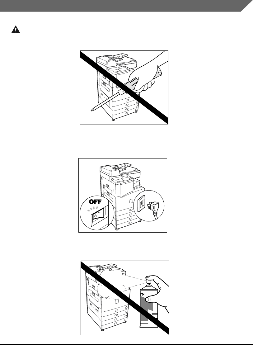
•Do not bundle up or tie the power cord in a knot, as this may result in a fire or electrical shock.
•Insert the power cord completely into the outlet, as failure to do so may result in a fire or
electrical shock.
•Do not use power cords other than the provided power cord, as this may result in a fire or
electrical shock.
•As a general rule, do not use an extension cord. Using an extension cord may result in a fire or
electrical shock. If an extension cord must be used, however, untie the cord binding and insert
the power plug completely into the extension cord outlet to ensure a firm connection between
the power and the extension cord.
E1L_US_U_.book-INDEX Page xvii Wednesday, May 23, 2001 11:40 PM

Safety Considerations xviii
•If the breaker drops to the OFF position when you turn on the power switch or when the copier
is already ON, do not push the breaker back to the ON position. Doing so may lead to a fire,
electrical shock, smoke, or the tripping of other breakers in the facility. When this happens,
unplug the power plug immediately and contact your service representative.
CAUTION
•Do not use power supplies with voltages other than 120 V AC, as this may result in a fire or
electrical shock.
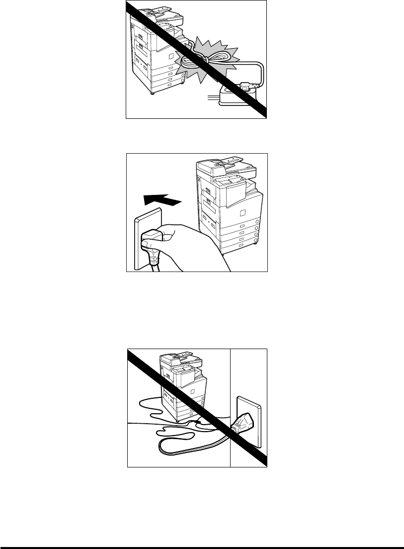
•Always grasp the plug portion when unplugging the power plug. Pulling on the power cord may
expose or snap the core wire, or otherwise damage the power cord. If the cord is damaged, this
could cause an electrical leak and result in a fire or electrical shock.
•Leave sufficient space around the power plug so that it can be unplugged easily. If objects are
placed around the power plug, you will be unable to unplug it in an emergency.
•Unplug the power plug for safety when the machine will not be used for a prolonged period of
time, for example, during consecutive holidays.
E1L_US_U_.book-INDEX Page xviii Wednesday, May 23, 2001 11:40 PM
Safety Considerations
xix
Handling
WARNING
•Do not attempt to disassemble or modify the machine. There are high-temperature and high-
voltage components inside the machine which may result in a fire or electrical shock.
•If the machine makes strange noises, or emits smoke, heat or unusual smells, immediately turn
off the main power switch and unplug the power plug from the outlet. Then, contact your
service representative. Continued use of the machine in this condition may result in a fire or
electrical shock.
•Do not use highly flammable sprays near the machine. If gas from these sprays comes into
contact with the electrical components inside the machine, this may result in a fire or electrical
shock.
E1L_US_U_.book-INDEX Page xix Wednesday, May 23, 2001 11:40 PM

Safety Considerations xx
•When moving the machine, first turn off the power switch, and then unplug the power plug.
Failure to do so will damage the power cord which may cause a fire or electrical shock.
•Do not drop paper clips, staples, or other metal objects inside the machine. Also, do not spill
water, liquids, or flammable substances (alcohol, benzene, paint thinner, etc.) inside the
machine. If these items come into contact with a high-voltage area inside the machine, this may
result in a fire or electrical shock. If these items are dropped or spilled inside the machine,
immediately turn off the main power switch and unplug the power plug from the socket. Then,
contact your service representative.
CAUTION
•Close the Feeder gently to avoid catching your hand, as this may result in personal injury.
E1L_US_U_.book-INDEX Page xx Wednesday, May 23, 2001 11:40 PM
Safety Considerations
xxi
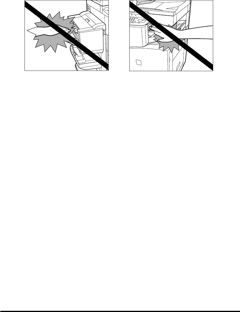
•Do not touch the finisher while the machine is printing, as this may result in personal injury.
•Do not place your hand in the part of the tray where stapling is performed while a finisher is
attached, as this may result in personal injury.
Saddle Finisher-G1 Finisher-J1
E1L_US_U_.book-INDEX Page xxi Wednesday, May 23, 2001 11:40 PM

Safety Considerations xxii
Maintenance and Inspections
WARNING
•When cleaning the machine, first turn off the main power switch and unplug the power plug.
Failure to observe these steps may result in a fire or electrical shock.
•Clean the machine using a firmly wrung-out cloth dampened with a mild cleansing detergent. Do
not use alcohol, benzene, paint thinner, or other flammable substances. If flammable
substances come into contact with a high-voltage area inside the machine, this may result in a
fire or electrical shock.
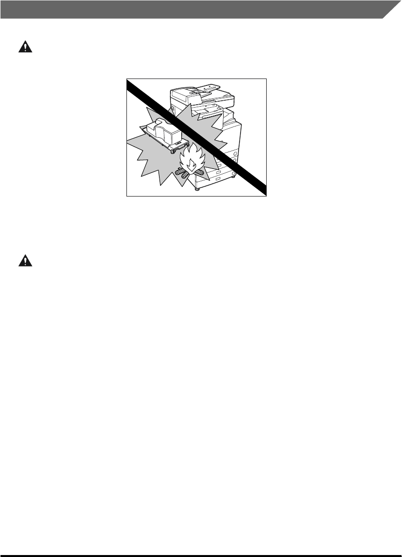
•Do not throw used toner cartridges into open flames, as this may ignite the toner remaining
inside the cartridges and result in burns or a fire.
E1L_US_U_.book-INDEX Page xxii Wednesday, May 23, 2001 11:40 PM
Safety Considerations
xxiii
CAUTION
•Unplug the power plug from the outlet at least once a year, and clean the area around the base
of the plug’s metal pins to ensure all dust is removed. If dust accumulates in this area, it may
result in a fire.
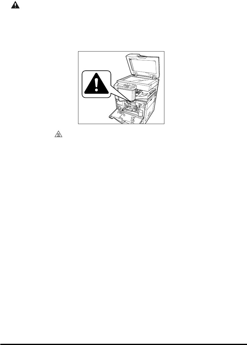
•There are some areas inside the machine which are subject to high voltages and high
temperatures. Take adequate precautions when performing internal inspections to avoid burns
or electrical shock.
•The symbol inside the machine indicates that the area is subject to high temperature, and
should not be touched without care.
•When removing jammed paper, or when inspecting the inside of the machine, do not allow
necklaces, bracelets, or other metal objects to touch the inside of the machine, as this may
result in burns or electrical shock.
•When removing paper which has become jammed inside the machine, take care not to allow the
toner on the jammed paper to come into contact with your hands or clothing, as this will dirty
your hands or clothing. If they become dirty, wash them immediately with cold water. Washing
with warm water will set the toner and make it impossible to remove the toner stains.
•When removing paper which has become jammed inside the machine, remove the jammed
paper gently to prevent the toner on the paper from scattering and entering your eyes or mouth.
If toner enters your eyes or mouth, wash immediately with cold water and consult a physician.
•When loading paper or removing jammed originals or paper, take care not to cut your hands on
the edges of the original or paper.
•When removing a used toner cartridge from the toner supply port, remove the cartridge
carefully to prevent toner from scattering and entering your eyes or mouth. If toner enters your
eyes or mouth, wash immediately with cold water and consult a physician.
E1L_US_U_.book-INDEX Page xxiii Wednesday, May 23, 2001 11:40 PM
Safety Considerations xxiv
Consumables
WARNING
•Do not throw toner cartridges into open flames, as this may cause the toner to ignite and result
in burns or a fire.
•Do not store toner cartridges or paper in places exposed to open flames, as this may cause the
toner or paper to ignite and result in burns or a fire.
•When discarding the toner cartridges, put the cartridges in a bag to prevent the toner from
scattering, and dispose of it in a non-flammable way.
CAUTION
•Keep toner and other consumables out of the reach of small children. If these items are
ingested, consult a physician immediately.
E1L_US_U_.book-INDEX Page xxiv Wednesday, May 23, 2001 11:40 PM

Safety Considerations
xxv
Warning Indications
WARNING
•The laser unit inside the machine emits laser light. Under no circumstances open the cover of
the laser unit or remove the label attached to the cover. If the laser light escapes from the
machine, exposure may cause serious damage to your eyes.
DANGER- Invisible laser radiation when opening the cover,
removing developing assembly, or cartridges.
AVOID DIRECT EXPOSURE TO BEAM.
CAUTION-INVISIBLE LASER RADIATION WHEN OPENING
THE COVER, REMOVING DEVELOPING ASSEMBLY.
AVOID EXPOSURE TO BEAM.
ATTENTION
-
RAYONNEMENT LASER INVISIBLE EN CAS D OUVERTURE DU COUVERCLE.
DU D MONTAGE DE L ENSEMBLE DE D VELOPPEMENT.
EVITER TOUTE EXPOSITION DIRECTE AVEC LE FAISCEAU.
VORSICHT -
UNSICHTBARE LASERSTRAHLUNG, WENN ABDECKUNG GE FFNET.
NICHT DEM STRAHL AUSSETZEN.
ATTENZIONE
-
EMISSIONE DI UN RAGGIO LASER INVISIBILE A SEGUITO DELL APERTURA
DELLA COPERTURA O DELLA RIMOZIONE DEL GRUPPO DI SVILUPPO.
EVITARE L ESPOSIZIONE DIRETTA AL RAGGIO LASER.
PRECAUCI N
-
RADIACI N L SER INVISIBLE EN CASO DE ABRIR LA CUBIERTA Y RETIRAR
LA UNIDAD REVELADORA. EVITE LA EXPOSICI N AL HAZ L SER.
VARO! -
AVATTAESSA KEHITYSYKSIK N POISSAOLLESSA OLET ALTTINA
NKYM TT M LLE LASERS TEILYLLE. L KATSO S TEESEEN.
VARNING! -
OSYNLIG LASERSTR LNING N R DENNA DEL R PPNAD OCH.
FRAMKALLAREN RURTAGEN. BETRAKTA EJ STR LEN.
ADVARSEL! -
USYNLIG LASER STR LING, N R DfiKSLET BNES FOR AT FJERNE
FRAMKALLALDEREN. UNDG AT BLIVE RAMT AFSTR LEN.
ADVARSEL -
USYNLIG LASERSTR LING N R DEKSELEΠPNES OG.
LASERENHETEN TASUT. IKKE SE DIREKTE P STR LEN.
DANGER- Invisible laser radiation when open.
AVOID DIRECT EXPOSURE TO BEAM.
CAUTION-INVISIBLE LASER RADIATION WHEN OPEN.
AVOID EXPOSURE TO BEAM.
ATTENTION
-
RAYONNEMENT LASER INVISIBLE EN CAS D OUVERTURE.
EXPOSITION DANGEREUSE AU FAISCEAU.
VORSICHT -
UNSICHTBARE LASERSTRAHLUNG, WENN ABDECKUNG GE FFNET.
NICHT DEM STRAHL AUSSETZEN.
ATTENZIONE
-
RADIAZIONE LASER INVISIBLE IN CASO DI APERTURA.
EVITARE L ESPOSIZIONE AL FASCIO.
PRECAUCION
-
RADIACION LASER INVISIBLE CUANDO SE ABRE.
EVITAR EXPONERSE AL RAYO.
VARO! -
AVATTAESSA OLET ALTTIINA N KYM TT M LLE
LASERS TEILYLLE. L KATSO S TEESEEN.
VARNING! -
OSYNLIG LASERSTR LNING NAR DENNA DEL R PPNAD.
BETRAKTA EJ STR LEN.
ADVARSEL! -
USYNLIG LASER STR LING, N R DENNE ER BEN.
UNDG BESTR LING.
ADVARSEL -
USYNLIG LASERSTR LING N R DEKSEL PNES.
UNNG EKSPONERING FOR STR LEN.
E1L_US_U_.book-INDEX Page xxv Wednesday, May 23, 2001 11:40 PM

Periodic Inspection of the Breaker xxvi
Periodic Inspection of the Breaker
This machine has a breaker that detects excess current or leakage current. Be sure to test
the breaker once or twice a month using the following procedure.
IMPORTANT
•
Make sure that the main power is turned on, and the machine is neither printing nor scanning before
starting a periodic inspection of the breaker.
•
If a malfunction occurs after a periodic inspection, contact your service representative.
1
Push the test button with the tip of a ball-point pen, or similar object.
NOTE
•
The breaker is located near the power cord.
2
The breaker lever automatically goes to OFF (“ ” side). Confirm
that the power is cut OFF.
ON
I side)(
OFF
side)(
E1L_US_U_.book-INDEX Page xxvi Wednesday, May 23, 2001 11:40 PM

Periodic Inspection of the Breaker
xxvii
IMPORTANT
•
Do not use the test button to turn the power ON and OFF.
•
If the breaker lever does not go to OFF (“ ” side), repeat step 1.
•
If the breaker lever does not go to OFF (“ ” side), despite carrying out the above procedure
two or three times, contact your service representative.
3
Once you have confirmed that the above operation takes place,
press the main power switch to OFF ( side).
4
Move the breaker lever to ON (“I” side).
5
Press the main power switch to ON (“I” side).
ON
I side)(
OFF
side)(
ON
I side)(
OFF
side)(
E1L_US_U_.book-INDEX Page xxvii Wednesday, May 23, 2001 11:40 PM

Periodic Inspection of the Breaker xxviii
6
Fill in the check sheet for the periodic inspection of the breaker,
located at the end of this manual.
OFF
side)(
ON
I side)(
E1L_US_U_.book-INDEX Page xxviii Wednesday, May 23, 2001 11:40 PM

Legal Limitations on Scanner Usage and the Use and Printing of Scanned Images
xxix
Legal Limitations on Scanner Usage and the Use
and Printing of Scanned Images
Using your scanner to reproduce certain documents, and the printing and use of such
reproductions, may be prohibited by law and may result in criminal and/or civil liability. A non-
exhaustive list of these document is set forth below. This list is intended to be a guide only. If
you are uncertain of the legality of using your scanner to reproduce any particular document,
and/or the printing and use of such reproductions, you should consult in advance with your
legal advisor for guidance.
•Paper money
•Travelers Cheques
• Money Orders
•Food Stamps
• Certificates of Deposit
•Passports
•Postage Stamps (canceled or uncanceled)
• Immigration Papers
• Identifying badges or insignias
• Internal Revenue Stamps (canceled or uncanceled)
• Selective Service or draft papers
• Bonds or other certificates of indebtedness
• Checks or drafts drawn by Governmental agencies
• Stock Certificates
• Motor Vehicle Licenses and Certificates of Title
• Copyrighted Works/Works of Art without Permission of Copyright Owner
E1L_US_U_.book-INDEX Page xxix Wednesday, May 23, 2001 11:40 PM
Operation of the Machine and Terms Used in This Manual xxx
Operation of the Machine and Terms Used in This
Manual
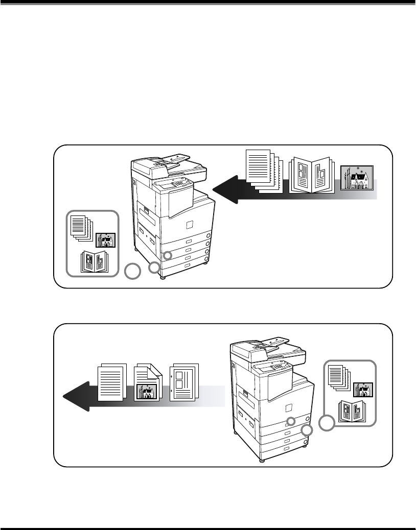
This machine makes effective use of memory in order to perform print operations efficiently.
For example, as soon as the machine has scanned the original that you want to copy, it can
immediately scan the next person’s original. You can also print from this machine, using a
function other than the Copy function. In this machine, these operations take place in a
complex way, so that not only copies, but also various kinds of prints may sometimes have to
wait their turn before they can be output.
To avoid confusion when reading this manual, the terms “scanning,” “printing,” and “copying”
used throughout this manual are defined as set out below. There are some cases in which
the scanning of an original when making a copy, and the process of making a print, are
described separately.
Scanning
Scanning an original to be copied,
or scanning an original to be stored
as data in a box.
Printing
Copying
Prnting data scanned from an original, followed by finishing (stapling, etc.).
Outputting a copy, outputting data stored in a mail
box, or outputting data sent from a personal
computer to the machine.
E1L_US_U_.book-INDEX Page xxx Wednesday, May 23, 2001 11:40 PM

Operation of the Machine and Terms Used in This Manual
xxxi
E1L_US_U_.book-INDEX Page xxxi Wednesday, May 23, 2001 11:40 PM

CHAPTER
1-1
1
Before You Start Using
This Machine
This chapter describes what you should know before using this machine, such as main
features, parts and their functions, how to turn on the main power, and so on.
About the Installation Location and Handling . . . . . . . . . . . . . . . . . . . . . . . . . . . . . . . . . .1-3
Installation Precautions . . . . . . . . . . . . . . . . . . . . . . . . . . . . . . . . . . . . . . . . . . . . . . . . . . . . . . . .1-3
Handling Precautions . . . . . . . . . . . . . . . . . . . . . . . . . . . . . . . . . . . . . . . . . . . . . . . . . . . . . . . . . .1-7
What the imageRUNNER 3300/2800/2200 Series Can Do . . . . . . . . . . . . . . . . . . . . . . .1-9
Switching the Functions Indicated on the Touch Panel Display. . . . . . . . . . . . . . . . . . . . . . . . . .1-9
Setting Specifications to Suit Your Needs . . . . . . . . . . . . . . . . . . . . . . . . . . . . . . . . . . . . . . . . . .1-9
Functions That Conserve Power Consumption . . . . . . . . . . . . . . . . . . . . . . . . . . . . . . . . . . . . .1-10
Checking, Changing, and Canceling Print Jobs . . . . . . . . . . . . . . . . . . . . . . . . . . . . . . . . . . . .1-11
Displaying a Guide Screen . . . . . . . . . . . . . . . . . . . . . . . . . . . . . . . . . . . . . . . . . . . . . . . . . . . .1-12
Reading the Messages from the System Manager . . . . . . . . . . . . . . . . . . . . . . . . . . . . . . . . . .1-13
Using Other Useful Functions . . . . . . . . . . . . . . . . . . . . . . . . . . . . . . . . . . . . . . . . . . . . . . . . . .1-14
Parts and Their Functions. . . . . . . . . . . . . . . . . . . . . . . . . . . . . . . . . . . . . . . . . . . . . . . .1-17
External View . . . . . . . . . . . . . . . . . . . . . . . . . . . . . . . . . . . . . . . . . . . . . . . . . . . . . . . . . . . . . . .1-17
Internal View . . . . . . . . . . . . . . . . . . . . . . . . . . . . . . . . . . . . . . . . . . . . . . . . . . . . . . . . . . . . . . . .1-19
Control Panel Parts and Functions . . . . . . . . . . . . . . . . . . . . . . . . . . . . . . . . . . . . . . . . . . . . . . .1-20
Checking the Counter. . . . . . . . . . . . . . . . . . . . . . . . . . . . . . . . . . . . . . . . . . . . . . . . . . .1-22
Main Power and Control Panel Power . . . . . . . . . . . . . . . . . . . . . . . . . . . . . . . . . . . . . .1-23
How to Turn On the Main Power. . . . . . . . . . . . . . . . . . . . . . . . . . . . . . . . . . . . . . . . . . . . . . . . .1-23
Control Panel Power Switch . . . . . . . . . . . . . . . . . . . . . . . . . . . . . . . . . . . . . . . . . . . . . . . . . . . .1-26
The System Settings of This Machine . . . . . . . . . . . . . . . . . . . . . . . . . . . . . . . . . . . . . .1-27
Using the Touch Panel Display . . . . . . . . . . . . . . . . . . . . . . . . . . . . . . . . . . . . . . . . . . . .1-28
Frequently-used Keys on the Touch Panel Display . . . . . . . . . . . . . . . . . . . . . . . . . . . . . . . . . .1-28
Touch Panel Key Display . . . . . . . . . . . . . . . . . . . . . . . . . . . . . . . . . . . . . . . . . . . . . . . . . . . . . .1-29
Adjusting the Brightness of the Touch Panel Display. . . . . . . . . . . . . . . . . . . . . . . . . . . . . . . . .1-30
Entering Characters from the Touch Panel Display . . . . . . . . . . . . . . . . . . . . . . . . . . . .1-31
Entering Alphabet Characters . . . . . . . . . . . . . . . . . . . . . . . . . . . . . . . . . . . . . . . . . . . . . . . . . .1-31
Entering Special Characters . . . . . . . . . . . . . . . . . . . . . . . . . . . . . . . . . . . . . . . . . . . . . . . . . . .1-33
Entering in Inches. . . . . . . . . . . . . . . . . . . . . . . . . . . . . . . . . . . . . . . . . . . . . . . . . . . . . . . . . . . .1-35
Entering the Department ID and Password . . . . . . . . . . . . . . . . . . . . . . . . . . . . . . . . . .1-36
Operations After Turning the Power On . . . . . . . . . . . . . . . . . . . . . . . . . . . . . . . . . . . . . . . . . . .1-36
Operations After Using Copy Functions. . . . . . . . . . . . . . . . . . . . . . . . . . . . . . . . . . . . . . . . . . .1-38
Placing Originals. . . . . . . . . . . . . . . . . . . . . . . . . . . . . . . . . . . . . . . . . . . . . . . . . . . . . . .1-39
E1L_US_U_.book-INDEX Page 1 Wednesday, May 23, 2001 11:40 PM

1. Before You Start Using This Machine
1-2
Before You Start Using This Machine
1
Orientation of Originals . . . . . . . . . . . . . . . . . . . . . . . . . . . . . . . . . . . . . . . . . . . . . . . . . . . . . . . 1-40
Placing an Original on the Platen Glass . . . . . . . . . . . . . . . . . . . . . . . . . . . . . . . . . . . . . . . . . . 1-41
Placing Originals in the Feeder (DADF-H1) . . . . . . . . . . . . . . . . . . . . . . . . . . . . . . . . . . . . . . . 1-43
Making Prints Using the Stack Bypass. . . . . . . . . . . . . . . . . . . . . . . . . . . . . . . . . . . . . .1-46
Using the Stack Bypass While Reserving Print Jobs . . . . . . . . . . . . . . . . . . . . . . . . . . . . . . . . 1-54
Multi-function Operation . . . . . . . . . . . . . . . . . . . . . . . . . . . . . . . . . . . . . . . . . . . . . . . . .1-57
Available Paper Stock. . . . . . . . . . . . . . . . . . . . . . . . . . . . . . . . . . . . . . . . . . . . . . . . . . .1-59
E1L_US_U_.book-INDEX Page 2 Wednesday, May 23, 2001 11:40 PM
About the Installation Location and Handling 1-3
Before You Start Using This Machine
1
About the Installation Location and Handling
Installation Precautions
Avoid Installing the Machine in the Following Locations
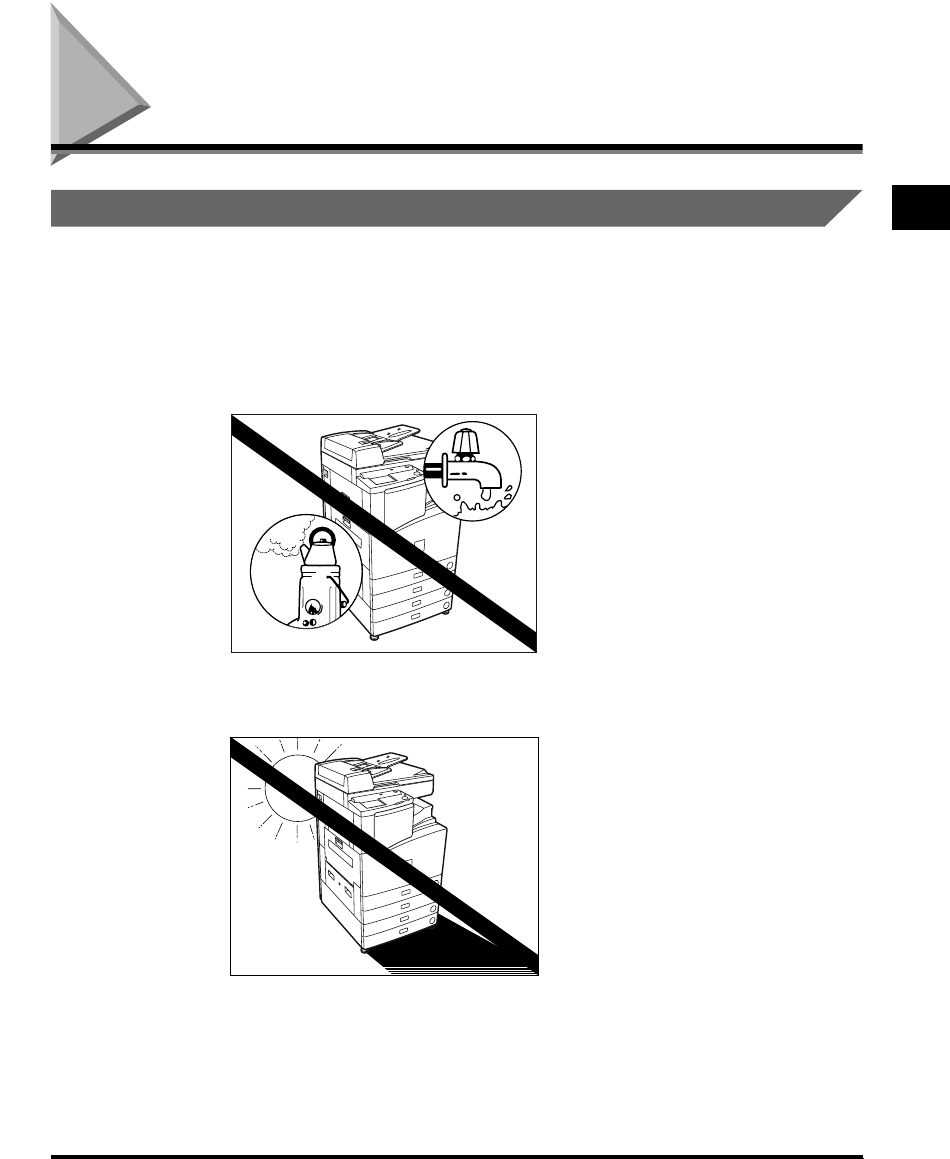
■Avoid locations which are subject to extremes of temperature and humidity: either
low or high.
For example, avoid installing the machine near water faucets, hot water heaters,
humidifiers, air conditioners, heaters or stoves.
■Avoid installing the machine in direct sunlight.
If this is unavoidable, shade the machine, using curtains.
E1L_US_U_.book-INDEX Page 3 Wednesday, May 23, 2001 11:40 PM

1
About the Installation Location and Handling
1-4
Before You Start Using This Machine
■Avoid poorly ventilated locations.
During use, the machine generates ozone. However, the amount of ozone generated is
not enough to affect the human body. Nevertheless, if the machine is used for a prolonged
period of time in a poorly ventilated room, or when making a large quantity of prints, be
sure to ventilate the room to make the working environment as comfortable as possible.
■Avoid locations where a considerable amount of dust accumulates.
■Avoid locations where ammonia gas is emitted.
■Avoid locations near volatile, flammable materials, such as alcohol or paint thinner.
■Avoid locations which are subject to vibration.
For example, avoid installing the machine on unstable floors or stands.
E1L_US_U_.book-INDEX Page 4 Wednesday, May 23, 2001 11:40 PM
1
About the Installation Location and Handling 1-5
Before You Start Using This Machine
■Avoid exposing the machine to rapid changes in temperature.
If the room in which the machine is installed is rapidly heated from a low temperature,
condensation may form inside the machine. This can adversely affect print quality or result
in an inability to obtain print images.
■Avoid installing the machine near computers or other precision electronic
equipment.
Electrical interference and vibrations generated by the machine during printing can
adversely affect the operation of such equipment.
■Avoid installing the machine near televisions, radios, or similar electronic
equipment.
The machine might interfere with sound and picture signal reception, etc. Plug the
machine into a dedicated power outlet and maintain as much space as possible between
the machine and other electronic equipment.
■About the machine’s fixing stoppers.
Do not remove the machine’s fixing stoppers after the machine has been installed.
If you put weight on the front of the machine while the paper drawers or units within the
machine are pulled out all the way, the machine might fall forward. To prevent this from
happening, make sure that the machine's fixing stoppers are set in place.
E1L_US_U_.book-INDEX Page 5 Wednesday, May 23, 2001 11:40 PM

1
About the Installation Location and Handling
1-6
Before You Start Using This Machine
Select a Safe Power Supply
■Plug the machine into a 120V AC outlet.
■Do not plug other electrical equipment into the outlet in which the machine is
connected.
■Do not plug the machine into a multi-plug power strip. Doing so might cause a fire.
■The power cable may become damaged if it is often stepped on or if heavy objects
are placed on it. Continued use of a damaged power cable can lead to an accident.
Provide Adequate Installation Space
■Provide enough space on each side of the machine for unrestricted operation.
26-3/4"
(
678mm
)
57-7/8"
(1469mm)
4" or more (100 mm)
32-3/4"
(830 mm)
4" or more (100 mm)
26-3/4"
(678 mm)
■
When Finisher-J1 is
attached
■
When Saddle Finisher-G1 is
attached
E1L_US_U_.book-INDEX Page 6 Wednesday, May 23, 2001 11:40 PM
1
About the Installation Location and Handling 1-7
Before You Start Using This Machine
Moving the Machine
■If you intend to move the machine, contact your service representative beforehand.
Handling Precautions
■Do not attempt to disassemble or modify the machine.
■Some parts inside the machine are subject to high voltages and temperatures. Take
adequate precaution when inspecting the inside of the machine. Do not carry out
any inspections not described in this manual.
■Be careful not to drop any foreign objects, such as paper clips or staples, inside the
machine. If a foreign object comes into contact with electrical parts inside the
machine, it might cause a short circuit and result in a fire or an electrical shock.
E1L_US_U_.book-INDEX Page 7 Wednesday, May 23, 2001 11:40 PM

1
About the Installation Location and Handling
1-8
Before You Start Using This Machine
■If there is unusual noise or smoke, immediately turn the main power switch off,
then call your service representative. Using the machine in this state might cause a
fire or an electric shock. Also, avoid placing objects around the plug so that the
machine can be unplugged whenever necessary.
■Do not turn the main power switch off or open the front door during operation of
the machine. This might result in paper jams.
■If the machine will not be used for a prolonged period of time, for example, during
the night, turn the control panel power switch off.
■There may be an accident or a defect with the hard disk in the machine, causing
loss, destruction, or alternation of data received or stored on the hard disk. You are
recommended not to store data on the hard disk without having copies or print-
outs of such data outside the machine.
CAUTION
•CANON RECOMMENDS THAT DATA STORED ON THE PRODUCT’S HARD DISK DRIVE BE
DUPLICATED OR BACKED UP TO PREVENT ITS LOSS IN THE EVENT OF FAILURE OR
OTHER MALFUNCTION OF THE HARD DISK DRIVE. NEITHER CANON NOR ANY SERVICE
PROVIDER WILL BE LIABLE FOR DAMAGES FROM LOSS OF DATA STORED ON THE
PRODUCT’S HARD DISK DRIVE (SEE THE TERMS OF THE PRODUCT’S LIMITED
WARRANTY FOR MORE DETAILS).
E1L_US_U_.book-INDEX Page 8 Wednesday, May 23, 2001 11:40 PM
What the imageRUNNER 3300/2800/2200 Series Can Do 1-9
Before You Start Using This Machine
1
What the imageRUNNER 3300/2800/2200 Series
Can Do
Most operations of this machine are done from the touch panel display. By pressing the keys
following the messages in the touch panel display, you can utilize almost all of the functions
of this machine.
Switching the Functions Indicated on the Touch Panel
Display
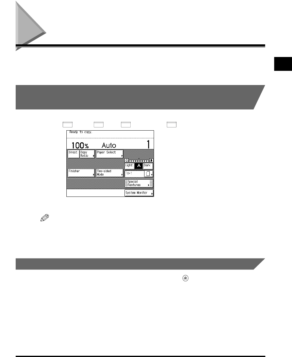
After the power is turned on, the following screen appears on the touch panel display. You
can use (Copy), (Fax), (Mail Box), or (Scan) to change functions.
NOTE
•
You can set the initial screen (the first screen shown when the machine is turned on) from the
Additional Functions screen. The initial screen can be the Copy, Fax, Mail Box, or System Monitor
screen.
Setting Specifications to Suit Your Needs
The Additional Functions screen appears when you press (Additional Functions). The
Additional Functions screen enables you to make common settings related to many functions
of the machine, as well as setting specific functions to suit your needs. For details of settings
not explained in this manual, see the following manuals:
Copy Settings ........................................The Copying Guide
Custom Fax Settings...............................The Facsimile Guide
Mail Box Settings....................................The Mail Box Function Guide
Printer Settings.......................................The PS/PCL Printer Guide
COPY FAX
MAIL BOX
SCAN
The Basic Features screen
E1L_US_U_.book-INDEX Page 9 Wednesday, May 23, 2001 11:40 PM

1
What the imageRUNNER 3300/2800/2200 Series Can Do
1-10
Before You Start Using This Machine
NOTE
•
Settings made in the Additional Functions screen are not changed even when you press
(Reset).
•
For details of how to make custom settings, see ’Selecting and Storing Settings to Suit Your Needs,’
in Chapter 3.
•
For details of the System Settings, see ‘System Manager Settings,’ in Chapter 4.
•
When the FAX Board is not attached, “Report Settings,” “Custom Fax Settings,” and
“Communications Settings” are not displayed.
•
When the Printer Kit is not attached, “Report Settings,” “Printer Settings,” “Network Settings,”
“Remote UI On/Off,” and “Clear Message Board” are not displayed.
•
When the Network Interface Adapter is not attached, “Report Settings,” “Network Settings,” “Remote
UI On/Off,” and “Clear Message Board” are not displayed.
•
For details of the Custom Fax Settings, Printer Settings, Report Settings, Communications Setting,
Network Settings and Remote UI On/Off functions, refer to the instruction manual attached to FAX
Board, Printer Kit, or Network Interface Adapter.
•
”Auto Offline” is displayed only when the network scan Kit is attached.
Functions That Conserve Power Consumption
You can conserve power consumption efficiently using the following functions when the
machine is not operated.
NOTE
•
The touch panel display turns off when the machine enters one of these functions.
•
You can print data sent from a computer even when the machine enters one of these functions.
■Sleep Mode
You can set the machine to enter the Sleep mode whenever you desire, by pressing the
control panel power switch. To reactivate the machine, press the control panel power
switch again.
The Additional Functions screen The System Settings screen
E1L_US_U_.book-INDEX Page 10 Wednesday, May 23, 2001 11:40 PM
1
What the imageRUNNER 3300/2800/2200 Series Can Do 1-11
Before You Start Using This Machine
NOTE
•
Turn the control panel power switch off when not using your machine for a prolonged period of time,
for example, at night.
•
The Auto Sleep Time can be set from 10 seconds to 4 hours. The default setting is “2 minutes.” (See
‘Setting the Time Taken to Initiate Auto Sleep After Finishing Operations,’ on p. 3-33.)
■Daily Timer
At the time and day of the week set with the daily timer, the control panel power switch
automatically turns off. To reactivate the machine, press the control panel power switch.
NOTE
•
The Daily Timer settings are in the range from Sunday to Saturday and from 00:00 to 23:59. (See
‘Setting the Time that the Unit’s Power Turns Off on Different Days of the Week,’ on p. 3-36.)
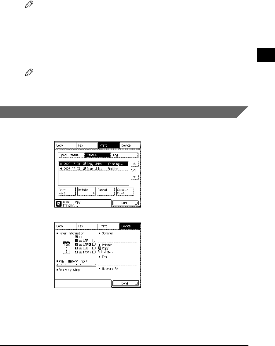
Checking, Changing, and Canceling Print Jobs
Using the System Monitor screen, you can check the status of a printing document, cancel
printing, or specify the printing priority.
The System Monitor screen
E1L_US_U_.book-INDEX Page 11 Wednesday, May 23, 2001 11:40 PM

1
What the imageRUNNER 3300/2800/2200 Series Can Do
1-12
Before You Start Using This Machine
NOTE
•
For a description of functions, see ‘Checking Job and Device Status,’ in Chapter 2.
•
The status of each icon displayed in the screen is as follows:
-: Copy job
-: Printer job
-: Fax job
-: Box job
-: Error
-: Paper jam
-: Add toner
Displaying a Guide Screen
Pressing (Guide) brings up a guide screen with information about the various features
that are available with your machine.
■Usage Guide
Pressing (Guide) after selecting a function brings up a guide screen with an
explanation for that function. Use this guide function if you do not understand how to use
the mode you are setting.
(In this example, the Margin mode has been selected.)
If you press (Guide) while setting “Margin,” the touch panel display changes to the
Guide Function screen shown below. To return to the display for “Margin,” press “Done.”
The Guide Function screen
E1L_US_U_.book-INDEX Page 12 Wednesday, May 23, 2001 11:40 PM

1
What the imageRUNNER 3300/2800/2200 Series Can Do 1-13
Before You Start Using This Machine
■Guide Menu
This machine supports many functions.
To find the right function for your particular needs or to find a simple description of a
function, press (Guide) while the Basic Features screen or Special Features screen is
displayed.
The Guide Menu screen appears in the touch panel display as shown below.
Example: When copying photo originals:
Press “Various originals.”
You can display simple explanations of the various types of originals using “▼” or “▲.”
Press “Done” to return to the Various Originals Menu screen. To return the display to the
Guide Menu, press “Guide Menu.”
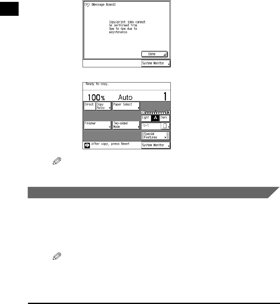
Reading the Messages from the System Manager
A message board is used to indicate messages on the touch panel display from the system
manager to users of this machine, through the Remote UI feature.
NOTE
•
The message board can be used when the network is connected.
Types of message board
The following three types of message board are available:
•A message board without “Done.”
The Guide Menu screen
Message Board
E1L_US_U_.book-INDEX Page 13 Wednesday, May 23, 2001 11:40 PM
1
What the imageRUNNER 3300/2800/2200 Series Can Do
1-14
Before You Start Using This Machine
•A message board with “Done.”
- If you press “Done” and close the message board, you can perform a normal operation.
The message appears again when the main power is turned back on, or after Auto Clear
has taken place. You can set the Auto Clear Time from 1 to 9 minutes, in one-minute
increments. You can also cancel this function. (See ‘Setting the Time Taken for the Display
to Return to the Basic Features Screen After Finishing Operations,’ on p. 3-34.)
•A message board, in which the message appears in the Job/Print monitor area.
NOTE
•
For details of how to erase the message board, see ‘Erasing the Message Board (Clear Message
Board),’ on p. 4-25.
Using Other Useful Functions
Other useful functions are as follows:
■Auto Drawer Switching Function
If a paper drawer runs out of paper during printing, the machine automatically locates
another paper drawer loaded with the same size paper, and begins feeding paper from
that paper drawer.
NOTE
•
You can set whether or not a paper drawer is subject to Auto Drawer Switching for each function. The
default setting is “Off” for the stack bypass and “On” for the other paper drawers. (See ‘Setting a
Paper Drawer for Auto Paper Selection/Auto Drawer Switching,’ on p. 3-13.)
E1L_US_U_.book-INDEX Page 14 Wednesday, May 23, 2001 11:40 PM

1
What the imageRUNNER 3300/2800/2200 Series Can Do 1-15
Before You Start Using This Machine
■Auto Clear Function
If the machine is not operated for a period of about two minutes after prints have been
made or a key operation performed, it automatically returns the settings to the Standard
mode.
NOTE
•
You can set the Auto Clear Time from 0 to 9 minutes, in one-minute increments. The default setting is
“2 minutes.” (See ‘Setting the Time Taken for the Display to Return to the Basic Features Screen
After Finishing Operations,’ on p. 3-34.)
■Copy Waiting Time Display Function
When you turn on the Job Duration Display from the Additional Functions screen, the
display shows the copy waiting time depending on the selected copy mode.
NOTE
•
The job duration time is not displayed for the Transparency Interleaving, Cover/Sheet Insertion,
Different Size Originals, Rotate Collating, and Rotate Grouping modes, or when the copy waiting
time is less than one minute. (See the Copying Guide.)
■Paper Supply Indicator Function
This function shows the remaining amount of paper in each paper drawer when you select
the paper source (see the Copying Guide and the Mail Box Function Guide) or when
paper in one paper drawer has run out during printing.
There are four different indicators as shown below.
Display Remaining paper
Paper drawer is approximately 50% - 100% full.
Paper drawer is approximately 10% - 50% full.
Paper drawer is less than approximately 10% full.
Paper drawer is empty.
Display when selecting paper
Paper Supply indicator
Display when paper has run out
E1L_US_U_.book-INDEX Page 15 Wednesday, May 23, 2001 11:40 PM

1
What the imageRUNNER 3300/2800/2200 Series Can Do
1-16
Before You Start Using This Machine
■Auto Rotate Function
Using parameters such as original size and zoom ratio, this function automatically rotates
the image to the most suitable position for the set paper size.
If the image does not fit on the paper even after rotation, the machine will not rotate the
image but will print it as is, with part of the image cut off.
Rotation is not performed when: the Different Size Originals, Cover/sheet Insertion,
Double Staple or Hole Punch is selected, while “Auto” paper selection is set, or when
Transparency Interleaving, XY Zoom, or Free-size paper setting is selected. (See the
Copying Guide, Mail Box Function Guide.)
■Quiet Mode
If this machine is not operated (no keys are pressed) for a certain period of time after
prints have been made or a key operation performed, the device sounds from this
machine are stopped, and the machine enters the Quiet mode.
NOTE
•
The Quiet Mode settings are in the range from 0 to 9 minutes in one-minute increments. The default
setting is “1 minute.” (See ‘Setting the Time Taken for the Unit to Quiet Down After the Last Task,’ on
p. 3-35.)
E1L_US_U_.book-INDEX Page 16 Wednesday, May 23, 2001 11:40 PM

Parts and Their Functions 1-17
Before You Start Using This Machine
1
Parts and Their Functions
External View
2
1
3
4
5
6
7
8
1
23
4
5
6
7
8
When Feeder (DADF-H1),
Finisher-J1, and Cassette
Feeding Unit-W1 are attached
When Feeder (DADF-H1), Saddle Finisher-
G1, Inner 2way Tray-A1, Cassette Feeding
Unit-W1, and Paper Deck-L1 are attached
E1L_US_U_.book-INDEX Page 17 Wednesday, May 23, 2001 11:40 PM

1
Parts and Their Functions
1-18
Before You Start Using This Machine
1 Control panel
(See ‘Control Panel Parts and Functions,’ on p. 1-
20.)
2 Feeder
3 Original supply tray
4 Original output area
5 Paper drawer 1
Holds up to 500 sheets of paper (20-lb bond (80
g/m2)). Also, the Envelope Feeder Attachment-
B1 (option) can be attached.
6 Paper drawer 2
Holds up to 500 sheets of paper (20-lb bond (80
g/m2)).
7, 8 Paper drawer 3, 4
Paper drawers of the Cassette Feeding Unit-W1.
Each paper drawer holds up to 500 sheets of
paper (20-lb bond (80g/m2)).
9 Platen glass cover
1
9
5
When Feeder (DADF-H1), Inner 2way
Tray-A1, and Copy Tray-F1 are attached When the platen glass cover is attached
6
2
1
3
4
5
6
E1L_US_U_.book-INDEX Page 18 Wednesday, May 23, 2001 11:40 PM

1
Parts and Their Functions 1-19
Before You Start Using This Machine
Internal View
1 Front cover
2 Duplexing unit
3 Toner box
4 Scanning area
5 Rear side of platen glass cover
6 Platen glass
7 Stack bypass
Feeds transparencies and non-standard size
paper stock. (See ‘Making Prints Using the Stack
Bypass,’ on p. 1-46.)
8 Main power switch
Press to the “I” side to turn the power on. (See
‘Main Power and Control Panel Power,’ on p. 1-
23.)
9 Breaker
Detects excess current or leakage current.
(See ‘Periodic Inspection of the Breaker,’ on p.
xxvi.)
0 Test button
A Upper right cover
Open this cover when clearing a paper jam.
(See ‘Clearing Paper Jams,’ on p. 6-2.)
5
7
6
4
3
2
1
A
9
0
8
E1L_US_U_.book-INDEX Page 19 Wednesday, May 23, 2001 11:40 PM
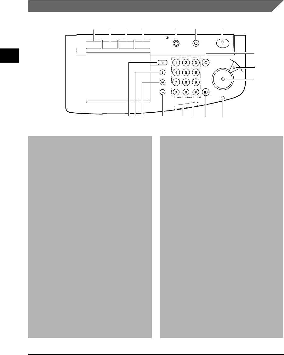
1
Parts and Their Functions
1-20
Before You Start Using This Machine
Control Panel Parts and Functions
1 COPY key
Press to use the Copy function. The Copy Basic
Features screen appears in the touch panel
display.
2 FAX key
Press to use the Fax function. The Fax Basic
Features screen appears in the touch panel
display.
3 MAIL BOX key
Press to use the Mail Box function. The Box
Selection screen appears in the touch panel
display.
4 SCAN key
Press when the network scan function is
enabled.
5 Display contrast dial
Use to adjust the brightness of the touch panel
display.
6 Counter Check key
The value of the counter is displayed in the touch
panel.
7 Control panel power switch (sub power
supply)
Press to turn the control panel ON or OFF. When
set to OFF, the machine is in the Sleep mode.
8 Clear key
Press to clear incorrectly entered values or
characters.
9 Stop key
Press to temporarily stop a scanning operation,
an output operation of the copy function, or a
sending a fax operation.
0 Start key
Press to start an operation.
A Main Power indicator
Lights when the main power is turned on.
B ID key
Press when setting the Department ID
Management function.
C Error indicator
Flashes or lights if there is trouble in the
machine. When the indicator flashes, follow the
instructions appearing on the touch panel
display. When it lights, contact your service
representative.
D Processing/Data indicator
Flashes when this machine is performing
operations, and lights when there is fax data
received job in memory.
ON / OFF
COPY FAX
MAIL BOX
SCAN
Reset Clear
Display Contrast Counter Check
Guide GHI
PRS
JKL
ABC
TUV
MNO
DEF
WXY
OPER
Additional Functions
Interrupt
Start
Power
Error
Processing/Data
Stop
1234675
8
9
0
A
B
C
D
E
FG
H
I
E1L_US_U_.book-INDEX Page 20 Wednesday, May 23, 2001 11:40 PM

1
Parts and Their Functions 1-21
Before You Start Using This Machine
E Numeric keys
Press to enter numerical values.
F Interrupt key
Press to interrupt a continuous copying job when
you need to make priority copies.
G Additional Functions key
Press to set additional functions.
H Guide key
Press to display explanations of modes or
functions in the touch panel display.
I Reset key
Press to return the settings to the Standard
mode.
E1L_US_U_.book-INDEX Page 21 Wednesday, May 23, 2001 11:40 PM

Checking the Counter
1-22
Before You Start Using This Machine
1
Checking the Counter
You can check counter totals of copy, and print jobs.
1
Press (Counter Check) on the control panel.
The counter totals are shown in the touch panel display.
Counter Check
E1L_US_U_.book-INDEX Page 22 Wednesday, May 23, 2001 11:40 PM
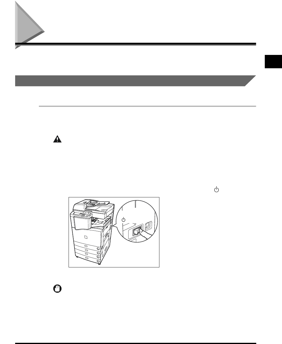
Main Power and Control Panel Power 1-23
Before You Start Using This Machine
1
Main Power and Control Panel Power
The machine is provided with two power switches, a main power switch and a control panel
power switch.
How to Turn On the Main Power
This section explains about how to turn on the main power.
1
Make sure that the power plug is firmly inserted into the power
outlet.
WARNING
•Never remove or insert the power plug with wet hands. This can cause an electrical
shock.
2
Press the power switch to ON (“ I ” side). The main power switch is
located on the right side of the machine.
When turning off the main power, press the main power switch to the “ ” side.
The main power indicator on the control panel lights.
IMPORTANT
•
If the main power indicator on the control panel does not light even though the main power
switch is ON, be sure to check the breaker to see if it is OFF.(See ‘When the Power Does Not
Turn On (Checking the Breaker),’ on p. 6-34.)
ON
I side)(
OFF
side)(
E1L_US_U_.book-INDEX Page 23 Wednesday, May 23, 2001 11:40 PM
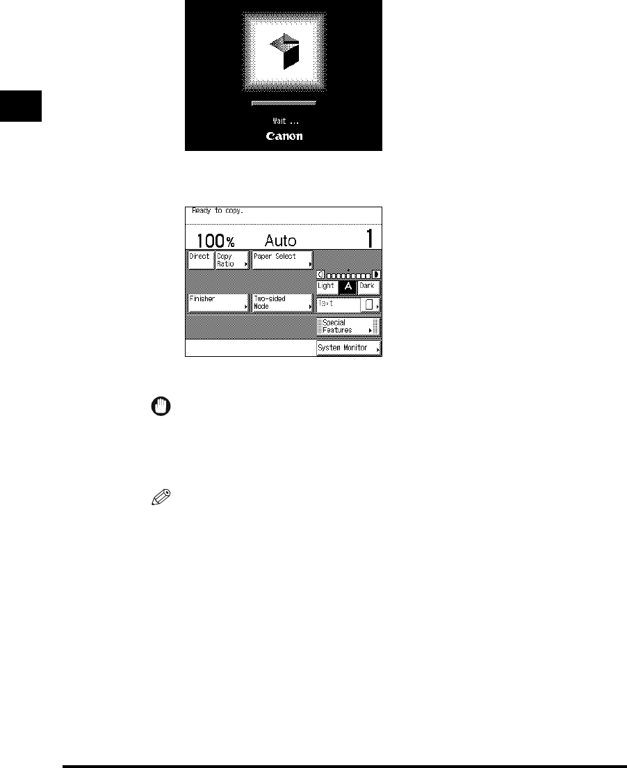
1
Main Power and Control Panel Power
1-24
Before You Start Using This Machine
The screen below is displayed until the machine is ready to scan.
The screen below is displayed when the machine is ready to scan.
The machine is ready to print after about 29 seconds (at a room temperature of 68°F).
IMPORTANT
•
If you turn off the main power, wait at least three seconds before turning the main power back
on.
•
Do not turn the power off if the FAX Board is attached. Transmission/Receive of fax cannot be
done when the power is turned off.
NOTE
•
In the case above, the Standard settings are selected.
•
The standard copy settings are as follows:
- Copy ratio: Direct (100%)
-Paper selection: Auto Paper Selection
- Copy exposure: Auto Exposure Control
- Copy quantity: 1
- Copy function: 1→1-sided copy
•
You can change the standard copy settings. (See the Copying Guide.)
•
You can choose which functions to display in the Basic Features screen when turning on the
main power according to the Additional Functions settings. (See ‘Selecting the Initial Function
at Power ON,’ on p. 3-8.)
E1L_US_U_.book-INDEX Page 24 Wednesday, May 23, 2001 11:40 PM
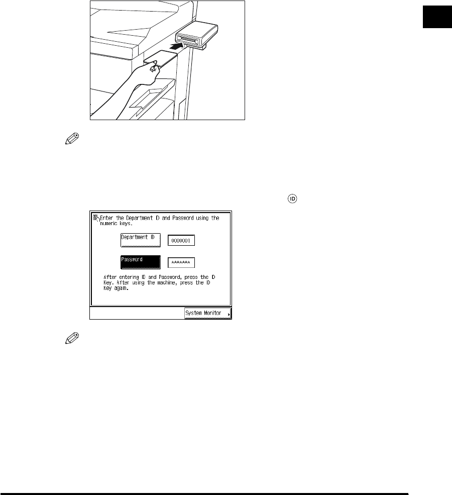
1
Main Power and Control Panel Power 1-25
Before You Start Using This Machine
3
When a message appears on the touch panel display, follow the
instructions.
●If the message <You must insert a control card.> appears:
Insert a control card.
NOTE
•
See ‘Card Reader-C1,’ on p. 7-80.
●If the message <Enter the Department ID and Password using the numeric
keys.> appears:
Enter the Department ID and Password, and press (ID).
NOTE
•
See ‘Operations After Turning the Power On,’ on p. 1-36, for how to enter the department ID
and Password.
E1L_US_U_.book-INDEX Page 25 Wednesday, May 23, 2001 11:40 PM

1
Main Power and Control Panel Power
1-26
Before You Start Using This Machine
Control Panel Power Switch
Press the control panel power switch to cancel the Sleep mode and resume normal machine
operations.
NOTE
•
The machine can receive and print documents from a personal computer even when it is in the
Sleep mode. Faxes can also be received during the Sleep mode.
•
It takes about 10 seconds for the machine to be ready for copying/printing, after the Sleep mode is
canceled.
E1L_US_U_.book-INDEX Page 26 Wednesday, May 23, 2001 11:40 PM

The System Settings of This Machine 1-27
Before You Start Using This Machine
1
The System Settings of This Machine
It is necessary to set up the machine before using it on a network or with the printer, and fax
function.
Refer to the following instructions:
■Setting up and Connecting to the Network
See the Network Guide.
■Installing the Printer Driver
See the PS/PCL Driver Guide.
■Date and Time Settings
See ‘Setting the Current Date and Time,’ on p. 3-30
■Entering System Manager Settings
See ‘Setting Specifications of System Manager Settings (System Manager Settings),’ on
p. 4-2.
E1L_US_U_.book-INDEX Page 27 Wednesday, May 23, 2001 11:40 PM
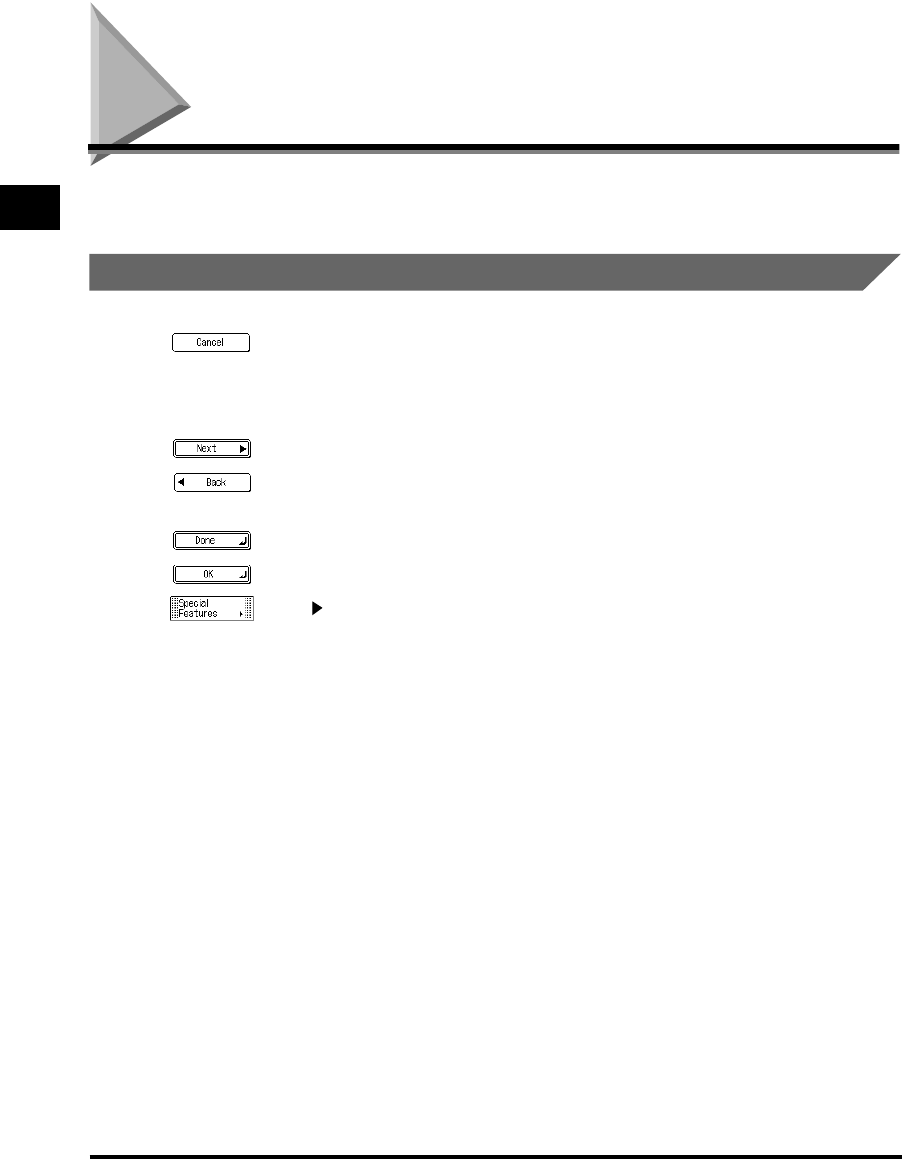
Using the Touch Panel Display
1-28
Before You Start Using This Machine
1
Using the Touch Panel Display
This section describes the keys that are frequently used on the touch panel display and how
they are displayed.
Frequently-used Keys on the Touch Panel Display
The following keys on the touch panel display are used frequently.
Press to close the current setting screen, retaining the programmed settings in
the Additional Functions screen.
Press to cancel the function (mode) that is either being set, or has already been
set, in screens other than the Additional Functions screen.
Press to set the function (mode) and proceed to the next setting procedure.
Press to go back to the previous procedure, saving the setting already made,
when setting a function (mode).
Press to close the present screen.
Press to decide the setting of a function (mode).
The < > mark in some keys indicates that those keys have another screen to
set their functions.
E1L_US_U_.book-INDEX Page 28 Wednesday, May 23, 2001 11:40 PM

1
Using the Touch Panel Display 1-29
Before You Start Using This Machine
Touch Panel Key Display
When you press a key displayed on the screen, that key is highlighted and the corresponding
function (mode) is set. When you set certain functions (modes), the characters on some keys
may become difficult to see, that is, the image becomes paled. You cannot press the keys
with a paled image, which means that you cannot set these functions in combination with the
presently set function (mode).
A tick ( ) appears on the screen for some keys when you press the keys.
CAUTION
•Press the touch panel keys gently with a finger. Do not press the touch panel with a
pencil, ballpoint pen, or other sharp objects that can scratch the surface of the touch
panel or break it.
NOTE
•
Before using the touch panel display, peel off the protective film from the display.
Functions that can be set in
combination with the
presently set function
Functions that cannot be set
in combination with the
presently set function
Presently set function
Presently set function
E1L_US_U_.book-INDEX Page 29 Wednesday, May 23, 2001 11:40 PM
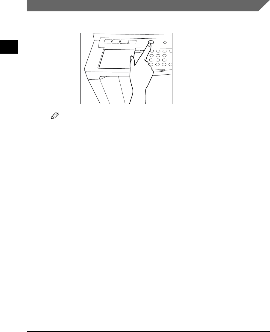
1
Using the Touch Panel Display
1-30
Before You Start Using This Machine
Adjusting the Brightness of the Touch Panel Display
If the touch panel display is difficult to view, use the display contrast dial on the control panel
to adjust its brightness.
NOTE
•
To make the touch panel brighter, turn the dial counterclockwise. To make it darker, turn the dial
clockwise.
E1L_US_U_.book-INDEX Page 30 Wednesday, May 23, 2001 11:40 PM
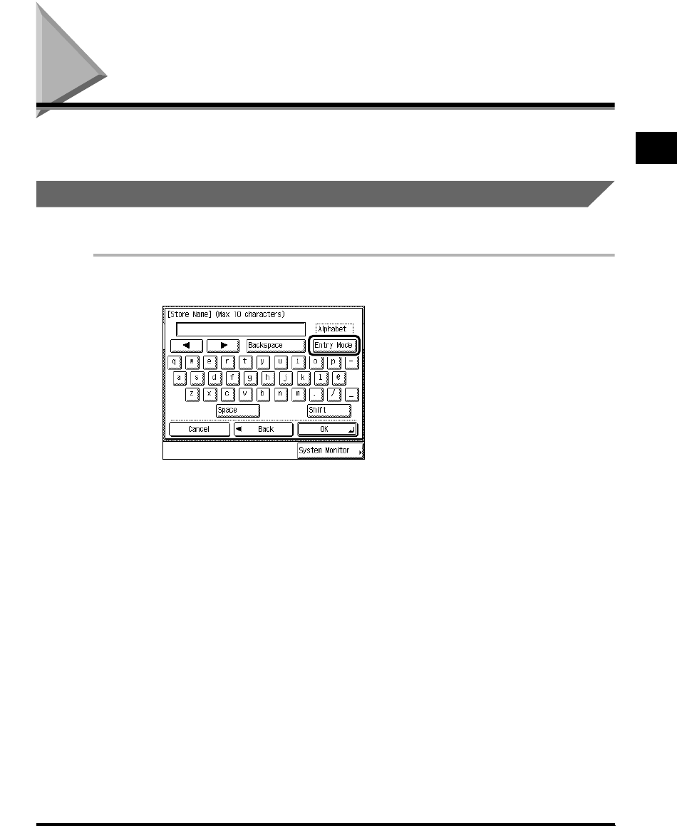
Entering Characters from the Touch Panel Display 1-31
Before You Start Using This Machine
1
Entering Characters from the Touch Panel Display
In screens which require alphanumeric entry, enter characters using the alphabet keys
displayed in the touch panel display, as described below.
Entering Alphabet Characters
Example: Enter <Canon>.
1
Press “Entry Mode” to select “Alphabet.”
Each press of “Entry Mode” switches the entry mode between “Alphabet” and “Other.”
If you press “Shift,” the entry mode changes to upper case mode, in which upper case
characters, comma, and colon can be entered.
E1L_US_U_.book-INDEX Page 31 Wednesday, May 23, 2001 11:40 PM

1
Entering Characters from the Touch Panel Display
1-32
Before You Start Using This Machine
2
Enter <Canon>.
<Canon> is displayed.
To enter a space, press “Space.”
To move the cursor, press “ ” or “ .”
To enter special characters, press “Entry Mode” before you press “OK” to select “Other.”
NOTE
•
If you make a mistake when entering characters, use “ ” or “ ” to position the cursor, and
“Backspace” to delete the character. Then, enter the correct character.
•
You can also delete all characters you have entered by pressing (Clear).
•
The available modes and maximum number of letters vary depending on the entry field.
3
When you have entered all characters, press “OK.”
E1L_US_U_.book-INDEX Page 32 Wednesday, May 23, 2001 11:40 PM

1
Entering Characters from the Touch Panel Display 1-33
Before You Start Using This Machine
Entering Special Characters
Example: Enter <#>.
1
Press “Entry Mode” to select “Other.”
Each press of “Entry Mode” switches the entry mode between “Alphabet” and “Other.”
2
Press “▼” or “▲” to display the desired special character.
3
Press “#.”
“#” is displayed.
E1L_US_U_.book-INDEX Page 33 Wednesday, May 23, 2001 11:40 PM

1
Entering Characters from the Touch Panel Display
1-34
Before You Start Using This Machine
To enter a space, press “Space.”
To move the cursor, press “ ” or “ .”
To enter alphabet characters, press “Entry Mode” before you press “OK” to select
“Alphabet.”
NOTE
•
If you make a mistake when entering special letters, use “ ” or “ ” to position the cursor,
and “Backspace” to delete the character. Then, enter the correct character.
•
You can also delete all characters you have entered by pressing (Clear).
•
The available modes and maximum number of letters vary depending on the entry field.
4
When you have finished entering the special characters, press “OK.”
E1L_US_U_.book-INDEX Page 34 Wednesday, May 23, 2001 11:40 PM

1
Entering Characters from the Touch Panel Display 1-35
Before You Start Using This Machine
Entering in Inches
When you want to enter values in inches in all modes which require numeric entry, set the
inch entry function to “On” from the Common Settings of the Additional Functions screen.
(See ‘Setting Inch Input,’ on 3-12.) You can then enter inches once you press “Inch” in a
screen requiring numeric entry.
The following example (1-1/2") shows inch entry in the Zoom Program mode.
1
To enter 1-1/2 inches, press “1,” “_,” “1,” “/,” and “2” in the screen,
in this order.
The entered values are displayed as shown above.
E1L_US_U_.book-INDEX Page 35 Wednesday, May 23, 2001 11:40 PM
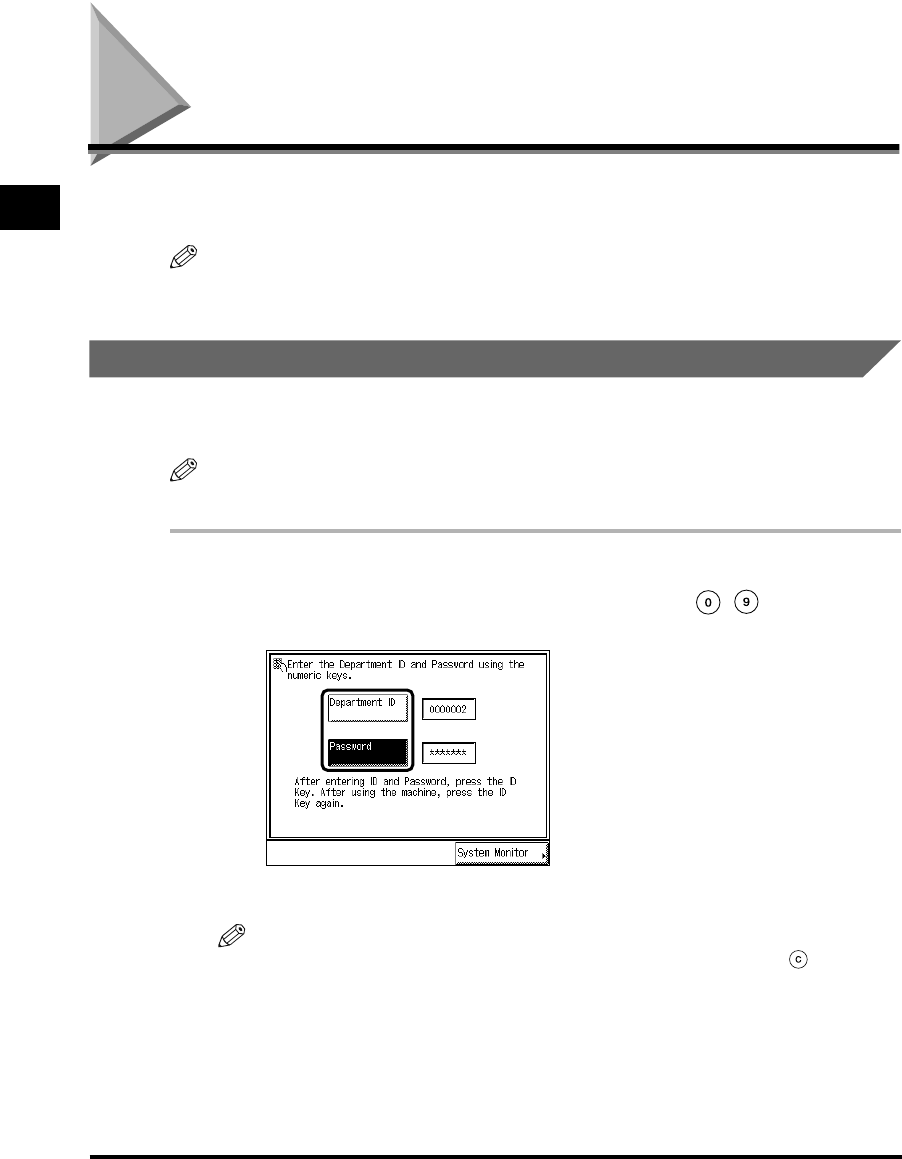
Entering the Department ID and Password
1-36
Before You Start Using This Machine
1
Entering the Department ID and Password
When Department ID Management has been set, the Department ID and Password must be
entered before operating this machine.
NOTE
•
When you are using the control card, the message <You must insert a control card.> appears in the
touch panel display. Insert the control card into the card slot. (See ‘Card Reader-C1,’ on p. 7-82.)
Operations After Turning the Power On
After turning the power on and the machine becomes ready to scan, the screen for entering
the Department ID and Password appears.
NOTE
•
For details of how to turn the power on, see ‘Main Power and Control Panel Power,’ on p. 1-23.
1
Press “Department ID” and enter the department ID, then press
“Password” and enter the password, using the - (numeric
keys).
If the Password is not set, proceed to step 2.
NOTE
•
If you made a mistake when entering the Department ID or Password, press (Clear), and
enter the correct value.
E1L_US_U_.book-INDEX Page 36 Wednesday, May 23, 2001 11:40 PM
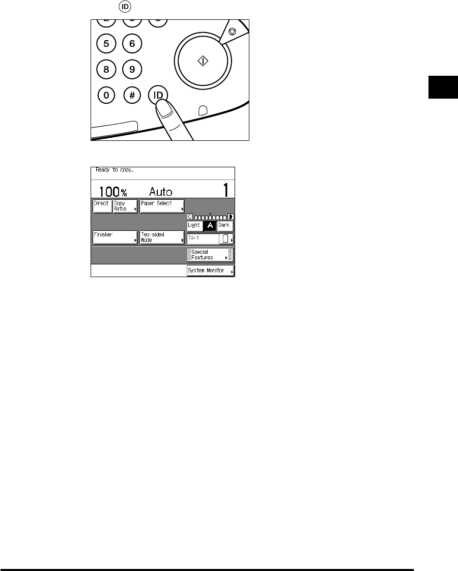
1
Entering the Department ID and Password 1-37
Before You Start Using This Machine
2
Press (ID).
The Basic Features screen of the selected function appears on the touch panel display.
If the Department ID and/or Password that you entered are wrong, the message <This
number has not been stored. Enter the number again.> appears. Repeat the procedure
from step 1.
JKL
TUV
MNO
WXY
O
PER
Start
Power
Error
g/Data
Stop
E1L_US_U_.book-INDEX Page 37 Wednesday, May 23, 2001 11:40 PM

1
Entering the Department ID and Password
1-38
Before You Start Using This Machine
Operations After Using Copy Functions
1
When your copy operations are completed, press (ID) on the
control panel.
The screen for entering the Department ID and Password appears.
NOTE
•
To perform copy operations again, enter the Department ID and Password.
•
If you do not press (ID) after finishing your copy operations, any subsequent copies will be
totaled under the Department ID which you previously entered.
•
When copy operations have been completed, the screen for entering the Department ID and
Password automatically appears, after the set time has elapsed, even if you forget to press
(ID). (See ‘Setting the Time Taken for the Display to Return to the Basic Features Screen
After Finishing Operations,’ on p. 3-34.)
JKL
TUV
MNO
WXY
O
PER
Start
Power
Error
g/Data
Stop
E1L_US_U_.book-INDEX Page 38 Wednesday, May 23, 2001 11:40 PM

Placing Originals 1-39
Before You Start Using This Machine
1
Placing Originals
Set the originals on the platen glass or in the feeder, depending on the size and type that you
want to print and the settings that you have programmed.
NOTE
•If the original has too many pages to be placed in the feeder all at once during basic Copy/Mail
Box operations, use the Job Build mode. (See the Copying Guide and the Mail Box Function
Guide.)
■Platen glass
Place the originals on the platen glass when scanning bound originals, originals on heavy
or lightweight paper, and transparencies.
■Feeder
Place a stack of originals in the feeder, and press (Start). The machine automatically
scans them into memory. Two-sided originals can also be automatically turned over and
scanned as two-sided image data.
E1L_US_U_.book-INDEX Page 39 Wednesday, May 23, 2001 11:40 PM
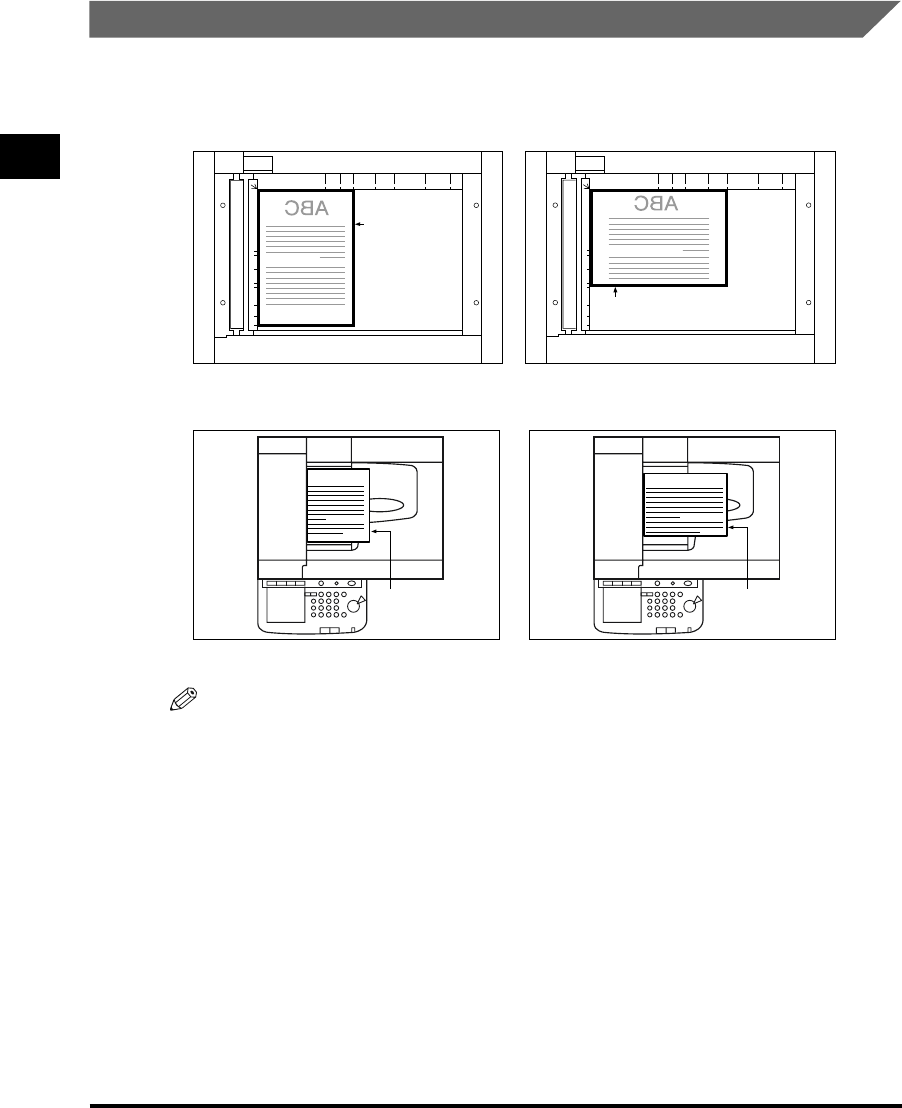
1
Placing Originals
1-40
Before You Start Using This Machine
Orientation of Originals
You can place original either vertically or horizontally. Always align the top edge of your
original with the back edge of the platen glass (top left corner) or the feeder.
NOTE
•If the top edge of the original is not aligned with the back edge of the platen glass, prints may not
be made correctly, depending on the mode you have set.
•
LTR and STMT-size originals can be placed either vertically or horizontally. However, the scanning
speed for horizontally placed originals is somewhat slower than for vertically placed originals. You
can place originals horizontally when printing with Preset Zoom mode, such as when processing
LTR
→
11" x 17".
•
Horizontally placed LTR and STMT-size originals are referred to as LTRR and STMTR.
•
11" x 17" and LGL-size originals must be placed horizontally.
Place the original
face down
Place the original
face down
ABC ABC
Place the original
face up Place the original
face up
[Platen glass]
[Feeder]
Horizontal placementVertical placement
Horizontal placementVertical placement
E1L_US_U_.book-INDEX Page 40 Wednesday, May 23, 2001 11:40 PM

1
Placing Originals 1-41
Before You Start Using This Machine
Placing an Original on the Platen Glass
You should use the platen glass when scanning books and other bound originals, heavy or
lightweight paper originals, transparencies, etc., into memory.
NOTE
•
The machine automatically detects the size of following originals: 11" x 17", LGL, LTR, LTRR, and
STMTR.
1
Lift up the feeder/platen glass cover.
IMPORTANT
•This machine is equipped with an open/close sensor of the feeder/platen glass cover.
When placing originals on the platen glass, lift the feeder/platen glass cover about 11-7/8"
(30cm). If the sensor does not detach from the feeder, the size of originals may not be
detected correctly.
2
Place your original.
E1L_US_U_.book-INDEX Page 41 Wednesday, May 23, 2001 11:40 PM
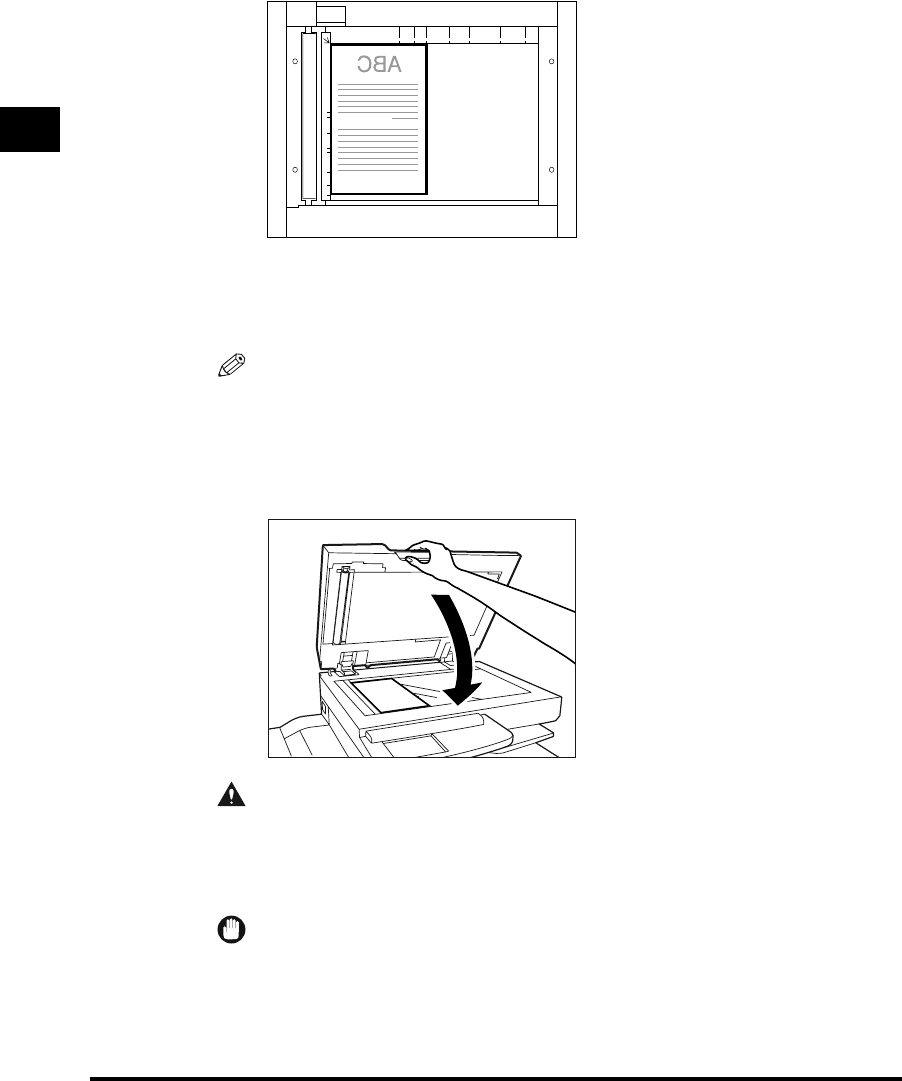
1
Placing Originals
1-42
Before You Start Using This Machine
The surface that you want to scan into memory must be placed face down. Align the corner
of the original with the top left corner (the arrow) of the platen glass.
Place books and other bound originals on the platen glass in the same way.
When enlarging LTR or STMT-size originals to 11" x 17" or LGL-size paper, place the
original horizontally on the platen glass, and align it with the LTRR or STMTR marks.
NOTE
•
When copying STMT-size originals using the platen glass, you need to set “LTRR/STMT
Original Selection” in Additional Functions. (See ‘Distinguishing LTRR-size and STMT-size
Originals,’ on p. 3-19.)
3
Gently lower the feeder/platen glass cover.
CAUTION
•Close the feeder/platen glass cover gently, to avoid catching your hand, as this may
result in personal injury.
•Do not press down the feeder/platen glass cover with force when scanning thick
books. This may damage the platen glass and cause personal injury.
IMPORTANT
•When placing originals on the platen glass, the size of the original is detected after the
feeder/platen glass cover has been lowered. Be sure to lower the feeder/platen glass cover
before copying.
E1L_US_U_.book-INDEX Page 42 Wednesday, May 23, 2001 11:40 PM
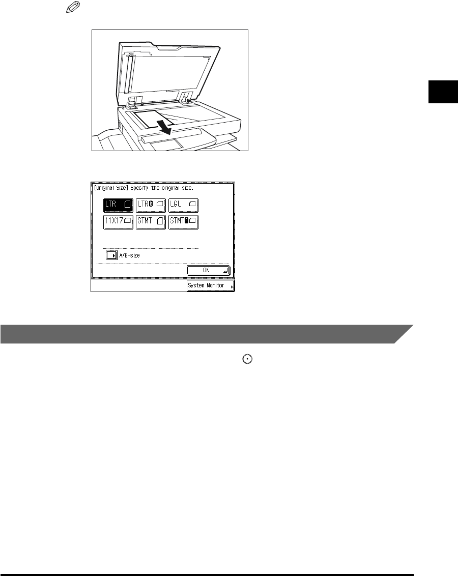
1
Placing Originals 1-43
Before You Start Using This Machine
NOTE
•Remove the original from the platen glass when scanning is completed.
•
STMT size and postcards cannot be detected. Follow the instructions on the display and
specify the original size or select the paper.
Placing Originals in the Feeder (DADF-H1)
Place a stack of originals in the feeder, and press (Start). The machine automatically
scans them into memory. Two-sided originals can also be automatically scanned as two-
sided image data.
You can place the following originals in the original supply tray:
•Weight: One-sided scanning:10 to 32-lb bond (38 to 128g/m2)
(However, the sizes marked* below is 11 to 32-lb bond (42 to 128g/m2))
Two-sided scanning:13 to 32-lb bond (50 to 128g/m2)
• Size: 11" x 17"*, LGL*, LTR, LTRR*, STMT, and STMTR
•Tray capacity: 50 sheets (20-lb bond (80g/m2))
10 sheets (11-lb bond (40g/m2) or less)
E1L_US_U_.book-INDEX Page 43 Wednesday, May 23, 2001 11:40 PM

1
Placing Originals
1-44
Before You Start Using This Machine
IMPORTANT
•
Originals of 11-lb bond (40g
/m2
) or less may become creased, if used in a high temperature or high
humidity environment.
•
Do not place the following types of originals in the feeder:
-Originals with tears or large binding holes
-Severely curled originals or originals with sharp folds
- Clipped or stapled originals
- Carbon-backed paper or other originals which might not feed smoothly
-Transparencies and other highly transparent originals
•
If the feeder rollers are soiled from scanning an original written with pencil, perform the Feeder
Cleaning procedure. (See ‘Cleaning the Feeder
1
,’ on p. 5-17, and ‘Cleaning the Feeder
2
,’ on p.
5-20.)
1
Adjust the slide guides to fit the size of the originals.
2
Neatly place your originals face up in the original supply tray.
When enlarging LTR or STMT-size originals to 11" x 17" or LGL-size paper, place your
originals horizontally.
Place the original as far as it will go, until the original set indicator is lit.
E1L_US_U_.book-INDEX Page 44 Wednesday, May 23, 2001 11:40 PM

1
Placing Originals 1-45
Before You Start Using This Machine
IMPORTANT
•Do not add or remove originals while they are being scanned.
•
When scanning is completed, remove the originals from the original output area to avoid
paper jams.
NOTE
•The scanned originals are output face down to the original output area.
•
You can place different-size originals (i.e., LTR and 11" x 17", STMT and LTRR) together in
one group in the feeder when you set the Different Size Originals mode. (See the Copying
Guide and the Mail Box Function Guide.)
Original output area
E1L_US_U_.book-INDEX Page 45 Wednesday, May 23, 2001 11:40 PM

Making Prints Using the Stack Bypass
1-46
Before You Start Using This Machine
1
Making Prints Using the Stack Bypass
When making prints on transparencies, or non-standard size paper stock, load the paper
stock in the stack bypass.
IMPORTANT
•
Note the following points when using the stack bypass:
- Copy quantity: 1 to about 50 sheets (stack about 1/4" (5mm) high)
-Paper size: 4" x 5-1/2" to 11-3/4" x 17" (100mm x 139mm to 297mm x 432mm)
-Paper weight: 17-lb bond to 32-lb (64g/m2 to 128g/m2)
- Curl down paper before use. (Curl amount: less than 3/8" (10mm) for normal paper; less than
1/4" (5 mm) for heavy paper.) There are some types of paper stock which may meet the above
specifications but cannot be fed in the stack bypass.
•
Do not load different size/type paper at the same time.
•
LTR-size tracing paper must be placed vertically in the stack bypass. Placing this paper horizontally
may cause creases on the print, depending on the moisture absorption condition of the paper.
•
LTR-size transparencies must be placed vertically in the stack bypass. Placing this paper
horizontally may cause blurred images.
•
When making two-sided prints, select the Two-sided mode. Not selecting the correct mode may,
cause creases on the print, depending on the moisture absorption condition of the paper.
•
To print on the rear side of printed paper, it is recommended you load the paper in one of the paper
drawers.
•
When printing on envelopes, empty the output tray when at most 10 printed envelopes accumulate in
the tray.
•
When you select “Free Size” for copying, you cannot use the Auto Zoom, Entire Image, Finisher,
Hole Punch, 1 2-Sided, 2 2-Sided, Book 2-Sided, Two-page Separation, Cover/Sheet
Insertion, Shift (Center/Corner), Booklet, Transparency Interleaving, Image Combination, Image
Separation, or Image Repeat modes.
•
When you select “Free Size” for printing documents stored in the mail box, you cannot use the
Finisher, 2-Sided, Document Contiguous/Separate Duplex Printing, Cover/Sheet Insertion, or
Booklet modes.
NOTE
•When scanning the following originals, you cannot use Automatic Paper Selection. Use Manual
Paper Selection with these types.
- Highly transparent originals such as transparencies
-Originals with an extremely dark background
■Standard Size
You can select standard inch paper, or A or B series paper.
E1L_US_U_.book-INDEX Page 46 Wednesday, May 23, 2001 11:40 PM
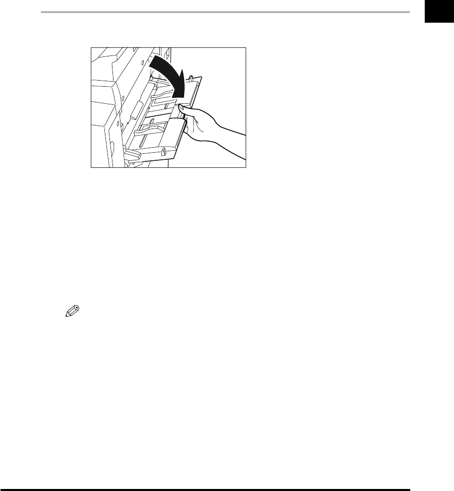
1
Making Prints Using the Stack Bypass 1-47
Before You Start Using This Machine
■Free Size
You can place non-standard size paper (4" x 5-1/2" to 11-3/4" x 17" (100mm x 139mm to
297mm x 432mm)).
■Envelope
The following envelopes can be loaded into the envelope cassette: COM10, ISO-B5,
Monarch, ISO-C5, DL, and Yougata 4.
1
Open the stack bypass.
●If the specified paper has already been loaded in the Stack Bypass:
Press “Paper Select,” and select the desired paper.
●If paper different from that specified is loaded in the Stack Bypass:
Check to see if any job is reserved. (See ‘Flow of Checking/Changing Operations,’
on p. 2-2.)
If there is a current/reserved job, reserve a change for the stack bypass. (See ‘Using the
Stack Bypass While Reserving Print Jobs,’ on p. 1-54.)
When there is no reserved job, continue the procedure from step 2.
NOTE
•
If the paper size loaded in the stack bypass is different from the paper size stored in Standard
Stack Bypass Settings, press “Stack Bypass Settings” and change the setting to the loaded
paper size. (See ‘Setting the Standard Paper for the Stack Bypass,’ on p. 3-24.)
E1L_US_U_.book-INDEX Page 47 Wednesday, May 23, 2001 11:40 PM
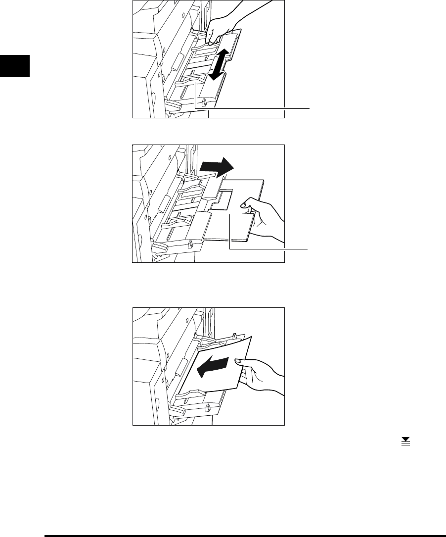
1
Making Prints Using the Stack Bypass
1-48
Before You Start Using This Machine
2
Adjust the slide guides to the size of the paper.
When feeding large-size paper, pull out the auxiliary tray.
3
Load the paper in the stack bypass.
Make sure that the height of the paper stack does not exceed the limit mark ( ).
Align the required number of sheets of paper with the slide guides. The surface that you
want to print on (opened surface) must be placed face up. Insert the paper into the
machine until it stops.
Slide Guide
Auxiliary tray
E1L_US_U_.book-INDEX Page 48 Wednesday, May 23, 2001 11:40 PM

1
Making Prints Using the Stack Bypass 1-49
Before You Start Using This Machine
●Loading envelopes in the stack bypass.
Take five or so envelopes, and loosen them as shown, then stack them together.
Repeat this step 5 times.
Place the envelopes on a clean, level surface and spread them out by hand in the
direction of the arrows.
Repeat this step 5 times.
IMPORTANT
•
Take particular care to spread the envelopes out in the direction they will be fed.
E1L_US_U_.book-INDEX Page 49 Wednesday, May 23, 2001 11:40 PM
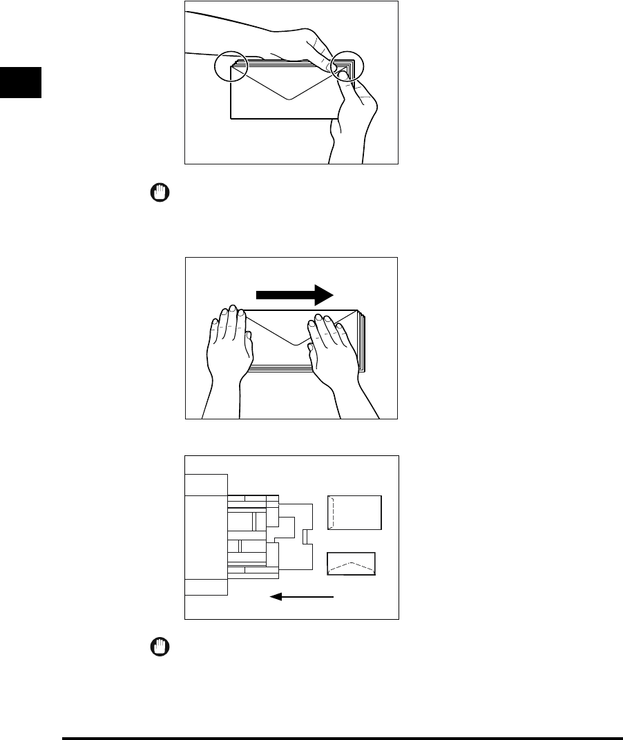
1
Making Prints Using the Stack Bypass
1-50
Before You Start Using This Machine
Hold down the four corners of the envelopes firmly, so that they and the sealed or
glued portion stay flat.
IMPORTANT
•
Do not print on the underside of the envelopes.
•
If the envelopes become filed with air, flatten them by hand before loading them in the
envelope feeder attachment.
Load the envelopes as shown below.
IMPORTANT
•
When printing data from a personal computer, always load the envelopes as shown above.
Feeding
Direction
E1L_US_U_.book-INDEX Page 50 Wednesday, May 23, 2001 11:40 PM
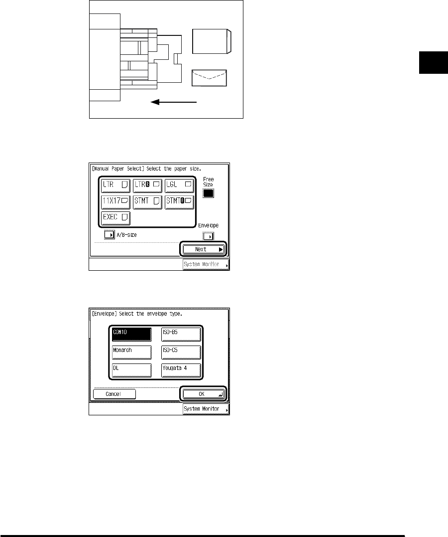
1
Making Prints Using the Stack Bypass 1-51
Before You Start Using This Machine
When Saddle Finisher-G1 is attached, and Image Orientation Priority is set to
“On,” load the envelopes as shown below.
4
Select the paper size, and press “Next.”
If envelopes are loaded, press “Envelope,” and specify the envelope type. Then press
“OK” → “OK,” and proceed to step 6.
When loading paper other than a standard size, press “Free Size.”
To select A or B series paper size, press “A/B-size.”
Feeding
Direction
E1L_US_U_.book-INDEX Page 51 Wednesday, May 23, 2001 11:40 PM

1
Making Prints Using the Stack Bypass
1-52
Before You Start Using This Machine
If the following screen is displayed, adjust the width of the slide guide and set the size.
IMPORTANT
•Set the paper size to the same size as the paper loaded in the stack bypass.
•
Designate which envelope type you want to set. If the envelope type is not designated
correctly, a paper jam will occur.
5
Select the type of paper (Plain, Heavy, etc.), and press “OK.”
IMPORTANT
•Select the correct paper type to avoid a paper jam.
NOTE
•For details of paper types, see ‘Available Paper Stock,’ on p. 1-57.
E1L_US_U_.book-INDEX Page 52 Wednesday, May 23, 2001 11:40 PM

1
Making Prints Using the Stack Bypass 1-53
Before You Start Using This Machine
6
Press “Done.”
When you press “Stack Bypass Setting,” you can set the paper size again.
7
Place your originals, and program the copy settings.
When printing documents stored in a mail box, this procedure is not necessary.
NOTE
•When there is no reserved job, continue the procedure from step 2.
8
Press (Start).
When printing documents stored in a mail box, press “Start Print.”
Copying starts.
NOTE
•If heavyweight paper or envelopes are not fed normally from the stack bypass when
printing, curl up the edge of the paper by about 1/8" (3 mm) before loading it.
•
To cancel all settings and return the machine to the standard mode, press (Reset).
Paper size loaded presently
Paper size selected
E1L_US_U_.book-INDEX Page 53 Wednesday, May 23, 2001 11:40 PM
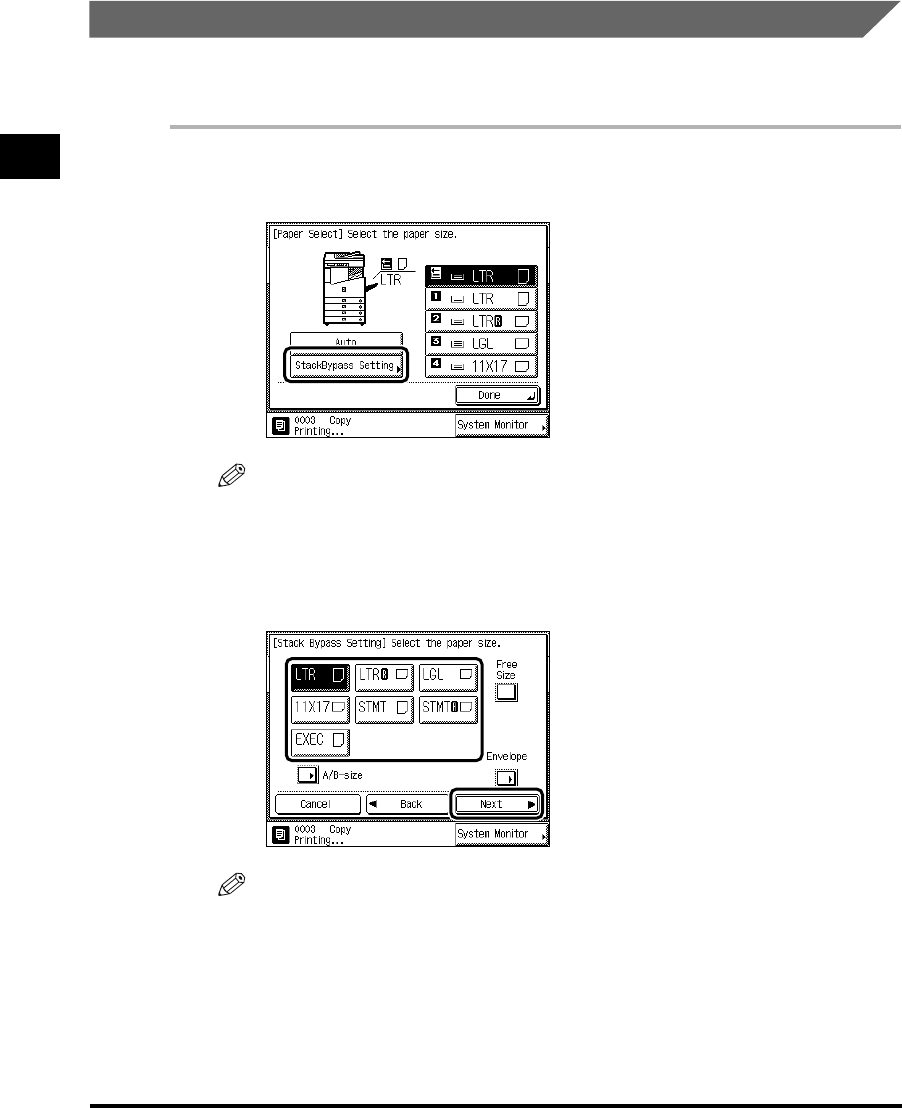
1
Making Prints Using the Stack Bypass
1-54
Before You Start Using This Machine
Using the Stack Bypass While Reserving Print Jobs
When paper is being fed from the stack bypass for the current print job, or a job is reserved,
you can designate the paper to be loaded in the stack bypass for the next reserved job.
1
Press “Stack Bypass Setting” in the Paper Selection screen that
appears when specifying reserved print settings.
NOTE
•
When Standard Stack Bypass Settings is set to “On,” and “Stack Bypass” is selected, the
paper stored in the Standard Settings is displayed. (See ‘Setting the Standard Paper for the
Stack Bypass,’ on p. 3-24.)
2
Select the paper size, and press “Next.”
NOTE
•To select free size paper, press “Free Size.”
•
To select envelopes, press “Envelope.”
•
To select A or B series paper size, press “A/B-size.”
•
When storing paper as Standard Stack Bypass Settings, the paper size/type are displayed.
(See ‘Setting the Standard Paper for the Stack Bypass,’ on p. 3-24.)
E1L_US_U_.book-INDEX Page 54 Wednesday, May 23, 2001 11:40 PM

1
Making Prints Using the Stack Bypass 1-55
Before You Start Using This Machine
3
Select the paper type, and press “OK.”
The paper currently loaded and the paper reserved to be loaded are displayed, as shown in
the following screen.
4
Press “Done.”
This completes the reserved specifications for the originals you plan to set in the feeder.
5
Press (Start).
When printing documents stored in a mail box, press “Start Print.”
6
Load the specified paper when its turn comes to print.
Paper size loaded presently
Paper size selected
E1L_US_U_.book-INDEX Page 55 Wednesday, May 23, 2001 11:40 PM
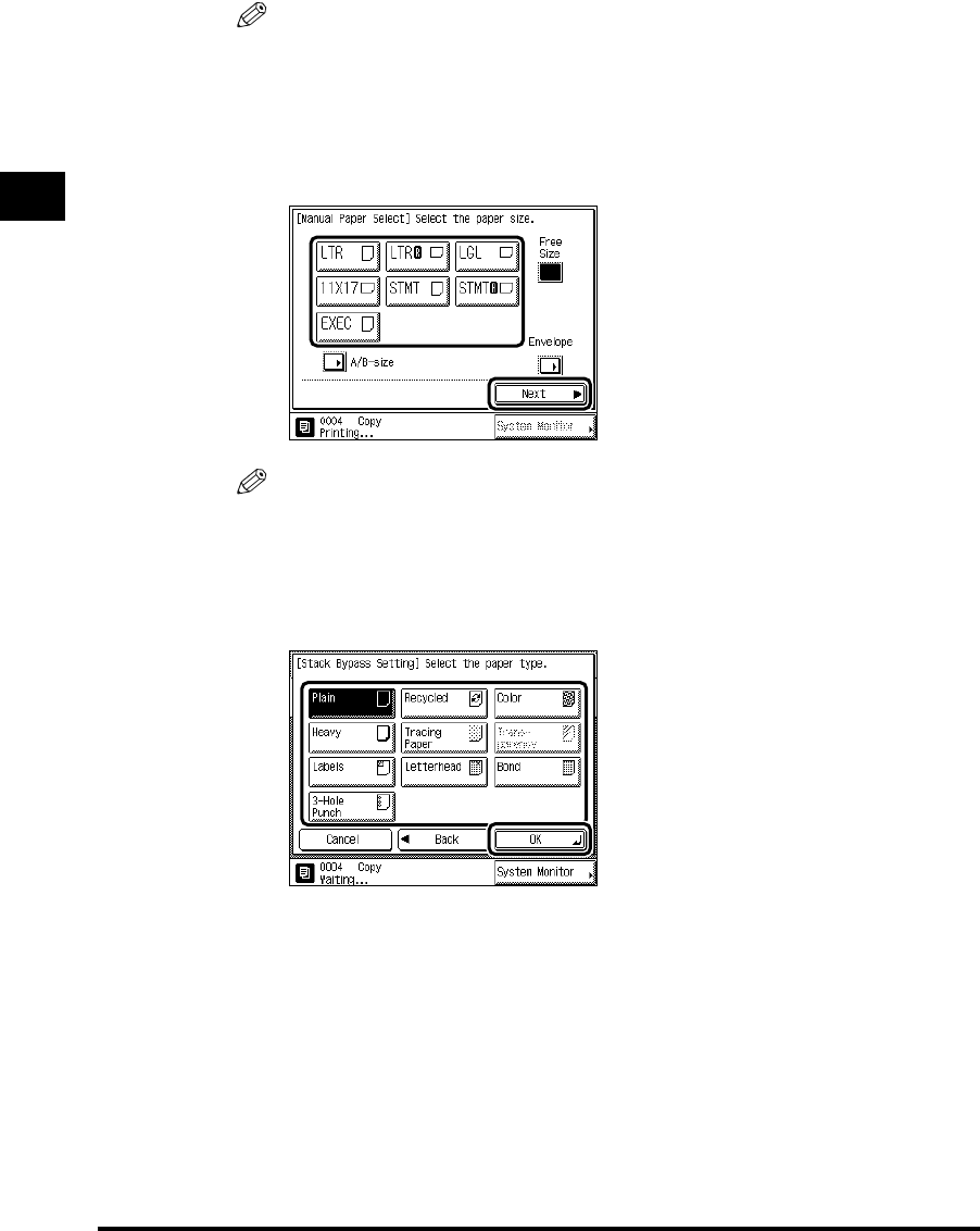
1
Making Prints Using the Stack Bypass
1-56
Before You Start Using This Machine
NOTE
•
The specified paper size is displayed when its turn comes to print.
•
Even when setting reserved print settings, if paper is loaded in the stack bypass, specify the
same paper size and type as selected in steps 2 and 3. Otherwise, the machine does not start
printing.
7
Select the paper size, and press “Next.”
NOTE
•To select free size paper, press “Free Size.”
•
To select envelopes, press “Envelope.”
•
To select A or B series paper size, press “A/B-size.”
8
Select the paper type, and press “OK.”
The machine starts printing.
E1L_US_U_.book-INDEX Page 56 Wednesday, May 23, 2001 11:40 PM

Multi-function Operation 1-57
Before You Start Using This Machine
1
Multi-function Operation
The imageRUNNER 3300/2800/2200 is a multi-function machine equipped with such
capabilities as Print and Fax, in addition to the Copy function. You can operate these
functions together (Multi-function Operation). The following table presents details of multi-
function operations.
Copy Mail box
Scanning data Printing Scanning data Printing
Copy – –
Mail box Scanning data – –
Printing
Fax
TX (scanning included)
––
Memory TX
Memory RX
Printing of Auto RX
Documents
Printer Receiving data
Printing
Previous job
Next job
E1L_US_U_.book-INDEX Page 57 Wednesday, May 23, 2001 11:40 PM

1
Multi-function Operation
1-58
Before You Start Using This Machine
–: Unavailable due to the duplicate devices
: Operationally unavailable
: Available. Automatically resume the next job after performing the previous job.
: Available
‘TX (scanning included)’ includes a reservation of the direct sending.
FaxPrinter
Scanning
data TX RX Printing of
Auto RX
Documents Receiving
data Printing
Copy –
Mail box Scanning data –
Printing
Fax
TX (scanning included)
–
Memory TX
Memory RX ––
Printing of Auto RX
Documents
Printer Receiving data –
Printing
Next job
Previous job
E1L_US_U_.book-INDEX Page 58 Wednesday, May 23, 2001 11:40 PM

Available Paper Stock 1-59
Before You Start Using This Machine
1
Available Paper Stock
Paper types which can be used with this machine are shown in the following table. The type
of paper loaded in a paper drawer is indicated by the icon shown on the touch panel display
for that paper drawer. (See ‘Setting a Paper Drawer for Auto Paper Selection/Auto Drawer
Switching,’ on p. 3-13.)
*1 Plain, Recycled, Color, Bond, and 3-Hole Punch papers are from 17-lb to 20-lb bond (64g/m2 to 80g/m2).
*2 Heavy paper is from 24-lb bond to 72-lb index (81g/m2 to 128g/m2).
*3 Pre-printed paper with logos or patterns
*4 When copying on Letterhead or 3-Hole Punch paper, we recommend that you set the Image Orientation Priority to “On” in the
Additional Functions screen. (See the Copying Guide)
*5 Some types of tracing paper cannot be used.
*6 3-Hole Punch paper can only be set vertically (LTR). Set the 3-Hole Punch paper as follows according to its orientation:
Left open: when loading in the paper drawers, set the paper with the holes on the right side; when loading in the stack bypass,
set the paper with the holes on the left side.
Right open: reverse of left open orientation.
*7 When the Envelope Feeder Attachment-B1 (option) is attached to paper drawer 1, envelopes can be loaded.
Paper Type
Available Loading Place (Paper Set Place)
Paper drawer Stack bypass Paper Deck
Plain *1
Heavy *2 ––
Recycled *1
Color *1
Letterhead *3*4 ––
Tracing Paper *5 –
Transparency – –
Labels – –
3-Hole Punch *1*4*6
Bond *1 ––
Envelope *7 –
E1L_US_U_.book-INDEX Page 59 Wednesday, May 23, 2001 11:40 PM

1
Available Paper Stock
1-60
Before You Start Using This Machine
IMPORTANT
•
* When the Envelope Feeder Attachment-B1 (option) is attached to paper drawer 1, envelopes can
be loaded.
NOTE
•
For details of how to load paper, see the following pages:
-Paper drawer: ‘Loading Paper,’ on p. 5-2.
-Paper Deck: ‘Loading Paper in the Paper Deck,’ on p. 7-12.
-Stack bypass: ‘Making Prints Using the Stack Bypass,’ on p. 1-46.
•
Paper drawers 3, 4 and Paper Deck are optional.
Paper Size Length x Width
Available Loading Place (Paper Set Place)
Paper drawer 1, 3 Paper drawer 2, 4
Stack Bypass Paper Deck
11" x 17" 11" x 17" – –
LGL 8-1/2" x 14" –
LTR 11" x 8-1/2"
LTRR 8-1/2" x 11" –
STMT 8-1/2" x 5-1/2" –
STMTR 5-1/2" x 8-1/2" –
Envelope
*
ISO-B5
7" x 9-7/8"(176 x 250mm)
––
ISO-C5
6-3/8" x 9"(162 x 229mm)
––
COM 10
4-1/8" x 9-1/2"(104.7 x 241.3mm)
––
DL
4-3/8" x 8-5/8"(110 x 220mm)
––
Monarch
3-7/8" x 7-1/2"(98.4 x 190.5mm)
––
Yougata 4 4-1/8" x 9-1/4"(105 x 235mm)
––
Free Size
(4" x 5-7/8" to 11-3/4" x 17")
(100 x 148mm to 297 x 432mm)
– – –
E1L_US_U_.book-INDEX Page 60 Wednesday, May 23, 2001 11:40 PM

CHAPTER
2-1
2
Checking Job and
Device Status
Various methods of confirming and changing print jobs and additional, related functions are
explained in this chapter.
Flow of Checking/Changing Operations . . . . . . . . . . . . . . . . . . . . . . . . . . . . . . . . . . . . . .2-2
Checking/Canceling a Job in the Spooler . . . . . . . . . . . . . . . . . . . . . . . . . . . . . . . . . . . . . . . . . .2-4
Checking Print Job Details . . . . . . . . . . . . . . . . . . . . . . . . . . . . . . . . . . . . . . . . . . . . . . . .2-7
Canceling a Reserved Job . . . . . . . . . . . . . . . . . . . . . . . . . . . . . . . . . . . . . . . . . . . . . . . .2-8
Canceling from the Touch Panel Display . . . . . . . . . . . . . . . . . . . . . . . . . . . . . . . . . . . . . . . . . . .2-8
Canceling with (Stop) . . . . . . . . . . . . . . . . . . . . . . . . . . . . . . . . . . . . . . . . . . . . . . . . . . . . . . .2-9
Canceling from the System Monitor Screen . . . . . . . . . . . . . . . . . . . . . . . . . . . . . . . . . . . . . . . .2-10
Priority Printing. . . . . . . . . . . . . . . . . . . . . . . . . . . . . . . . . . . . . . . . . . . . . . . . . . . . . . . .2-12
Handling Print Jobs Sent from a Computer . . . . . . . . . . . . . . . . . . . . . . . . . . . . . . . . . .2-13
Printing Secured Documents . . . . . . . . . . . . . . . . . . . . . . . . . . . . . . . . . . . . . . . . . . . . .2-16
E1L_US_U_.book-INDEX Page 1 Wednesday, May 23, 2001 11:40 PM

Flow of Checking/Changing Operations
2-2
Checking Job and Device Status
2
Flow of Checking/Changing Operations
When you press “System Monitor,” the System Monitor screen appears allowing you to check
and change the status of Copy, Fax, and Print jobs. For example, you can change the order
of jobs in the print queue, cancel a job, check details of a job, or print a password-protected
job (secured print).
By displaying the Job List for each job type, it is possible to confirm the present job or a job
waiting to be processed, and by displaying the History List, it is possible to confirm a job
already processed. Also, it is possible to print a report of fax transmission/reception from the
System Monitor screen.
From the System Monitor screen, it is also possible to quickly acquire information about the
machine, check the amount of paper remaining in the paper drawers and optional drawers,
check the amount of memory currently being used, and view any error messages.
NOTE
•Many of the check/change operations can also be performed from the Remote UI. (See the
Remote UI Guide.)
1
Press “System Monitor.”
2
From the keys located at the top of the System Monitor screen,
select the Job Type (“Copy,” “Fax,” or “Print”) or press “Device” to
display the current machine status.
E1L_US_U_.book-INDEX Page 2 Wednesday, May 23, 2001 11:40 PM

2
Flow of Checking/Changing Operations 2-3
Checking Job and Device Status
●If Job Type is selected:
Press “Status.”
To see jobs currently being processed or waiting to be processed, press “Status.”
To see jobs that have already been processed, press “Log.”
NOTE
•
The status of each icon displayed in the screen is as follows:
-: Operating
-: Waiting
-: Error
-: Canceling
-: Paused
-: Secured job
-: Copy job
-: Mail Box job
-: Printer job
-: Fax job
-: Report job
•
The latest 128 copy or print jobs, or 40 fax jobs are displayed in the log.
E1L_US_U_.book-INDEX Page 3 Wednesday, May 23, 2001 11:40 PM
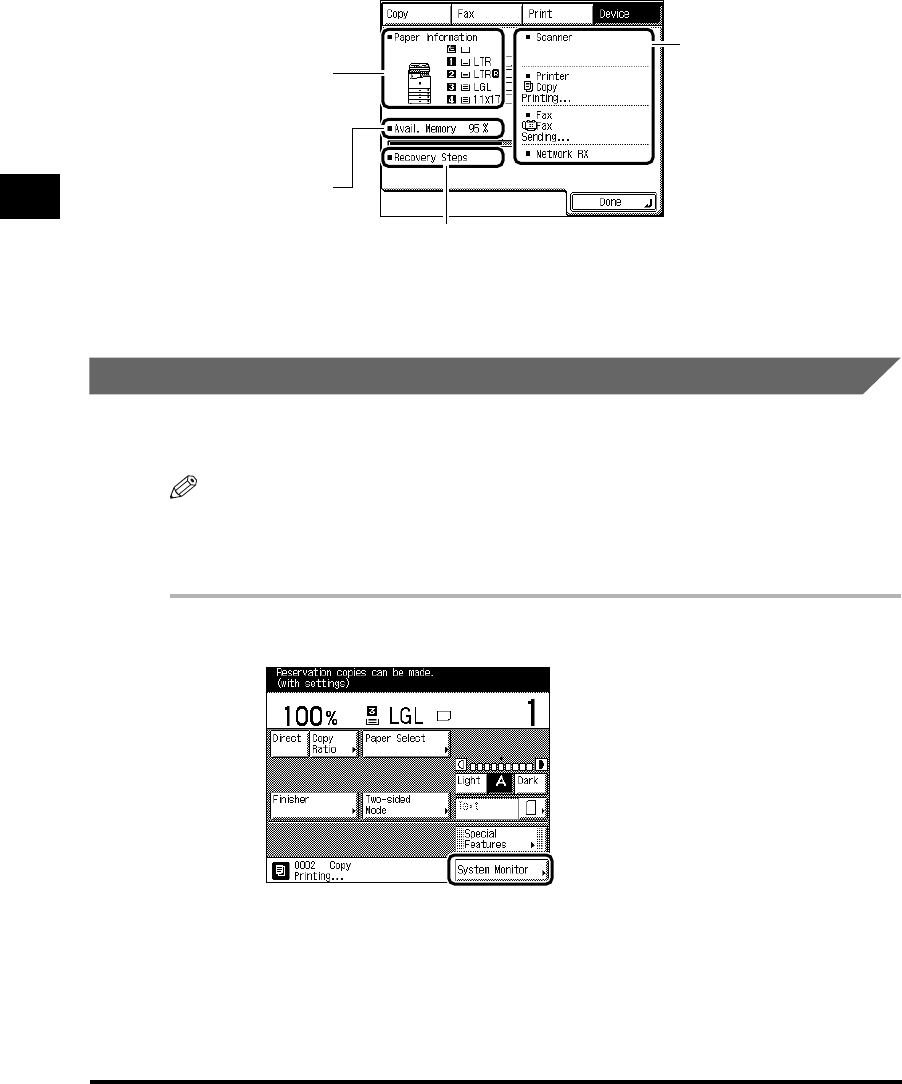
2
Flow of Checking/Changing Operations
2-4
Checking Job and Device Status
●If “Device” is selected:
Checking/Canceling a Job in the Spooler
When you send print data from a computer, it is stored in this machine as input. The machine
then processes this data and outputs it. This operation is called Spool.
NOTE
•“Spool Status” is displayed only when the Printer Kit is attached.
•
Operations such as checking or canceling spool jobs are possible only when Use Spooler is set to
“On.” For details, see the Network Guide.
1
Press “System Monitor.”
The status of the job
currently being
processed is
displayed.
The amount, type, and
size of paper loaded in
the paper drawers,
Cassette Feeding Unit-
W1 (option), and Paper
Deck L1 (option) are
displayed.
A key to show procedures for
removing paper jams, etc. is
displayed.
The amount of memory
available (%) is
displayed.
E1L_US_U_.book-INDEX Page 4 Wednesday, May 23, 2001 11:40 PM

2
Flow of Checking/Changing Operations 2-5
Checking Job and Device Status
2
Press “Print.”
3
Select “Spool Status.”
4
Press “ .”
E1L_US_U_.book-INDEX Page 5 Wednesday, May 23, 2001 11:40 PM
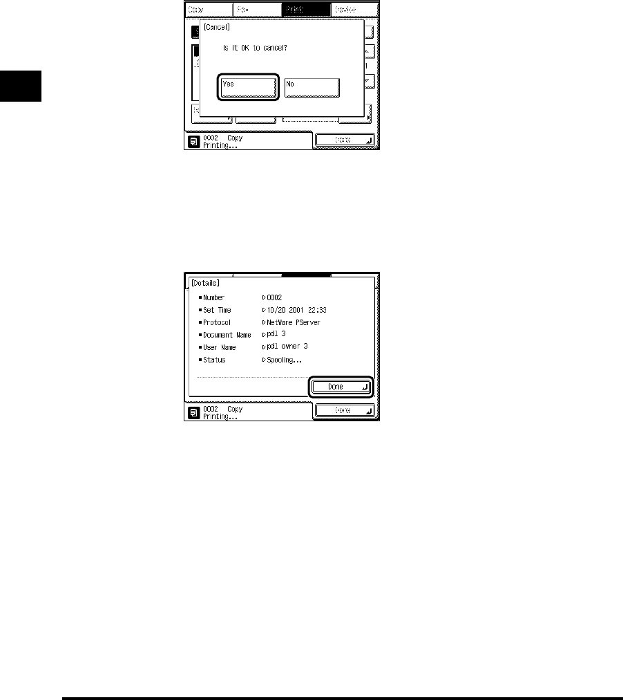
2
Flow of Checking/Changing Operations
2-6
Checking Job and Device Status
●To cancel a job in the spooler:
Select “Status.”
Select the job you want to cancel spooling, and press “Cancel.”
Press “Yes.”
If you do not want to cancel the job, press “No.”
●To check the job detailed information:
Select “Status” or “Log.”
Select the job you want to view more details about, and press “Details.” Check the
detailed information, and press “Done.”
5
Press “Done.”
The display returns to the Basic Features screen.
E1L_US_U_.book-INDEX Page 6 Wednesday, May 23, 2001 11:40 PM

Checking Print Job Details 2-7
Checking Job and Device Status
2
Checking Print Job Details
You can check job details, such as the date and time entered, and the number of pages.
1
Press “System Monitor,” and select the Job Type.
2
Press “Status” or “Log.” Select the job you want to view more details
about, and press “Details.”
3
Check the detailed information, and press “Done.”
Repeat this procedure as necessary.
The display returns to the Basic Features screen.
E1L_US_U_.book-INDEX Page 7 Wednesday, May 23, 2001 11:40 PM

Canceling a Reserved Job
2-8
Checking Job and Device Status
2
Canceling a Reserved Job
You can cancel a reserved job in several ways.
Canceling from the Touch Panel Display
1
Press “Cancel” in the screen shown below, which appears while the
machine is scanning, printing, or waiting to print a document.
The selected job is canceled.
NOTE
•When you cancel a job during scanning, be sure to remove the original of that job.
E1L_US_U_.book-INDEX Page 8 Wednesday, May 23, 2001 11:40 PM

2
Canceling a Reserved Job 2-9
Checking Job and Device Status
Canceling with (Stop)
1
Press (Stop).
When canceling a job which is being printed, press “Cancel” on the touch panel display
which appears during printing.
2
Select the job to be canceled from the list, and press “Cancel.”
V
You cannot select multiple documents and cancel them all at once.
When canceling multiple documents, select and cancel one document at a time.
To restart printing, press “Resume Copy.”
The selected job is canceled.
Clear
Start
Stop
E1L_US_U_.book-INDEX Page 9 Wednesday, May 23, 2001 11:40 PM
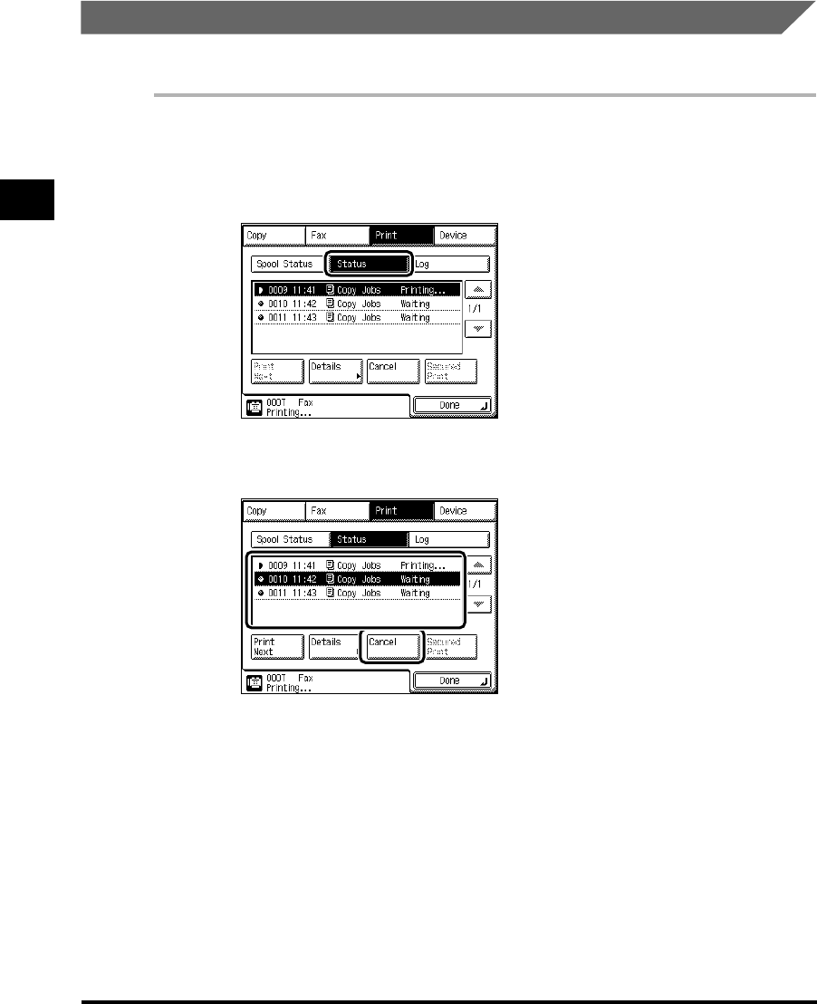
2
Canceling a Reserved Job
2-10
Checking Job and Device Status
Canceling from the System Monitor Screen
You can cancel a job while it is waiting to be processed, or during printing.
1
Press “System Monitor,” and select the Job Type.
2
Press “Status.”
3
Select the job to be canceled, and press “Cancel.”
You cannot select multiple documents and cancel them all at once.
E1L_US_U_.book-INDEX Page 10 Wednesday, May 23, 2001 11:40 PM

2
Canceling a Reserved Job 2-11
Checking Job and Device Status
4
Press “Yes.”
If you do not want to cancel the job, press “No.”
NOTE
•
The canceled document is displayed as <NG> on the Print Log screen.
5
Press “Done.”
The display returns to the Basic Features screen.
E1L_US_U_.book-INDEX Page 11 Wednesday, May 23, 2001 11:40 PM

Priority Printing
2-12
Checking Job and Device Status
2
Priority Printing
When you set priority printing for a job, the machine starts printing the job once the currently
printing document is completed.
1
Press “System Monitor,” and press “Print.”
2
Press “Status.”
3
Select the document for priority printing, and press “Print Next.”
4
Press “Done.”
The display returns to the Basic Features screen.
E1L_US_U_.book-INDEX Page 12 Wednesday, May 23, 2001 11:40 PM
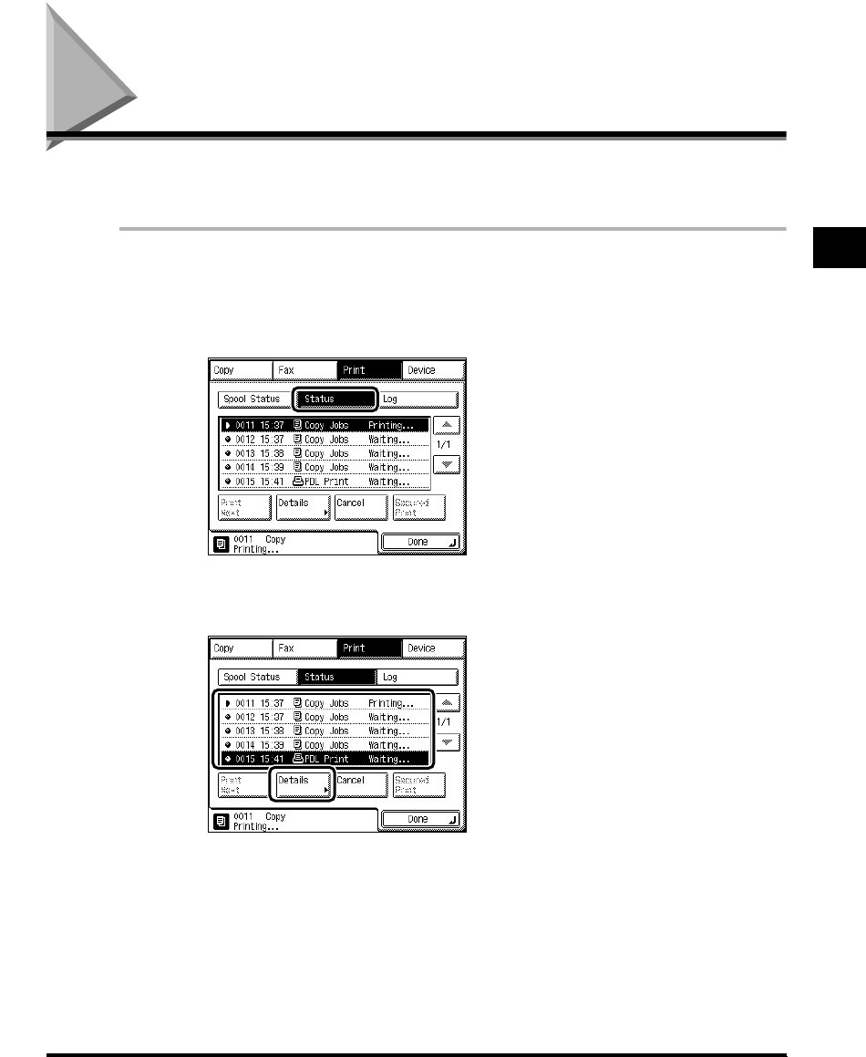
Handling Print Jobs Sent from a Computer 2-13
Checking Job and Device Status
2
Handling Print Jobs Sent from a Computer
You can temporarily stop a print job sent from a computer, or skip an error when a print error
occurs.
1
Press “System Monitor,” and press “Print.”
2
Select “Status.”
3
Select the desired document, and press “Details.”
E1L_US_U_.book-INDEX Page 13 Wednesday, May 23, 2001 11:40 PM

2
Handling Print Jobs Sent from a Computer
2-14
Checking Job and Device Status
4
Press “▼.”
5
Perform handling of the print job.
When you press “Pause,” printing stops temporarily, and the key changes to “Resume.”
When you press “Resume,” printing restarts, and the key changes to “Pause.”
You can continue the print job even when a print error has occurred, by pressing “Auto
Continue,” depending on the type of print error. However, the print output may not be the
same as expected.
When printing is canceled from the computer or when the data is less than the volume of
one page, the print job may not be performed correctly. When you press “Form Feed,” you
can force the print data remaining in memory to be output.
6
When you finish handling the print job, press “Done.”
E1L_US_U_.book-INDEX Page 14 Wednesday, May 23, 2001 11:40 PM

2
Handling Print Jobs Sent from a Computer 2-15
Checking Job and Device Status
7
Press “Done.”
The display returns to the Basic Features screen.
E1L_US_U_.book-INDEX Page 15 Wednesday, May 23, 2001 11:40 PM

Printing Secured Documents
2-16
Checking Job and Device Status
2
Printing Secured Documents
You can print documents that have been assigned a password and sent from a computer.
Documents with a password are called secured documents.
Secured documents waiting to be printed are displayed with a mark to the left of the job
number. To print these documents, you need to enter the correct password. This prevents
other people who do not know the password from observing the contents of the print job.
IMPORTANT
•If the main power is turned OFF, any secured documents are erased.
•The secured document is erased after its printing is completed.
•You cannot change the settings of the secured document before printing it, once it is sent.
1
Press “System Monitor,” and press “Print.”
2
Press “Status.”
3
Select the desired secured document, and press “Secured Print.”
E1L_US_U_.book-INDEX Page 16 Wednesday, May 23, 2001 11:40 PM

CHAPTER
3-1
3
Selecting and Storing Settings to
Suit your Needs
This chapter describes the initial settings and procedures to change them according to your
needs.
Additional Functions Settings Table . . . . . . . . . . . . . . . . . . . . . . . . . . . . . . . . . . . . . . . . .3-2
Setting Specifications That Are Common to Each Function (Common Settings). . . . . . .3-8
Selecting the Initial Function at Power ON . . . . . . . . . . . . . . . . . . . . . . . . . . . . . . . . . . . . . . . . . .3-8
Selecting the Default Display After Auto Clear. . . . . . . . . . . . . . . . . . . . . . . . . . . . . . . . . . . . . .3-10
Setting Entry Tone, Error Tone, and Job Done Tone. . . . . . . . . . . . . . . . . . . . . . . . . . . . . . . . . .3-11
Setting Inch Input . . . . . . . . . . . . . . . . . . . . . . . . . . . . . . . . . . . . . . . . . . . . . . . . . . . . . . . . . . . .3-12
Setting a Paper Drawer for Auto Paper Selection/Auto Drawer Switching. . . . . . . . . . . . . . . . .3-13
Identifying the Type of Paper in a Paper Drawer . . . . . . . . . . . . . . . . . . . . . . . . . . . . . . . . . . . .3-15
Setting the Functions Keys as Keys to Reactivate the Machine . . . . . . . . . . . . . . . . . . . . . . . .3-17
Setting the Energy Consumption in the Sleep Mode . . . . . . . . . . . . . . . . . . . . . . . . . . . . . . . . .3-18
Distinguishing LTRR-size and STMT-size Originals . . . . . . . . . . . . . . . . . . . . . . . . . . . . . . . . . .3-19
Setting a Dedicated Tray for Each Function. . . . . . . . . . . . . . . . . . . . . . . . . . . . . . . . . . . . . . . .3-20
Setting the Printing Priority . . . . . . . . . . . . . . . . . . . . . . . . . . . . . . . . . . . . . . . . . . . . . . . . . . . . .3-22
Registering the Envelope Feeder Attachment . . . . . . . . . . . . . . . . . . . . . . . . . . . . . . . . . . . . . .3-23
Setting the Standard Paper for the Stack Bypass . . . . . . . . . . . . . . . . . . . . . . . . . . . . . . . . . . .3-24
Setting a Standard Mode for Local Printing . . . . . . . . . . . . . . . . . . . . . . . . . . . . . . . . . . . . . . . .3-26
Changing the Language Displayed on the Touch Panel Display. . . . . . . . . . . . . . . . . . . . . . . .3-28
Returning the Common Settings to Their Defaults . . . . . . . . . . . . . . . . . . . . . . . . . . . . . . . . . . .3-29
Setting the Timer (Timer Settings) . . . . . . . . . . . . . . . . . . . . . . . . . . . . . . . . . . . . . . . . .3-30
Setting the Current Date and Time. . . . . . . . . . . . . . . . . . . . . . . . . . . . . . . . . . . . . . . . . . . . . . .3-30
Setting the Time Taken to Initiate Auto Sleep After Finishing Operations . . . . . . . . . . . . . . . . .3-33
Setting the Time Taken for the Display to Return to the Basic Features
Screen After Finishing Operations . . . . . . . . . . . . . . . . . . . . . . . . . . . . . . . . . . . . . . . . . . . . . . .3-34
Setting the Time Taken for the Unit to Quiet Down After the Last Task . . . . . . . . . . . . . . . . . . .3-35
Setting the Time that the Unit’s Power Turns Off on Different Days of the Week . . . . . . . . . . . .3-36
Adjusting the Machine (Adjustment/Cleaning) . . . . . . . . . . . . . . . . . . . . . . . . . . . . . . . .3-38
Fine-adjusting the Zoom When Differences in Original Image and Print Image Occur . . . . . . .3-38
Changing the Saddle Stitch Position . . . . . . . . . . . . . . . . . . . . . . . . . . . . . . . . . . . . . . . . . . . . .3-39
Adjusting the Standard Exposure . . . . . . . . . . . . . . . . . . . . . . . . . . . . . . . . . . . . . . . . . . . . . . .3-40
Setting Staple/Offset to ON/OFF . . . . . . . . . . . . . . . . . . . . . . . . . . . . . . . . . . . . . . . . . . . . . . . .3-41
Printing Reports (Report Settings) . . . . . . . . . . . . . . . . . . . . . . . . . . . . . . . . . . . . . . . . .3-43
Printing the Contents of the Fax Settings . . . . . . . . . . . . . . . . . . . . . . . . . . . . . . . . . . . . . . . . . .3-43
Printing the User’s Data List in the Network Settings . . . . . . . . . . . . . . . . . . . . . . . . . . . . . . . . .3-45
Printing the Contents of the Printer Settings. . . . . . . . . . . . . . . . . . . . . . . . . . . . . . . . . . . . . . . .3-47
E1L_US_U_.book-INDEX Page 1 Wednesday, May 23, 2001 11:40 PM

Additional Functions Settings Table
3-2
Selecting and Storing Settings to Suit your Needs
3
Additional Functions Settings Table
The following settings can be selected or stored from the Additional Functions screen.
(*Indicates the factory default setting.) For more information, consult the following guides:
Copy Settings ..........................................................The Copying Guide
Custom Fax Settings,
Communication Settings in System Settings...........The Facsimile Guide
Mail Box Settings.....................................................The Mail Box Function Guide
Printer Settings........................................................The PS/PCL Printer Guide
Network Settings in System Settings.......................The Network Guide
Remote UI On/Off in System Settings.....................The Remote UI Guide
Additional Function Available settings
Applicabl
e page
Common Settings
Initial Function
Copy*/Mail Box/Fax
Set “System Monitor Screen” as initial function:
On/Off*
Set “Device” as the default for “System Monitor”:
On*/Off
P.3-8
Auto Clear Setting Initial Function*/Selected Function P.3-10
Audible Tones Entry Tone/Error Tone/Job Done Tone (All On*/Off) P.3-11
Inch Entry On*/Off P.3-12
Drawer Eligibility For APS/
ADS
Copy/Printer/Mail Box/Other (Fax) (Stack bypass:
On/ Off*, Drawers: On*/Off)
Copy: Consider Paper Type: On/Off* P.3-13
Store Paper Type Plain*/Recycled/Color/Tracing Paper/Letterhead/
Bond/3-Hole Punch P.3-15
Function Keys Wake Up On/Off* P.3-17
Energy Consumption in Sleep
Mode Low*/High P.3-18
LTRR/STMT Original
Selection Distinguish Manually/Use LTRR Format*/Use STMT
Format P.3-19
E1L_US_U_.book-INDEX Page 2 Wednesday, May 23, 2001 11:40 PM

3
Additional Functions Settings Table 3-3
Selecting and Storing Settings to Suit your Needs
Additional Function Available settings
Applicabl
e page
Common Settings
Tray Designation Tray A: Copy*/Printer*/Fax/Other
Tray B: Copy/Printer/Fax*/Other*
Tray C: Copy/Printer/Fax/Other P.3-20
Printing Priority 1: Copy (Priority)/2:Printer/3:Other P.3-22
Envelope Cassette Env. 1 (COM10*)
Env. 2 (COM10*)
COM10/ISO-B5/Monarch/ISO-C5/DL/Yougata 4 P.3-23
Standard Stack Bypass
Settings On/Off* P.3-24
Standard Local Print Settings
Paper Select: Auto*/Select paper supply
Copies: 1* to 2,000 sets
Finisher:
With the Finisher-J1
Do not Collate/Collate/Offset Collate*/Group/
Offset Group/Staple (Corner)
With the Saddle Finisher-G1+Inner 2way Tray-A1
Do not Collate/Collate*/Offset Collate/Group/
Offset Group/Staple (Corner, Double)
With the Inner 2way Tray-A1
Do not Collate/Collate*/Rotate Collate*/Group/
Rotate Group
With Saddle Finisher-G1+Puncher Unit-K1
Do not Collate/Collate*/Offset Collate/Group/
Offset Group/Staple (Corner, Double) /Hole Punch
Without a Finisher
Do not Collate/Collate*/Rotate Collate/
Group/Rotate Group
Two-sided Print: On/Off*
Erase Document After Printing: On/Off*
Merge Documents: On/Off*
P.3-26
Language Switch On/Off* P.3-28
Initialize Common Settings Initialize P.3-29
Timer Settings
Date & Time Settings
Default setting (12-digit number)
Time Zone Settings: GMT–12:00 to GMT+12:00,
(GMT–5:00*)
Daylight Saving Time Settings: On/Off*
P.3-30
E1L_US_U_.book-INDEX Page 3 Wednesday, May 23, 2001 11:40 PM

3
Additional Functions Settings Table
3-4
Selecting and Storing Settings to Suit your Needs
Additional Function Available settings
Applicabl
e
page
Change Auto Sleep Time 10 Sec., 1, 2*, 10, 15, 20, 30, 40, 50 min., 1 hour, 90
min., 2, 3, 4 hours P.3-33
Change Auto Clear Time 0 (no setting), 1 to 9 min. in one-minute increments,
2 min.* P.3-34
Time Until Unit Quiets Down 0 (no setting), 1 to 9 min. in one-minute increments,
1 min.* P.3-35
Daily Timer Settings Sunday to Saturday, 00:00 to 23:59 in one-minute
increments P.3-36
Adjustment/Cleaning
Zoom Fine Adjustment X/Y: 0*, -1.0% to +1.0% in 0.1% increments P.3-38
Saddle Stitch Position
Adjustment -2.0 mm to +2.0 mm (0 mm*) in 0.25 mm increments P.3-39
Exposure Recalibration 9 Steps, 5* P.3-40
Feeder Cleaning Press “Start” P.5-17
Roller Cleaning Press “Start” P.5-21
Staple/Offset Function On*/Off P.3-41
Report Settings
Custom Settings: Fax –
TX Report On, For Error Only*, Off –
Activity Report Auto Print: On*, Off
Send/Receive Separate: On, Off*
Daily Activity Report Time: On, Off* –
RX Report On, For Error Only, Off* –
Memory Box RX Report On*/Off –
Print List: Fax
P.3-43
Address Book List 1,
Address Book List 2,
Group Destination List,
User’s Data List
Print
Print List: Network P.3-45
User’s Data List Print
E1L_US_U_.book-INDEX Page 4 Wednesday, May 23, 2001 11:40 PM

3
Additional Functions Settings Table 3-5
Selecting and Storing Settings to Suit your Needs
Additional Function Available settings
Applicabl
e
page
Print List: Printer P.3-47
User’s Data List Print
System Settings
System Manager
Settings
P.4-2
System Manager 32 characters max.
System Manager ID 7 digit number max.
System Password 7 digit number max.
E-mail Address 64 characters max.
Contact Information 32 characters max.
Comment 32 characters max.
Department ID
Management
P.4-6
Department ID Management On/Off*
ID/Password Store, Edit, Erase, Limit Impress.
Print Totals Clear, Clear All Totals, Print List
Accept Jobs with Unknown
ID On*/Off
Communications Settings
–
Send Start Speed 33600bps*,14400bps, 9600bps, 7200bps, 4800bps,
2400bps –
Receive Start Speed 33600bps*, 14400bps, 9600bps, 7200bps, 4800bps,
2400bps –
Transfer Setting On/Off* –
Memory Lock Setting On/Off* –
Receive Password Numerals –
PIN Code Access On/Off* –
Device Info Settings Device Name: 32 characters
Location: 32 characters P.4-24
Clear Message Board Erase P.4-25
Auto Offline On/Off* P.4-26
E1L_US_U_.book-INDEX Page 5 Wednesday, May 23, 2001 11:40 PM

3
Additional Functions Settings Table
3-6
Selecting and Storing Settings to Suit your Needs
Additional Function Available settings
Applicabl
e
page
Copy Settings
Standard Key 1, 2 Settings All modes (No setting*) –
Auto Collate On*/Off –
Image Orientation Priority On/Off* –
Job Duration Display On/Off* –
Auto Orientation On*/Off –
Photo Mode On/Off* –
Standard Settings Store, Initialize –
Initialize Copy Settings Initialize –
Custom Fax Settings
User Settings –
Standard Key Settings All Modes (No settings*) –
Unit telephone # Numerals –
Unit Name Alphanumerics, Symbols –
Sender's Names (TTI) Alphanumerics, Symbols –
TX Terminal ID On*/Off –
Density Control 1 to 9, 5* –
Tel Line Type Pulse, Tone* –
Volume Control 0 to 8, 4* –
Standard Settings Store, Initialize –
Store Destinations Store –
TX Settings –
ECM TX On*/Off –
Pause Time 1 to 15 seconds (2 seconds*) –
Auto Redial On*/Off –
E1L_US_U_.book-INDEX Page 6 Wednesday, May 23, 2001 11:40 PM

3
Additional Functions Settings Table 3-7
Selecting and Storing Settings to Suit your Needs
Additional Function Available settings
Applicabl
e
page
Custom Fax Settings
Stamp Document Direct & Memory TX*, Direct TX –
RX Settings –
ECM RX On*/Off –
Received Page Footer On/Off* –
Printer Settings –
Select Cassette Switch A-D Each On*, Off –
Receive Reduction On*/Off –
Two-sided Print On/Off* –
2 On 1 Log On/Off* –
File Settings –
Memory Box Store/Set Confidential, Relay, Batch Sending –
Mail Box Settings
Box Set/Store
Number: 0 to 99
Password: 7 digit number max.
Store Name: 24 characters max.
Doc. Auto Erase: 1, 2, 3, 6, 12 hours, 1, 2, 3*, 7, 30
days, 0 (no limit)
Initialize
–
Photo Mode On/Off* –
Standard Scan Settings Store, Initialize –
E1L_US_U_.book-INDEX Page 7 Wednesday, May 23, 2001 11:40 PM

Setting Specifications That Are Common to Each Function (Common Settings)
3-8
Selecting and Storing Settings to Suit your Needs
3
Setting Specifications That Are Common to Each
Function (Common Settings)
This section describes how to specify the settings that are common to the Copy, Mail Box,
and Fax.
NOTE
•The Common Settings screen is made up of several screens. Use “ ▼” or “ ▲” to scroll to the
desired screen and make the required settings.
•
When the “
▼
” or “
▲
” should be pressed, the indication is displayed in this manual.
Selecting the Initial Function at Power ON
You can specify which screen is displayed when you turn on the main power. The System
Monitor screen can also be specified.
NOTE
•The default settings are as follows:
- Select Initial Function: Copy
- Set “System Monitor Screen” as initial function: Off
- Set “Device” as the default for “System Monitor”: On
1
Call up the desired screen as follows:
(Additional Functions)
Common Settings
Initial Function
E1L_US_U_.book-INDEX Page 8 Wednesday, May 23, 2001 11:40 PM
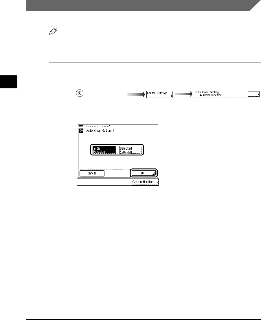
3
Setting Specifications That Are Common to Each Function (Common Settings)
3-10
Selecting and Storing Settings to Suit your Needs
Selecting the Default Display After Auto Clear
You can select which screen to display after Auto Clear has taken place.
NOTE
•The duration for Auto Clear can be set. (See ‘Setting the Time Taken for the Display to Return to
the Basic Features Screen After Finishing Operations,’ on p. 3-34.)
•
The default setting is “Initial Function.”
1
Call up the desired screen as follows:
2
Select the “Initial Function” or “Selected Function,” and press “OK.”
To display the screen set under Initial Function after Auto Clear is performed, press “Initial
Function.” For example, if Copy is set under Initial Function and Auto Clear is performed
after setting the Mail Box function, the display returns to the Copy Basic Features screen.
To display the screen before Auto Clear was performed, press “Select Function.” For
example, if Copy is set under Initial Function and Auto Clear is performed after setting the
Mail Box function, the display returns to the Mail Box Selection screen.
3
Press “Done.”
Repeat this procedure.
The specified mode is set and the display returns to the Basic Features screen.
(Additional Functions)
Auto Clear Setting
E1L_US_U_.book-INDEX Page 10 Wednesday, May 23, 2001 11:40 PM
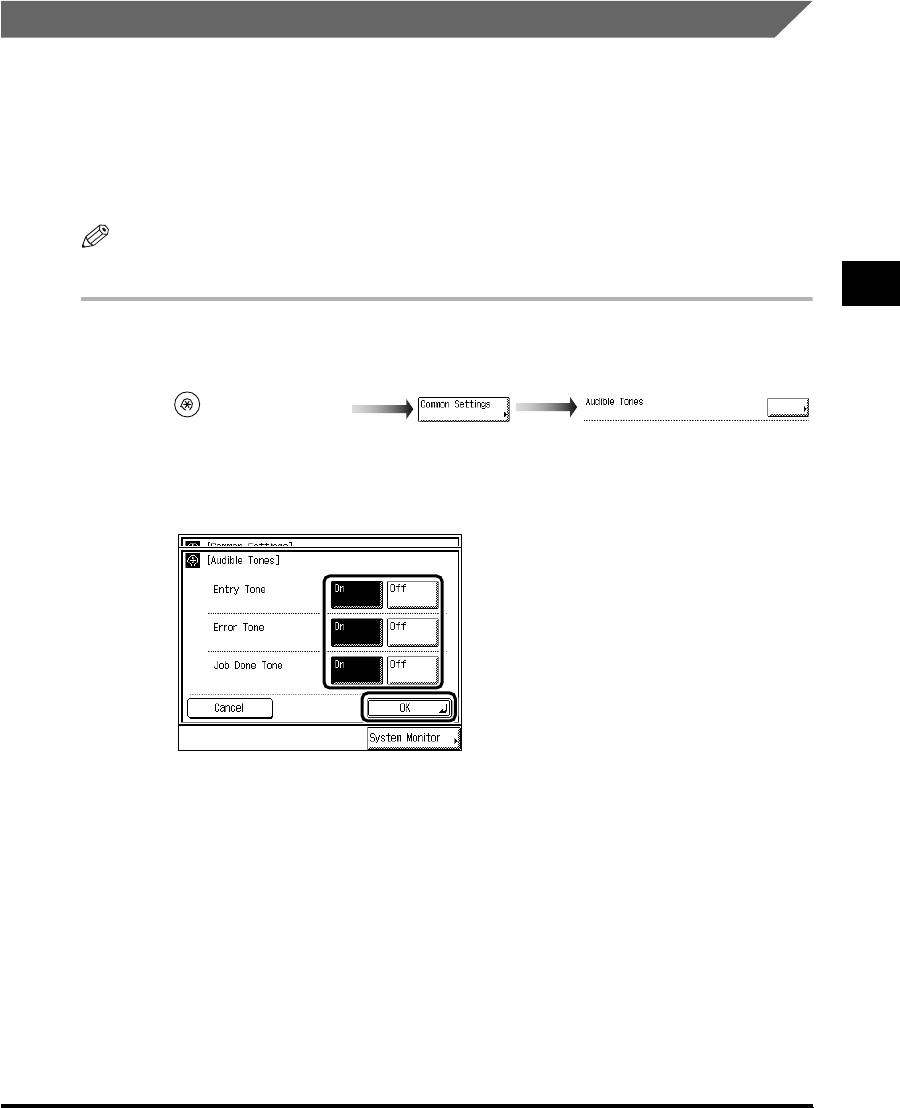
3
Setting Specifications That Are Common to Each Function (Common Settings) 3-11
Selecting and Storing Settings to Suit your Needs
Setting Entry Tone, Error Tone, and Job Done Tone
You can select whether or not to sound audible tones. The following tones sound at the
following times:
• Entry Tone: When pressing keys on the control panel or keys on the touch panel display.
• Error Tone: When a malfunction occurs (e.g., paper jam or operational error).
• Job Done Tone: After the last copy has been made (e.g., outputting, stapling, or faxing is
completed).
NOTE
•The default setting is “On” for all tones.
1
Call up the desired screen as follows:
2
Select “On” or “Off” for Entry Tone, Error Tone, and Job Done Tone,
and press “OK.”
3
Press “Done.”
Repeat this procedure.
The specified mode is set and the display returns to the Basic Features screen.
(Additional Functions)
Audible Tones
E1L_US_U_.book-INDEX Page 11 Wednesday, May 23, 2001 11:40 PM
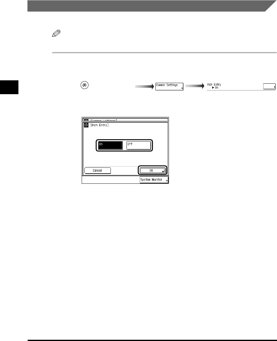
3
Setting Specifications That Are Common to Each Function (Common Settings)
3-12
Selecting and Storing Settings to Suit your Needs
Setting Inch Input
You can display the key for entering values in inches in the numeric entry screens.
NOTE
•The default setting is “On.”
1
Call up the desired screen as follows:
2
Select “On” or “Off,” and press “OK.”
3
Press “Done.”
Repeat this procedure.
The specified mode is set and the display returns to the Basic Features screen.
(Additional Functions)
Inch Entry
E1L_US_U_.book-INDEX Page 12 Wednesday, May 23, 2001 11:40 PM
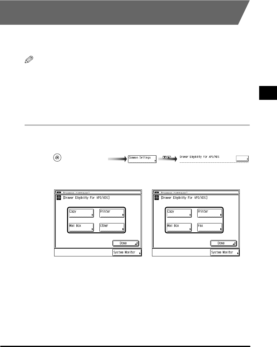
3
Setting Specifications That Are Common to Each Function (Common Settings) 3-13
Selecting and Storing Settings to Suit your Needs
Setting a Paper Drawer for Auto Paper Selection/Auto
Drawer Switching
You can set the paper drawers to be used for Automatic Paper Selection and Auto Drawer
Switching. This setting can be made independently for Copy, Mail Box, and other functions.
This function is useful when different paper drawers are to be used for different purposes.
NOTE
•Paper drawers set to “On” are used for the following functions:
-Auto Paper Selection (APS): The machine automatically selects the appropriate paper size (paper
drawer) for the size of the original and the set ratio (when making a copy), or of the image (when
receiving a fax).
-Auto Drawer Switching (ADS): If a paper drawer runs out of paper during a continuous printing job,
the machine automatically selects another paper drawer with the same paper size and begins
feeding paper from that paper drawer.
•
The default settings are “Off” for the stack bypass and “On” for the paper drawers (1 to 4).
1
Call up the desired screen as follows:
2
Select “Copy,” “Mail Box,” “Printer,” or “Other (“Fax”).”
“Printer” can only be set when the Printer Kit is attached.
“Other” is displayed when the FAX Board is not attached, and sets the paper drawers to be
used for report printing.
“Fax” can only be set when the FAX Board is attached. And, when the FAX Board is
attached, set the paper drawers to be used for report by pressing “Fax.”
(Additional Functions)
Drawer Eligibility For APS/ADS
When only the Printer Kit is
attached When the Printer Kit and the FAX
Board are attached
E1L_US_U_.book-INDEX Page 13 Wednesday, May 23, 2001 11:40 PM
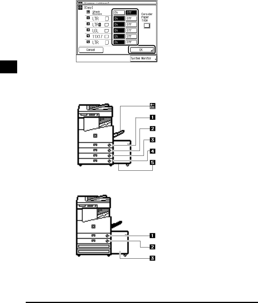
3
Setting Specifications That Are Common to Each Function (Common Settings)
3-14
Selecting and Storing Settings to Suit your Needs
3
Select “On” or “Off” for the stack bypass and each paper drawer,
and press “OK.”
To make the paper drawer eligible for APS/ADS, press “On.”
To make the paper drawer ineligible for APS/ADS, press “Off.”
The number of each paper drawer indicates the following locations:
Stack bypass
Paper drawer 1
Paper drawer 2
Paper drawer 3 (option)
Paper drawer 4 (option)
Paper Deck (option)
When the Cassette Feeding Unit-W1 and the Paper Deck-L1 are attached
The Pedestal and the Paper Deck-L1 are attached
Paper drawer 1
Paper drawer 2
Paper Deck (option)
E1L_US_U_.book-INDEX Page 14 Wednesday, May 23, 2001 11:40 PM

3
Setting Specifications That Are Common to Each Function (Common Settings) 3-15
Selecting and Storing Settings to Suit your Needs
NOTE
•
When you select “Copy,” you can specify whether or not to set priority to paper type.
-When you set “Consider Paper Type” to “On,” paper will not be fed even when paper runs out
during printing, unless other loaded paper matches the size and type. For details of stored
paper types, see ‘Identifying the Type of Paper in a Paper Drawer,’ on p. 3-15.
- When you set “Consider Paper Type” to “Off,” paper will be fed from another paper drawer
when paper runs out during printing, if the same paper size is loaded in that paper drawer.
•
When you select “Printer,” the Stack bypass icon is not displayed.
4
Press “Done.”
Repeat this procedure.
The specified mode is set and the display returns to the Basic Features screen.
Identifying the Type of Paper in a Paper Drawer
You can specify the paper type loaded in each paper drawer.
1
Call up the desired screen as follows:
2
Select the paper drawer for which you want to store the paper type.
The number of each paper drawer indicates the following locations:
(Additional Functions)
Store Paper Type
E1L_US_U_.book-INDEX Page 15 Wednesday, May 23, 2001 11:40 PM

3
Setting Specifications That Are Common to Each Function (Common Settings)
3-16
Selecting and Storing Settings to Suit your Needs
3
Select the paper type loaded in the paper drawer, and press “OK.”
Load the same type of paper as set in each paper drawer.
NOTE
•
For details of paper types, see ‘Available Paper Stock,’ on p. 1-59.
Paper drawer 1
Paper drawer 2
Paper drawer 3 (option)
Paper drawer 4 (option)
Paper Deck (option)
When the Cassette Feeding Unit-W1 and the Paper Deck-L1 are attached.
The Pedestal and the Paper Deck-L1 are attached.
Paper drawer 1
Paper drawer 2
Paper Deck (option)
E1L_US_U_.book-INDEX Page 16 Wednesday, May 23, 2001 11:40 PM

3
Setting Specifications That Are Common to Each Function (Common Settings) 3-17
Selecting and Storing Settings to Suit your Needs
4
Press “Done.”
Repeat this procedure.
The specified mode is set and the display returns to the Basic Features screen.
NOTE
•
The paper types stored here are displayed when selecting paper in each mode, as shown
below.
Setting the Functions Keys as Keys to Reactivate the
Machine
You can set (Copy), (Fax), (Mail Box), and (Scan) as the keys to
reactivate the machine from the Sleep mode.
NOTE
•The default setting is “Off.”
1
Call up the desired screen as follows:
COPY FAX
MAIL BOX
SCAN
(Additional Functions)
Function Key Wake Up
E1L_US_U_.book-INDEX Page 17 Wednesday, May 23, 2001 11:40 PM

3
Setting Specifications That Are Common to Each Function (Common Settings)
3-18
Selecting and Storing Settings to Suit your Needs
2
Select “On” or “Off,” and press “OK.”
3
Press “Done.”
Repeat this procedure.
The specified mode is set and the display returns to the Basic Features Screen.
Setting the Energy Consumption in the Sleep Mode
You can set the amount of energy consumed when the machine is in the Sleep mode.
NOTE
•In the following cases, the energy consumption when the machine enters the Sleep mode is
“High” regardlles of this setting. For details such as setting each function, see the Facsimile
Guide, the Network Guide, or the Printer Guide.
- “Function Keys”: On
- “TCP/IP Settings”
→
“IP Address Settings”
→“Enable DHCP”: On
- “NetWare Settings”: On
- Apple Talk Settings”: On
- When the time is specified, or when a transmission job is reserved, with the FAX Board attached
•
The default setting is “Low.”
1
Call up the desired screen as follows:
(Additional Functions)
Energy Consumption in Sleep Mode
E1L_US_U_.book-INDEX Page 18 Wednesday, May 23, 2001 11:40 PM

3
Setting Specifications That Are Common to Each Function (Common Settings) 3-19
Selecting and Storing Settings to Suit your Needs
2
Select “Low” or “High,” and press “OK.”
3
Press “Done.”
Repeat this procedure.
The specified mode is set and the display returns to the Basic Features screen.
Distinguishing LTRR-size and STMT-size Originals
You can designate the way the machine handles LTRR-size or STMT-size originals placed on
the platen glass.
NOTE
•The default setting is “Use LTRR Format.”
1
Call up the desired screen as follows:
(Additional Functions)
LTRR/STMT Original Selection
E1L_US_U_.book-INDEX Page 19 Wednesday, May 23, 2001 11:40 PM

3
Setting Specifications That Are Common to Each Function (Common Settings)
3-20
Selecting and Storing Settings to Suit your Needs
2
Select “Distinguish Manually,” “Use LTRR Format,” or “Use STMT
Format,” and press “OK.”
When you place an LTRR or STMT-size original on the platen glass:
- If you select “Distinguish Manually”: A screen allowing you to select the original size
appears when scanning.
- If you select “Use LTRR Format”: The machine detects the original as LTRR-size.
- If you select “Use STMT Format”: The machine detects the original as STMT-size.
3
Press “Done.”
Repeat this procedure.
The specified mode is set and the display returns to the Basic Features screen.
Setting a Dedicated Tray for Each Function
You can select the function for which each output tray of the Saddle Finisher-G1 (option) or
the Inner 2way Tray-A1 (option) is to be used.
IMPORTANT
•
This function can be set only when the Inner 2way Tray-A1 is attached.
•
“Fax” is displayed only when the FAX Board (option) is attached.
NOTE
•It is possible to assign a single tray to multiple functions.
•
The default settings are as follows:
-Tray A: Copy, Printer
-Tray B: Fax, Other
-Tray C: No designation
E1L_US_U_.book-INDEX Page 20 Wednesday, May 23, 2001 11:40 PM

3
Setting Specifications That Are Common to Each Function (Common Settings) 3-21
Selecting and Storing Settings to Suit your Needs
1
Call up the desired screen as follows:
2
Select the functions of dedicated output trays A, B, and C, and press
“OK.”
“Fax” is displayed when the Fax board is attached.
IMPORTANT
•
When the paper reaches the stacking limit of the tray while Trays A, B, and C are set as the
designated tray for a certain function, the machine automatically changes the output tray to
another available tray. However, it is recommended that a single output tray should be
assigned to received fax documents to prevent them from being lost.
NOTE
•
Prints of the Mail Box and Report modes are output as “Other.”
•
In the case that the Saddle Finisher-G1 is not attached, Tray C can only be assigned to a
single function, which no other tray is assigned to.
•
When the Saddle Finisher-G1 is attached, the print is output to Tray B, regardless of the
dedicated tray setting if transparency, envelope, heavyweight paper, tracing paper, or free size
paper is selected.
•
When the Saddle Finisher-G1 is attached, the print is output to Tray A regardless of the
dedicated tray setting if the Staple mode is set.
•
When the Inner 2way Tray-A1 is attached, the print is output to Tray A regardless of the
dedicated tray setting, if Transparency, Envelope, Heavyweight paper, Tracing paper, or Free
size paper is selected.
3
Press “Done.”
Repeat this procedure.
The specified mode is set and the display returns to the Basic Features screen.
(Additional Functions)
Tray Designation
When the Saddle Finisher-G1 is
attached When the Inner 2way Tray-A1 is
attached
E1L_US_U_.book-INDEX Page 21 Wednesday, May 23, 2001 11:40 PM

3
Setting Specifications That Are Common to Each Function (Common Settings)
3-22
Selecting and Storing Settings to Suit your Needs
Setting the Printing Priority
You can set the printing priority. A job that is set to a high priority is printed preferentially after
the job currently being processed.
NOTE
•Priority printing will not take place even when you set the highest priority, until the current job is
completed. However, if the current job is paused, printing of the job from a function with higher
priority may start, depending on the settings.
•
The default settings are as follows:
- Copy: 1 (Priority)
-Printer: 2
- Other: 3 (1, 2, and 3 indicate priority sequence.)
1
Call up the desired screen as follows:
2
Select the printing priority, and press “OK.”
Setting “1” sets the highest printing priority.
You can select “Printer” only when the Printer Kit is attached.
Prints of the Mail Box, Fax, and Report functions are output as “Other.”
NOTE
•
When the same printing priority has been specified for multiple functions, printing starts from
whichever of the functions is set to print first.
3
Press “Done.”
Repeat this procedure.
The specified mode is set and the display returns to the Basic Features screen.
(Additional Functions)
Printing Priority
E1L_US_U_.book-INDEX Page 22 Wednesday, May 23, 2001 11:40 PM
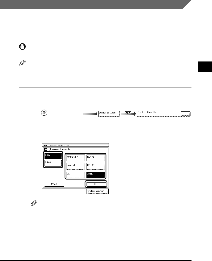
3
Setting Specifications That Are Common to Each Function (Common Settings) 3-23
Selecting and Storing Settings to Suit your Needs
Registering the Envelope Feeder Attachment
You can use the paper drawer 1 as an envelope cassette, if you attach the Envelope Feeder
Attachment and set the size switch and the paper size dial. The envelope cassette can hold
the following six types of envelopes: COM10/ISO-B5/Monarch/ISO-C5/DL/Yougata 4.
This section describes how to specify the type of envelopes and which cassette they are to
be loaded in.
IMPORTANT
•
When the Envelope Feeder Attachment (option) is not attached, this procedure is not necessary.
NOTE
•The default settings are as follows:
- ENV.1: COM 10
- ENV.2: COM 10
1
Call up the desired screen as follows:
2
Press “ENV. 1” or “ENV. 2” → select the type of envelope → press
“OK.”
NOTE
•
For the size switch set in Envelope Cassette, select the same type as the envelope.
3
Press “Done.”
Repeat this procedure.
The specified mode is set and the display returns to the Basic Features screen.
(Additional Functions)
Envelope Cassette
E1L_US_U_.book-INDEX Page 23 Wednesday, May 23, 2001 11:40 PM

3
Setting Specifications That Are Common to Each Function (Common Settings)
3-24
Selecting and Storing Settings to Suit your Needs
Setting the Standard Paper for the Stack Bypass
Stores the default settings for the Stack Bypass Setting. By pressing “Stack Bypass” when
making reserved prints, you can reserve by the mode that you stored here.
If the Standard Stack Bypass Settings is stored when using the fax, you can receive by using
the stack bypass.
NOTE
•When using the stack bypass as a paper source for the Copy, Mail Box, and Fax functions, you
must select the stack bypass as the Auto Paper Drawer Selection.
•
The default setting is “Off.”
1
Call up the desired screen as follows:
2
Select “On,” and press “Store.”
If you select “Off,” proceed to step 5.
(Additional Functions)
Standard Stack Bypass Settings
E1L_US_U_.book-INDEX Page 24 Wednesday, May 23, 2001 11:40 PM

3
Setting Specifications That Are Common to Each Function (Common Settings) 3-25
Selecting and Storing Settings to Suit your Needs
3
Select the paper size, and press “Next.”
NOTE
•
To select inch size paper, press “A/B-size.”
•
To select free size paper, press “Free Size.”
•
To select envelope, press “Envelope” and select the type of envelope. Then press “OK”
→
“OK,” and proceed to step 5.
4
Select the paper type, and press “OK.”
5
Press “OK.”
E1L_US_U_.book-INDEX Page 25 Wednesday, May 23, 2001 11:40 PM

3
Setting Specifications That Are Common to Each Function (Common Settings)
3-26
Selecting and Storing Settings to Suit your Needs
6
Press “Done.”
Repeat this procedure.
The specified mode is set and the display returns to the Basic Features screen.
Setting a Standard Mode for Local Printing
When you want to print documents in the Mail Box without changing the original settings set
when they were scanned, or when you want to print documents in the Mail Box sent from a
personal computer after changing the print settings, you can print using the Local Print
Standard settings set in this section. It also prints with the standard Local Print settings when
you merge multiple documents.
NOTE
•The default settings are as follows: (*indicates factory default setting.)
•Paper Select (Paper source): Auto*
• Copies: 1*
• Finisher
- With the Finisher-J1:
Do not Collate/Collate/Offset Collate*/Group/Offset Group/Staple (Corner)
- With the Saddle Finisher G1+Inner 2way Tray-A1:
Do not Collate/Collate*/Offset Collate/Group/Offset Group/Staple (Corner, Double)
- With the Inner 2way Tray-A1:
Do not Collate/Collate*/Rotate Collate/Group/Rotate Group
- With the Saddle Finisher-G1 and Puncher Unit-K1:
Do not Collate/Collate*/Offset Collate/Group/Offset Group/Staple (Corner, Double)/Hole
Punch
- With no Finisher:
Do not Collate/Collate*/Rotate Collate/Group/Rotate Group
•Two-sided Print (On/Off*)
•Erase Document After Printing (On/Off*)
• Merge Documents (On/Off*)
E1L_US_U_.book-INDEX Page 26 Wednesday, May 23, 2001 11:40 PM

3
Setting Specifications That Are Common to Each Function (Common Settings) 3-27
Selecting and Storing Settings to Suit your Needs
1
Call up the desired screen as follows:
2
Set each mode, and press “Done.”
Paper Select: Select the paper source.
Copies: Set the number of copies from 1 set to 2,000 sets.
Finisher: Set the type of collating.
Two-sided Print: Set whether or not to perform two-sided printing.
Erase Document After Printing: Set whether or not to erase a document after printing.
Merge Documents: Set whether or not to merge documents when you select multiple
documents.
3
Press “Done.”
Repeat this procedure.
The specified mode is set and the display returns to the Basic Features screen.
(Additional Functions)
Standard Local Print Settings
E1L_US_U_.book-INDEX Page 27 Wednesday, May 23, 2001 11:40 PM

3
Setting Specifications That Are Common to Each Function (Common Settings)
3-28
Selecting and Storing Settings to Suit your Needs
Changing the Language Displayed on the Touch Panel
Display
You can select the language displayed on the touch panel display.
NOTE
•When Language Switch is set to “On,” some characters will be restricted and not be able to be
entered. To enable all characters to be entered, set to “Off.”
•
Even when Language Switch is set to “On,” there are some languages which cannot be displayed.
•
The default setting is
“
Off.
”
1
Call up the desired screen as follows:
2
Press “On,” and select the desired language.
Press “▼” or “▲” to display the desired the language.
If you do not want to change the panel language, press “Cancel.”
3
Press “OK.”
The display returns to the Basic Features screen, and the panel language changes.
(Additional Functions)
Language Switch
E1L_US_U_.book-INDEX Page 28 Wednesday, May 23, 2001 11:40 PM

3
Setting Specifications That Are Common to Each Function (Common Settings) 3-29
Selecting and Storing Settings to Suit your Needs
Returning the Common Settings to Their Defaults
With this function you can return the common settings to their defaults (initial settings).
1
Call up the desired screen as follows:
2
Select “Yes.”
To cancel initialization, select “No.”
The screen shown below is displayed for about two seconds.
3
Press “Done.”
Repeat this procedure.
The specified mode is set and the display returns to the Basic Features screen.
(Additional Functions)
Initialize Common Settings
E1L_US_U_.book-INDEX Page 29 Wednesday, May 23, 2001 11:40 PM
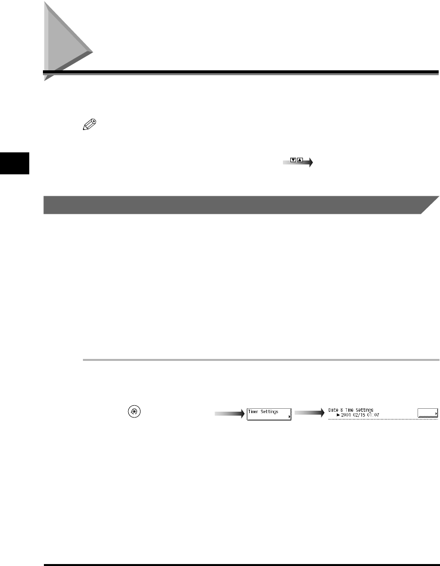
Setting the Timer (Timer Settings)
3-30
Selecting and Storing Settings to Suit your Needs
3
Setting the Timer (Timer Settings)
You can set the current date and time, and specify the time taken for the machine to enter the
Sleep mode.
NOTE
•The Timer Settings screen is made up of several screens. Use “ ▼” or “▲” to scroll to the desired
screen and make the required settings.
•
When “
▼
” or “
▲
” should be pressed, the indication is displayed in this manual.
Setting the Current Date and Time
You can set the current date and time. The date and time set here is also used as the time
setting when required for functions.
−GMT : The time at the Greenwich Observatory in England is called GMT
(Greenwich Mean Time).
−Time Zone : The standard time zones of the world are expressed globally in
terms of the difference in hours (± up to 12 hours) from GMT (± 0
hours). A time zone is a region throughout which this time
difference is the same.
−Daylight Saving Time : In some countries, time is advanced throughout the summer
season. The period in which this is applied is called <daylight
saving time>.
1
Call up the desired screen as follows:
(Additional Functions)
Date & Time Settings
E1L_US_U_.book-INDEX Page 30 Wednesday, May 23, 2001 11:40 PM
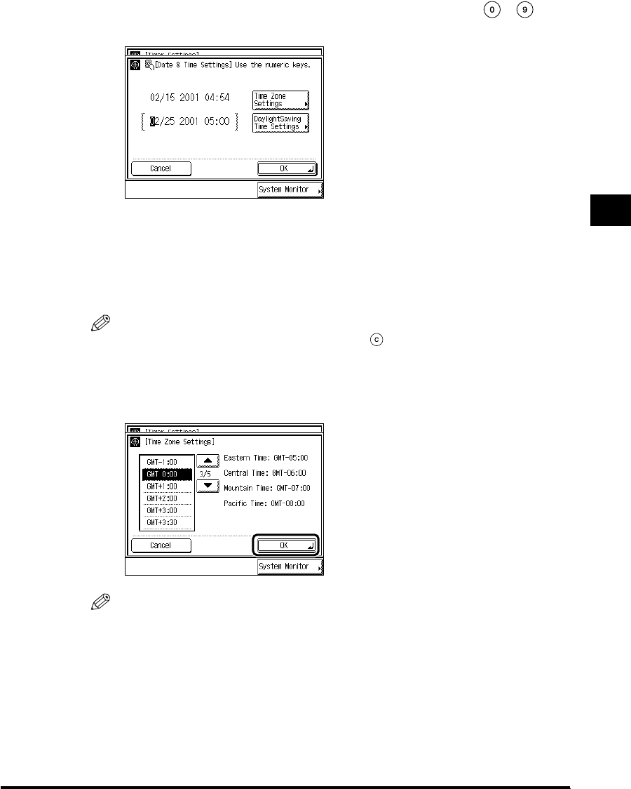
3
Setting the Timer (Timer Settings) 3-31
Selecting and Storing Settings to Suit your Needs
2
Enter the current date (month, day, year) and time with -
(numeric keys).
Enter the date, and the time in 24-hour clock as four digits without a space.
Enter all four digits for the year ranging from 2000 to 2038.
Examples: MAY 6 → 0506
7:05 a.m. → 0705
11:18 p.m. → 2318
NOTE
•
If you make a mistake when entering values, press (Clear), and enter the values again.
●When setting the Time Zone Settings:
Press “Time Zone Settings,” and select the time zone where the machine is
located, and press “OK.”
NOTE
•
The default setting is “GMT-5:00.”
Eastern time (US/Canada) : GMT-5:00
Central time (US/Canada) : GMT-6:00
Mountain time (US/Canada) : GMT-7:00
Pacific time (US/Canada) : GMT-8:00
•
Press “
▼
” or “
▲
” to scroll the list.
E1L_US_U_.book-INDEX Page 31 Wednesday, May 23, 2001 11:40 PM

3
Setting the Timer (Timer Settings)
3-32
Selecting and Storing Settings to Suit your Needs
●When setting the Daylight Saving Time Settings:
Press “Daylight Saving Time Settings” → press “On” → press “Start Date.”
Select “Month” → “Week” → “Day” to specify each of them.
Enter the time using “–” and “+,” and press “OK.”
Press “End Date” and make the settings in the same way as the above.
NOTE
•
When you make the Daylight Saving Time settings, the machine automatically sets the
standard time of the machine one-hour forward at the specified date and time.
•
The default setting is “Off.”
•
You can also set the time with - (numeric keys).
•
The time can be set from 0 to 23 (in one-hour increments).
E1L_US_U_.book-INDEX Page 32 Wednesday, May 23, 2001 11:40 PM

3
Setting the Timer (Timer Settings) 3-33
Selecting and Storing Settings to Suit your Needs
3
Press “OK.”
4
Press “Done.”
Repeat this procedure.
The specified mode is set and the display returns to the Basic Features screen.
Setting the Time Taken to Initiate Auto Sleep After
Finishing Operations
If the machine is not operated (no keys are pressed) for a certain period of time, the control
panel power switch automatically switches OFF to save power. The machine then enters the
Sleep mode.
NOTE
•The default setting is “2 minutes.”
1
Call up the desired screen as follows:
(Additional Functions)
Change Auto Sleep Time
E1L_US_U_.book-INDEX Page 33 Wednesday, May 23, 2001 11:40 PM
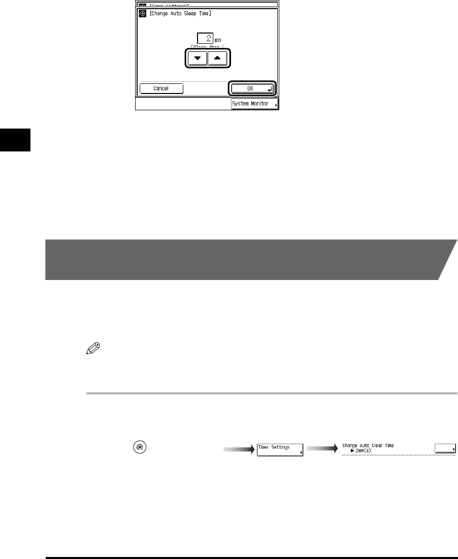
3
Setting the Timer (Timer Settings)
3-34
Selecting and Storing Settings to Suit your Needs
2
Enter the desired Auto Sleep Time with “▼” or “▲,” and press “OK.”
The Auto Sleep Time settings are 10 seconds, 1, 2, 10, 15, 20, 30, 40, 50 minutes, 1 hour,
90 minutes, 2, 3, and 4 hours.
3
Press “Done.”
Repeat this procedure.
The specified mode is set and the display returns to the Basic Features screen.
Setting the Time Taken for the Display to Return to the
Basic Features Screen After Finishing Operations
If the machine is not operated (no keys are pressed) for a certain period of time, the display
returns to the Basic Features screen (standard setting) of the selected function.
This period of time is called “Auto Clear Time.” Auto Clear Time can be set from 1 to 9
minutes in one-minute increments, and can also be set to “Off.”
NOTE
•The default setting is “2 minutes.”
•
When “0” is selected, the Auto Clear function is not set.
1
Call up the desired screen as follows:
(Additional Functions)
Change Auto Clear Time
E1L_US_U_.book-INDEX Page 34 Wednesday, May 23, 2001 11:40 PM

3
Setting the Timer (Timer Settings) 3-35
Selecting and Storing Settings to Suit your Needs
2
Enter the desired time period using “–” or “+,” and press “OK.”
The Auto Clear Time settings are from 0 to 9 minutes (in one-minute increments).
You can also enter values using -(numeric keys).
3
Press “Done.”
Repeat this procedure.
The specified mode is set and the display returns to the Basic Features screen.
Setting the Time Taken for the Unit to Quiet Down After the
Last Task
This machine enters the Quiet mode after a specified amount of time has elapsed following a
print job or after a key has been pressed. On this screen you can specify the amount of time
that must be taken before entering the Quiet mode.
NOTE
•The default setting is “1 minute.”
1
Call up the desired screen as follows:
(Additional Functions)
Time Until Unit Quiets Down
E1L_US_U_.book-INDEX Page 35 Wednesday, May 23, 2001 11:40 PM
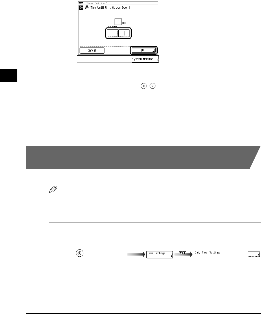
3
Setting the Timer (Timer Settings)
3-36
Selecting and Storing Settings to Suit your Needs
2
Enter the desired time period with “–” or “+,” and press “OK.”
The Time Until Unit Quiets Down settings are from 0 to 9 minutes (in one-minute
increments).
You can also enter values using -(numeric keys).
3
Press “Done.”
Repeat this procedure.
The specified mode is set and the display returns to the Basic Features screen.
Setting the Time that the Unit’s Power Turns Off on
Different Days of the Week
You can set the time that the machine automatically turns off for each day of the week.
NOTE
•Setting range: Daily from Sunday to Saturday, 00:00 to 23:59 in one-minute increments
•
When Auto Clear Time and Daily Timer are both set, Auto Clear Time has priority.
•
The default setting is “No setting.”
1
Call up the desired screen as follows:
(Additional Functions)
Daily Timer Settings
E1L_US_U_.book-INDEX Page 36 Wednesday, May 23, 2001 11:40 PM
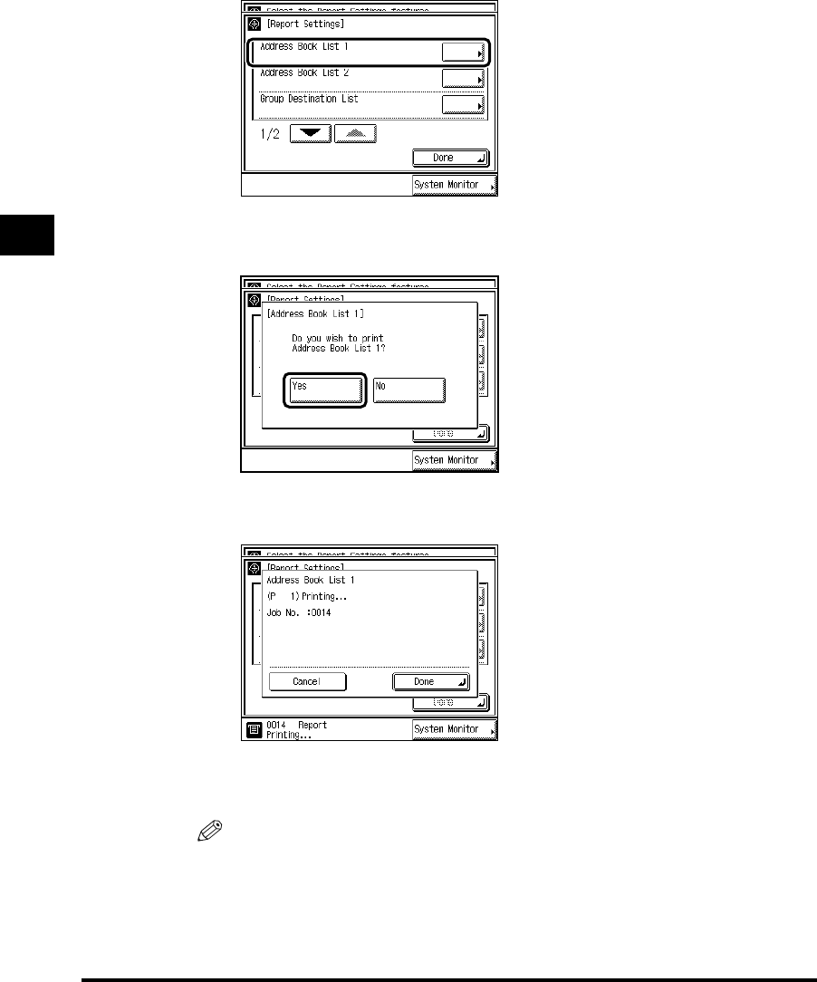
3
Printing Reports (Report Settings)
3-44
Selecting and Storing Settings to Suit your Needs
3
Press “Address Book List 1.”
4
Press “Yes.”
If you do not want to print, press “No.”
The screen below appears, and printing starts.
When printing is completed, <Print Completed> appears.
To close the screen while printing, press “Done.”
NOTE
•
To cancel printing, press “Cancel.”
E1L_US_U_.book-INDEX Page 44 Wednesday, May 23, 2001 11:40 PM

3
Printing Reports (Report Settings) 3-45
Selecting and Storing Settings to Suit your Needs
5
Press “Done.”
Repeat this procedure.
The specified mode is set and the display returns to the Basic Features screen.
Printing the User’s Data List in the Network Settings
You can print the user’s data list in the Network Settings when the Network Interface Adapter
is attached.
1
Call up the desired screen as follows:
2
Press “Network” under <Print List>.
When both the FAX Board and Printer Kit are not attached, and the Network Interface
Adapter is attached, this procedure is not necessary.
(Additional Functions)
When the FAX Board, Network
Interface Adapter, and Printer Kit
are attached
When the Network Interface
Adapter and Printer Kit are
attached
E1L_US_U_.book-INDEX Page 45 Wednesday, May 23, 2001 11:40 PM
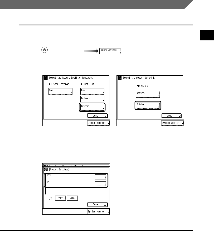
3
Printing Reports (Report Settings) 3-47
Selecting and Storing Settings to Suit your Needs
5
Press “Done.”
Repeat this procedure.
The specified mode is set and the display returns to the Basic Features screen.
Printing the Contents of the Printer Settings
When the Printer Kit is attached, you can print the contents of the printer setting.
1
Call up the desired screen as follows:
2
Press “Printer” under <Print List>.
3
Select the type of report you want to print.
(Additional Functions)
W
hen the FAX Board, Network
I
nterface Adapter, and Printer Kit
a
re attached
When the Network Interface
Adapter and Printer Kit are
attached
E1L_US_U_.book-INDEX Page 47 Wednesday, May 23, 2001 11:40 PM

3
Printing Reports (Report Settings)
3-48
Selecting and Storing Settings to Suit your Needs
4
Press “Yes.”
If you do not want to print, press “No.”
When printing is completed, the screen returns to step 3.
5
Press “Done.”
Repeat this procedure.
The specified mode is set and the display returns to the Basic Features screen.
E1L_US_U_.book-INDEX Page 48 Wednesday, May 23, 2001 11:40 PM

CHAPTER
4-1
4
System Manager Settings
This chapter describes settings that can be made by the person in charge of the machine’s
operation, such as the system manager.
Setting Specifications of System Manager Settings (System Manager Settings). . . . . . .4-2
Setting the Department ID Management . . . . . . . . . . . . . . . . . . . . . . . . . . . . . . . . . . . . .4-6
Storing the Department ID and Password, and Impression Limit . . . . . . . . . . . . . . . . . . . . . . . .4-6
Changing the Password and Impression Limit . . . . . . . . . . . . . . . . . . . . . . . . . . . . . . . . . . . . .4-10
Erasing the Department ID and Password. . . . . . . . . . . . . . . . . . . . . . . . . . . . . . . . . . . . . . . . .4-13
Checking and Printing Counter Information . . . . . . . . . . . . . . . . . . . . . . . . . . . . . . . . . . . . . . . .4-15
Erasing Print Totals . . . . . . . . . . . . . . . . . . . . . . . . . . . . . . . . . . . . . . . . . . . . . . . . . . . . . . . . . . .4-19
Specifying Whether or Not to Accept Print Jobs of Unknown ID . . . . . . . . . . . . . . . . . . . . . . . .4-21
Setting Device Information (Device Information Settings) . . . . . . . . . . . . . . . . . . . . . . .4-24
Erasing the Message Board (Clear Message Board). . . . . . . . . . . . . . . . . . . . . . . . . . .4-25
Setting the Auto Offline On/Off (Auto Offline). . . . . . . . . . . . . . . . . . . . . . . . . . . . . . . . .4-26
E1L_US_U_.book-INDEX Page 1 Wednesday, May 23, 2001 11:40 PM

Setting Specifications of System Manager Settings (System Manager Settings)
4-2
System Manager Settings
4
Setting Specifications of System Manager
Settings (System Manager Settings)
You can set a password for the system manager. Once the System Manager ID/Password is
set, restrictions can be placed on storing or changing the System Settings.
IMPORTANT
•
Attaching the Card Reader-C1 erases the System Manager ID and Password already stored.
NOTE
•When the Card Reader-C1 is attached, the number of 1 to 300 cannot be stored for the System
Manager ID.
•For details on how to enter the characters, see ‘Entering Characters from the Touch Panel
Display,’ on p. 1-31.
•The maximum number of characters you can assign for a name, contact, and comment is 32, and
for an e-mail address is 64.
•The maximum number of digits you can store for the System Manager ID and Password is seven.
If you store either with less than seven digits, the machine stores them with leading zeroes, as
follows:
•Example: When <321> is entered → <0000321> is stored.
1
Call up the desired screen as follows:
When the System Manager ID/Password is set, enter the System Manager ID and System
Password after pressing “System Settings.” Then, press (ID).
2
Press “System Manager,” and enter the name of the system
manager.
(Additional Functions)
E1L_US_U_.book-INDEX Page 2 Wednesday, May 23, 2001 11:40 PM

4
Setting Specifications of System Manager Settings (System Manager Settings) 4-3
System Manager Settings
3
Press “System Manager ID,” and enter a number of up to seven
digits with -(numeric keys) for the new System Manager ID.
You must enter the System Manager ID.
You cannot store a System Manager ID with only the number <0>, such as <0000000>.
NOTE
•
You can delete the number you entered by pressing (Clear).
4
Press “System Password” → use -(numeric keys) to enter a
number of up to seven digits for the new System Password → press
“Next.”
You cannot store a System Settings Password with only the number <0>, such as
<0000000>.
Press “Next” even when not setting a System Password.
NOTE
•
You can delete the number you entered by pressing (Clear).
E1L_US_U_.book-INDEX Page 3 Wednesday, May 23, 2001 11:40 PM

4
Setting Specifications of System Manager Settings (System Manager Settings)
4-4
System Manager Settings
5
Press “E-mail Address,” and enter an e-mail address for the system
manager.
6
Press “Contact Information,” and enter where to contact the system
manager.
7
Press “Comment,” and enter any comment for the system manager.
E1L_US_U_.book-INDEX Page 4 Wednesday, May 23, 2001 11:40 PM

4
Setting Specifications of System Manager Settings (System Manager Settings) 4-5
System Manager Settings
8
Once you have completed all settings, press “OK.”
9
Press “Done.”
Repeat this procedure.
The display returns to the Basic Features screen.
E1L_US_U_.book-INDEX Page 5 Wednesday, May 23, 2001 11:40 PM
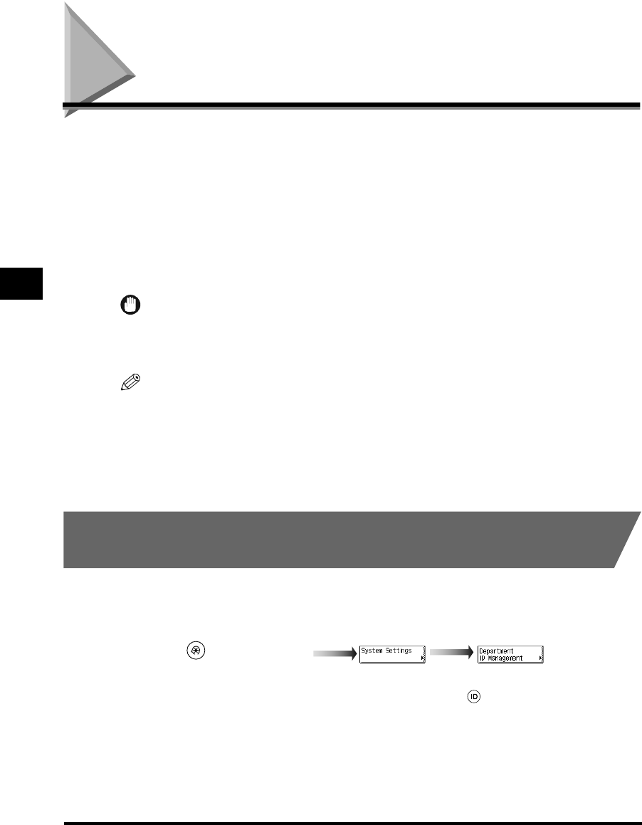
Setting the Department ID Management
4-6
System Manager Settings
4
Setting the Department ID Management
By storing a Department ID and Password for each department, you can set the machine so
that its functions can be used only after the correct password has been entered. This is
called “Department ID Management.” Department IDs and Passwords for up to 300
departments can be stored. This function allows you to check the print totals for each
department, for management purposes.
With Department ID Management, the following operations can be performed:
• Specifying whether or not to use Department ID Management
• Storing the Department ID and the Password
• Setting the Impression Limit for each department.
IMPORTANT
•
This function switches to Card ID Management when the Control Card (option) is attached. Card ID
Management automatically manages the ID according to department (See ‘Card Reader-C1,’ on p.
7-80.)
NOTE
•The maximum number of digits you can store for the Department ID and Password is seven. If
you store either with less than seven digits, the machine stores them with leading zeroes, as
follows:
- Example: When <321> is entered
→
<0000321> is stored
•The default setting is “Off.”
Storing the Department ID and Password, and Impression
Limit
1
Call up the desired screen as follows:
When the System Manager ID/Password is set, enter the System Manager ID and System
Password after pressing “System Settings.” Then, press (ID).
(Additional Functions)
Department ID
Management
E1L_US_U_.book-INDEX Page 6 Wednesday, May 23, 2001 11:40 PM
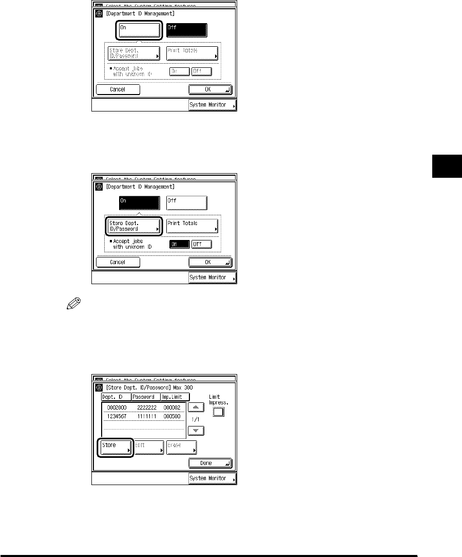
4
Setting the Department ID Management 4-7
System Manager Settings
2
Press “On.”
If you do not want to store a password, proceed to step 3.
3
Press “Store Dept. ID/Password.”
NOTE
•
For details concerning print totals, see ‘Checking and Printing Counter Information,’ on p. 4-
15.
4
Press “Store.”
E1L_US_U_.book-INDEX Page 7 Wednesday, May 23, 2001 11:40 PM

4
Setting the Department ID Management
4-8
System Manager Settings
5
Press “Department ID” → enter the Department ID with -
(numeric keys) → press “Password” → enter the password in the
same way.
You cannot store a Department ID with only the number <0>, such as <0000000>.
NOTE
•
When a password is not stored, you can use this machine by entering only the Department ID.
6
Press “Impression Limit,” and enter the desired value with -
(numeric keys).
NOTE
•
The number you can set for Impression Limit is from 0 to 999999. Once the Impression Limit
is set, you cannot exceed the number entered.
•
A two-sided print is counted as <2>.
E1L_US_U_.book-INDEX Page 8 Wednesday, May 23, 2001 11:40 PM

4
Setting the Department ID Management 4-9
System Manager Settings
7
Press “OK.”
8
Set the Impression Limit, and press “Done.”
To make the “Impression Limit” set in the step 6 effective, press “Limit Impress.”
“Limit Impress.” cannot be selected for a particular department.
9
Press “OK.”
NOTE
•
When you select “On,” Department ID Management is enabled. (See ‘Entering the
Department ID and Password,’ on p. 1-36.)
E1L_US_U_.book-INDEX Page 9 Wednesday, May 23, 2001 11:40 PM
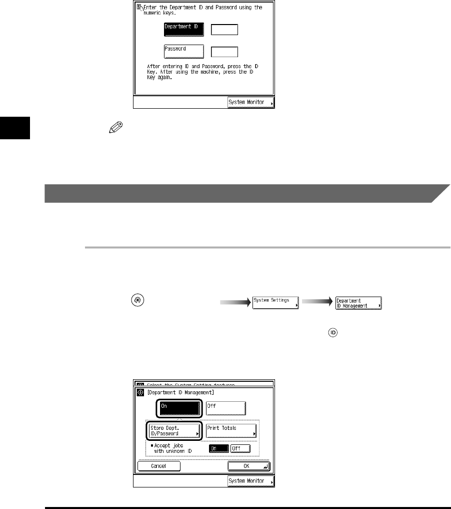
4
Setting the Department ID Management
4-10
System Manager Settings
10
Press “Done.”
Repeat this procedure.
When the screen below appears, enter the Department ID and Password.
NOTE
•
For details of how to enter the Department ID and Password, see ‘Entering the Department ID
and Password,’ on p. 1-36.
Changing the Password and Impression Limit
The following instructions describe how to change the Password and Impression Limit you
have stored.
1
Call up the desired screen as follows:
When the System Manager ID/Password is set, enter the System Manager ID and System
Password after pressing “System Settings.” Then, press (ID).
2
Press “On,” and press “Store Dept. ID/Password.”
(Additional Functions)
E1L_US_U_.book-INDEX Page 10 Wednesday, May 23, 2001 11:40 PM

4
Setting the Department ID Management 4-11
System Manager Settings
3
Use “▼” and “▲” to display the Password you want to change →
select the Password → press “Edit.”
4
Enter the Password with -(numeric keys), and press “OK.”
To change Impression Limit, press “Impression Limit,” and enter the desired value
using - (numeric keys). Then press “OK.”
You cannot store a password with only the number <0>, such as <0000000>.
NOTE
•
The number you can set for Impression Limit is from 0 to 999999. Once the Impression Limit
is set, you cannot exceed the number entered.
•
A two-sided print is counted as <2>.
•
You cannot change the Department IDs.
E1L_US_U_.book-INDEX Page 11 Wednesday, May 23, 2001 11:40 PM
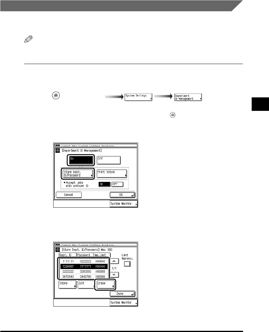
4
Setting the Department ID Management 4-13
System Manager Settings
Erasing the Department ID and Password
The following instructions describe how to erase the Department ID and Password you have
stored.
NOTE
•When using Department ID Management with Card Reader-C1, you cannot erase the
Department ID.
1
Call up the desired screen as follows:
When the System Manager ID/Password is set, enter the System Manager ID and System
Password after pressing “System Settings.” Then, press (ID).
2
Press “On,” and press “Store Dept. ID/Password.”
3
Use “▼” and “▲” to display the Department and its settings that you
want to erase → select the Department → press “Erase.”
(Additional Functions)
E1L_US_U_.book-INDEX Page 13 Wednesday, May 23, 2001 11:40 PM
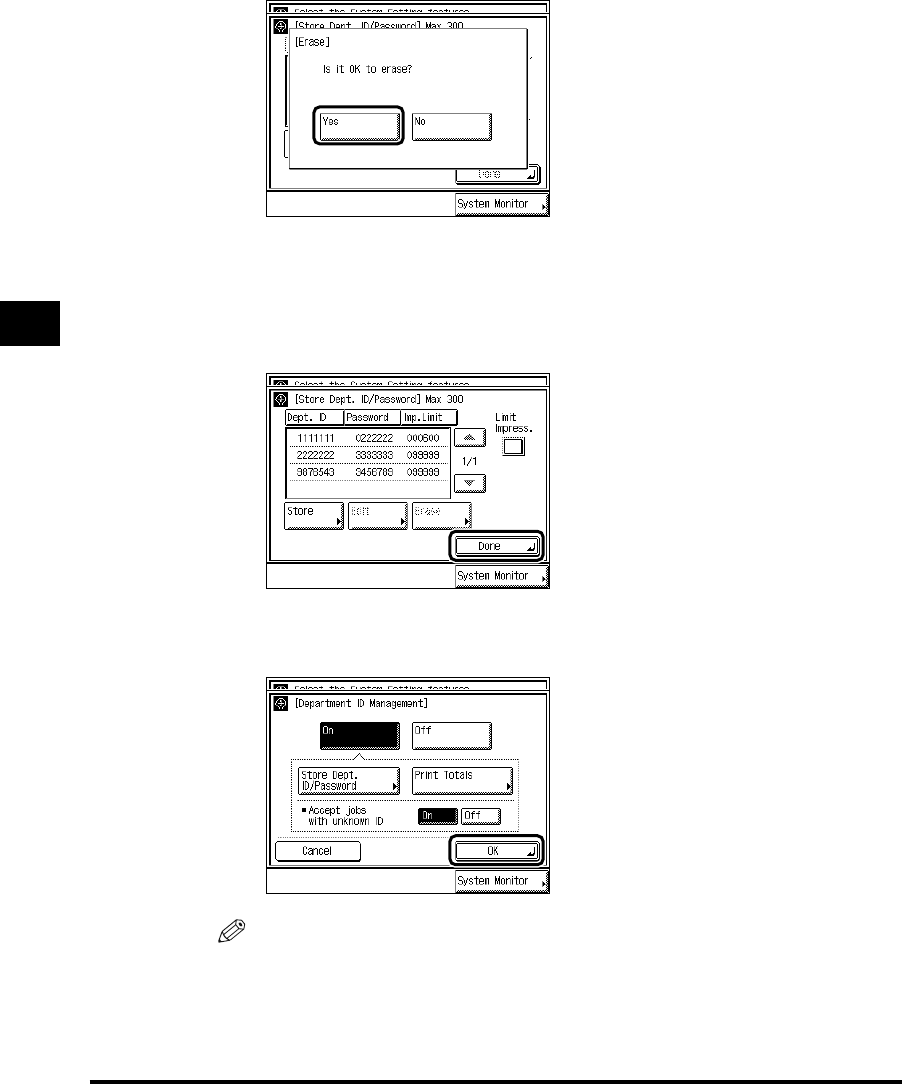
4
Setting the Department ID Management
4-14
System Manager Settings
4
Press “Yes.”
If you do not want to erase the Department and its settings, press “No.”
The selected Department and its settings are erased.
5
Press “Done.”
6
Press “OK.”
NOTE
•
When you select “On,” Department ID Management is enabled. (See ‘Entering the
Department ID and Password,’ on p. 1-36.)
E1L_US_U_.book-INDEX Page 14 Wednesday, May 23, 2001 11:40 PM
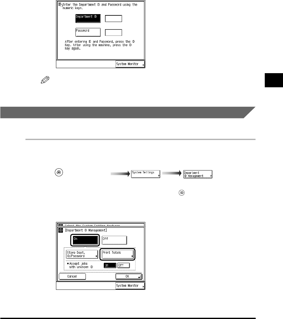
4
Setting the Department ID Management 4-15
System Manager Settings
7
Press “Done.”
Repeat this procedure.
When the screen below appears, enter the Department ID and Password.
NOTE
•
For details of how to enter the Department ID and Password, see ‘Entering the Department ID
and Password,’ on p. 1-36.
Checking and Printing Counter Information
You can display and print a list of the paper count for each department.
1
Call up the desired screen as follows:
When the System Manager ID/Password is set, enter the System Manager ID and System
Password after pressing “System Settings.” Then, press (ID).
2
Select “On,” and press “Print Totals.”
(Additional Functions)
E1L_US_U_.book-INDEX Page 15 Wednesday, May 23, 2001 11:40 PM

4
Setting the Department ID Management
4-16
System Manager Settings
3
Check or print the print totals count.
The print total with the Department ID left blank (not displayed) is the total of prints from a
computer not correspondent with a stored Department ID (unknown ID).
●If you only want to check the counter:
Press “▼” or “▲” to display the desired Department, and check the print totals.
●If you want to print the displayed list:
Select “Print List.” When the screen below appears, press “Yes.”
If you do not want to print the list, press “No.”
The screen below appears during printing.
NOTE
•
To cancel printing, press “Cancel.”
•
To close the screen, press “Done.”
E1L_US_U_.book-INDEX Page 16 Wednesday, May 23, 2001 11:40 PM

4
Setting the Department ID Management 4-17
System Manager Settings
4
Press “Done.”
5
Press “OK.”
NOTE
•
When you select “On,” Department ID Management is enabled. (See ‘Entering the
Department ID and Password,’ on p. 1-36.)
6
Press “Done.”
Repeat this procedure.
When the screen below appears, enter the Department ID and Password.
E1L_US_U_.book-INDEX Page 17 Wednesday, May 23, 2001 11:40 PM

4
Setting the Department ID Management
4-20
System Manager Settings
4
Select “Yes.”
If you do not want to erase the counter, press “No.”
5
Press “Done.”
6
Press “OK.”
NOTE
•
When you select “On,” Department ID Management is enabled. (See ‘Entering the
Department ID and Password,’ on p. 1-36.)
E1L_US_U_.book-INDEX Page 20 Wednesday, May 23, 2001 11:40 PM
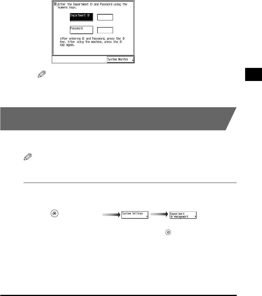
4
Setting the Department ID Management 4-21
System Manager Settings
7
Press “Done.”
Repeat this procedure.
When the screen below appears, enter the Department ID and Password.
NOTE
•
For details of how to enter the Department ID and Password, see ‘Entering the Department ID
and Password,’ on p. 1-36.
Specifying Whether or Not to Accept Print Jobs of
Unknown ID
You can specify whether or not to print documents from a computer not correspondent with a
stored Department ID.
NOTE
•“Accept jobs with unknown ID” is displayed only when the Printer Kit is attached.
•The default setting is “On.”
1
Call up the desired screen as follows:
When the System Manager ID/Password is set, enter the System Manager ID and System
Password after pressing “System Settings.” Then, press (ID).
(Additional Functions)
E1L_US_U_.book-INDEX Page 21 Wednesday, May 23, 2001 11:40 PM
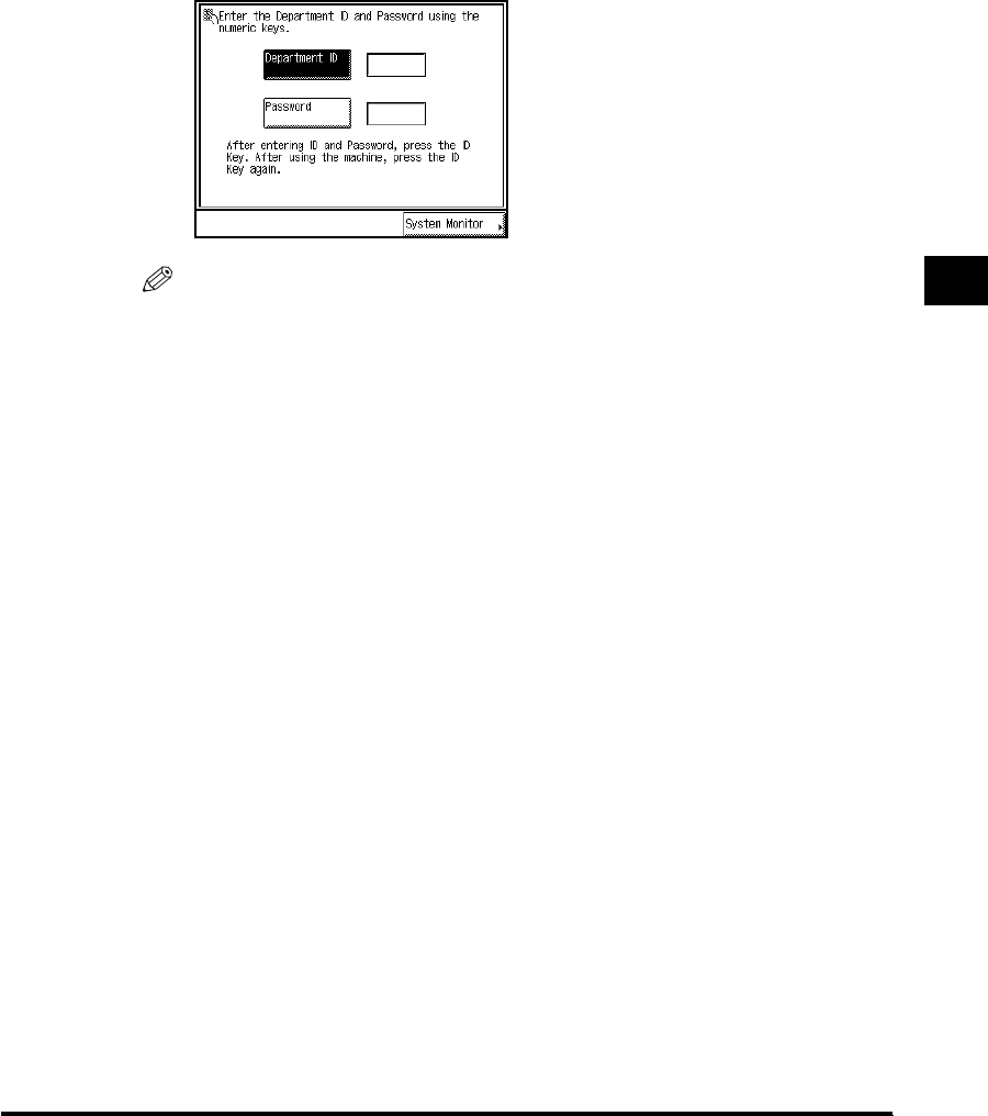
4
Setting the Department ID Management 4-23
System Manager Settings
4
Press “Done.”
Repeat this procedure.
When the screen below appears, enter the Department ID and Password.
NOTE
•
For details of how to enter the Department ID and Password, see ‘Entering the Department ID
and Password,’ on p. 1-36.
E1L_US_U_.book-INDEX Page 23 Wednesday, May 23, 2001 11:40 PM
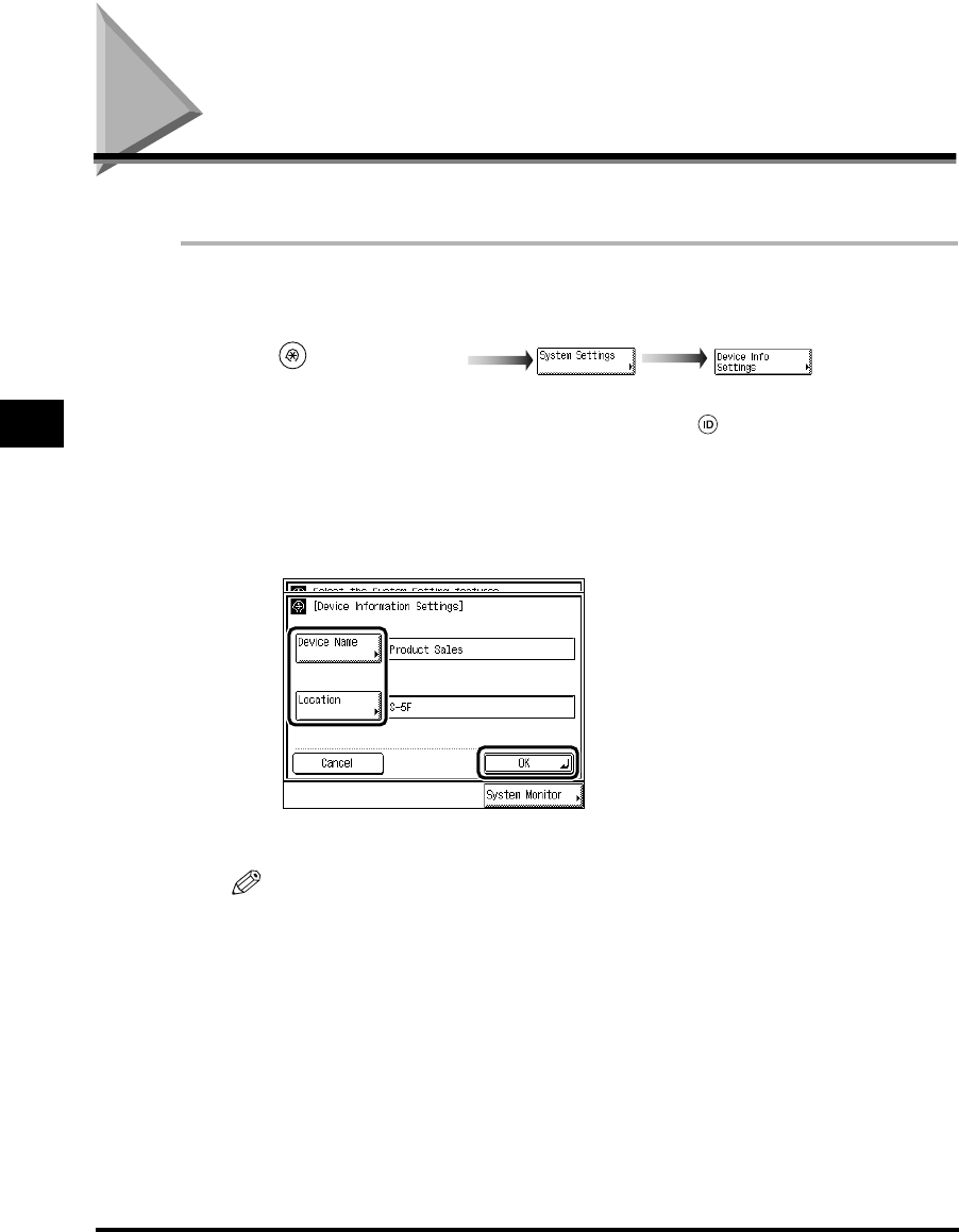
Setting Device Information (Device Information Settings)
4-24
System Manager Settings
4
Setting Device Information (Device Information Settings)
You can set a name for this machine and specify its location.
1
Call up the desired screen as follows:
When the System Manager ID/Password is set, enter the System Manager ID and System
Password after pressing “System Settings.” Then, press (ID).
2
Press “Device Name” and “Location” → enter the name of this
machine and the location where this machine is placed → press
“OK.”
The maximum number of characters which can be entered is 32.
NOTE
•
For details of how to enter characters, see ‘Entering Characters from the Touch Panel Display,’
on p. 1-31.
•
If you do not want to store the name and location, press “Cancel.”
3
Press “Done.”
Repeat this procedure.
The specified mode is set and the display returns to the Basic Features screen.
(Additional Functions)
E1L_US_U_.book-INDEX Page 24 Wednesday, May 23, 2001 11:40 PM

Erasing the Message Board (Clear Message Board) 4-25
System Manager Settings
4
Erasing the Message Board (Clear Message Board)
The “Message Board” is a function used by the system manager to display messages for
users of this machine on the touch panel display. Message board settings are done from the
Remote UI, however, erasing a message board can be done from the main unit as well.
1
Call up the desired screen as follows:
When the System Manager ID/Password is set, enter the System Manager ID and System
Password after pressing “System Settings.” Then, press (ID).
2
Select “Yes.”
If you do not want to erase the message, press “No.”
3
Press “Done.”
Repeat this procedure.
The display returns to the Basic Features screen.
(Additional Functions)
E1L_US_U_.book-INDEX Page 25 Wednesday, May 23, 2001 11:40 PM

CHAPTER
5-1
5
Routine Maintenance
This chapter describes how to load paper, add toner, and perform routine cleaning.
Loading Paper . . . . . . . . . . . . . . . . . . . . . . . . . . . . . . . . . . . . . . . . . . . . . . . . . . . . . . . . .5-2
Loading Paper in the Paper Drawers . . . . . . . . . . . . . . . . . . . . . . . . . . . . . . . . . . . . . . . . . . . . . .5-2
Adjusting a Paper Drawer to Hold a Different Paper Size . . . . . . . . . . . . . . . . . . . . . . . . . . . . . .5-6
Adding Toner. . . . . . . . . . . . . . . . . . . . . . . . . . . . . . . . . . . . . . . . . . . . . . . . . . . . . . . . . . .5-9
Routine Cleaning . . . . . . . . . . . . . . . . . . . . . . . . . . . . . . . . . . . . . . . . . . . . . . . . . . . . . .5-15
Cleaning the Platen Glass/Rear Side of Platen Glass Cover . . . . . . . . . . . . . . . . . . . . . . . . . . .5-16
Cleaning the Feeder 1 . . . . . . . . . . . . . . . . . . . . . . . . . . . . . . . . . . . . . . . . . . . . . . . . . . . . . . .5-17
Cleaning the Feeder 2 . . . . . . . . . . . . . . . . . . . . . . . . . . . . . . . . . . . . . . . . . . . . . . . . . . . . . . .5-20
Roller Cleaning . . . . . . . . . . . . . . . . . . . . . . . . . . . . . . . . . . . . . . . . . . . . . . . . . . . . . . . . . . . . . .5-21
Consumables and Options . . . . . . . . . . . . . . . . . . . . . . . . . . . . . . . . . . . . . . . . . . . . . . .5-23
Consumables . . . . . . . . . . . . . . . . . . . . . . . . . . . . . . . . . . . . . . . . . . . . . . . . . . . . . . . . . . . . . . .5-23
Options . . . . . . . . . . . . . . . . . . . . . . . . . . . . . . . . . . . . . . . . . . . . . . . . . . . . . . . . . . . . . . . . . . . .5-25
E1L_US_U_.book-INDEX Page 1 Wednesday, May 23, 2001 11:40 PM
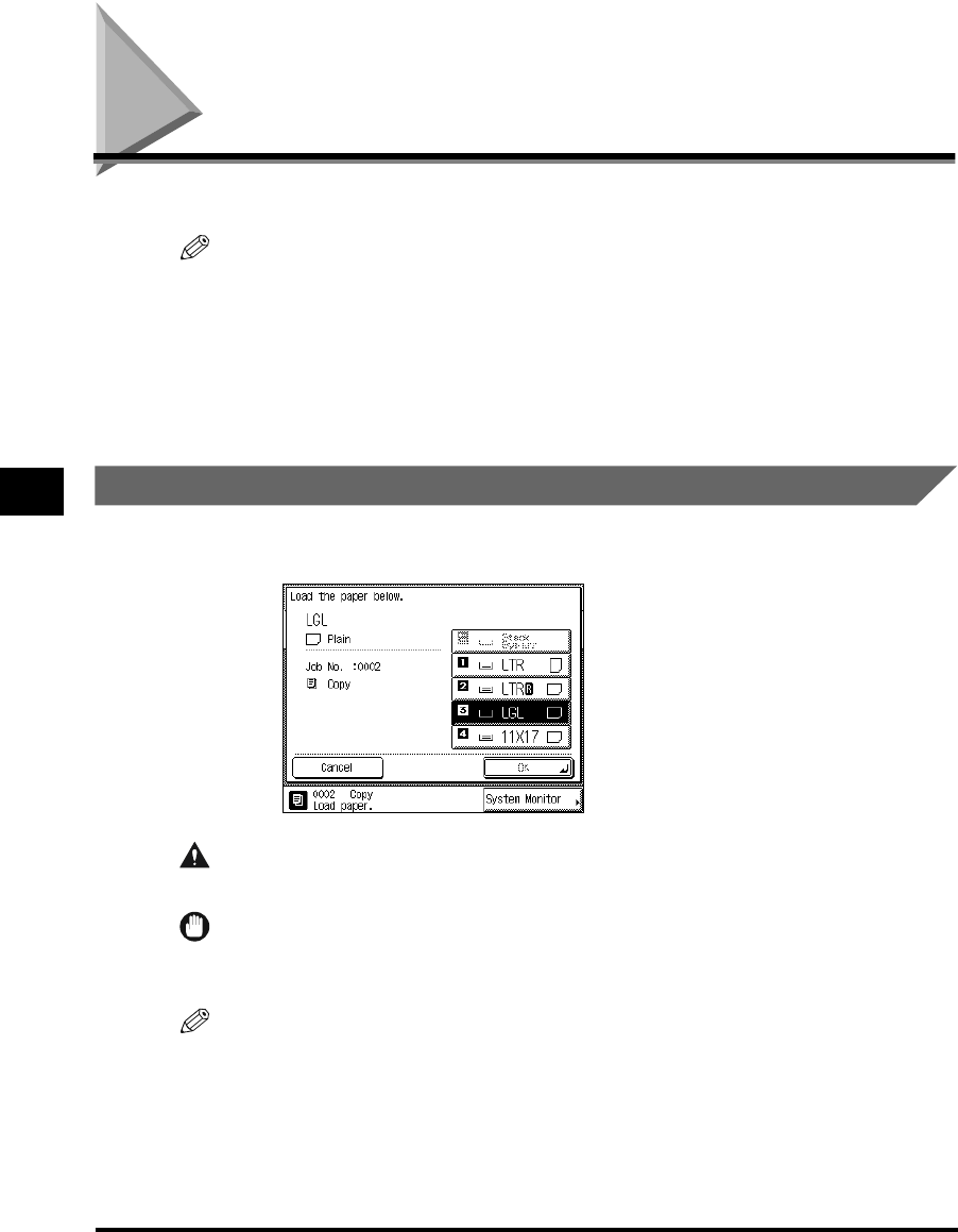
Loading Paper
5-2
Routine Maintenance
5
Loading Paper
This section describes how to load paper in the paper drawers.
NOTE
•
The following paper sizes can be loaded in the paper drawers:
-Paper drawers 1, 3: LGL, LTR, LTRR, STMT, and STMTR
-Paper drawers 2, 4: 11" x 17", LGL, LTR, LTRR, STMT, and STMTR
-Paper drawers 3 and 4 can be used when the Cassette Feeding Unit-W1 (option) is attached.
•
For details of available paper stock which can be loaded in the paper drawers, see ‘Available Paper
Stock,’ on p. 1-59.
Loading Paper in the Paper Drawers
When the selected paper has run out, or the selected paper drawer runs out of paper during
printing, a screen prompting you to load paper appears on the touch panel display.
CAUTION
•When loading paper, take care not to cut your hands on the edges of the paper.
IMPORTANT
•
The message also appears if the selected paper drawer is not fully inserted into the machine. Once
you properly insert the paper drawer, the message disappears.
NOTE
•
If the above message appears during printing, the remaining prints are automatically made after you
load the correct paper. When you select another paper drawer, the remaining prints are made after
you press “OK.”
•
To cancel printing, press “Cancel.”
E1L_US_U_.book-INDEX Page 2 Wednesday, May 23, 2001 11:40 PM

5
Loading Paper 5-3
Routine Maintenance
1
Press and release the button of the paper drawer in which you want
to load paper.
2
Grip the handle and pull out the paper drawer until it stops.
3
Open a package of paper, and remove the paper stack.
E1L_US_U_.book-INDEX Page 3 Wednesday, May 23, 2001 11:40 PM
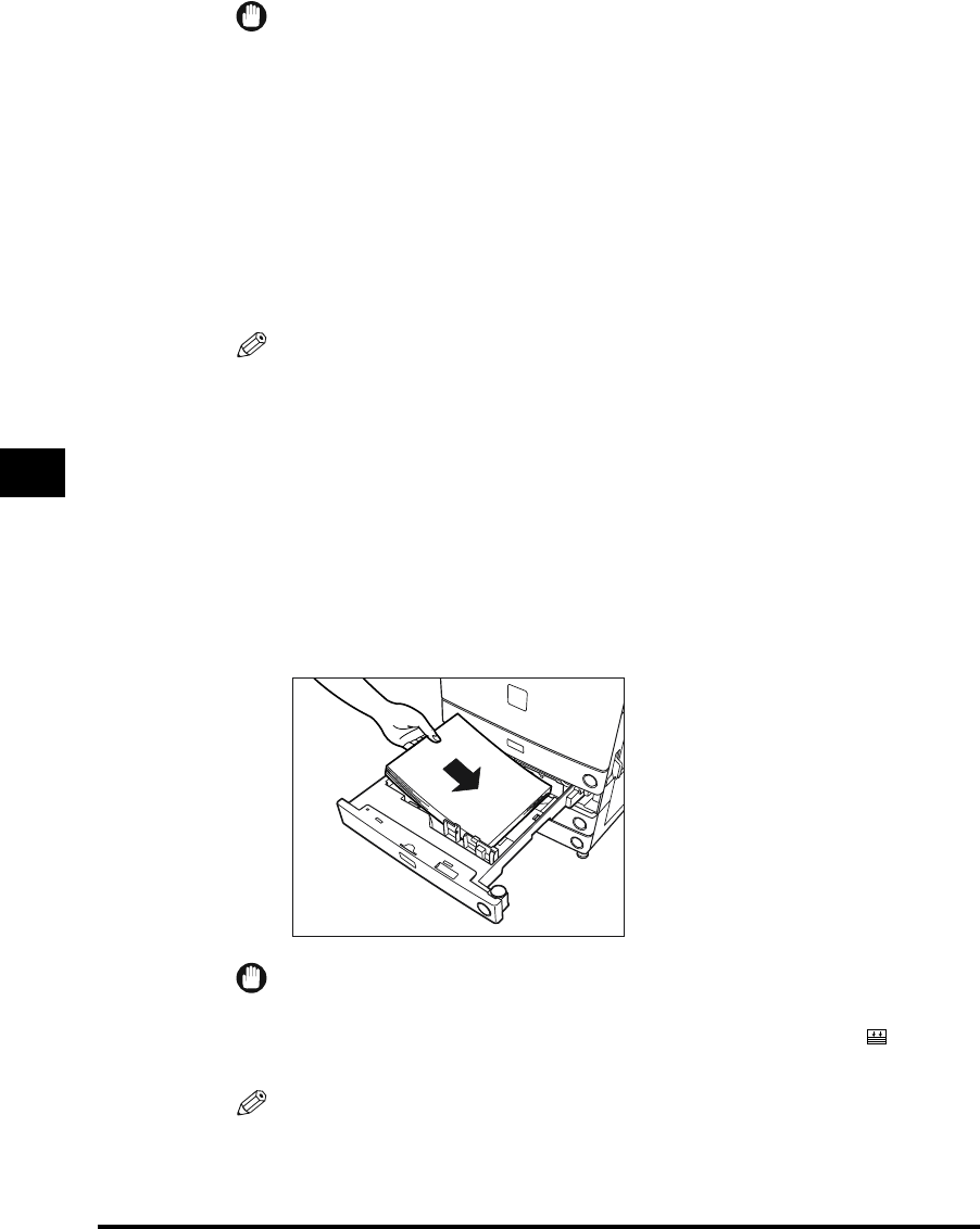
5
Loading Paper
5-4
Routine Maintenance
IMPORTANT
•
Rewrap any remaining paper in its original package, and store it in a dry place, away from
direct sunlight.
•
Do not load the following types of paper in the paper drawer. Doing so may cause a paper
jam.
-Severely curled or wrinkled paper
- Heavyweight paper
-Transparencies
-Paper on which color images have been copied.
-Paper which has been copied on using a digital full color copier (do not copy on the reverse
side either).
-Paper which has been printed on using a thermal transfer printer (do not copy on the
reverse side either).
NOTE
•
For high-quality print output, use paper recommended by Canon.
4
Turn the opened surface of the paper stack over, and place it in the
paper drawer.
Even out the edges of the paper stack. Load the paper stack against the right wall of the
paper drawer.
When loading paper in the paper drawer for the first time, set the size plate for the paper
being loaded.
When loading paper in the paper drawer, make sure that the paper size setting of the
paper drawer matches the size of paper.
IMPORTANT
•If the paper is curled, curl it down before placing it in the paper drawer.
•Make sure that the height of the paper stack does not exceed the limit mark at the back
of the paper drawer.
NOTE
•
Each paper drawer holds about 500 sheets of paper (20-lb bond (80g/m
2
)).
•For details of the print direction of paper already printed with logos or patterns, see
‘Relation of Original Orientation and Paper Orientation,’ on p. 8-9.
E1L_US_U_.book-INDEX Page 4 Wednesday, May 23, 2001 11:40 PM
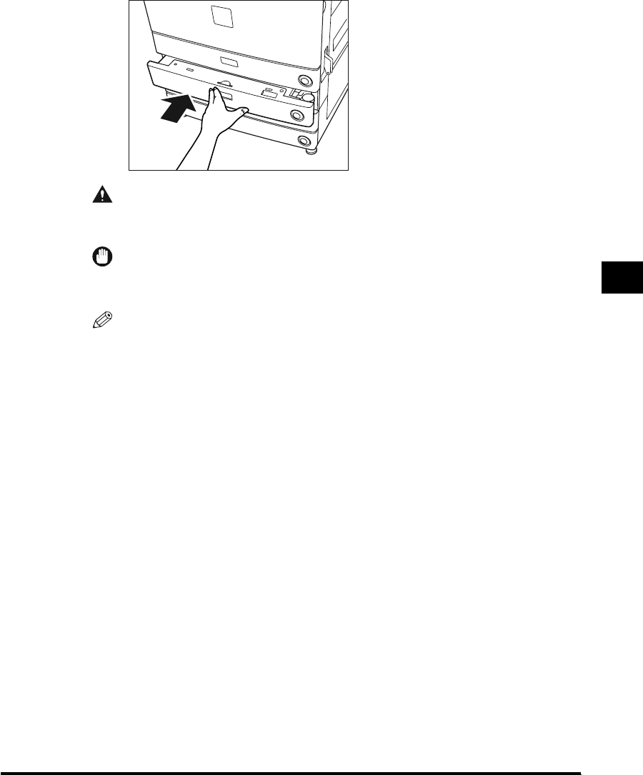
5
Loading Paper 5-5
Routine Maintenance
5
Gently push the paper drawer back into the machine until it clicks.
CAUTION
•When returning the paper drawer to its original position, be careful not to get your
fingers caught, as this may result in personal injury.
IMPORTANT
•
Never place paper or any other items in the open part of the paper drawer next to the paper
stack. Doing so may cause paper jams.
NOTE
•
When paper runs out during printing, load new paper, and follow the instructions on the touch
panel display. The machine automatically restarts and produces the remaining prints.
E1L_US_U_.book-INDEX Page 5 Wednesday, May 23, 2001 11:40 PM

5
Loading Paper 5-7
Routine Maintenance
3
Squeeze the lever on the front guide, as shown below. Without
releasing the lever, slide the front guide to align it with the mark for
the desired paper size.
IMPORTANT
•
Not adjusting the guides correctly may cause paper jams, dirty prints, or make the inside of
the machine dirty. To prevent these problems, check that the guides are adjusted correctly for
the loaded paper size.
4
Set the size switch to match the paper being loaded.
“INCH”: For Inch series paper
“A/B”: For A/B series paper
If you change the setting of the size switch, replace the label on the paper size dial,
accordingly.
IMPORTANT
•
Not setting the size switch correctly, results in the display of an incorrect paper size on the
touch panel display. Also, it may cause paper jams, dirty prints, or make the inside of the
machine dirty. To prevent these problems, check that the size switch is set correctly.
Front Guide
INCH
A/B
E1L_US_U_.book-INDEX Page 7 Wednesday, May 23, 2001 11:40 PM

5
Loading Paper
5-8
Routine Maintenance
5
Set the paper size dial, located on the right side of the paper drawer,
to match the paper being loaded.
IMPORTANT
•
Not setting the paper size dial correctly, results in the display of an incorrect paper size on the
touch panel display. Also, it may cause paper jams, dirty prints, or make the inside of the
machine dirty. To prevent these problems, check that the paper size dial is set correctly.
6
Change the paper drawer’s size plate, so that it matches the new
paper size being loaded.
STMT
R
LTR
LTR
R
LGL
11X17
U4
STMT
E1L_US_U_.book-INDEX Page 8 Wednesday, May 23, 2001 11:40 PM

Adding Toner 5-9
Routine Maintenance
5
Adding Toner
When there is only a small amount of toner remaining in the machine, the message shown
below, on the left side, appears on the touch panel display. Prints can still be made, but at
this time you should purchase new toner so that you have it on hand when it is needed.
When the toner has run out and prints can no longer be made, the message shown below,
on the right side, appears on the touch panel display. The message explains how to add
toner.
CAUTION
•Do not throw used toner cartridges into open flames, as this may ignite the toner
remaining inside the cartridge, and result in burns or a fire.
IMPORTANT
•
Use only the toner cartridge recommended for use on this machine.
•
Never add more than one toner cartridge.
•
Add toner soon after the <Add toner.> message is displayed.
NOTE
•
When the <Add toner.> message appears, approximately 300 prints can still be made (LTR-size
Canon Standard Chart). However, since this number may vary depending upon the original, it is
recommended that toner be added as soon as possible.
•
You can check how to add toner by pressing “Previous” or “Next” from the screen.
•
If the toner runs out during a print job, the remaining prints are made after you add toner.
E1L_US_U_.book-INDEX Page 9 Wednesday, May 23, 2001 11:40 PM
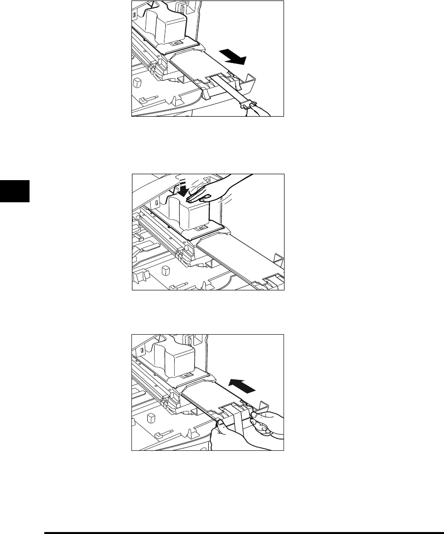
5
Adding Toner
5-12
Routine Maintenance
7
Pull the black cartridge knob, until the stop sign appears.
8
Lightly tap the top of the toner cartridge to cause the toner to empty
into the toner box.
9
Push the black toner box handle back to its original position.
The toner cartridge will be pushed in, along with the toner box.
E1L_US_U_.book-INDEX Page 12 Wednesday, May 23, 2001 11:40 PM
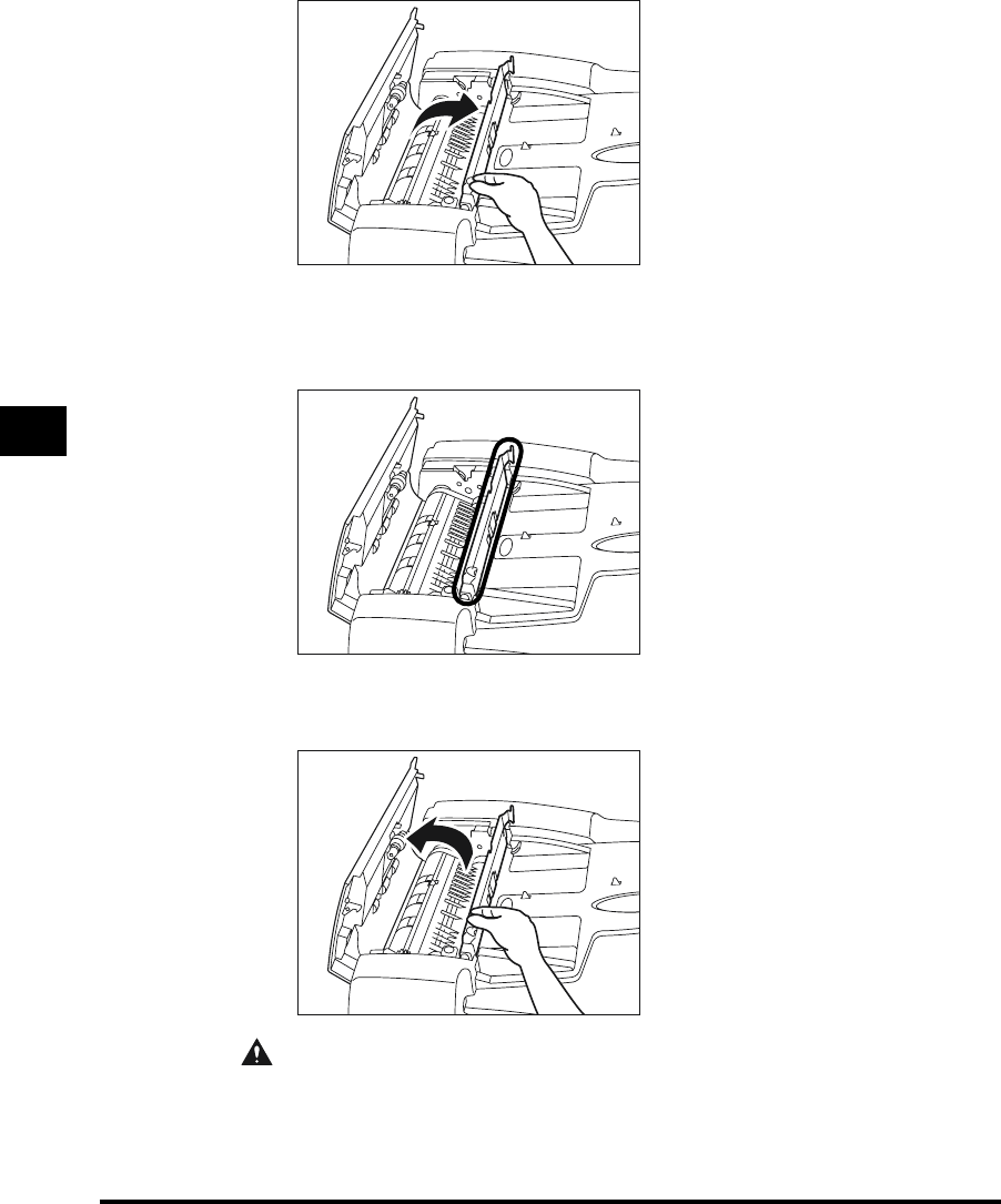
5
Routine Cleaning
5-18
Routine Maintenance
3
Open the middle cover, holding the knob in the front.
4
Clean the transparent plastic part of the middle cover with a cloth
dampened with water.
5
Close the middle cover.
CAUTION
•When closing the cover, be careful not to get your fingers caught, as this may result
in personal injury.
E1L_US_U_.book-INDEX Page 18 Wednesday, May 23, 2001 11:40 PM

5
Routine Cleaning 5-19
Routine Maintenance
6
Close the feeder cover.
CAUTION
•When closing the cover, be careful not to get your fingers caught, as this may result
in personal injury.
7
Open the feeder.
8
Clean the feeder scanning area (platen glass) and the metal part
located next to the rubber roller, with a cloth dampened with water.
E1L_US_U_.book-INDEX Page 19 Wednesday, May 23, 2001 11:40 PM
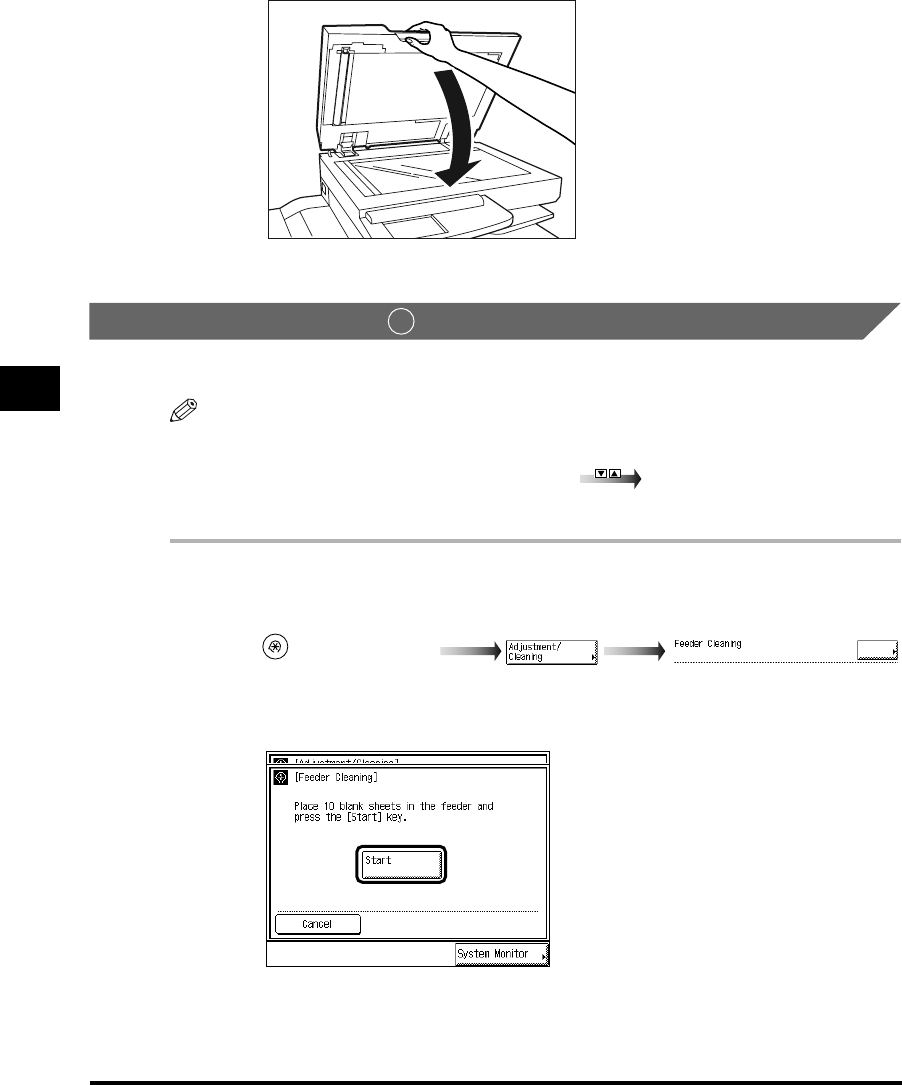
5
Routine Cleaning
5-20
Routine Maintenance
9
Close the feeder.
Cleaning the Feeder
You can also clean the roller by repeatedly feeding blank paper sheets through the feeder.
NOTE
•
“Adjustment/Cleaning” is made up of several screens. Select the desired item by pressing “
▼
” or
“
▲
.”
•
When “
▼
” or “
▲
” shoud be pressed, the indications is displayed in this manual.
•It takes about 20 seconds to clean the feeder.
1
Call up the desired screen as follows:
2
Place 10 blank paper sheets in the feeder, and press “Start.”
To cancel the feeder cleaning, press “Cancel.”
2
(Additional Functions)
E1L_US_U_.book-INDEX Page 20 Wednesday, May 23, 2001 11:40 PM

5
Consumables and Options
5-24
Routine Maintenance
■Black Toner
When the <Add toner.> message appears on the touch panel display, add toner which has
been approved for use with this machine.
WARNING
•Never dispose of waste toner in a fire or incinerator. Doing so may result in an explosion.
CAUTION
•Do not store toner cartridges in places exposed to open flames, as this may cause the
toner to ignite and result in burns or a fire.
IMPORTANT
•
Store toner cartridges in a cool location, away from direct sunlight.
- The recommended storage conditions are: temperature below 86°F, and humidity below 80%.
■Genuine Supplies
Canon has developed and manufactured parts, supplies, and GPR-6 Toner specifically for
use in this machine. For superior print quality, we recommend that you use Canon-
GENUINE brand parts, supplies, and GPR-6 Toner in this machine. Ask your authorized
Canon dealer or service provider for Canon-GENUINE brand parts, supplies, and GPR-6
Toner.
E1L_US_U_.book-INDEX Page 24 Wednesday, May 23, 2001 11:40 PM

6
Clearing Paper Jams
6-6
Troubleshooting
3
After you have cleared all paper jams at the locations indicated on
the touch panel display, restore all levers and covers to their original
positions.
4
Continue operations, following the instructions displayed on the
touch panel display.
Once you have cleared the paper jam in locations other than the feeder, the print operation
restarts.
If there is remaining paper to be removed, a screen indicating how to clear that paper jam
appears on the touch panel display. Repeat the procedure from step 1.
Clearing Paper Jams in the Main Unit
If a paper jam occurs in the main unit, a screen similar to the one shown below appears on
the touch panel display. Check where the jam occurred, and follow the procedure described
below and the procedure that appears on the touch panel display, to remove the jammed
paper.
1
Open the front cover of the main unit.
E1L_US_U_.book-INDEX Page 6 Wednesday, May 23, 2001 11:40 PM

6
Clearing Paper Jams 6-7
Troubleshooting
2
Move the green lever in the direction of the arrow.
3
Remove any paper remaining in the fixing unit.
4
Turn the green knob (2 places) in the direction of the arrow, and
remove any jammed paper.
CAUTION
•The parts located around the knob are subject to high temperatures. When
removing jammed paper, take care not to touch anything in this area except the
green knob.
E1L_US_U_.book-INDEX Page 7 Wednesday, May 23, 2001 11:40 PM
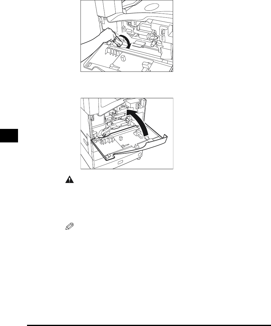
6
Clearing Paper Jams
6-8
Troubleshooting
5
Return the green lever to its original position.
6
Close the front cover of the main unit.
CAUTION
•When closing the cover, be careful not to get your fingers caught, as this may result
in personal injury.
7
Follow the instructions on the touch panel display.
NOTE
•
For details, see ‘Screen Shown When There Is a Paper Jam,’ on p. 6-2.
E1L_US_U_.book-INDEX Page 8 Wednesday, May 23, 2001 11:40 PM

6
Clearing Paper Jams 6-9
Troubleshooting
Clearing Paper Jams in the Duplexing Unit
If a paper jam occurs in the duplexing unit, a screen similar to the one shown below appears
on the touch panel display. Check where the jam occurred, and follow the procedure
described below and the procedure that appears on the touch panel display, to remove the
jammed paper.
1
Open the front cover of the main unit.
2
Lift the green lever of the duplexing unit with one hand, and pull out
the jammed paper with the other hand.
E1L_US_U_.book-INDEX Page 9 Wednesday, May 23, 2001 11:40 PM
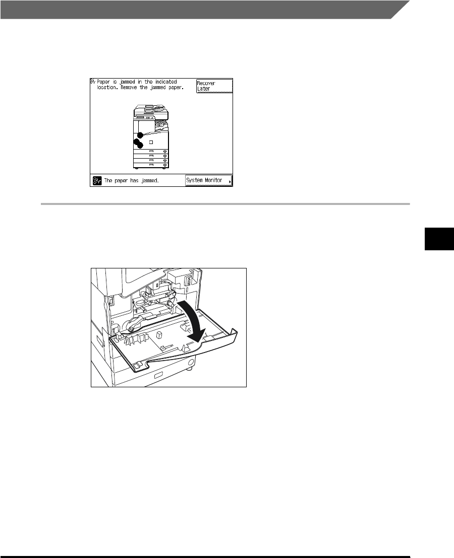
6
Clearing Paper Jams 6-11
Troubleshooting
Clearing Paper Jams in the Exit Slot
If a paper jam occurs in the exit slot, a screen similar to the one shown below appears on the
touch panel display. Check where the jam occurred, and follow the procedure described
below and the procedure that appears in the touch panel display, to remove the jammed
paper.
1
Open the front cover of the main unit.
When the Saddle Finisher-G1 (option; see p. 7-47) is attached, move the finisher away from
the main unit.
E1L_US_U_.book-INDEX Page 11 Wednesday, May 23, 2001 11:40 PM

6
Clearing Paper Jams
6-12
Troubleshooting
2
Move the green lever in the direction of the arrow.
3
Open the lower left cover of the main unit.
4
Lift the green lever and remove any jammed paper.
CAUTION
•The parts located around the green lever of the exit slot guide are subject to high
temperatures. When removing jammed paper, take care not to touch anything in this
area except the lever.
E1L_US_U_.book-INDEX Page 12 Wednesday, May 23, 2001 11:40 PM
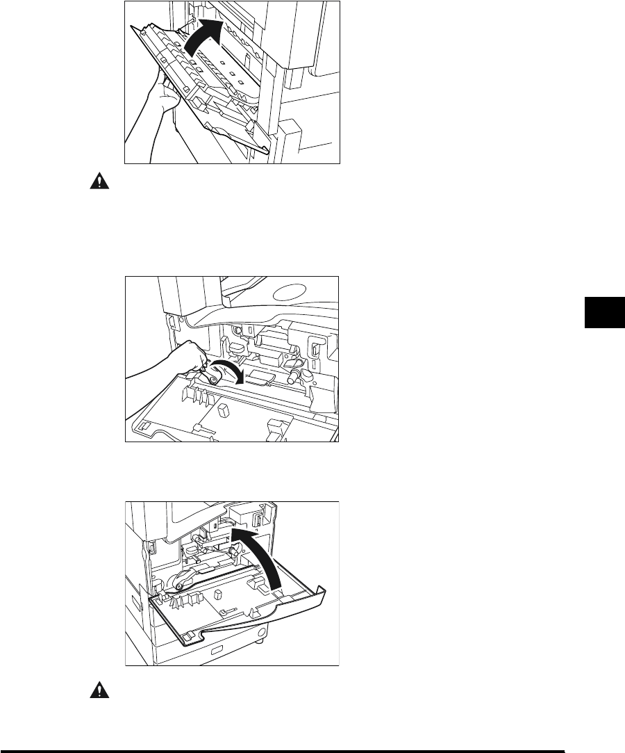
6
Clearing Paper Jams 6-13
Troubleshooting
5
Close the lower left cover.
CAUTION
•When closing the cover, be careful not to get your fingers caught, as this may result
in personal injury.
6
Return the green lever to its original position.
7
Close the front cover.
CAUTION
•When closing the cover, be careful not to get your fingers caught, as this may result
in personal injury.
E1L_US_U_.book-INDEX Page 13 Wednesday, May 23, 2001 11:40 PM

6
Clearing Paper Jams
6-16
Troubleshooting
Clearing Paper Jams in the Stack Bypass
If a paper jam occurs in the stack bypass, a screen similar to the one shown below appears
on the touch panel display. Check where the jam occurred, and follow the procedure
described below and the procedure that appears on the touch panel display, to remove the
jammed paper.
1
Remove all paper from the stack bypass.
2
Remove any jammed paper.
E1L_US_U_.book-INDEX Page 16 Wednesday, May 23, 2001 11:40 PM
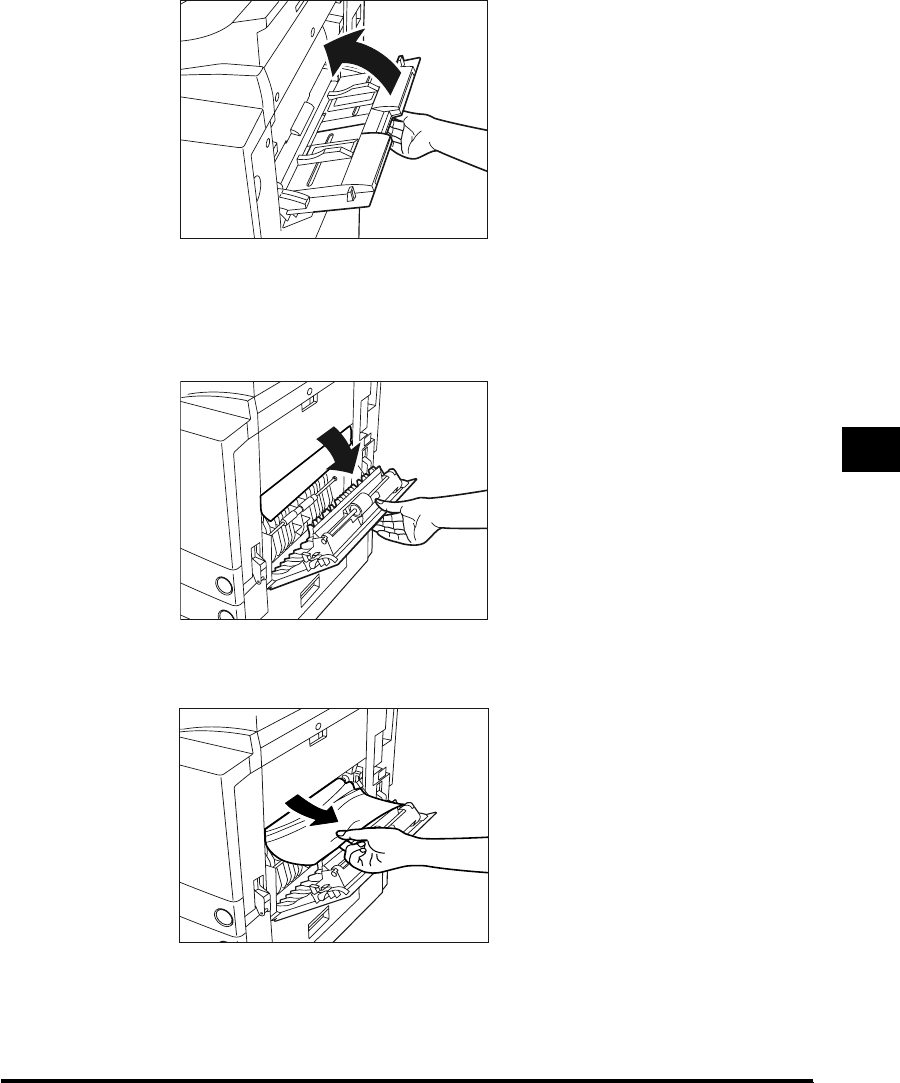

6
Clearing Paper Jams
6-18
Troubleshooting
6
Close the upper right cover of the main unit.
When the Paper Deck-L1 (option; see p. 7-9) is attached, reattach the paper deck to the
main unit.
CAUTION
•When closing the cover, be careful not to get your fingers caught, as this may result
in personal injury.
7
Follow the instructions on the touch panel display.
NOTE
•
For details of the screen indicating how to clear the paper jam, see ‘Screen Shown When
There Is a Paper Jam,’ on p. 6-2.
E1L_US_U_.book-INDEX Page 18 Wednesday, May 23, 2001 11:40 PM
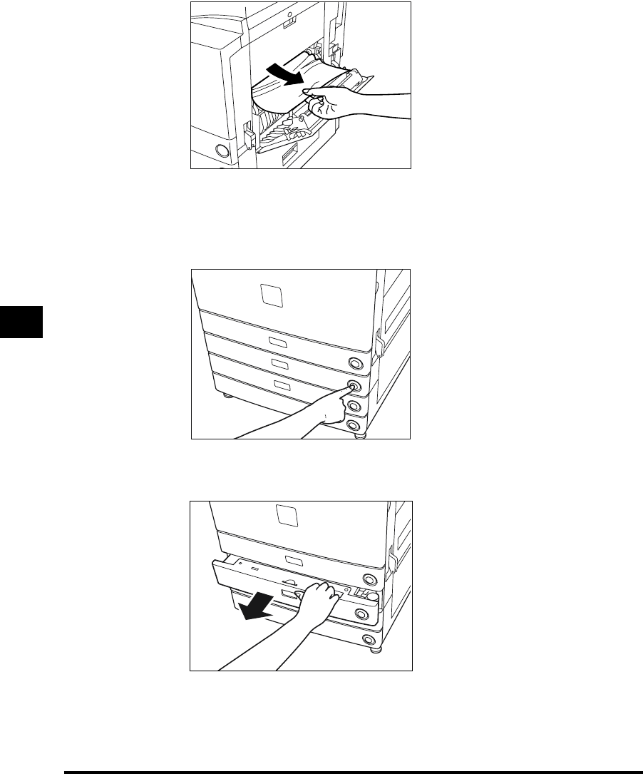
6
Clearing Paper Jams
6-20
Troubleshooting
2
Remove any jammed paper.
3
Press and release the paper drawer release button of the paper
drawer indicated on the touch panel display, until the paper drawer
releases.
4
Pull out the paper drawer.
E1L_US_U_.book-INDEX Page 20 Wednesday, May 23, 2001 11:40 PM
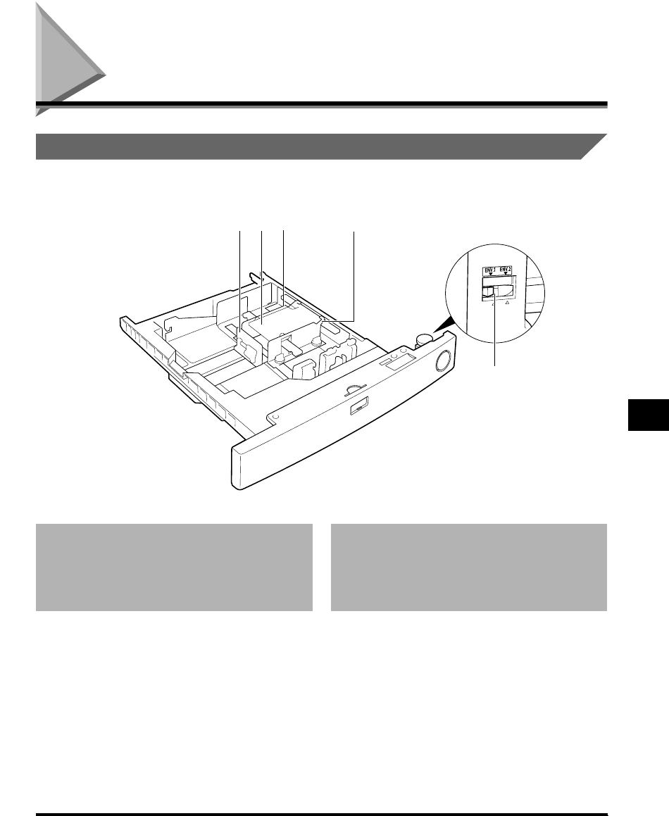
Envelope Feeder Attachment-B1 7-15
Handling Options
7
Envelope Feeder Attachment-B1
Parts and Their Functions
When the Envelope Feeder Attachment is attached to Paper Drawer 1:
1 Left guide
Align to the length of envelopes being loaded.
2 Envelope receptacle
3 Back width guide
4 Front width guide
5 Size switch
Select either “ENV.1” or “ENV.2” for the envelope
cassette.
123
5
4
E1L_US_U_.book-INDEX Page 15 Wednesday, May 23, 2001 11:40 PM

7
Envelope Feeder Attachment-B1
7-20
Handling Options
2
Grip the handle and pull out the paper drawer until it stops.
3
Squeeze the lever on the left guide, as shown below, and pull out the
left guide as far as possible.
4
Load the envelopes with the printing surface face down, as shown
below. While doing so, keep the receptacle pressed down by
pressing down on the envelopes as you load them.
E1L_US_U_.book-INDEX Page 20 Wednesday, May 23, 2001 11:40 PM

7
Envelope Feeder Attachment-B1 7-25
Handling Options
5
Pull out the left guide, and remove all envelopes already loaded in
the drawer.
6
Loosen the two screws fixing the front width guide of the cassette.
7
As shown below, push down on the envelope receptacle, and move
the front width guide so that they are aligned with the mark for the
desired type of envelope.
E1L_US_U_.book-INDEX Page 25 Wednesday, May 23, 2001 11:40 PM

7
Feeder (DADF-H1)
7-30
Handling Options
5
Close the middle cover.
CAUTION
•When closing the cover, be careful not to get your fingers caught, as this may result
in personal injury.
1111
6
Once you have removed all of the jammed original, close the upper
cover of the feeder.
CAUTION
•When closing the cover, be careful not to get your fingers caught, as this may result
in personal injury.
E1L_US_U_.book-INDEX Page 30 Wednesday, May 23, 2001 11:40 PM

7
Finisher-J1 7-41
Handling Options
2
Pull out the staple cartridge, holding it by its left and right sides.
3
Pull out the empty staple case, holding it by its left and right sides.
Place the staple cartridge, as shown below, and pull out the staple case.
E1L_US_U_.book-INDEX Page 41 Wednesday, May 23, 2001 11:40 PM
Produktspecifikationer
| Varumärke: | Canon |
| Kategori: | Kopieringsmaskin |
| Modell: | IR2200 |
| Färg på produkten: | Black, Grey |
| Vikt: | - g |
| Typ av dammsugare: | Stofzak |
| Batteri/Batterispänning: | 14.4 V |
| Form: | Rond |
| HEPA filtersystem: | Nee |
Behöver du hjälp?
Om du behöver hjälp med Canon IR2200 ställ en fråga nedan och andra användare kommer att svara dig
Kopieringsmaskin Canon Manualer

24 Augusti 2024
13 Augusti 2024
21 Juli 2024
Kopieringsmaskin Manualer
- Kopieringsmaskin HP
- Kopieringsmaskin Panasonic
- Kopieringsmaskin Xerox
- Kopieringsmaskin Brother
- Kopieringsmaskin Sharp
- Kopieringsmaskin Ricoh
- Kopieringsmaskin Olivetti
- Kopieringsmaskin Kyocera
Nyaste Kopieringsmaskin Manualer
20 Oktober 2024
17 September 2024
16 September 2024
13 September 2024
11 September 2024
8 September 2024
7 September 2024
27 Augusti 2024
26 Augusti 2024

24 Augusti 2024