CyberPower PDU41007 Bruksanvisning
CyberPower
Växla
PDU41007
Läs nedan 📖 manual på svenska för CyberPower PDU41007 (124 sidor) i kategorin Växla. Denna guide var användbar för 16 personer och betygsatt med 4.5 stjärnor i genomsnitt av 2 användare
Sida 1/124
PDU31xxx
PDU41xxx
PDU71xxx
PDU81xxx
Intelligent PDU User Guide
Copyright © 20 Cyber Power Systems, Inc. All rights reserved. 20
K01-E000003-04

I
Table of Contents
Intelligent PDU User Guide
Table of Contents
Web Interface ..............................................................................................................................1
Introduction ............................................................................................................................... 1
Advanced Power Management ............................................................................................... 10
Outlet Management ................................................................................................................ 38
Security ................................................................................................................................... 56
Network Service ...................................................................................................................... 67
PDU Information ..................................................................................................................... 79
Command Line Interface ....................................................................................................... 81
Introduction ............................................................................................................................. 81
Command Lists ....................................................................................................................... 83
Save and Restore Configuration Settings ........................................................................ 107
PDU Network Daisy Chain ................................................................................................... 109
Firmware Upgrade ................................................................................................................. 113
1
Web Interface
Intelligent PDU User Guide
Web Interface
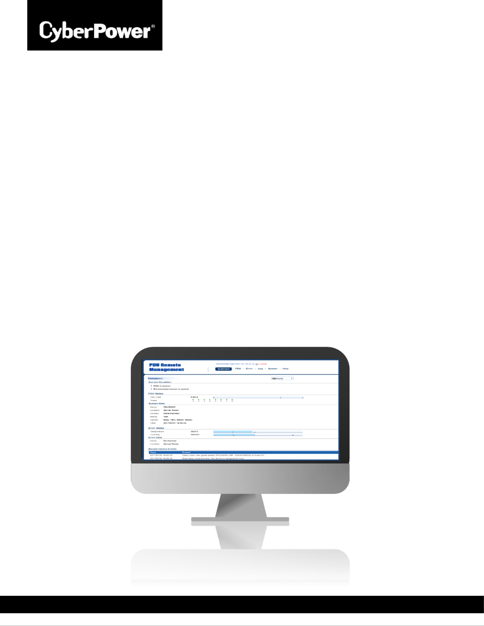
Introduction
CyberPower Intelligent Power Distribution Unit (PDU) Web Interface gives users all the features ’s
they need to congure, manage, and monitor the Intelligent PDU Series via a Web browser. With
this easy- -navigate interface, users can perform real-time monitoring of each outlet control to ,
individual outlet set power alerts, complete many other tasks in intuitive manner. , and an
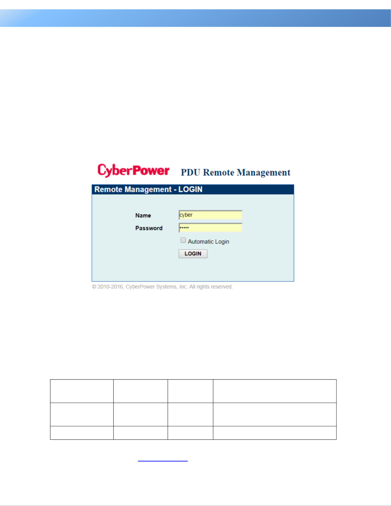
How to L in og
1. Open a Web browser.
2. Enter the IP address of the CyberPower PDU in the Browser Address Bar, and then press
ENTER.
Note: To look up the IP address, please refer to the LCD screen of the PDU.
3. and Enter the information for the User Name Password elds.
There are two types of user accounts.
Account Type
Default User
Name
Default
Password
Authorization
Administrator
cyber
cyber
View, access, and control all
settings.
Viewer
device
cyber
View all settings.
4. Click LOGIN to open the Summary Tab.
Produktspecifikationer
| Varumärke: | CyberPower |
| Kategori: | Växla |
| Modell: | PDU41007 |
Behöver du hjälp?
Om du behöver hjälp med CyberPower PDU41007 ställ en fråga nedan och andra användare kommer att svara dig
Växla CyberPower Manualer

29 Januari 2025
22 September 2024
2 September 2024
30 Augusti 2024
27 Augusti 2024
21 Augusti 2024
17 Augusti 2024
15 Augusti 2024
14 Augusti 2024
Växla Manualer
- Växla Bosch
- Växla IKEA
- Växla Huawei
- Växla HP
- Växla Philips
- Växla Panasonic
- Växla Honeywell
- Växla Yamaha
- Växla Abus
- Växla Alcatel
- Växla Alecto
- Växla Apc
- Växla Ansmann
- Växla Airlive
- Växla Edimax
- Växla Intermatic
- Växla Flamingo
- Växla Brennenstuhl
- Växla Hikvision
- Växla Generac
- Växla Silvercrest
- Växla Nedis
- Växla Pyle
- Växla Eminent
- Växla Renkforce
- Växla Vivanco
- Växla TP Link
- Växla Manhattan
- Växla Worx
- Växla Black Box
- Växla Elro
- Växla EMOS
- Växla Victron Energy
- Växla KlikaanKlikuit
- Växla Ei Electronics
- Växla Tripp Lite
- Växla DataVideo
- Växla Schneider
- Växla Hama
- Växla Theben
- Växla Elektrobock
- Växla Chamberlain
- Växla Sylvania
- Växla Velleman
- Växla Tork
- Växla Techly
- Växla Sonance
- Växla Emerson
- Växla Totolink
- Växla Vemer
- Växla Smartwares
- Växla Profile
- Växla Cisco
- Växla Matrox
- Växla Steren
- Växla Perel
- Växla Engenius
- Växla IFM
- Växla Digitus
- Växla Kathrein
- Växla AV:link
- Växla Belkin
- Växla Linksys
- Växla Buffalo
- Växla Dahua Technology
- Växla Audiovox
- Växla Cotech
- Växla Netgear
- Växla LevelOne
- Växla Kaiser
- Växla QNAP
- Växla Trotec
- Växla Boss
- Växla PreSonus
- Växla Shimano
- Växla Merten
- Växla Goobay
- Växla Hager
- Växla Mercusys
- Växla Chacon
- Växla Elation
- Växla Sygonix
- Växla Planet
- Växla ZyXEL
- Växla Rex
- Växla Powerfix
- Växla Konig
- Växla Tesla
- Växla D-Link
- Växla Tenda
- Växla UPM
- Växla One For All
- Växla Finder
- Växla Fantini Cosmi
- Växla Audac
- Växla Marmitek
- Växla Delta Dore
- Växla DoorBird
- Växla Ubiquiti Networks
- Växla EBERLE
- Växla Grasslin
- Växla Omnitronic
- Växla Eaton
- Växla Jung
- Växla Vacmaster
- Växla Basetech
- Växla Trendnet
- Växla Mikrotik
- Växla WHALE
- Växla ATen
- Växla Fibaro
- Växla RGBlink
- Växla Gefen
- Växla Nexa
- Växla PAC
- Växla Wentronic
- Växla Dormakaba
- Växla Adder
- Växla Wago
- Växla Homematic IP
- Växla Monoprice
- Växla Tiptel
- Växla OSD Audio
- Växla SPC
- Växla Crestron
- Växla Unify
- Växla ORNO
- Växla Toolcraft
- Växla Berker
- Växla Electro Harmonix
- Växla Grandstream
- Växla Mercury
- Växla Provision ISR
- Växla Monacor
- Växla PCE
- Växla Logilink
- Växla Smart-AVI
- Växla StarTech.com
- Växla SIIG
- Växla Advantech
- Växla IOGEAR
- Växla Merlin Gerin
- Växla Micro Connect
- Växla Extron
- Växla KanexPro
- Växla Blustream
- Växla Avocent
- Växla Shelly
- Växla Intellinet
- Växla Ebode
- Växla Lancom
- Växla Robbe
- Växla ICasa
- Växla B-tech
- Växla Speaka
- Växla Kopp
- Växla Vimar
- Växla Kemo
- Växla GAO
- Växla H-Tronic
- Växla Legrand
- Växla Kraus & Naimer
- Växla Noble
- Växla Intertechno
- Växla Ecler
- Växla Inverto
- Växla Triax
- Växla Rule
- Växla Kramer
- Växla CYP
- Växla Suevia
- Växla Phoenix Contact
- Växla Seuthe
- Växla Maclean Energy
- Växla SmartAVI
- Växla Leviton
- Växla DEHN
- Växla Cudy
- Växla Brilliant
- Växla Heitronic
- Växla Lindy
- Växla SEC24
- Växla Cooking Performance Group
- Växla Ernitec
- Växla Atlona
- Växla Adviti
- Växla Flic
- Växla HELGI
- Växla IB Connect
- Växla Liberty
- Växla PureTools
- Växla Hamlet
- Växla Paladin
- Växla Equip
- Växla Noark
- Växla Vivolink
- Växla Alfatron
- Växla Cambium Networks
- Växla 2USB
- Växla Roline
- Växla KVM-TEC
- Växla AMX
- Växla BZBGear
- Växla STI
- Växla Epiphan
- Växla Ebara
- Växla Mach Power
- Växla Axing
- Växla Juniper
- Växla Raritan
- Växla ConnectPro
- Växla SunBriteTV
- Växla Atlantis Land
- Växla GEV
- Växla Pizzato Elettrica
- Växla Baco
- Växla SEADA
- Växla Doepke
- Växla Comet
- Växla IPGARD
- Växla CSL
- Växla Setti+
- Växla PureLink
- Växla INOGENI
- Växla Luxul
Nyaste Växla Manualer
1 April 2025
1 April 2025
1 April 2025
1 April 2025
1 April 2025
1 April 2025
1 April 2025
1 April 2025
1 April 2025
31 Mars 2025