Marmitek DoorPhone 210 Bruksanvisning
Marmitek
Intercomsystem
DoorPhone 210
Läs nedan 📖 manual på svenska för Marmitek DoorPhone 210 (124 sidor) i kategorin Intercomsystem. Denna guide var användbar för 6 personer och betygsatt med 4.5 stjärnor i genomsnitt av 2 användare
Sida 1/124

VIDEO
DOORPHON
20650/20160830 • VIDEO DOORPHONE 210™
ALL RIGHTS RESERVED MARMITEK ©
VIDEO
DOORPHONE 210
™
USER MANUAL 3
GEBRAUCHSANLEITUNG 21
GUIDE UTILISATEUR 41
MODO DE EMPLEO 61
MANUALE D’ISTRUZIONI 81
GEBRUIKSAANWIJZING 101

© MARMITEK
2

Video DoorPhone 210
3
ENGLISH
1 Safety warnings
x Do not expose the components of your system to extremely high
temperatures or bright light sources.
x Improper use, self-installed modifications or repairs will void any and
all warranties. Marmitek does not accept any product responsibility
for incorrect use of the product or use other than for which the
product is intended. Marmitek does not accept liability for any
consequential damage other than the legal product responsibility.
x This product is not a toy. Keep out of reach of children.
x Do not open the product (battery panel is an exception): the device
may contain live parts. The product should only be repaired or
serviced by a qualified expert.
x Keep batteries out of the reach of children. Dispose of batteries as
chemical waste. Never use old and new batteries or different types of
batteries together. Remove the batteries when you are not using the
system for a longer period of time. Check the polarity (+/-) of the
batteries when inserting them in the product. Wrong positioning can
cause an explosion.
x Only connect the adapter to the mains after checking whether the
mains voltage is the same as the values on the identification tags.
Never connect an adapter or power cord when it is damaged. In that
case, contact your supplier.
x Disconnect the AC/DC power adapter from the mains when this
device is not in use for prolonged time.

© MARMITEK
4
2 Table of contents
1 Safety warnings ................................................................................. 3
2 Table of contents ............................................................................... 4
3 Introduction ........................................................................................ 5
4 Features ............................................................................................ 5
5 Set contents ....................................................................................... 5
6 Controls layout ................................................................................... 6
7 Getting started ................................................................................... 7
7.1 Power Supply .......................................................................... 7
7.1.1 Door unit ............................................................................. 7
7.1.2 Backup ................................................................................ 7
7.1.3 Handset .............................................................................. 8
7.2 Pairing the handset and the door unit ...................................... 9
7.3 Mounting of door Unit ............................................................ 10
7.3.1 Always close ..................................................................... 10
7.3.2 Always open ...................................................................... 10
7.3.3 Auxiliary terminal ............................................................... 11
8 Operation ......................................................................................... 11
8.1 ON / OFF ............................................................................... 11
9 Caller setting .................................................................................... 12
9.1 Gate ...................................................................................... 12
9.2 Volume .................................................................................. 12
9.3 Brightness ............................................................................. 12
9.4 Contrast ................................................................................. 13
9.5 Gate light ............................................................................... 13
9.6 Alarm mode ........................................................................... 13
9.7 Door lock open ...................................................................... 13
9.8 Trigger time ........................................................................... 13
9.9 Date/time ............................................................................... 14
9.10 Exit ........................................................................................ 14
9.11 Missed call(s) ........................................................................ 17
9.12 Precaution ............................................................................. 17
10 Frequently asked questions ......................................................... 18
11 Technical data .............................................................................. 19
12 Copyrights .................................................................................... 20

Video DoorPhone 210
5
ENGLISH
3 Introduction
Congratulations on your purchase of the Marmitek Video DoorPhone 210.
Your Video DoorPhone 210 has been manufactured and checked under
the strictest possible quality control to ensure that each Video DoorPhone
210 leaves the factory in perfect condition. In the unlikely event you find
any defect or experience any problem, please contact our service centre
or dealer, do not attempt to repair by yourself.
Please read this manual carefully to obtain optimum performance and
extended service life from the system.
4 Features
x Mobile wireless video doorphone system.
x Always see who's at the door before you open it, from anywhere in
your home.
x Get a good view of people day and night, with a digitally adjustable
camera angle, zoom feature and LED lighting.
x Interference-free coverage, anywhere in your home.
x Easy installation, using existing wiring.
x Including missed call notification and automatic image storage of last
10 visitors.
x Rugged, weatherproof housing.
x Open the door remotely by electric door opener (optional).
x Selectable doorbell warning: audio, visual and/or vibrate.
x Digital transmission - ensures interference-free calls.
5 Set contents
a. Handset
b. Door Unit
c. Charger stand
d. Switching power
supply for
charger stand
e. Rechargeable Li
battery pack
(installed in
handset)
f. Tool
g. Screws and rivets
h. Manual
© MARMITEK
6
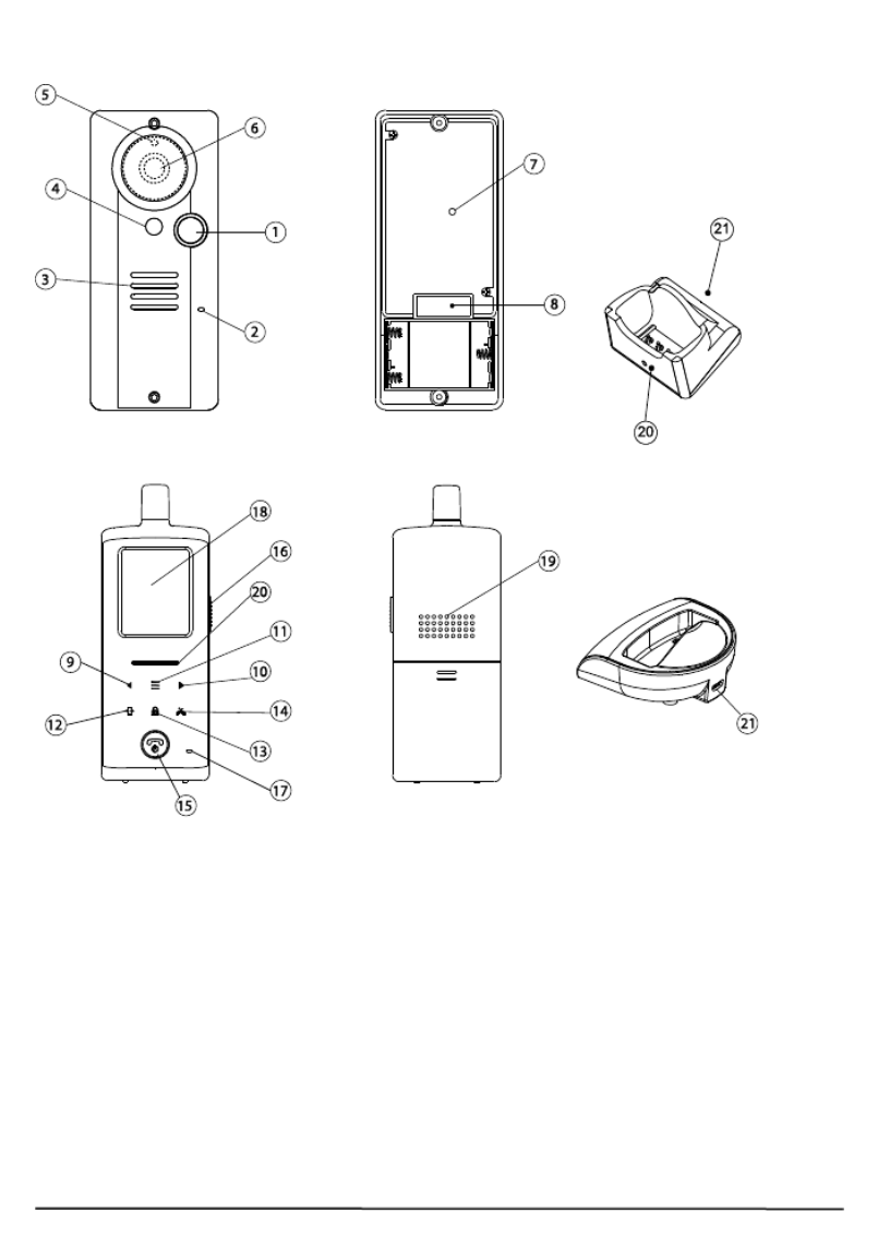
6 Controls layout
Handset unit
1. Call button
2. Microphone
3. Speaker
4. White illumination LED
5. Light sensor
6. Camera lens
7. Pairing button
8. Terminal block
9. Volume down/Left key
10. Volume up/Right key
11. Menu key
12. Image shift key
13. Door lock open key
14. Missed calls key
15. Hang up and power ON/OFF button
16. Talk and answer button
17. Microphone
18. TFT screen
19. Speaker
20. Power and battery low indicator
21. USB port
Charging stand
Door unit

Video DoorPhone 210
7
ENGLISH
7 Getting started
7.1 Power Supply
7.1.1 Door unit
With the supplied tool, loosen the screws holding the unit from the
mounting bracket. The screws are made specifically for anti-theft
purposes. It is necessary to keep the tool in a safe place for when you
need it later when replacing batteries. The door unit is powered with 8 to
12V AC or 12V DC. Connect a power supply to the terminals (8) at the
back marked with (not included).
In case of a power failure, the unit will automatically switch to power from
the alkaline batteries (if installed).
You can use your existing doorbell transformer as power supply, as long
as it can provide 8…12V, AC or 12V DC. When you want to use another
12V power supply, make sure it has a stable voltage output (Switching
adapter 100-240VAC (V) 12VDC) and not a transformer type that has a
high no load voltage!
7.1.2 Backup
Insert three UM-4 size AAA alkaline cells into the battery compartment;
observe correct polarity. We strongly recommend using alkaline batteries
instead of rechargeable batteries because at low temperatures (below
0˚C), rechargeable ones have poor performance and their capacity will
fall.
Please note the alkaline batteries are used only as a backup in case of
mains failure. They can only last for 1 - 2 days under normal operation.
© MARMITEK
8
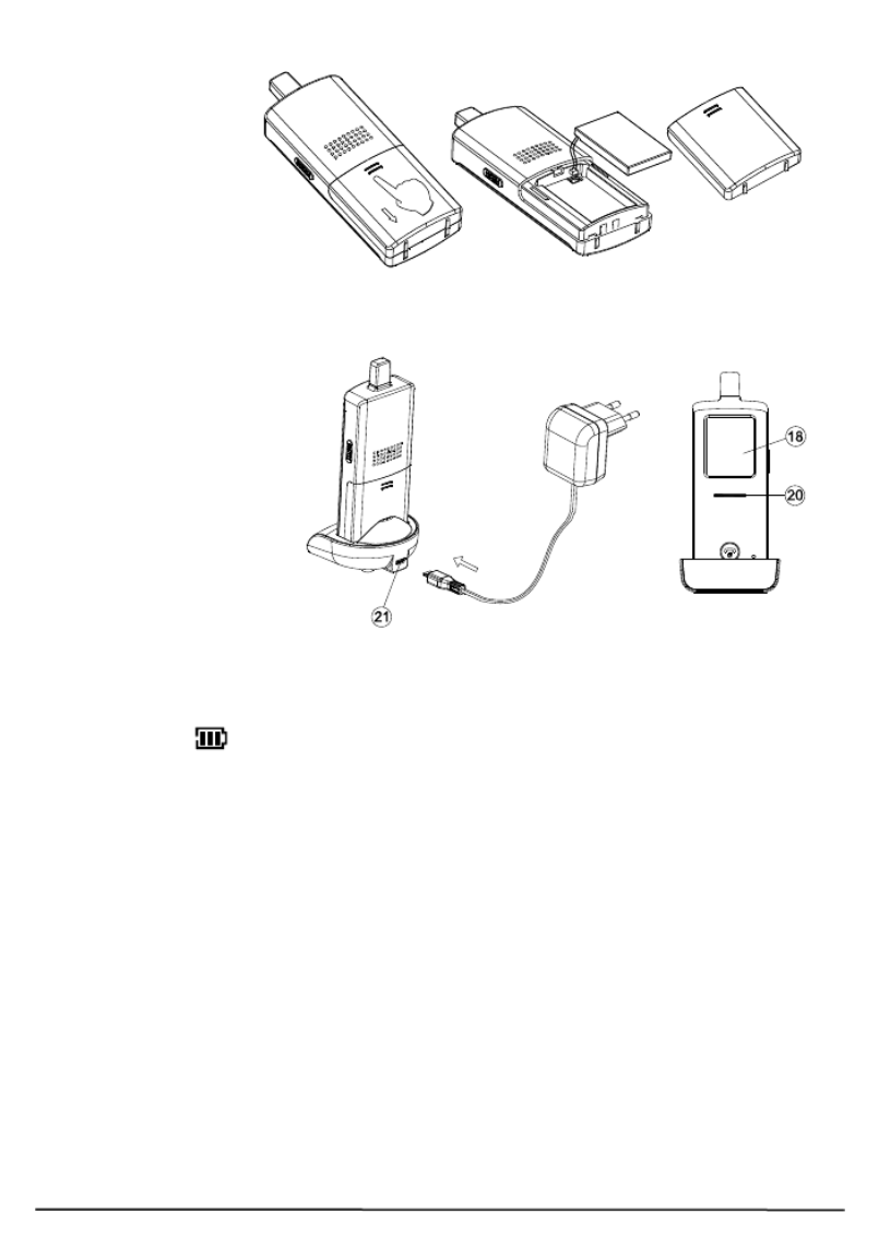
7.1.3 Handset
The supplied Li
polymer battery
pack is already
installed in the
handset. (To
replace the battery,
press down and
slide open the
battery door in the direction as shown, take out the battery pack and
disconnect it from the socket.
With the handset
remaining switched off,
place it onto the charger
stand.
Plug in the supplied AC
switching power supply
into an AC outlet and
connect its output plug
to the USB port (21)
located at the back of
the charger stand.
The power indicator (20)
should light up red during the charging process. Adjust the position of the
handset in the charger stand in case this indicator does not light up.
During charging, in case the screen (18) is turned on, the segments within
the battery icon will flash in turn.
The battery pack should be fully charged within 4 hours when used for the
first time. The power indicator (20) will now go off (if the handset is
switched off) or turn steady blue (if the handset is switched on).
Now the unit can be switched on and is ready for operation. Either taking
out the unit or keeping it placed in the charger stand will cause no
damage to the battery. In the latter case, when the battery is being
consumed and voltage falls to a certain level, the charger stand will
automatically charge up the battery.
CAUTION: BE SURE THE BATTERY IN THE HANDSET IS A
RECHARGEABLE TYPE BEFORE YOU PLACE IT IN THE CHARGER
STAND, OTHERWISE AN EXPLOSION MAY RESULT.

© MARMITEK
10
and select “BACK”. The original front gate unit does not need to be paired
again.
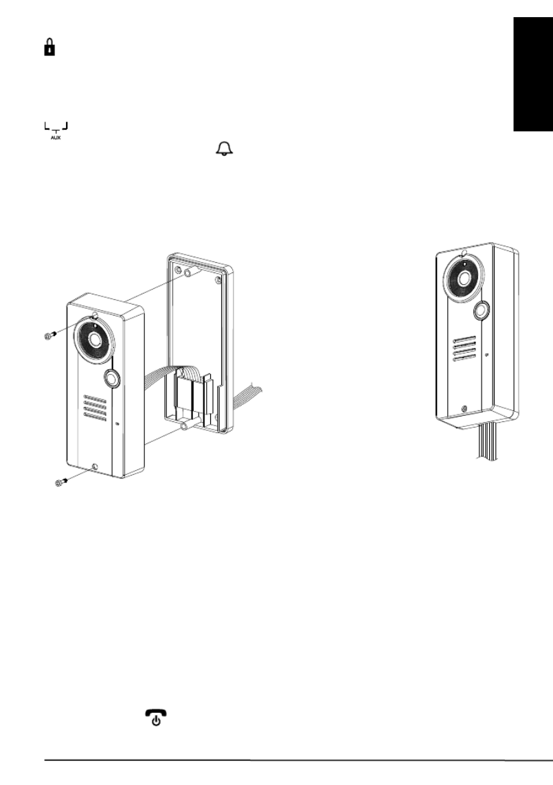
7.3 Mounting of door Unit
Select a location near your door
entrance where the surface is not too
rough. We recommend that you do
some polishing to get a plane surface or
otherwise the unit may not be able to
mount properly.
It should be noted that the mounting
bracket is not installed on metal
screening surfaces nor in the vicinity of
other electronic devices that may reduce
the operating range. Using the supplied
self tap screws, fix the mounting bracket
onto the wall.
Connect the terminals marked of
the 12V DC power supply at the back
of the door unit. In addition, there are
also terminals marked and
for connecting to an electric door latch
which can be remotely opened by the
handset. When the DC power supply
is connected, the call button (1) will
be illuminated. The electric door latch
opening feature will not operate when
using the backup alkaline batteries so as to keep long battery life.
CAUTION: When using the DC supply, in case the electric door latch
does not function, reverse the polarity it is connected to and try
again.
(The two most common types of electric door latch on the market are
either “always close” or “always open”.)
7.3.1 Always close
These two terminals normally provide a 12V supply. During
communication, once the door lock opening button (13) is pressed, this
voltage will drop to 0V temporarily for duration of time as specified by the
TRIGGER TIME function.
7.3.2 Always open
These two terminals normally provide 0V. During communication,
once the door lock opening button (13) is pressed, the terminals will
Drilled holes
Insert the plugs into the holes
(for concrete wall only)
Video DoorPhone 210
11
ENGLISH
provide a 12V supply temporarily for duration of time as specified by the
TRIGGER TIME function.
Under no circumstances should AC mains Voltage be directly connected
to the terminal blocks (8)!
7.3.3 Auxiliary terminal
These two terminals act like a switch and will be short circuited as
long as the doorbell button (1) is pressed, however, there is no voltage
supply from these terminals. They can be used to trigger a conventional
door chime or a courtesy light at the entrance.
Now insert the 3 pcs AAA (UM-4) alkaline batteries into the battery
compartment as this can serve as a battery back-up in case the 12V DC
supply fails.
Install the back of the door unit onto the mounting bracket using the
supplied tool.
The door unit is housed in a high impact ABS/PC cabinet, which can
achieve the professional grade ruggedness required in most outdoor
applications. Rubber gaskets seal around all of the joints keep out dust,
rain, snow and spray, assuring years of reliable operation even in harsh
environments. The unit meets to IP-54 standard and can operate
from -20˚C to 50˚C.
8 Operation
8.1 ON / OFF
Switch on the handset by a long press (over 3 seconds) of the Power
ON/OFF button (15). (Long press the same button again in case you
want to switch off the unit.)
To DC supply
and electric
door lock
The connecting wire can
come out from the
opening at
the bottom in case not
concealed in the wall

© MARMITEK
12
The power indicator (20) will light up blue. In case the Li battery has run
down, the power indicator will start flashing blue. At the same time, the
battery icon shown on screen (18) will become empty and flashing.
Place the unit into the charger stand to charge up the battery.
During standby mode, a short press of the Talk/answer
button / (16) will initiate communication with the
door unit and wake up the screen (18) showing the
view as captured by the lens (6) (In case a backgate
caller unit has been installed, the screen (18) will
prompt you to select “FRONT” or “BACK”. Use the
left/right key (9) (10) to select and menu key (11)
to confirm.).
Long touch the menu key (11) for over 2 sec to
show the menu on the screen (18):
Use the left/right key (9) (10) to select the
parameters to be set, then short touch the menu key
(11) to confirm. The selectable values now show
yellow while the parameter description resumes the
light blue colour.
9 Caller setting
9.1 Gate
This will select the door unit you prefer to change the
settings for. Use the left/right key (9) (10) to select
between FRONT or BACK gate, then short touch the
menu key (11) to confirm your setting.
9.2 Volume
This will set the speaker volume of the door unit. Use
the left/right key (9) (10) to select between the 5
levels with 1 being the lowest and 5 being the highest volume. Short
touch the menu key (11) to confirm your setting.
9.3 Brightness
This will set the brightness of the visitor’s image as shown on the screen
(18). Use the left/right key (9) (10) to select between the 5 levels with
1 being the lowest and 5 being the highest brightness. Short touch the
menu key (11) to confirm your setting.
© MARMITEK
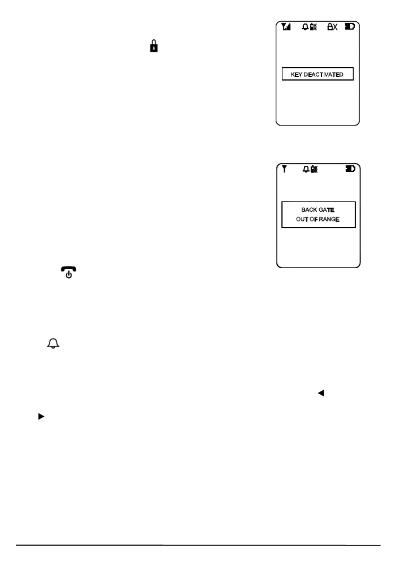
16
To avoid misuse by children, this door lock opening
function can be activated or deactivated. When
deactivated, touching the key (13) will have no effect
and the text “KEY DEACTIVATED” will show on the
screen (18) for 2-3 sec.
Whenever the handset is located at a spot which is
outside the communication range of the caller unit
(either front or back gate or both), an alarm will be
heard and the screen (18) will show the following:
Such alarm cannot be immediate and will alert you only
when you are out of range for over 2 minutes (when
12V DC supply is available or 20 minutes if a battery is
used). Once the handset falls back in range, the alarm
will stop automatically. A short press of the power/hang
up button (15) can cut off the alarm sound but the
“out of range” text will continue flashing on the screen (18) until the
handset falls within the range of the caller unit.
N.B. This out of range alert will also occur in case the batteries of the
caller unit run down and its DC power is cut off.
When the Light sensor (5) detects a low light intensity, once the call
button (1) is pressed, the white illumination LED (4) will light up
automatically to illuminate the face of the visitor. This is subjected to
“AUTO” being selected for the GATE LIGHT function menu.
A beep sound will be heard whenever a key is being touched to validate
your entry. To eliminate such a beep sound, long touch the left key (9)
until a second beep is heard. To resume the beep sound, long touch the
right (10) key until a beep sound is heard.

Video DoorPhone 210
21
DEUTSCH
1 Sicherheitshinweise
x Setzen Sie die Komponenten Ihres Systems nicht extrem hohen
Temperaturen oder starken Lichtquellen aus.
x Bei einer zweckwidrigen Verwendung, selbst angebrachten
Veränderungen oder selbst ausgeführten Reparaturen verfallen alle
Garantiebestimmungen. Marmitek übernimmt bei einer falschen
Verwendung des Produkts oder bei einer anderen Verwendung des
Produktes als für den vorgesehenen Zweck keinerlei Produkthaftung.
Marmitek übernimmt für Folgeschäden keine andere Haftung als die
gesetzliche Produkthaftung.
x Dieses Produkt ist kein Spielzeug. Außer Reichweite von Kindern
halten.
x Das Produkt niemals öffnen (ausgen.des Batteriefachs): Das Gerät
kann Teile enthalten, worauf lebensgefährliche Stromspannung steht.
Überlassen Sie Reparaturen oder Wartung nur Fachleuten.
x Halten Sie die Batterien außerhalb der Reichweite von Kindern.
Liefern Sie die Batterien als chemischen Kleinabfall ein. Verwenden
Sie niemals alte und neue oder unterschiedliche Typen von Batterien
durcheinander. Wenn Sie das System längere Zeit nicht benutzen,
entfernen Sie die Batterien. Achten Sie beim Einlegen der Batterien
auf die Polarität (+ / -): Ein falsches Einlegen kann zu
Explosionsgefahr führen.
x Schließen Sie den Netzadapter erst dann an das Stromnetz an,
nachdem Sie überprüft haben, ob die Netzspannung mit dem auf
dem Typenschild angegeben Wert übereinstimmt. Schließen Sie
niemals einen Netzadapter oder ein Netzkabel an, wenn diese
beschädigt sind. In diesem Fall nehmen Sie Kontakt mit Ihrem
Lieferanten auf.
Produktspecifikationer
| Varumärke: | Marmitek |
| Kategori: | Intercomsystem |
| Modell: | DoorPhone 210 |
Behöver du hjälp?
Om du behöver hjälp med Marmitek DoorPhone 210 ställ en fråga nedan och andra användare kommer att svara dig
Intercomsystem Marmitek Manualer

14 September 2024
9 September 2024
23 Augusti 2024
15 Augusti 2024
Intercomsystem Manualer
- Intercomsystem Philips
- Intercomsystem Panasonic
- Intercomsystem Abus
- Intercomsystem Alecto
- Intercomsystem Acti
- Intercomsystem Hikvision
- Intercomsystem Silvercrest
- Intercomsystem Elro
- Intercomsystem EMOS
- Intercomsystem DataVideo
- Intercomsystem Axis
- Intercomsystem Byron
- Intercomsystem Chamberlain
- Intercomsystem Midland
- Intercomsystem Smartwares
- Intercomsystem Steren
- Intercomsystem Viking
- Intercomsystem Somfy
- Intercomsystem Dahua Technology
- Intercomsystem Rollei
- Intercomsystem DIO
- Intercomsystem Siedle
- Intercomsystem Valcom
- Intercomsystem Chacon
- Intercomsystem Bticino
- Intercomsystem Sygonix
- Intercomsystem Planet
- Intercomsystem Konig
- Intercomsystem Becken
- Intercomsystem Foscam
- Intercomsystem Busch-Jaeger
- Intercomsystem Swann
- Intercomsystem Extel
- Intercomsystem M-e
- Intercomsystem DoorBird
- Intercomsystem Gira
- Intercomsystem Fibaro
- Intercomsystem Russound
- Intercomsystem Comelit
- Intercomsystem Fanvil
- Intercomsystem Aiphone
- Intercomsystem Avidsen
- Intercomsystem Crestron
- Intercomsystem ORNO
- Intercomsystem Monacor
- Intercomsystem Sonifex
- Intercomsystem RTS
- Intercomsystem Nortek
- Intercomsystem Vimar
- Intercomsystem ZKTeco
- Intercomsystem Akuvox
- Intercomsystem Schwaiger
- Intercomsystem Bitron
- Intercomsystem Hollyland
- Intercomsystem Hanwha
- Intercomsystem Leviton
- Intercomsystem EtiamPro
- Intercomsystem Pentatech
- Intercomsystem Ritto
- Intercomsystem Arenti
- Intercomsystem Syscom
- Intercomsystem Elcom
- Intercomsystem Pentatron
- Intercomsystem CyberData Systems
- Intercomsystem COMMAX
- Intercomsystem Bintec-elmeg
- Intercomsystem Eartec
- Intercomsystem Gewiss
- Intercomsystem TCS
- Intercomsystem Seco-Larm
- Intercomsystem NuTone
- Intercomsystem GEV
- Intercomsystem Tador
- Intercomsystem WHD
- Intercomsystem Mobotix
- Intercomsystem FlyingVoice
- Intercomsystem Vibell
- Intercomsystem Toucan
- Intercomsystem 2N Telecommunications
- Intercomsystem Louroe Electronics
Nyaste Intercomsystem Manualer
28 Mars 2025
27 Mars 2025
27 Mars 2025
27 Mars 2025
27 Mars 2025
11 Mars 2025
10 Mars 2025
9 Mars 2025
2 Mars 2025
20 Februari 2025